2005 Front drive system service manual E.indd
2005 Front drive system service manual E.indd
2005 Front drive system service manual E.indd

Create successful ePaper yourself
Turn your PDF publications into a flip-book with our unique Google optimized e-Paper software.
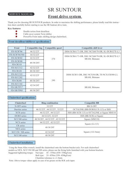
SERVICE MANUAL<br />
SR SUNTOUR<br />
<strong>Front</strong> <strong>drive</strong> <strong>system</strong><br />
Thank you for choosing SR SUNTOUR products. In order to maximize the shifting performance, please kindly read this instruction<br />
sheet carefully before starting to use the SR Suntour <strong>drive</strong> train.<br />
Key features<br />
Double action front derailleur.<br />
Cable saver <strong>system</strong> Twist shifter.<br />
PowerFlo <strong>Front</strong> index shifting design chainwheel.<br />
<strong>Front</strong> derailleur/shiftlever specifi cations<br />
<strong>Front</strong> Compatible ring Compatible speed Compatible shift lever<br />
FD-XCR706 46/32/22T<br />
DSM-XCR61/71-DR, DSC-NCX60/70-DR, SL-DURO27E-L3<br />
FD-XCR704/504<br />
FD-XCR502<br />
44/32/22T<br />
42/32/22T<br />
27S<br />
DSM-XCR61/71-DR, DSC-NCX60/70-DR, SL-DURO27E-L3<br />
SRAM, Shimano<br />
FD-XCR508<br />
FD-CR318<br />
48/38/28T<br />
FD-XCC312 42/32/22T<br />
FD-CR328 48/38/28T<br />
FD-XCC322<br />
FD-XCC202<br />
42/32/22T<br />
FD-CR208 48/38/28T<br />
FD-XCC102<br />
FD-XR/TP17<br />
42/34/24T<br />
FD-XR/TP05 48/38/28T<br />
Chainwheel specifi cations<br />
24S<br />
DSM-XCR51-DR, DSC-NCX50-DR, TS-NCX/CR500-L3,<br />
SRAM, Shimano<br />
SRAM, Shimano<br />
Chainwheel Ring combination Compatible BB<br />
X-OFF series 32/22T BB-X-OFF<br />
Durolux series 46/32/22T , 44/32/22T , 32/22T OCTALINK (BB-DUROLUX-113) or ISIS<br />
XCR series 46/32/22T , 44/32/22T ISIS (BB-XCR-113) or OCTALINK or Square MM110<br />
DURO series 44/32/22T, 32/22T ISIS (BB-XCR) or Square<br />
XCC300 series 48/38/28T , 44/32/22T , 42/32/22T Square (MM110)<br />
NCX series<br />
CR series<br />
NEX series<br />
44/32/22T , 42/32/22T<br />
48/38/28T<br />
Square (LL113)<br />
XCC150 / XR series 42/34/24T<br />
Square (122.5mm)<br />
XCC100 series 48/38/28T<br />
Chainwheel installation<br />
Using the 8mm Allen wrench, install the chainwheel onto the bottom bracket axle. For such chainwheel<br />
models as NEX, XCC150/100 and XR series, please use the fi xing bolts furnished with your bottom brackets.<br />
Suggested tightening torque: Nut type: 45 - 55Nm (450- 550kgf/cm)<br />
Bolt type: 35- 45Nm (350- 450kgf/cm)<br />
Chainline tolerance is ±1.5mm.<br />
Note: Above torque values apply in case of no grease on the B.B. axle taper.
<strong>Front</strong> derailleur installation<br />
Level<br />
<strong>Front</strong> derailleur position<br />
With the outer cage directly over and parallel to the outer chainring,<br />
be sure to adjust the clearance between the level section of<br />
the outer cage and outer chainring to be 1-3mm as shown [A].<br />
For easier installation, fi rst position the front derailleur on the<br />
smallest chainring temporarily, so that the clearance between the<br />
outer cage and outer chainring is about 1mm as shown [B].<br />
NOTE (all <strong>Front</strong> derailleurs except for FD-XR/TP series)<br />
A B<br />
Dual diameter compatible clamp design allows you to choose<br />
either 31.8 or 34.9mm seat tube. Before you install the front derail-<br />
Outer ring<br />
Outer cage<br />
leur, check the seat tube diameter to have correct clamp. If it is 34.9mm, then remove the plastic adaptor from the clamp band.<br />
Control installation<br />
Insert the control to the handle bar as described below.<br />
Note<br />
*DSC type controls<br />
When using DSC type controls, please be sure to use the grip length that is more than 62mm for<br />
proper grip.<br />
*TS type control<br />
Before installing grips, be sure to put the 0.5mm slide washers between the controls and grips.<br />
After installing grips, adjust the position of the controls, making sure not to push them too hard<br />
against grips. Otherwise it may affect the shifting function and make the operation heavier.<br />
Handlebar dimension<br />
1.9 Nm<br />
3mm Allen wrench<br />
Suggested tightening torque<br />
5Nm<br />
5mm Allen wrench<br />
DSM & DSC types SL-DURO type<br />
When using the SR SUNTOUR Control, it is necessary to maintain<br />
straight section „L“ at the handlebar ends as shown below. Please<br />
select handlebars according to the dimensions shown here.<br />
SL-DURO type<br />
Straight section on „L“<br />
13mm + Brake bracket size (A) + Grip length<br />
DSM type Brake bracket size (A) + 54mm + Grip length<br />
DSC type Brake bracket size (A) + 88mm + B (should be<br />
more than 62mm)<br />
TS type 72mm + Grip length<br />
13mm A<br />
SL-DURO TYPE<br />
Grip length<br />
L<br />
A<br />
A<br />
54mm<br />
Do not push too hard toward<br />
the movable grip<br />
DSC-TYPE<br />
L<br />
Tightening torque<br />
7 - 9 Nm<br />
Grip length<br />
DSM-TYPE<br />
5mm Allen<br />
wrench<br />
88mm Grip length 62+<br />
L
Chain length<br />
In order to get maximum shifting performance, please follow the points below to determine the proper chain length.<br />
Chainwheel: 42T, 44T, 46T or 48T outer ring Chainwheel: 42T, 44T, 46T or 48T outer ring<br />
Rear largest sprocket: 30T or 32T<br />
Add 4 links after putting the chain on the front<br />
and rear largest sprockets.<br />
Inner cable connection<br />
1. Set the control to the stopper position as shown in the indicator [1].<br />
2. This Dual-pull <strong>system</strong> allows to have down-pull cable routing or top-<br />
pull cable routing. So choose the proper cable routing as shown here.<br />
3. After taking up the initial slack of cable, connect the inner cable to the<br />
front derailleur.<br />
4. Tighten the inner cable fi xing bolt with a 5mm Allen wrench.<br />
Suggested tightening torque: 5-7 Nm.<br />
Inner cable fi xing bolt<br />
Down-pull cable connection Top-pull cable connection<br />
Cassette<br />
Rear largest sprocket: 34T<br />
Add 2 links after putting the chain on the front<br />
and rear largest sprockets.<br />
Add 4 links (with chain tightened) Add 2 links (with chain tightened)<br />
Index adjustment<br />
1. Shifting range<br />
Low adjustment<br />
Turn the Low adjustment screw<br />
so that the clearance between the<br />
Inner plate and the chain is at 0.5-<br />
1.0mm.<br />
B A<br />
Center adjustment<br />
Set the chain onto the largest rear<br />
sprocket and center chainring.<br />
Adjust the position of the front<br />
derailleur, using the outer casing<br />
adjustment barrel on the control, so<br />
that the clerance between the Inner<br />
plate and the chain to be at around<br />
0.5-1.0mm.<br />
Top adjustment<br />
Turn the Top adjustment screw<br />
so that the clearance between the<br />
Outer plate and the chain to be at<br />
0.5-1.0mm. B A<br />
Inner<br />
plate<br />
Chain<br />
Inner plate<br />
Chain<br />
A B<br />
B A<br />
Stopper<br />
position<br />
Low „L“<br />
adjustment<br />
Around<br />
0,5-1,0mm<br />
clearance<br />
Around<br />
0,5-1,0mm<br />
clearance<br />
Top „H“<br />
adjustment<br />
Outer plate<br />
Around<br />
0,5-1,0mm<br />
clearance<br />
Chain<br />
3<br />
<strong>Front</strong> chainwheel<br />
SL-DURO type<br />
<strong>Front</strong> derailleur control at stopper positon<br />
1<br />
DSM/DSC types<br />
1<br />
3<br />
Outer casing adjustment<br />
barrel<br />
DSM/DSC types SL-DURO type
2. Troubleshooting of the adjustment<br />
10. After completing the above steps, move the shift lever to see the shifting performance.<br />
If shifting from the smallest chainring to the center ring is diffi cult. Turn the outer casing adjustment barrel on the control counterclockwise<br />
(about 1/4 turns).<br />
If shifting from the center chainring to the outer ring is diffi cult. Turn the top adjustment screw on the front derailleur counterclockwise<br />
(about 1/4 turns).<br />
If the chain falls to the crank side. Turn the top adjustment screw on the front derailleur clockwise<br />
(about 1/4 turns).<br />
If shifting from the outer chainring to the center ring is diffi cult. Turn the outer casing adjustment barrel on the control clockwise<br />
(about 1/4 turns).<br />
If shifting from the center chainring to the smallest ring is diffi cult. Turn the low adjustment screw on the front derailleur counterclockwise<br />
(about 1/4 turns).<br />
If the chain falls to the bottom bracket side. Turn the low adjustment screw on the front derailleur clockwise<br />
(about 1/4 turns).<br />
When the chain is on the center chainring, if there is interference<br />
between the chain and front derailleur outer plate when shifted to<br />
the smallest sprocket and interference between the chain and front<br />
derailleur inner plate when shifted to the largest sprocket.<br />
Control operation<br />
When operating the controls, always be sure to turn the crank arm at the same time.<br />
Rotate the movable grip to the (A) direction to shift from smaller chainring to a larger ring and to the (B) direction to shift<br />
from a larger chainring to a smaller ring.<br />
������������<br />
A<br />
Replacing the inner cable<br />
B<br />
A B<br />
DSM/DSC types<br />
�<br />
A<br />
TS type<br />
1. Return the control to stopper position.<br />
2. Open the indicator window by a fi nger or a screw <strong>drive</strong>r (-). (For TS type: Loosen the cap screw counter-clockwise with a<br />
2.5mm allen wrench.)<br />
3. Push out the old inner cable, and install the new inner cable. At this time, check to see if the control is at the stopper position.<br />
4. Close the indicator window. (For TS type: Tighten the cap screw clockwise with a 2.5mm allen wrench.<br />
Suggested tightening torque is 0.05Nm. Then close the cable replacement port.)<br />
DSM/DSC types<br />
3<br />
1st step: Return the lever to the<br />
stopper position<br />
1<br />
CABLE NIPPLE NIPPLE STOPPER<br />
5<br />
2<br />
SLOT<br />
4th step: Push<br />
down the nipple<br />
stopper and take<br />
out the old cable.<br />
Insert the new<br />
cable.<br />
2nd step: Open the<br />
indicator window.<br />
3<br />
The level section of the outer plate should be directly above and<br />
parallel to the largest chainring.<br />
3rd step: Take out the<br />
cable nipple.<br />
6 7<br />
4
Replacing the inner cable<br />
1. Return the control to stopper position.<br />
2. Open the indicator window by a fi nger or a screw <strong>drive</strong>r (-).<br />
(For TS type: Loosen the cap screw counter-clockwise with a<br />
2.5mm allen wrench.)<br />
3. Push out the old inner cable, and install the new inner cable.<br />
At this time, check to see if the control is at the stopper position.<br />
4. Close the indicator window. (For TS type: Tighten the cap<br />
screw clockwise with a 2.5mm allen wrench.<br />
Suggested tightening torque is 0.05Nm. Then close the cable<br />
replacement port.)<br />
Stopper position<br />
2.5 Allen key<br />
LIMITED WARRANTY<br />
SR SUNTOUR warrants the <strong>drive</strong> train to be free from defects in materials and workmanship under normal use for a period of<br />
two years from the date of purchase. In no event shall this limited warranty apply to any defect of the <strong>drive</strong> train caused by: improper<br />
installation, disassembly, reassembly, intentional breakage or damage, alterations or modifi cations to the <strong>drive</strong> train by the<br />
user or other party or any unreasonable use or abuse of the product or any use for which this product was not intended.<br />
The obligation of this limited warranty shall be limited to repairing or replacing the <strong>drive</strong> train or any part for which there is a<br />
defect in materials or workmanship during the two years following the date of purchase. To validate this limited warranty the<br />
purchaser must submit this warranty card to SR SUNTOUR within 30 days after purchase of the <strong>drive</strong> train. Any alteration of, or<br />
tampering with the warranty card automatically terminates this limited warranty.<br />
SR SUNTOUR makes no express or implied warranties of fi tness or merchatability of any kind, except as set forth above. SR<br />
SUNTOUR’s liability hereunder is expressly limited to repair or replacement of the product. Under no circumstances will SR<br />
SUNTOUR be liable for incidental or consequential damages. Some jurisdictions do not allow the exclusion or limitation of liability<br />
of incidental or consequential damages, so the above exclusion may not apply to you. This warranty gives you specifi c rights<br />
and you may have other rights which vary from jurisdiction to jurisdiction.<br />
Drive Train Warranty Card:<br />
Date of purchase: Model name<br />
Term of limited warranty: Two years from the date of purchase<br />
Dealer Name: Phone#:<br />
Address:<br />
Purchaser Name: Phone#:<br />
Address:<br />
CABLE NIPPLE<br />
This warranty is void without proof of purchase.<br />
SR SUNTOUR INC.<br />
No.7 Hsing Yeh Road, Fu Hsing Industrial Zone.Changhua.50606. Taiwan, R.O.C.<br />
Tel:00886-4-7695115 / Fax: 00886-4-769 4028 / E-mail: orders@srsuntour.com.tw<br />
SR SUNTOUR USA<br />
P.O. Box 61988 Vancouver WA 98666<br />
Tel: 1- 360 737 6450 / Fax: 1 360 737 6452 /<br />
E-mail: <strong>service</strong>@usulcorp.com<br />
5<br />
SLOT<br />
NIPPLE STOPPER<br />
5th step: Push down the nipple<br />
stopper, in order to release the cable<br />
nipple - take out the old cable.<br />
1<br />
2<br />
3<br />
1<br />
1st step: Return the lever to the<br />
stopper position<br />
2nd step: Open the indicator window,<br />
using a fl at screw<strong>drive</strong>r.<br />
6 7<br />
3<br />
3rd step: Open the indicator window,<br />
SR SUNTOUR EUROPE S.A.<br />
Chaussee de Tervueren,43,1410 Waterloo. Belgium<br />
Tel: 0032-2-3544676 / Fax: 0032-2-354 7835 /<br />
E-mail: <strong>service</strong>@srsuntoureurope.com<br />
SR SUNTOUR INC.<br />
Specifi cations are subject to change without notice.<br />
Printed in TAIWAN.<br />
4<br />
������������<br />
4th step: Take out the cable nipple.