2005 Front drive system service manual E.indd
2005 Front drive system service manual E.indd
2005 Front drive system service manual E.indd

Create successful ePaper yourself
Turn your PDF publications into a flip-book with our unique Google optimized e-Paper software.
2. Troubleshooting of the adjustment<br />
10. After completing the above steps, move the shift lever to see the shifting performance.<br />
If shifting from the smallest chainring to the center ring is diffi cult. Turn the outer casing adjustment barrel on the control counterclockwise<br />
(about 1/4 turns).<br />
If shifting from the center chainring to the outer ring is diffi cult. Turn the top adjustment screw on the front derailleur counterclockwise<br />
(about 1/4 turns).<br />
If the chain falls to the crank side. Turn the top adjustment screw on the front derailleur clockwise<br />
(about 1/4 turns).<br />
If shifting from the outer chainring to the center ring is diffi cult. Turn the outer casing adjustment barrel on the control clockwise<br />
(about 1/4 turns).<br />
If shifting from the center chainring to the smallest ring is diffi cult. Turn the low adjustment screw on the front derailleur counterclockwise<br />
(about 1/4 turns).<br />
If the chain falls to the bottom bracket side. Turn the low adjustment screw on the front derailleur clockwise<br />
(about 1/4 turns).<br />
When the chain is on the center chainring, if there is interference<br />
between the chain and front derailleur outer plate when shifted to<br />
the smallest sprocket and interference between the chain and front<br />
derailleur inner plate when shifted to the largest sprocket.<br />
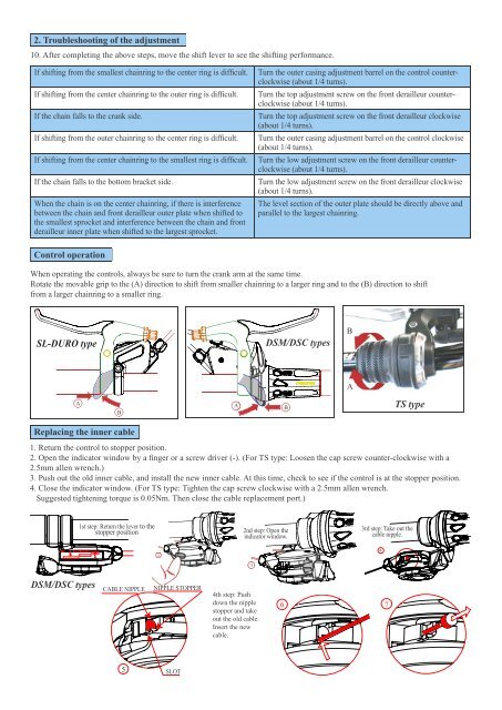
Control operation<br />
When operating the controls, always be sure to turn the crank arm at the same time.<br />
Rotate the movable grip to the (A) direction to shift from smaller chainring to a larger ring and to the (B) direction to shift<br />
from a larger chainring to a smaller ring.<br />
������������<br />
A<br />
Replacing the inner cable<br />
B<br />
A B<br />
DSM/DSC types<br />
�<br />
A<br />
TS type<br />
1. Return the control to stopper position.<br />
2. Open the indicator window by a fi nger or a screw <strong>drive</strong>r (-). (For TS type: Loosen the cap screw counter-clockwise with a<br />
2.5mm allen wrench.)<br />
3. Push out the old inner cable, and install the new inner cable. At this time, check to see if the control is at the stopper position.<br />
4. Close the indicator window. (For TS type: Tighten the cap screw clockwise with a 2.5mm allen wrench.<br />
Suggested tightening torque is 0.05Nm. Then close the cable replacement port.)<br />
DSM/DSC types<br />
3<br />
1st step: Return the lever to the<br />
stopper position<br />
1<br />
CABLE NIPPLE NIPPLE STOPPER<br />
5<br />
2<br />
SLOT<br />
4th step: Push<br />
down the nipple<br />
stopper and take<br />
out the old cable.<br />
Insert the new<br />
cable.<br />
2nd step: Open the<br />
indicator window.<br />
3<br />
The level section of the outer plate should be directly above and<br />
parallel to the largest chainring.<br />
3rd step: Take out the<br />
cable nipple.<br />
6 7<br />
4