TUB 2765 SHS Welded Joints - Tata Steel
TUB 2765 SHS Welded Joints - Tata Steel
TUB 2765 SHS Welded Joints - Tata Steel

You also want an ePaper? Increase the reach of your titles
YUMPU automatically turns print PDFs into web optimized ePapers that Google loves.
09 Design of <strong>SHS</strong> welded joints<br />
e > 0<br />
e < 0<br />
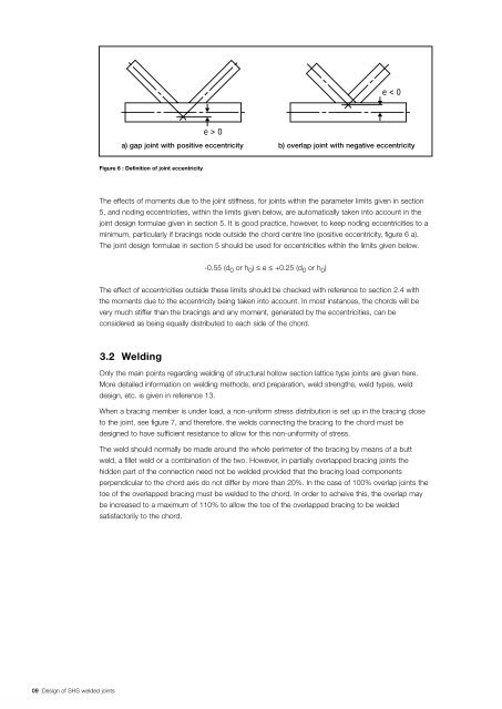
a) gap joint with positive eccentricity b) overlap joint with negative eccentricity<br />
Figure 6 : Definition of joint eccentricity<br />
The effects of moments due to the joint stiffness, for joints within the parameter limits given in section<br />
5, and noding eccentricities, within the limits given below, are automatically taken into account in the<br />
joint design formulae given in section 5. It is good practice, however, to keep noding eccentricities to a<br />
minimum, particularly if bracings node outside the chord centre line (positive eccentricity, figure 6 a).<br />
The joint design formulae in section 5 should be used for eccentricities within the limits given below.<br />
-0.55 (d 0 or h 0 ) ≤ e ≤ +0.25 (d 0 or h 0 )<br />
The effect of eccentricities outside these limits should be checked with reference to section 2.4 with<br />
the moments due to the eccentricity being taken into account. In most instances, the chords will be<br />
very much stiffer than the bracings and any moment, generated by the eccentricities, can be<br />
considered as being equally distributed to each side of the chord.<br />
3.2 Welding<br />
Only the main points regarding welding of structural hollow section lattice type joints are given here.<br />
More detailed information on welding methods, end preparation, weld strengths, weld types, weld<br />
design, etc. is given in reference 13.<br />
When a bracing member is under load, a non-uniform stress distribution is set up in the bracing close<br />
to the joint, see figure 7, and therefore, the welds connecting the bracing to the chord must be<br />
designed to have sufficient resistance to allow for this non-uniformity of stress.<br />
The weld should normally be made around the whole perimeter of the bracing by means of a butt<br />
weld, a fillet weld or a combination of the two. However, in partially overlapped bracing joints the<br />
hidden part of the connection need not be welded provided that the bracing load components<br />
perpendicular to the chord axis do not differ by more than 20%. In the case of 100% overlap joints the<br />
toe of the overlapped bracing must be welded to the chord. In order to acheive this, the overlap may<br />
be increased to a maximum of 110% to allow the toe of the overlapped bracing to be welded<br />
satisfactorily to the chord.