TUB 2765 SHS Welded Joints - Tata Steel
TUB 2765 SHS Welded Joints - Tata Steel
TUB 2765 SHS Welded Joints - Tata Steel

Create successful ePaper yourself
Turn your PDF publications into a flip-book with our unique Google optimized e-Paper software.
40<br />
41 Design of <strong>SHS</strong> welded joints<br />
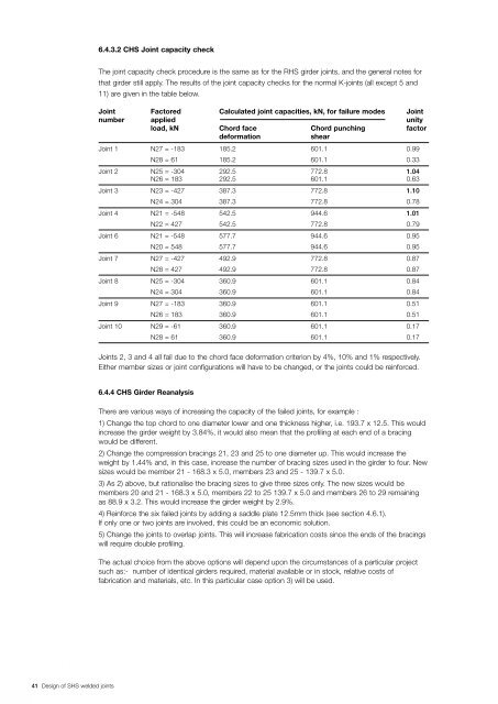
6.4.3.2 CHS Joint capacity check<br />
The joint capacity check procedure is the same as for the RHS girder joints, and the general notes for<br />
that girder still apply. The results of the joint capacity checks for the normal K-joints (all except 5 and<br />
11) are given in the table below.<br />
Joint Factored Calculated joint capacities, kN, for failure modes Joint<br />
number applied unity<br />
load, kN Chord face Chord punching factor<br />
deformation shear<br />
Joint 1 N27 = -183 185.2 601.1 0.99<br />
N28 = 61 185.2 601.1 0.33<br />
Joint 2 N25 = -304 292.5 772.8 1.04<br />
N26 = 183 292.5 601.1 0.63<br />
Joint 3 N23 = -427 387.3 772.8 1.10<br />
N24 = 304 387.3 772.8 0.78<br />
Joint 4 N21 = -548 542.5 944.6 1.01<br />
N22 = 427 542.5 772.8 0.79<br />
Joint 6 N21 = -548 577.7 944.6 0.95<br />
N20 = 548 577.7 944.6 0.95<br />
Joint 7 N27 = -427 492.9 772.8 0.87<br />
N28 = 427 492.9 772.8 0.87<br />
Joint 8 N25 = -304 360.9 601.1 0.84<br />
N24 = 304 360.9 601.1 0.84<br />
Joint 9 N27 = -183 360.9 601.1 0.51<br />
N26 = 183 360.9 601.1 0.51<br />
Joint 10 N29 = -61 360.9 601.1 0.17<br />
N28 = 61 360.9 601.1 0.17<br />
<strong>Joints</strong> 2, 3 and 4 all fail due to the chord face deformation criterion by 4%, 10% and 1% respectively.<br />
Either member sizes or joint configurations will have to be changed, or the joints could be reinforced.<br />
6.4.4 CHS Girder Reanalysis<br />
There are various ways of increasing the capacity of the failed joints, for example :<br />
1) Change the top chord to one diameter lower and one thickness higher, i.e. 193.7 x 12.5. This would<br />
increase the girder weight by 3.84%, it would also mean that the profiling at each end of a bracing<br />
would be different.<br />
2) Change the compression bracings 21, 23 and 25 to one diameter up. This would increase the<br />
weight by 1.44% and, in this case, increase the number of bracing sizes used in the girder to four. New<br />
sizes would be member 21 - 168.3 x 5.0, members 23 and 25 - 139.7 x 5.0.<br />
3) As 2) above, but rationalise the bracing sizes to give three sizes only. The new sizes would be<br />
members 20 and 21 - 168.3 x 5.0, members 22 to 25 139.7 x 5.0 and members 26 to 29 remaining<br />
as 88.9 x 3.2. This would increase the girder weight by 2.9%.<br />
4) Reinforce the six failed joints by adding a saddle plate 12.5mm thick (see section 4.6.1).<br />
If only one or two joints are involved, this could be an economic solution.<br />
5) Change the joints to overlap joints. This will increase fabrication costs since the ends of the bracings<br />
will require double profiling.<br />
The actual choice from the above options will depend upon the circumstances of a particular project<br />
such as:- number of identical girders required, material available or in stock, relative costs of<br />
fabrication and materials, etc. In this particular case option 3) will be used.