Describing an AUTOSAR System using UML/SysML - Automotive ...
Describing an AUTOSAR System using UML/SysML - Automotive ...
Describing an AUTOSAR System using UML/SysML - Automotive ...

Create successful ePaper yourself
Turn your PDF publications into a flip-book with our unique Google optimized e-Paper software.
White Paper<br />
Creating <strong>AUTOSAR</strong> <strong>System</strong>s Models Using the<br />
Combined Power of <strong>UML</strong> <strong>an</strong>d <strong>SysML</strong><br />
Richard F. Boldt<br />
This document contains proprietary information that belongs to Telelogic AB. Using <strong>an</strong>y of the<br />
information contained herein or copying or imaging all or part of this document by <strong>an</strong>y me<strong>an</strong>s is<br />
strictly forbidden without express written consent of Telelogic AB.<br />
Telelogic®, Telelogic Tau®, Telelogic DOORS®, Rhapsody®, Statemate® <strong>an</strong>d <strong>System</strong><br />
Architect® are registered trademarks. Telelogic Ch<strong>an</strong>ge <strong>an</strong>d Telelogic Synergy are<br />
trademarks of Telelogic AB – www.telelogic.com<br />
World Headquarters: Telelogic AB (publ.), PO Box 4128, SE-203 12 Malmö, Sweden, Phone: +46 40 650 00 00, Fax: +46 40 650 65 55<br />
Americ<strong>an</strong> Headquarters: Telelogic North America Inc., 9401 Jeronimo Road, Irvine, CA 92618, USA, Phone: +1 949 830 8022, Fax: +1 949 830 8023<br />
Web: www.telelogic.com, E-mail: info@telelogic.com
Creating <strong>AUTOSAR</strong> <strong>System</strong>s Models Using the Combined Power of <strong>UML</strong> <strong>an</strong>d <strong>SysML</strong><br />
Table of Contents<br />
Overview......................................................................................................................................... 3<br />
The <strong>AUTOSAR</strong> Process ................................................................................................................ 4<br />
<strong>Describing</strong> <strong>an</strong> <strong>AUTOSAR</strong> <strong>System</strong> <strong>using</strong> <strong>UML</strong>/<strong>SysML</strong>................................................................ 7<br />
Capturing the Functional <strong>System</strong> ................................................................................................ 8<br />
Internal Behavior Diagram............................................................................................................ 9<br />
<strong>System</strong>s Diagram ........................................................................................................................ 11<br />
Extending <strong>AUTOSAR</strong> with <strong>UML</strong> <strong>an</strong>d <strong>SysML</strong> ............................................................................. 12<br />
Conclusion ................................................................................................................................... 13<br />
Bibliography .......................................................................................................................... 13<br />
About Telelogic............................................................................................................................ 14<br />
World Headquarters: Telelogic AB (publ.), PO Box 4128, SE-203 12 Malmö, Sweden, Phone: +46 40 650 00 00, Fax: +46 40 650 65 55<br />
Americ<strong>an</strong> Headquarters: Telelogic North America Inc., 9401 Jeronimo Road, Irvine, CA 92618, USA, Phone: +1 949 830 8022, Fax: +1 949 830 8023<br />
Web: www.telelogic.com, E-mail: info@telelogic.com<br />
2 of 14
Overview<br />
Creating <strong>AUTOSAR</strong> <strong>System</strong>s Models Using the Combined Power of <strong>UML</strong> <strong>an</strong>d <strong>SysML</strong><br />
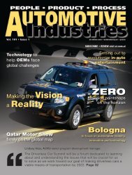
Developing today’s automobiles requires a seemingly ever-increasing number of<br />
software <strong>an</strong>d electronics applications for each automotive platform. Owing to the<br />
increased cost of the electronics <strong>an</strong>d the ability of the electronic features to differentiate<br />
one vehicle from <strong>an</strong>other, the automotive industry is scrutinizing how the electronics are<br />
developed <strong>an</strong>d deployed within <strong>an</strong> automobile. In response to this challenge, the<br />
<strong>AUTOSAR</strong> initiative was created. The <strong>AUTOSAR</strong> initiative has brought together leading<br />
automotive m<strong>an</strong>ufactures <strong>an</strong>d suppliers in a collaborative effort to define st<strong>an</strong>dards that<br />
will allow the reuse of hardware, software <strong>an</strong>d architecture from one vehicle to <strong>an</strong>other,<br />
while allowing the individual comp<strong>an</strong>ies to maintain their distinctive intellectual property.<br />
The goals of the <strong>AUTOSAR</strong> initiative are to create st<strong>an</strong>dard core solutions that enable<br />
the reuse <strong>an</strong>d scalability of functional modules between platform vari<strong>an</strong>ts. This includes<br />
different vehicles, together with whole product lifecycle support, plus software updates<br />
<strong>an</strong>d upgrades over the vehicle lifetime while also enabling <strong>an</strong> increased use of<br />
commercial off the shelf hardware (COTS). The <strong>AUTOSAR</strong> initiative covers all vehicle<br />
domains <strong>an</strong>d electronic applications; consequently, the st<strong>an</strong>dard must address critical<br />
industry dem<strong>an</strong>ds, such as reducing costs, allowing for the tr<strong>an</strong>sferability of functions<br />
throughout the network, integrations from multiple suppliers <strong>an</strong>d safety considerations.<br />
To address these needs, the <strong>AUTOSAR</strong> initiative has developed a layered software<br />
development approach that allows comp<strong>an</strong>ies to cooperate on st<strong>an</strong>dards <strong>an</strong>d compete<br />
on implementations. In order to implement <strong>an</strong> <strong>AUTOSAR</strong> process, however, it is critical<br />
to define the <strong>AUTOSAR</strong> system. Although this c<strong>an</strong> be done in several ways, a powerful<br />
<strong>an</strong>d extensible way is to use a Unified Modeling L<strong>an</strong>guage (<strong>UML</strong>) / Object M<strong>an</strong>agement<br />
Group (OMG) <strong>System</strong>s Modeling L<strong>an</strong>guage (<strong>SysML</strong>) profile tailored to meeting the<br />
<strong>AUTOSAR</strong> st<strong>an</strong>dards.<br />
This paper provides <strong>an</strong> overview of the fundamental concepts of <strong>AUTOSAR</strong> such as the<br />
<strong>AUTOSAR</strong> <strong>System</strong>, <strong>AUTOSAR</strong> Software Components, the <strong>AUTOSAR</strong> Virtual Functional<br />
Bus (VFB) <strong>an</strong>d the <strong>AUTOSAR</strong> Run Time Environments (RTE). An <strong>AUTOSAR</strong> <strong>System</strong><br />
consists of a set of interacting <strong>AUTOSAR</strong> Software Components communicating via the<br />
<strong>AUTOSAR</strong> VFB. This layered approach allows the <strong>AUTOSAR</strong> SW-Cs to be mapped to a<br />
specific Electronic Control Units (ECU) in a way such that these elements c<strong>an</strong> be<br />
distributed over <strong>an</strong> ECU network, while remaining correctly integrated to enable the<br />
reuse of software assets from one platform to <strong>an</strong>other. The <strong>AUTOSAR</strong> VFB defines a<br />
conceptual communications framework from one <strong>AUTOSAR</strong> SW-C to <strong>an</strong>other, while the<br />
<strong>AUTOSAR</strong> RTE is a concrete implementation of the <strong>AUTOSAR</strong> VFB. In addition to<br />
covering the basic concepts of <strong>AUTOSAR</strong>, this paper reviews the details of a <strong>UML</strong>/<br />
<strong>SysML</strong> based <strong>AUTOSAR</strong> profile for capturing the <strong>AUTOSAR</strong> <strong>System</strong>, including the<br />
interacting <strong>AUTOSAR</strong> Software Components <strong>an</strong>d discusses how <strong>using</strong> <strong>UML</strong> the<br />
<strong>AUTOSAR</strong> <strong>System</strong> Model c<strong>an</strong> be extended to include effective model org<strong>an</strong>ization,<br />
requirements capture <strong>an</strong>d behavioral/algorithm modeling.<br />
World Headquarters: Telelogic AB (publ.), PO Box 4128, SE-203 12 Malmö, Sweden, Phone: +46 40 650 00 00, Fax: +46 40 650 65 55<br />
Americ<strong>an</strong> Headquarters: Telelogic North America Inc., 9401 Jeronimo Road, Irvine, CA 92618, USA, Phone: +1 949 830 8022, Fax: +1 949 830 8023<br />
Web: www.telelogic.com, E-mail: info@telelogic.com<br />
3 of 14
Creating <strong>AUTOSAR</strong> <strong>System</strong>s Models Using the Combined Power of <strong>UML</strong> <strong>an</strong>d <strong>SysML</strong><br />
The <strong>AUTOSAR</strong> Process<br />
Graphic1: Basic <strong>AUTOSAR</strong> Approach<br />
The <strong>AUTOSAR</strong> process is mapped out to include the entire software specification<br />
procedure, from the highest levels of abstraction to the details of scheduling different<br />
code fragments of <strong>an</strong> individual software component on <strong>an</strong> ECU. For example, at the top<br />
level, there is the functional system that includes all the features that make up the<br />
different electrical sub-systems such as a wiper system, tr<strong>an</strong>smission control system or<br />
the exterior lighting system of the automobile. These systems consist of elements called<br />
<strong>AUTOSAR</strong> Software Components (SW-C); at the lowest level, the <strong>AUTOSAR</strong> SW-C is<br />
<strong>an</strong> atomic unit that completely encapsulates its data, has well defined interfaces <strong>an</strong>d<br />
communicates with the <strong>AUTOSAR</strong> VFB/RTE <strong>an</strong>d must be implemented in a single ECU.<br />
That is at its lowest level, <strong>an</strong> atomic <strong>AUTOSAR</strong> SW-C c<strong>an</strong>not be spread across multiple<br />
ECUs. The <strong>AUTOSAR</strong> Virtual Functional Bus (VFB) abstracts the communication<br />
between <strong>AUTOSAR</strong> SW-Cs away from the hardware in a technology neutral way, so<br />
that it does not matter if the communication between two software components will occur<br />
within the same ECU or over a bus between multiple ECUs. The VFB allows for two<br />
ways of communication between <strong>AUTOSAR</strong> SW-Cs: sender-receiver mode, where one<br />
component broadcasts out information <strong>an</strong>d other components are listening to receive it,<br />
World Headquarters: Telelogic AB (publ.), PO Box 4128, SE-203 12 Malmö, Sweden, Phone: +46 40 650 00 00, Fax: +46 40 650 65 55<br />
Americ<strong>an</strong> Headquarters: Telelogic North America Inc., 9401 Jeronimo Road, Irvine, CA 92618, USA, Phone: +1 949 830 8022, Fax: +1 949 830 8023<br />
Web: www.telelogic.com, E-mail: info@telelogic.com<br />
4 of 14
Creating <strong>AUTOSAR</strong> <strong>System</strong>s Models Using the Combined Power of <strong>UML</strong> <strong>an</strong>d <strong>SysML</strong><br />
or a client-server mode, where the client asks for something <strong>an</strong>d the server provides the<br />
requested service.<br />
The next step in the process is to define the electrical architecture (topology) for a<br />
specific vehicle. The electrical architecture consists of the ECUs, the busses (CAN, LIN,<br />
FlexRay <strong>an</strong>d MOST) <strong>an</strong>d gateways that will connect the ECUs together. Once the<br />
functional systems <strong>an</strong>d the electrical architecture are designed, the individual <strong>AUTOSAR</strong><br />
SW-Cs captured in the functional system c<strong>an</strong> be mapped to the ECUs they reside in<br />
within the electrical architecture. With mapping now complete, a communication matrix<br />
characterizing the information that is passed over the different busses c<strong>an</strong> be derived.<br />
World Headquarters: Telelogic AB (publ.), PO Box 4128, SE-203 12 Malmö, Sweden, Phone: +46 40 650 00 00, Fax: +46 40 650 65 55<br />
Americ<strong>an</strong> Headquarters: Telelogic North America Inc., 9401 Jeronimo Road, Irvine, CA 92618, USA, Phone: +1 949 830 8022, Fax: +1 949 830 8023<br />
Web: www.telelogic.com, E-mail: info@telelogic.com<br />
5 of 14
Creating <strong>AUTOSAR</strong> <strong>System</strong>s Models Using the Combined Power of <strong>UML</strong> <strong>an</strong>d <strong>SysML</strong><br />
The <strong>AUTOSAR</strong> ECU Architecture<br />
Graphic 2: ECU Software Architecture<br />
The diagram above shows the <strong>AUTOSAR</strong> layered software system within a single ECU.<br />
The software is broken up into three primary layers. The application software that<br />
consists of the different <strong>AUTOSAR</strong> SW-Cs that have been allocated to this specific ECU,<br />
the <strong>AUTOSAR</strong> Basic Software, which provides the interaction with the hardware <strong>an</strong>d the<br />
<strong>AUTOSAR</strong> Runtime Environment (RTE) that sits between the application software <strong>an</strong>d<br />
the basic software. The RTE is a realization of the VFB, it is a set of API’s <strong>an</strong>d<br />
middleware that connect the Basic Software to the SW-Cs. Everything contained below<br />
the RTE is called Basic Software, whose purpose is to abstract away the hardware <strong>an</strong>d<br />
includes the operating system, (perhaps OSEK) the communication interfaces, (perhaps<br />
CAN, LIN, FlexRay or MOST), the device drivers <strong>an</strong>d other services. The net effect is<br />
that by st<strong>an</strong>dardizing the interface between the software components <strong>an</strong>d the basic<br />
software, the software components c<strong>an</strong> easily be retargeted to different ECUs within<br />
dissimilar electrical architectures.<br />
World Headquarters: Telelogic AB (publ.), PO Box 4128, SE-203 12 Malmö, Sweden, Phone: +46 40 650 00 00, Fax: +46 40 650 65 55<br />
Americ<strong>an</strong> Headquarters: Telelogic North America Inc., 9401 Jeronimo Road, Irvine, CA 92618, USA, Phone: +1 949 830 8022, Fax: +1 949 830 8023<br />
Web: www.telelogic.com, E-mail: info@telelogic.com<br />
6 of 14
Creating <strong>AUTOSAR</strong> <strong>System</strong>s Models Using the Combined Power of <strong>UML</strong> <strong>an</strong>d <strong>SysML</strong><br />
<strong>Describing</strong> <strong>an</strong> <strong>AUTOSAR</strong> <strong>System</strong> <strong>using</strong> <strong>UML</strong>/<strong>SysML</strong><br />
A powerful me<strong>an</strong>s to capture <strong>an</strong> <strong>AUTOSAR</strong> system is to use graphical models. This<br />
provides the benefits of abstraction from a design st<strong>an</strong>dpoint while also making it easier<br />
to communicate the design intent. When selecting a graphical modeling notation then<br />
basing it on a widely used st<strong>an</strong>dard makes great practical sense. If this st<strong>an</strong>dard also<br />
contains elements that map well to the elements defined in <strong>AUTOSAR</strong>, <strong>an</strong>d they allow<br />
for a mech<strong>an</strong>ism to be tailored to meet domain specific needs, th<strong>an</strong> the combined<br />
benefits of a robust l<strong>an</strong>guage (specialized to the domain, if necessary), <strong>AUTOSAR</strong>,<br />
underst<strong>an</strong>ding <strong>an</strong>d clarity across different domains c<strong>an</strong> be achieved. Within the context<br />
of <strong>AUTOSAR</strong>, the combination of <strong>UML</strong> <strong>an</strong>d <strong>SysML</strong> meets all these criteria. A <strong>UML</strong> /<br />
<strong>SysML</strong>-based <strong>AUTOSAR</strong> profile <strong>using</strong> domain specific terminology to express the<br />
software components, interfaces, ECUs <strong>an</strong>d electrical architectures for automobiles c<strong>an</strong><br />
be created <strong>using</strong> five diagrams, each of which is outlined below.<br />
• Software Component Diagram is used to define the functional software<br />
architecture by defining the different <strong>AUTOSAR</strong> SW-Cs <strong>an</strong>d how they<br />
communicate with each other.<br />
• Internal Behavior Diagram is used to specify the scheduling of various runnable<br />
entities within a specific <strong>AUTOSAR</strong> SW-C <strong>an</strong>d how this will integrate with the<br />
<strong>AUTOSAR</strong> RTE.<br />
• ECU Diagram is used to define the ECU types <strong>an</strong>d their communication ports.<br />
• Topology diagram is used to define the physical topology or electrical<br />
architecture of the system including all the ECUs in the automobile <strong>an</strong>d how they<br />
are connected.<br />
• <strong>System</strong>s Diagram is used to capture the overall <strong>AUTOSAR</strong> system including how<br />
the <strong>AUTOSAR</strong> SW-Cs map to the individual ECUs that make up the electrical<br />
architecture <strong>an</strong>d the communication matrices between the ECUS.<br />
World Headquarters: Telelogic AB (publ.), PO Box 4128, SE-203 12 Malmö, Sweden, Phone: +46 40 650 00 00, Fax: +46 40 650 65 55<br />
Americ<strong>an</strong> Headquarters: Telelogic North America Inc., 9401 Jeronimo Road, Irvine, CA 92618, USA, Phone: +1 949 830 8022, Fax: +1 949 830 8023<br />
Web: www.telelogic.com, E-mail: info@telelogic.com<br />
7 of 14
Creating <strong>AUTOSAR</strong> <strong>System</strong>s Models Using the Combined Power of <strong>UML</strong> <strong>an</strong>d <strong>SysML</strong><br />
Capturing the Functional <strong>System</strong><br />
Graphic 3: Software Component Diagram<br />
The software component diagram’s foundation is based on a combination of the<br />
<strong>UML</strong>/<strong>SysML</strong> class <strong>an</strong>d object diagrams. This diagram allows engineers to capture<br />
individual software architectures of the functional system by defining the individual<br />
software components <strong>an</strong>d the communication between the components over the VFB.<br />
The functional system consists of the different electrical sub-systems in the car such as<br />
security, stability control or exterior lighting that are represented as a software<br />
composition <strong>an</strong>d the <strong>AUTOSAR</strong> SW-Cs that make up each of these sub-systems such<br />
as fog lights, high beams, turn signals, hazards, front right light unit control <strong>an</strong>d left rear<br />
light unit control. The communication between the different AUTSAR SW-Cs is defined<br />
<strong>using</strong> server ports, client ports, sender ports <strong>an</strong>d receiver ports. These are all<br />
specializations of the <strong>UML</strong> concept of ports. Sender ports produce data that is<br />
consumed by receiver ports <strong>an</strong>d client ports request services provided by server ports.<br />
World Headquarters: Telelogic AB (publ.), PO Box 4128, SE-203 12 Malmö, Sweden, Phone: +46 40 650 00 00, Fax: +46 40 650 65 55<br />
Americ<strong>an</strong> Headquarters: Telelogic North America Inc., 9401 Jeronimo Road, Irvine, CA 92618, USA, Phone: +1 949 830 8022, Fax: +1 949 830 8023<br />
Web: www.telelogic.com, E-mail: info@telelogic.com<br />
8 of 14
Creating <strong>AUTOSAR</strong> <strong>System</strong>s Models Using the Combined Power of <strong>UML</strong> <strong>an</strong>d <strong>SysML</strong><br />
Internal Behavior Diagram<br />
Graphic 4: Internal Behavior Diagram<br />
The internal behavior diagram specifies the internal scheduling of runnable entities <strong>an</strong>d<br />
the interface to the RTE for a specific software component, <strong>an</strong>d is based on a<br />
combination of a class <strong>an</strong>d object diagram. A software component is made up of various<br />
runnable entities. A runnable entity is a code fragment, algorithm (logical or<br />
computational), function or combination of one or more of these or similar items that c<strong>an</strong><br />
be executed <strong>an</strong>d scheduled independently from the other runnable entities. Thus, a<br />
runnable needs to be scheduled to execute. A scheduling event is defined as <strong>an</strong> event<br />
that is caused by a trigger, such as a signal occurring, a timer expiring or a data item<br />
crossing a threshold. The different runnables that make up <strong>an</strong> <strong>AUTOSAR</strong> SW-C <strong>an</strong>d<br />
their scheduling is defined in the internal behavior diagram but the actual<br />
implementations (code bodies or the algorithms themselves) are not expressed in this<br />
diagram. These are either directly captured in code or defined <strong>using</strong> a behavioral<br />
modeling tool (BMT).<br />
World Headquarters: Telelogic AB (publ.), PO Box 4128, SE-203 12 Malmö, Sweden, Phone: +46 40 650 00 00, Fax: +46 40 650 65 55<br />
Americ<strong>an</strong> Headquarters: Telelogic North America Inc., 9401 Jeronimo Road, Irvine, CA 92618, USA, Phone: +1 949 830 8022, Fax: +1 949 830 8023<br />
Web: www.telelogic.com, E-mail: info@telelogic.com<br />
9 of 14
Creating <strong>AUTOSAR</strong> <strong>System</strong>s Models Using the Combined Power of <strong>UML</strong> <strong>an</strong>d <strong>SysML</strong><br />
Topology <strong>an</strong>d ECU Diagrams<br />
Graphic 5: Topology Diagram<br />
The ECU diagram captures the ECUs by describing the hardware configuration details<br />
for each individual ECU type <strong>an</strong>d its ports. The topology diagram is used to define the<br />
physical (electrical) architecture of the system, for example the ECU inst<strong>an</strong>ces<br />
(described in ECU diagrams) <strong>an</strong>d the busses that connect them. The ECU diagram <strong>an</strong>d<br />
the topology diagram are based on a combination of the <strong>UML</strong>/<strong>SysML</strong> class <strong>an</strong>d object<br />
diagrams <strong>an</strong>d allow for the definition of the various ECUs, their ports <strong>an</strong>d the CAN, LIN,<br />
FlexRay <strong>an</strong>d/or MOST busses that connect them.<br />
10 of 14<br />
World Headquarters: Telelogic AB (publ.), PO Box 4128, SE-203 12 Malmö, Sweden, Phone: +46 40 650 00 00, Fax: +46 40 650 65 55<br />
Americ<strong>an</strong> Headquarters: Telelogic North America Inc., 9401 Jeronimo Road, Irvine, CA 92618, USA, Phone: +1 949 830 8022, Fax: +1 949 830 8023<br />
Web: www.telelogic.com, E-mail: info@telelogic.com
Creating <strong>AUTOSAR</strong> <strong>System</strong>s Models Using the Combined Power of <strong>UML</strong> <strong>an</strong>d <strong>SysML</strong><br />
<strong>System</strong>s Diagram<br />
Graphic 6: <strong>System</strong>s Diagram contains the mapping of SW-C to ECUs<br />
The system diagram is used to define a complete <strong>AUTOSAR</strong> system. This is achieved<br />
by defining the mapping of the <strong>AUTOSAR</strong> SW-Cs defined in the software component<br />
diagram to the electrical architecture as defined in the topology diagram for a specific<br />
vehicle by defining the ECU that each <strong>AUTOSAR</strong> SW-C will be implemented in. Once<br />
this mapping is preformed the bus communication matrix for the vehicle c<strong>an</strong> be derived.<br />
11 of 14<br />
World Headquarters: Telelogic AB (publ.), PO Box 4128, SE-203 12 Malmö, Sweden, Phone: +46 40 650 00 00, Fax: +46 40 650 65 55<br />
Americ<strong>an</strong> Headquarters: Telelogic North America Inc., 9401 Jeronimo Road, Irvine, CA 92618, USA, Phone: +1 949 830 8022, Fax: +1 949 830 8023<br />
Web: www.telelogic.com, E-mail: info@telelogic.com
Creating <strong>AUTOSAR</strong> <strong>System</strong>s Models Using the Combined Power of <strong>UML</strong> <strong>an</strong>d <strong>SysML</strong><br />
Extending <strong>AUTOSAR</strong> with <strong>UML</strong> <strong>an</strong>d <strong>SysML</strong><br />
An additional benefit of <strong>using</strong> <strong>UML</strong> <strong>an</strong>d <strong>SysML</strong> as the underlining mech<strong>an</strong>ism to define<br />
the <strong>AUTOSAR</strong> modeling environment is that <strong>UML</strong> <strong>an</strong>d <strong>SysML</strong> c<strong>an</strong> be used to go beyond<br />
what is covered in <strong>AUTOSAR</strong> especially in the areas of requirements capture <strong>an</strong>d<br />
elaboration, behavioral modeling <strong>an</strong>d design org<strong>an</strong>ization. The <strong>UML</strong>/<strong>SysML</strong> concept of<br />
packages c<strong>an</strong> be used to group model elements together in different ways, while<br />
components c<strong>an</strong> be used to define various deployable configurations, providing model<br />
flexibility <strong>an</strong>d org<strong>an</strong>ization. One area that <strong>AUTOSAR</strong> does not cover in detail is the<br />
process of capturing <strong>an</strong>d elaborating on the system requirements. Here, <strong>UML</strong> <strong>an</strong>d<br />
<strong>SysML</strong> c<strong>an</strong> play <strong>an</strong> especially import<strong>an</strong>t role. The <strong>SysML</strong> requirements diagrams c<strong>an</strong> be<br />
used to capture the textural requirements, <strong>an</strong>d then leveraged to trace those<br />
requirements to the <strong>AUTOSAR</strong> SW-Cs, runnable entities <strong>an</strong>d the ECUs that will<br />
implement these requirements. Additionally, the requirement c<strong>an</strong> be linked to the test<br />
scenarios that are used to validate the system. Using <strong>UML</strong> / <strong>SysML</strong> Use Case diagrams<br />
enables the requirements org<strong>an</strong>ization to describe the different system uses <strong>an</strong>d define<br />
them even further, based on the typical use cases for the system, while sequence<br />
diagrams c<strong>an</strong> be used to describe the different scenarios that the system is required to<br />
perform. Finally, <strong>UML</strong>/ <strong>SysML</strong> Statecharts <strong>an</strong>d Activity diagrams provide powerful me<strong>an</strong>s<br />
to express the behavior of the different runnable entities that make <strong>an</strong> <strong>AUTOSAR</strong> SW-C.<br />
12 of 14<br />
World Headquarters: Telelogic AB (publ.), PO Box 4128, SE-203 12 Malmö, Sweden, Phone: +46 40 650 00 00, Fax: +46 40 650 65 55<br />
Americ<strong>an</strong> Headquarters: Telelogic North America Inc., 9401 Jeronimo Road, Irvine, CA 92618, USA, Phone: +1 949 830 8022, Fax: +1 949 830 8023<br />
Web: www.telelogic.com, E-mail: info@telelogic.com
Creating <strong>AUTOSAR</strong> <strong>System</strong>s Models Using the Combined Power of <strong>UML</strong> <strong>an</strong>d <strong>SysML</strong><br />
Conclusion<br />
Today’s automobiles are dependent on software <strong>an</strong>d electronics applications for their<br />
reliability, functionality, <strong>an</strong>d even marketability on the showroom floor. Due to cost<br />
pressures <strong>an</strong>d the ability of the electronic features to differentiate one vehicle from<br />
<strong>an</strong>other, it makes sense that the industry is scrutinizing how the electronics are<br />
developed <strong>an</strong>d deployed within <strong>an</strong> automobile—ultimately resulting in the <strong>AUTOSAR</strong><br />
initiative. The <strong>AUTOSAR</strong> initiative covers all vehicle domains <strong>an</strong>d electronic applications,<br />
which places tremendous business <strong>an</strong>d engineering pressures on the st<strong>an</strong>dard to<br />
provide solutions to the industry’s challenges of cost, st<strong>an</strong>dardization <strong>an</strong>d reuse. To<br />
address these needs, the <strong>AUTOSAR</strong> initiative has developed a layered software<br />
development approach that allows comp<strong>an</strong>ies to cooperate on st<strong>an</strong>dards <strong>an</strong>d compete<br />
on implementations. As described in this paper, the powerful <strong>AUTOSAR</strong> st<strong>an</strong>dard has<br />
the promise to solve m<strong>an</strong>y of the engineering challenges facing electronics <strong>an</strong>d software<br />
development, when implemented <strong>using</strong> a profile based on <strong>UML</strong> / <strong>an</strong>d <strong>SysML</strong> engineers<br />
in the <strong>Automotive</strong> market are armed with a powerful tool for developing the next<br />
generation automotive systems <strong>an</strong>d software.<br />
Bibliography<br />
OMG <strong>SysML</strong> Specification, Object M<strong>an</strong>agement Group, 140 Kendrick Street,<br />
Building A Suite 300 Needham, MA 02494, USA, August 1, 2006<br />
Technical Overview V2.0.1, <strong>AUTOSAR</strong> GbR, <strong>AUTOSAR</strong> GbR<br />
Fr<strong>an</strong>kfurter Ring 127 D-80807 Munich, Germ<strong>an</strong>y, June 27, 2006.<br />
Unified Modeling L<strong>an</strong>guage: Infrastructure, Object M<strong>an</strong>agement Group, 140 Kendrick<br />
Street, Building A Suite 300 Needham, MA 02494, USA, May 7, 2005<br />
Unified Modeling L<strong>an</strong>guage: Superstructure, Object M<strong>an</strong>agement Group, 140 Kendrick<br />
Street, Building A Suite 300 Needham, MA 02494, USA, August 2005<br />
Web Sites:<br />
www.autosar.org<br />
www.omg.org<br />
www.telelogic.com<br />
13 of 14<br />
World Headquarters: Telelogic AB (publ.), PO Box 4128, SE-203 12 Malmö, Sweden, Phone: +46 40 650 00 00, Fax: +46 40 650 65 55<br />
Americ<strong>an</strong> Headquarters: Telelogic North America Inc., 9401 Jeronimo Road, Irvine, CA 92618, USA, Phone: +1 949 830 8022, Fax: +1 949 830 8023<br />
Web: www.telelogic.com, E-mail: info@telelogic.com
Creating <strong>AUTOSAR</strong> <strong>System</strong>s Models Using the Combined Power of <strong>UML</strong> <strong>an</strong>d <strong>SysML</strong><br />
About Telelogic<br />
Telelogic® is a leading global provider of solutions for automating <strong>an</strong>d supporting best<br />
practices across the enterprise – from powerful modeling of business processes <strong>an</strong>d<br />
enterprise architectures to requirements-driven development of adv<strong>an</strong>ced systems <strong>an</strong>d<br />
software. Telelogic’s solutions enable org<strong>an</strong>izations to align product, systems, <strong>an</strong>d<br />
software development lifecycles with business objectives <strong>an</strong>d customer needs to<br />
dramatically improve quality <strong>an</strong>d predictability, while signific<strong>an</strong>tly reducing time-to-market<br />
<strong>an</strong>d overall costs.<br />
To better enable our customers’ drive towards <strong>an</strong> automated lifecycle process, Telelogic<br />
supports <strong>an</strong> open architecture <strong>an</strong>d the use of st<strong>an</strong>dardized l<strong>an</strong>guages. As <strong>an</strong> industry<br />
leader <strong>an</strong>d technology visionary, Telelogic is actively involved in shaping the future of<br />
enterprise architecture, application lifecycle m<strong>an</strong>agement <strong>an</strong>d customer needs<br />
m<strong>an</strong>agement by participating in industry org<strong>an</strong>izations such as INCOSE, OMG, The<br />
Open Group, Eclipse, ETSI, ITU-T, the TeleM<strong>an</strong>agement Forum, <strong>an</strong>d <strong>AUTOSAR</strong>.<br />
Headquartered in Malmö, Sweden, with U.S. headquarters in Irvine, California, Telelogic<br />
has operations in 20 countries worldwide. Customers include Airbus, Alcatel, BAE<br />
SYSTEMS, BMW, Boeing, DaimlerChrysler, Deutsche B<strong>an</strong>k, Ericsson, General Electric,<br />
General Motors, Lockheed Martin, Motorola, NEC, Philips, Samsung, Siemens, Sprint,<br />
Thales <strong>an</strong>d Vodafone.<br />
For more information, please visit www.telelogic.com<br />
Version 1: 21 May 2007<br />
14 of 14<br />
World Headquarters: Telelogic AB (publ.), PO Box 4128, SE-203 12 Malmö, Sweden, Phone: +46 40 650 00 00, Fax: +46 40 650 65 55<br />
Americ<strong>an</strong> Headquarters: Telelogic North America Inc., 9401 Jeronimo Road, Irvine, CA 92618, USA, Phone: +1 949 830 8022, Fax: +1 949 830 8023<br />
Web: www.telelogic.com, E-mail: info@telelogic.com