mohring engels.indd - Keramo Steinzeug
mohring engels.indd - Keramo Steinzeug
mohring engels.indd - Keramo Steinzeug

Create successful ePaper yourself
Turn your PDF publications into a flip-book with our unique Google optimized e-Paper software.
3. Micro-tunnelling: methods<br />
ATV A 125 describes the currently practised methods of<br />
micro-tunnelling for unmanned pipe jacking.<br />
Non-controllable methods<br />
and<br />
controllable methods are distinguished.<br />
Because of the high requirements with respect to positional<br />
accuracy, under ATV A 125 Section 5 only controllable<br />
methods should be employed for thrust-boring<br />
sewers and drains. The figures shown below for maximum<br />
deviations in mm from the specified position (Table<br />
11 in A 125) should not be exceeded.<br />
DN vertical horizontal<br />
600 20 25<br />
600 bis 1000 25 40<br />
1000 bis 1400 30 100<br />
1400 50 200<br />
Max. deviation in mm from specified position for<br />
sewers and drains<br />
3.1 Non-controllable methods<br />
In constructing lareral sewers non-controllable horizontal<br />
thrust borers, used mainly for nominal size DN 150<br />
and limited jacking distances, are also employed. Given<br />
favourable local conditions and appropriate gradients,<br />
jacking distances below 20 metres are possible.<br />
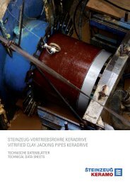
The horizontal thrust borer advances a steel casing tube,<br />
the ground being simultaneously broken down mechanically<br />
at the face by the cutting head and the extracted<br />
soil conveyed by augers (Fig. 5). The horizontal thrust<br />
borer is installed and braced precisely with respect to<br />
level and direction in the starting shaft. When the target<br />
shaft has been reached and the augers retracted the<br />
steel casing tubes are pressed into the target shaft and<br />
there removed, allowing an adaptor holding product<br />
pipes of the same bore being inserted.<br />
It sometimes happens that the location for the target<br />
shaft on the plot to be connected is for various reasons<br />
not yet available. To avoid the necessity for intermediate<br />
shafts in or close to the pavement in front of the plot, socalled<br />
blind shafts have been developed. As soon as the<br />
horizontal thrust borer reaches the target for the advance,<br />
the augers with cutting head are retracted and<br />
the product pipes inserted into the steel casing tubes<br />
Micro-tunnelling Page 9<br />
with stopped ends. Then, while the product pipes are<br />
retained, the steel casing tubes are retracted to the starting<br />
access shaft (Fig. 6). With careful matching the void<br />
formed between steel and product pipe can be kept so<br />
small that any setting is negligible; neither, because of<br />
their greater wall thickness, are any problems caused for<br />
the jacking pipes by the absence of lateral support.<br />
Sizeable voids should however be filled.<br />
The blind boring, providing the means of underground<br />
connection to existing collectors ≥ DN 300 or shafts,<br />
was developed some years ago by Bohrtec. Here, in addition<br />
to the horizontal thrust borer, a drill rod, diamond<br />
bit and special sealing element are needed. Once the<br />
thrust borer has reached the collector or shaft, augers<br />
and cutting head are retracted and the drill rod with diamond<br />
bit inserted. Drilling into the collector is monitored<br />
from inside by television camera. There the drill core too<br />
Starting shaft<br />
1. Boring<br />
Fig. 5: Non-controllable horizontal thrust boring<br />
Steel casing tube<br />
Thrust borer Screw conveyor<br />
2. After-pushing of product pipes<br />
Starting access hole<br />
1. Boring<br />
Cutting head<br />
Product pipe<br />
(jacking pipe)<br />
Steel casing tube<br />
Steel casing tube<br />
Adaptor<br />
Drill head<br />
Thrust borer Screw conveyor<br />
Product pipe<br />
Steel casing tube<br />
2. Insertion of product pipes<br />
Retaining assembly<br />
Stopper<br />
3. Retraction of steel casing tubes<br />
Target shaft<br />
Fig. 6: Non-controllable<br />
horizontal thrust boring:<br />
making a blind hole