mohring engels.indd - Keramo Steinzeug
mohring engels.indd - Keramo Steinzeug
mohring engels.indd - Keramo Steinzeug

You also want an ePaper? Increase the reach of your titles
YUMPU automatically turns print PDFs into web optimized ePapers that Google loves.
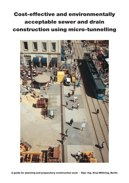
Cost-effective and environmentally<br />
acceptable sewer and drain<br />
construction using micro-tunnelling<br />
A guide for planning and preparatory construction work · Dipl.-Ing. Knut Möhring, Berlin
Cost-effective and environmentally<br />
acceptable sewer and drain construction<br />
using micro-tunnelling<br />
A guide for planning and preparatory construction work • Dipl.-Ing. Knut Möhring, Berlin<br />
Translated under the supervision of <strong>Keramo</strong>-<strong>Steinzeug</strong>, Paalsteenstraat 36, B-3500 Hasselt,<br />
from German into English, with the permission of Dipl.-Ing. Möhring
Contents<br />
1. Introduction . . . . . . . . . . . . . . . . . . . . . . . . . . . . . . . . . . . . . . . . . . . . . . 5<br />
2. The advantages of micro-tunnelling . . . . . . . . . . . . . . . . . . . . . . . . . . . 7<br />
3. Methods of micro-tunnelling . . . . . . . . . . . . . . . . . . . . . . . . . . . . . . . . . 9<br />
3.1 Non-controllable methods . . . . . . . . . . . . . . . . . . . . . . . . . . . . . . . . . . . . 9<br />
3.2 Controllable methods . . . . . . . . . . . . . . . . . . . . . . . . . . . . . . . . . . . . . . . . 10<br />
Pilot pipe jacking . . . . . . . . . . . . . . . . . . . . . . . . . . . . . . . . . . . . . . . . . . . 10<br />
Thrust-bore pipe jacking . . . . . . . . . . . . . . . . . . . . . . . . . . . . . . . . . . . . . 11<br />
Shield pipe jacking . . . . . . . . . . . . . . . . . . . . . . . . . . . . . . . . . . . . . . . . . . 13<br />
4. Selection criteria for jacking systems . . . . . . . . . . . . . . . . . . . . . . . . . . 15<br />
5. Micro-tunnelling applications . . . . . . . . . . . . . . . . . . . . . . . . . . . . . . . . 15<br />
5.1 The Berlin method . . . . . . . . . . . . . . . . . . . . . . . . . . . . . . . . . . . . . . . . . . 16<br />
5.2 Pipe eating . . . . . . . . . . . . . . . . . . . . . . . . . . . . . . . . . . . . . . . . . . . . . . . . 19<br />
6. Planning and preparatory construction work . . . . . . . . . . . . . . . . . . . . 20<br />
6.1 ATV Worksheet A 125 Pipe jacking . . . . . . . . . . . . . . . . . . . . . . . . . . . . . 20<br />
6.2 ATV Worksheet A 161 Structural design of jacking pipes . . . . . . . . . . . . . 21<br />
6.3 Standard rating books, rating range 085 pipe jacking . . . . . . . . . . . . . . . . 21<br />
6.4 DIN 18319 General technical contract terms for pipe jacking . . . . . . . . . . 21<br />
6.5 Obstacles . . . . . . . . . . . . . . . . . . . . . . . . . . . . . . . . . . . . . . . . . . . . . . . . 22<br />
6.6 Quality Safeguarding in Sewer Construction . . . . . . . . . . . . . . . . . . . . . . . 23<br />
7. Cost-effectiveness . . . . . . . . . . . . . . . . . . . . . . . . . . . . . . . . . . . . . . . . . 24<br />
7.1 Comparative cost of sewer construction: unpaved surface . . . . . . . . . . . 25<br />
7.2 Comparative cost of sewer construction: interlocking paving . . . . . . . . . 26<br />
7.3 Comparative cost of sewer construction: concrete paving . . . . . . . . . . . . 27<br />
7.4 Comparative cost of sewer construction: bitumen paving . . . . . . . . . . . . 28<br />
7.5 Comparative cost of house-connection sewers . . . . . . . . . . . . . . . . . . . . 29<br />
7.6 Social costs . . . . . . . . . . . . . . . . . . . . . . . . . . . . . . . . . . . . . . . . . . . . . . . 30<br />
8. Micro-tunnelling as an opportunity for lower sewage charges . . . . . . 30<br />
9. Recommendations for carrying out micro-tunnelling . . . . . . . . . . . . . . 31
Dipl.-Ing. Knut Möhring…<br />
…former manager of the Supply Networks division of<br />
Berliner Wasserbetriebe (BWB)<br />
Involvement in standardisation and trade-association activities<br />
(among others):<br />
– chairman of the ATV DVGW ”Trenchless Construction<br />
Techniques” working group<br />
– member of numerous study groups in the DIN Water<br />
Industry Standardisation Committee and of CEN Panels<br />
– member of ATV HA 1<br />
– former chairman of the DIN study group Vitrified Clay<br />
Pipes<br />
– former member of the Technical & Scientific Advisory<br />
Panel of the Vitrified Clay Industry Research Association<br />
– founder member and chairman for many years of the<br />
Quality Safeguarding in Sewer Construction<br />
Honours (among others):<br />
– ATV Golden Needle<br />
Dipl.-Ing. Knut Möhring<br />
Nikolaus-Bares-Weg 81<br />
12279 Berlin<br />
– Order of Merit of the Federal Republic<br />
1. Introduction<br />
Micro-tunnelling Page 5<br />
Methodical construction of the first generation of municipal<br />
sewage systems of the modern era began in the<br />
last century. Laid carefully, of good quality and at considerable<br />
cost in manual labour, many of those sewers<br />
and drains are still in use today.<br />
For a long time technical advances in sewer construction<br />
were only tentative, confined mainly to mechanisation<br />
of work on-site, soil excavation and the introduction<br />
of alternative techniques for lining utility trenches and<br />
shafts. Construction-site pictures from earlier decades<br />
show clearly that manual work predominated and that<br />
sewer construction was very labour-intensive. Clear<br />
economic advantages were obtainable only after tunnelling<br />
methods became possible in the construction of<br />
accessible sewers. This depended on high-grade pipes<br />
and joint assemblies together with efficient hydraulic<br />
pressing and conveying equipment in conjunction with<br />
reliable measurement and control systems. In particular<br />
where collecting-drains were needed at great depth below<br />
the water table significant savings could be made<br />
with these ”manned” thrust borings as against opentrench<br />
sewer construction. Such headings are routine<br />
today. Jacking-distances of over 1000 metres from a<br />
single starting shaft are just as possible as the driving of<br />
three-dimensional curves. Even differing geological<br />
conditions present no problems, since pipe- and shieldjacking<br />
systems are possible for accessible sewers in all<br />
loose and consolidated rock and in groundwater.<br />
With ”manned” thrust borings it is however essential to<br />
observe safety rules relating to minimum dimensions in<br />
the working-space in the pipe. In circular walk-through<br />
tunnels, galleries or headings<br />
for lengths up to<br />
50 metres 800 mm unobstructed internal diameter<br />
and for lengths over<br />
50 metres 1000 mm unobstructed internal diameter<br />
must be observed. Circular sections not meeting these<br />
requirements were deemed non-accessible. Today’s<br />
regulations under ATV Worksheet A 125 Pipe jacking,<br />
September 1996, stipulate for ”manned” pipe jacking a<br />
normal bore of 1,200 mm, which may in exceptional<br />
cases be reduced to 1,000 mm if<br />
– a jacking distance of 80 metres is not exceeded and
m<br />
350.000<br />
300.000<br />
250.000<br />
200.000<br />
150.000<br />
100.000<br />
50.000<br />
0<br />
Page 6 Micro-tunnelling<br />
– there is a linked working pipe (bore 1,200 mm) at least<br />
2,000 mm in length.<br />
A glance at German sewage systems shows them to<br />
consist predominantly of non-accessible cross-sections.<br />
It is apparent from ATV documents that some 80% of<br />
public sewers have a nominal size < DN 800. In Berlin,<br />
where approximately 77% of the sewer sections are part<br />
of the separate system, the proportion of nominal sizes<br />
≤ DN 800 even reaches about 90%.<br />
Private sewage systems in Germany, principally estate<br />
drains and house-connection sewers, are between<br />
700,000 and 1,000,000 km in length. The small nominal<br />
sizes predominate here.<br />
These figures account for the special interest of operators<br />
in underground construction methods for small and<br />
medium nominal sizes. Such an ”enclosed” construction<br />
method for making non-accessible sewers and<br />
drains can only be attained for the pipe cross-section to<br />
be installed by displacing or removing soil mechanically<br />
and generally requires a system of remote control.<br />
After a phase of subsidised research projects the ”enclosed<br />
construction method for non-accessible sections”<br />
came into increased use in Germany from about<br />
1984 onwards. On the basis of Japanese developments<br />
the Federal Government research funds deployed mainly<br />
in Hamburg provided the requisite impulse for<br />
progress in Germany too. The initial spark set technical<br />
advance in motion.<br />
At the outset remote-controlled and unmanned thrust<br />
boring was initially confined to the nominal sizes between<br />
DN 250 and DN 1,000 which were necessary for<br />
mechanical-engineering reasons and feasible. The designation<br />
”micro-tunnelling” was nevertheless correct.<br />
Technical development of unmanned remote-controlled<br />
thrust boring has however long since become established<br />
beyond DN 1,000 too; the micro-tunnelling<br />
Fig. 1: Growth of micro-tunnelling at BWB<br />
(cumulative curve)<br />
1983 1984 1985 1986 1987 1988 1989 1990 1991 1992 1993 1994 1995 1996 1997<br />
principle has now come to apply up to DN 1,600 and<br />
beyond, so that one may now speak of an unlimited upward<br />
trend. Its advantages in terms of occupational<br />
medicine are sufficient in themselves to sustain this<br />
trend towards even greater nominal sizes. For some<br />
time, however, thrust-boring systems have also been<br />
available which permit micro-tunnelling for nominal size<br />
DN 200 in sufficient length between manholes. To get<br />
round the lexical problems associated with the term ”micro”<br />
for large dimensions too, Worksheet A 125 Pipe<br />
jacking, September 1996 edition, distinguishes therefore<br />
between<br />
– pipe-jacking methods which operate unmanned<br />
and<br />
– pipe-jacking methods which operate manned.<br />
In the European Standard ”Trenchless laying and testing<br />
of drains and sewers” currently in preparation (now in<br />
draft form as pr DIN EN 12889) the term micro-tunnelling<br />
is used for unmanned remote-controlled jacking ≤ 1,000<br />
mm bore, albeit with the supplementary note that, owing<br />
to technical developments, greater nominal sizes can<br />
now also be jacked.<br />
The economic breakthrough in micro-tunnelling in Germany<br />
has been achieved by Berliner Wasserbetriebe<br />
(BWB) with the development of the ”Berlin method” and<br />
”pipe-eating”. Subsidies have been deliberately dispensed<br />
with here; the market has however been constantly<br />
challenged to tender for trenchless installation<br />
methods. Fig. 1 shows the development of micro-tunnelling<br />
in Berlin between 1984 and 1997 as a cumulative<br />
curve. The trend is still upwards. In the last few years<br />
micro-tunnelling’s share in the total length of sewers installed<br />
by BWB has averaged about 50%, in some cases<br />
even more.<br />
While controlled thrust boring of small pipe sections was<br />
not technically feasible attempts were made, especially<br />
in sewage projects with nominal sizes between DN 400<br />
and DN 800 at great depths and below the water table,<br />
to reduce construction costs by other means.<br />
Accessible sections have also been thrust-bored using<br />
compressed air and smaller product pipes meeting operational<br />
needs installed in them. These have been more<br />
cost-effective solutions than constructing sewers in<br />
open trenches with correspondingly expensive sheeting<br />
and soil excavation together with elaborate dewatering.<br />
In the long term – especially for even smaller nominal<br />
sizes – this twin-shell construction has not however<br />
been satisfactory, especially since at the time no other<br />
use could be made of the large void space between the<br />
two pipe sections.
2. The advantages of micro-tunnelling<br />
Pipe-jacking systems are distinguished by a high level of<br />
mechanisation and therefore require substantially less<br />
manual work than conventional open sewer construction.<br />
From the fact that thrust boring is possible with<br />
concentrated rather than linear construction sites as<br />
with open methods derive the many advantages, with in<br />
some cases substantial economic and environmentrelevant<br />
consequences.<br />
The surface is generally disturbed only at the starting,<br />
target and intermediate shafts or by-shafts. Breaking-up<br />
of the road surface and subsequent restoration with the<br />
associated disruption of traffic is thereby minimised.<br />
Previous relaying of other pipes or underground installations<br />
along or close to intersections with open utility<br />
trenches for sewer construction can be reduced. The<br />
starting shaft, normally covered by the thrust-boring<br />
container, guarantees that work is noise-free and independent<br />
of the weather.<br />
Because of local topography there are often hardly any<br />
differences in level between drainage areas; some<br />
sewers must then be laid at greater depths. With open<br />
construction greater depth is thus accompanied not only<br />
by costly trench sheeting but also by substantial soil<br />
excavation. In towns and densely-populated built-up<br />
areas the excavated soil can seldom be accommodated<br />
in the immediate vicinity of the construction sites, which<br />
may give rise to long transport distances with multiple<br />
loading and unloading. Frequently, too, the excavated<br />
soil cannot be put back again if the requisite degree of<br />
compaction in the road base cannot be attained with it.<br />
In many cases neither the broken-up roadway material<br />
nor the excavated soil may be removed for use at the<br />
contractor’s discretion; both may constitute building<br />
waste which must then be conveyed to listed landfill<br />
sites. Appropriate tests with evidence of suitability must<br />
be performed.<br />
Construction of utility trenches is very expensive anyway,<br />
and is made even more so by the aforementioned<br />
requirements. Calculation of the cost shares for constructing<br />
12,252 metres of DN 200 and DN 250 sewers<br />
in 14 construction projects in Berlin-Heiligensee and<br />
Tegelort in 1983 and 1984 at a figure of about DM 9.2<br />
million (excl. VAT) showed that, taken together, lining<br />
such trenches, excavating and transporting the soil, any<br />
necessary soil replacement, landfill charges incurred,<br />
backfilling and compacting the trench and removing the<br />
sheeting made up some 39% of the construction costs.<br />
About another 31% must go on breaking up and eventually<br />
restoring the road (Fig. 2). This means that,<br />
cumulatively, some 70% of the costs incurred in open<br />
construction have nothing to do with sewer installation<br />
proper and are thus economically questionable.<br />
■<br />
■<br />
■<br />
■<br />
■<br />
■<br />
■<br />
■<br />
■<br />
■<br />
■<br />
39 %<br />
6 %<br />
63 %<br />
Micro-tunnelling Page 7<br />
Fig. 2: Cost shares for DN 200 and DN 250 domestic/industrial<br />
sewer construction by open method<br />
3 % Site equipment<br />
8 %<br />
14 %<br />
31 %<br />
7 %<br />
31 % Breaking up and restoring road<br />
8 %<br />
3 %<br />
12 %<br />
39 % Sheeting, bridges, excavating and replacing<br />
soil, backfilling<br />
8 % Dewatering<br />
7 % Manholes<br />
12 % Sewers, junctions and laterals<br />
Fig. 3: Cost shares for DN 200 and DN 250 domestic/industrial<br />
sewer construction by enclosed method<br />
9 % Site equipment<br />
8 % Breaking up and restoring road<br />
9 %<br />
14 % Sheeting, bridges, excavating and replacing<br />
soil, backfilling<br />
6 % Dewatering<br />
63 % Sewers, junctions and laterals
Page 8 Micro-tunnelling<br />
Quite different cost relativities arise for the examples cited<br />
if sewers are constructed by a trenchless method.<br />
Interference with surface fixings is confined to the small<br />
number of shafts required for thrust boring. If cylindrical<br />
cross-sections are used, the area needed for these<br />
shafts is even smaller than when rectangular trenches<br />
are made for standard manholes leading into the sewers<br />
in accordance with the requirements of DIN 4124.<br />
Trenchless construction methods enable the cost share<br />
of about 31% in the projects referred to above for breaking<br />
up and restoring the road to be reduced to about 8%<br />
(Fig. 3). Shafts not being worked at or in are temporarily<br />
covered using precast slabs (Fig. 4) and are thus not<br />
an obstacle to traffic flow.<br />
Micro-tunnelling ensures high-quality construction. The<br />
jacking pipes have extremely low tolerances. They are<br />
top-quality products and have a reliably long service life,<br />
since they must withstand the special requirements and<br />
stress levels of thrust boring. Thrust boring gives rise to<br />
a largely undisturbed pipe support, and the machinery’s<br />
sophisticated control technology guarantees more precise<br />
routing than in conventional sewer construction.<br />
Micro-tunnelling also offers new approaches to overall<br />
planning of drainage areas. Underground sewers are<br />
made more expensive when installed at greater depths<br />
almost exclusively by the manhole structures, the actual<br />
thrust-boring costs being relatively independent of<br />
depth. The examples examined in the following observations<br />
on cost-effectiveness substantiate this. For<br />
overall planning the result is that drainage areas are less<br />
affected by local topography. They can be enlarged by<br />
placing sewers deeper and simultaneously dispensing<br />
Fig. 4: Thrust-boring site with<br />
temporarily covered starting<br />
and target shafts<br />
with pumping stations. Savings can be effected by this<br />
dispensing with the construction and operation of such<br />
pumping stations.<br />
Moreover, micro-tunnelling brings other economic, safety<br />
and ecological benefits:<br />
The ability of thrust-boring systems to function in<br />
groundwater enables dewatering to be dispensed with<br />
or confined to pumping-out of starting and target shafts<br />
sealed with an underwater concrete bedding proof<br />
against buoyancy.<br />
Frequent causes of accidents in sewer construction are<br />
flaws and faults in the sheeting of open trenches or pits.<br />
In thrust boring, the starting and target shafts, which<br />
generally consist of prefabricated reinforced concrete<br />
shafts or liner-plates, constitute completely safe working<br />
areas for the workers. On micro-tunnelling construction<br />
sites there has to date been not a single serious accident<br />
in Berlin. Adjacent structures been not been damaged,<br />
nor have road users been harmed in the vicinity of the<br />
few open shafts.<br />
Only micro-tunnelling makes simultaneous construction<br />
work feasible in all roads traversing a drainage area,<br />
since sufficient access for fire-engines and other emergency<br />
vehicles can always be guaranteed.<br />
Substantial ecological benefits result from reduced pollutant<br />
emission levels, limited disruption/diversion of<br />
traffic and from sparing grassed areas and trees, which<br />
can be harmlessly under-crossed.
3. Micro-tunnelling: methods<br />
ATV A 125 describes the currently practised methods of<br />
micro-tunnelling for unmanned pipe jacking.<br />
Non-controllable methods<br />
and<br />
controllable methods are distinguished.<br />
Because of the high requirements with respect to positional<br />
accuracy, under ATV A 125 Section 5 only controllable<br />
methods should be employed for thrust-boring<br />
sewers and drains. The figures shown below for maximum<br />
deviations in mm from the specified position (Table<br />
11 in A 125) should not be exceeded.<br />
DN vertical horizontal<br />
600 20 25<br />
600 bis 1000 25 40<br />
1000 bis 1400 30 100<br />
1400 50 200<br />
Max. deviation in mm from specified position for<br />
sewers and drains<br />
3.1 Non-controllable methods<br />
In constructing lareral sewers non-controllable horizontal<br />
thrust borers, used mainly for nominal size DN 150<br />
and limited jacking distances, are also employed. Given<br />
favourable local conditions and appropriate gradients,<br />
jacking distances below 20 metres are possible.<br />
The horizontal thrust borer advances a steel casing tube,<br />
the ground being simultaneously broken down mechanically<br />
at the face by the cutting head and the extracted<br />
soil conveyed by augers (Fig. 5). The horizontal thrust<br />
borer is installed and braced precisely with respect to<br />
level and direction in the starting shaft. When the target<br />
shaft has been reached and the augers retracted the<br />
steel casing tubes are pressed into the target shaft and<br />
there removed, allowing an adaptor holding product<br />
pipes of the same bore being inserted.<br />
It sometimes happens that the location for the target<br />
shaft on the plot to be connected is for various reasons<br />
not yet available. To avoid the necessity for intermediate<br />
shafts in or close to the pavement in front of the plot, socalled<br />
blind shafts have been developed. As soon as the<br />
horizontal thrust borer reaches the target for the advance,<br />
the augers with cutting head are retracted and<br />
the product pipes inserted into the steel casing tubes<br />
Micro-tunnelling Page 9<br />
with stopped ends. Then, while the product pipes are<br />
retained, the steel casing tubes are retracted to the starting<br />
access shaft (Fig. 6). With careful matching the void<br />
formed between steel and product pipe can be kept so<br />
small that any setting is negligible; neither, because of<br />
their greater wall thickness, are any problems caused for<br />
the jacking pipes by the absence of lateral support.<br />
Sizeable voids should however be filled.<br />
The blind boring, providing the means of underground<br />
connection to existing collectors ≥ DN 300 or shafts,<br />
was developed some years ago by Bohrtec. Here, in addition<br />
to the horizontal thrust borer, a drill rod, diamond<br />
bit and special sealing element are needed. Once the<br />
thrust borer has reached the collector or shaft, augers<br />
and cutting head are retracted and the drill rod with diamond<br />
bit inserted. Drilling into the collector is monitored<br />
from inside by television camera. There the drill core too<br />
Starting shaft<br />
1. Boring<br />
Fig. 5: Non-controllable horizontal thrust boring<br />
Steel casing tube<br />
Thrust borer Screw conveyor<br />
2. After-pushing of product pipes<br />
Starting access hole<br />
1. Boring<br />
Cutting head<br />
Product pipe<br />
(jacking pipe)<br />
Steel casing tube<br />
Steel casing tube<br />
Adaptor<br />
Drill head<br />
Thrust borer Screw conveyor<br />
Product pipe<br />
Steel casing tube<br />
2. Insertion of product pipes<br />
Retaining assembly<br />
Stopper<br />
3. Retraction of steel casing tubes<br />
Target shaft<br />
Fig. 6: Non-controllable<br />
horizontal thrust boring:<br />
making a blind hole
Fig. 7: Non-controllable<br />
horizontal<br />
thrust boring:<br />
blind hole with<br />
underground<br />
connection to a<br />
collector<br />
Page 10 Micro-tunnelling<br />
is removed. The lateral sewer made of DN 150 vitrified<br />
clay pipes is then drawn in. At the point of this rod is the<br />
special sealing element, which ensures proper connection<br />
of the product pipe to the collector. The steel casing<br />
tubes are then retracted and the void surrounding the<br />
product pipes filled with a special slag (Fig. 7).<br />
An alternative method of non-controlled thrust boring is<br />
underground drilling from a ≥ DN 1200 collector. A trolley<br />
can be brought to any drilling point in the collector<br />
and be set to the required angle of incline up to 90˚. Using<br />
adaptor and diamond bit, the collector is then bored<br />
through to the required external diameter. Subsequent<br />
drilling through the ground is performed with steel<br />
Starting shaft<br />
1. Boring<br />
2. Collaring<br />
casing tube and augers. When the thrust-bore target is<br />
reached, the augers are retrieved and the underground<br />
wall or inspection chamber drilled through with drill pipe<br />
and diamond bit. Finally the product pipe is inserted and<br />
the steel casing tube retracted while the product pipe is<br />
Fig. 8: Non-controllable horizontal<br />
thrust-boring: boring from<br />
a ≥ DN 1200 collector<br />
Steel casing tube<br />
Cutting head<br />
Thrust borer Screw conveyor<br />
3. Insertion of product pipes<br />
with special sealing element<br />
4. Retraction of steel casing tubes<br />
Collector<br />
Pipe Ø DN 1200 mm upwards<br />
retained. If there is adequate working space in the<br />
thrust-bore target, the product pipes can alternatively be<br />
pushed through afterwards and the steel casing tubes<br />
removed at the target (Fig. 8).<br />
3.2 Controllable methods<br />
For constructing sewers and drains three thrust-boring<br />
methods in particular have come to predominate in<br />
practice:<br />
pilot pipe jacking and<br />
thrust boring using steel joint heads and mechanical<br />
or hydraulic soil transport (auger orslurry conveying).<br />
Pilot pipe jacking<br />
In this process a steel pilot pipe, hollow and therefore<br />
having an optical channel, in sections normally of 100<br />
cm length and with an external diameter of about 10 cm<br />
is driven from a starting shaft to a target hole, compressing<br />
the soil. Directional accuracy is normally<br />
monitored by means of a theodolite with CCD camera<br />
located in the starting shaft and a diode panel fitted in<br />
the optical channel in the first pilot pipe. The position of<br />
the externally tapered first pilot drill pipe is continuously<br />
transmitted to a monitor in the starting shaft. If it deviates<br />
from the specified axis, the pilot drill rod is turned<br />
so that the angled head at the point of the string brings<br />
about a directional correction as it is further advanced.<br />
Accurate arrival of the pilot drill rod in the target shaft<br />
and its recovery there rod by rod are followed by an<br />
adaptor widening the cross-section to accommodate<br />
steel casing tubes with augers. The soil is conveyed to<br />
the starting shaft. When the steel tubes have reached<br />
the target shaft, the augers are retracted, an adaptor is<br />
inserted, the product pipes are pushed in behind and the<br />
steel casing tubes are recovered in the target shaft (Fig.<br />
9). Fig 10 shows the final phase of pilot pipe jacking using<br />
DN 150 vitrified-clay pipes.<br />
This method has proved itself over years for installing<br />
house connections up to 20 (max. 30) metres long. In<br />
loosely bedded soils without embedded rock two-phase<br />
application, i.e. without steel casing tube, is also sometimes<br />
practised.<br />
Numerous improvements in detail, especially in the<br />
coupling for the pilot pipes, have enabled this technique<br />
to be used for about two years now also for underground<br />
laying of DN 200 and DN 250 sewers with the section<br />
lengths normal in sewage systems. Like all pilot pipe<br />
jacking, however, this technique requires displaceable<br />
soil without substantial embedded obstacles. The pilot<br />
drill pipe has recently also become available in watertight<br />
form, so that with a modified screw-conveying
Fig. 9: Pilot pipe jacking<br />
system work below the water table is now also possible.<br />
The thrust boring of DN 200 sewers in section lengths<br />
which is now feasible is acquiring pre-eminent importance.<br />
The accurate underground driving of sewers of<br />
this nominal size at the customary section lengths was<br />
not possible earlier with the thrust-boring systems<br />
available on the market. From the inception of microtunnelling<br />
the conveying equipment to be incorporated<br />
inside the jacking pipe for moving the displaced soil, including<br />
protective tubing for cables, and the essential<br />
optical channel for the laser beam to control the advance<br />
determined nominal size DN 250 as the smallest crosssection<br />
of access-hole length drivable underground. For<br />
operators this meant that for constructing collectors<br />
they had to dispense with the customary smallest nominal<br />
size DN 200 if on economic grounds or because of<br />
compelling local factors enclosed construction methods<br />
had to be preferred to conventional sewer construction.<br />
Fig. 10: Pilot pipe jacking, final<br />
phase: after-pushing of the vitrified-clay<br />
pipe from a DN 2000<br />
starting shaft<br />
How widespread DN 200 is in the public sewage systems<br />
is shown by figures from the BWB’s combined and<br />
domestic/industrial sewage systems: some 32% of the<br />
BWB’s 8613-km long sewage system is of this nominal<br />
size. Particularly in the separate systems’ domestic/industrial<br />
sewage networks large parts of the drainage areas<br />
can be developed with DN 200 circular cross-sections<br />
and are hydraulically fully adequate for all operational<br />
requirements. If one considers the Berlin domestic/industrial<br />
sewage networks alone, DN 200’s share is<br />
as much as 65%. Because of this special importance<br />
operators have never abandoned the desire and requirement<br />
to be able one day, with improved technology, for<br />
controlled driving of DN 200 pipes too. This has now<br />
been made possible by the work of three German machinery<br />
producers in particular and provides planners<br />
and operators with other alternatives and the means of<br />
investing more economically since sewer construction is<br />
becoming more cost-effective.<br />
The requirements of ATV A 125, Section 6.2.2 governing<br />
the measuring and logging of runs of piping in the construction<br />
of jacking systems are met. During the jacking<br />
process, for example, the image on the monitor in the<br />
starting shaft can be continuously recorded by a videorecorder.<br />
All possible deviations are thus registered.<br />
Moreover, when product pipes are installed, the jacking<br />
pressure can be recorded by a pressure transducer with<br />
a memory by a recording manometer of the peak value<br />
in the measurement period.<br />
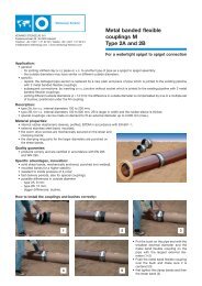
Thrust-bore pipe jacking<br />
Micro-tunnelling Page 11<br />
Here the product pipes are advanced at the same time<br />
as soil is displaced at the face by a cutting head. The<br />
soil is continuously conveyed to the starting shaft by<br />
augers. The augers are in a steel tube inside the jacking<br />
pipe. With each installed pipe the auger and pipe string<br />
is lengthened. The conveying pipes have skids and, like<br />
the augers, are adapted to the bore of the particular pipe<br />
to be jacked.<br />
In the starting shaft the soil is collected in a steel bucket<br />
during a jacking period and conveyed to the surface<br />
during the coupling operation. In this way the quantity<br />
of soil actually removed at the face is reliably monitored.<br />
An alternative to bucket extraction is to set up a sump in<br />
the starting shaft and convey by pumping. Fig. 11<br />
shows a thrust-boring container with a Soltau thrustbore<br />
pipe jacking system.<br />
Cutting head and augers are normally driven from the<br />
starting shaft. For heavy soils it is necessary to have<br />
available consistently high torque to comminute the<br />
drilled matter effectively. From DN 400 upwards pipejacking<br />
machines are therefore also offered with directly<br />
driven cutting head and separately driven augers.
Page 12 Micro-tunnelling<br />
Elements in the control system are the electronic target<br />
panel, the jacking laser and the hydraulically pivoted<br />
steel joint head with three control jacks. The laser unit is<br />
installed in the starting shaft independently of the abutment.<br />
This is very important, so that the laser’s alignment<br />
is not altered during thrust boring by movements of<br />
the abutment. For the same reason special care must be<br />
applied to making starting shafts or trenches stable and<br />
stationary. The laser beam gauged to the target shaft<br />
marks the planned position for the sewer. It strikes the<br />
electronic target panel fitted in the machine pipe (following<br />
the steel joint head), the so-called ”target”. The coordinates<br />
of the laser reception point and the roll and<br />
inclination of the control head are measured and the<br />
values transmitted to a display panel on the control<br />
console. The measured parameters are ultimately<br />
converted by a computer into control commands for the<br />
control jacks. These control actions take place automatically<br />
in short jacking periods, but can also be transmitted<br />
manually. A measurement log with all recorded<br />
parameters can be printed out for any period of time or<br />
distance. This also applies to the shield-jacking operations<br />
described below. Fig. 12 shows a log for such a<br />
thrust boring using a Herrenknecht AVN 700 shield jacking<br />
machine.<br />
Fig. 11: Thrust-bore<br />
pipe-jacking site on a<br />
public road<br />
Column 1: Dates<br />
Column 2: Time<br />
Column 3: Station in mm<br />
Column 4: Laser vertical in mm<br />
Column 5: Laser horizontal in mm<br />
Column 6: Rotaty cutter vertical in mm<br />
Column 7: Rotaty cutter horizontal in mm<br />
Column 8: Nick (slope) in mm/m<br />
Column 9: Gier (bearing) in mm/m<br />
Column 10: Roll in degrees<br />
Column 11: Torque in bar<br />
Column 12: Pressure in to<br />
Column 13: Cylinder left (Position) in mm<br />
Column 14: Cylinder upper (Position) in mm<br />
Column 15: Cylinder right (Position) in mm<br />
Column 16: Temperature in target panel in °C<br />
Column 17: Reference voltage (Target panel) in Volts<br />
Column 18: Zero voltage (Target panel voltage) in Volts<br />
Column 19: Laser amplitude (Target panel) in %<br />
Column 20: Laser diameter (Target panel) in mm<br />
1 2 3 4 5 6 7 8 9 10 11 12 13 14 15 16 17 18 19 20<br />
21.6.94 17:27:39 0,10 8 -1 -6 6 -1,3 -3,2 -1,2 102 3,0 0 0 0 28 3 0 1511 16<br />
21.6.94 17:49:02 0,20 9 -1 -4 8 -2,6 -4,9 -1,5 167 3,6 0 0 0 30 3 0 1451 18<br />
21.6.94 17:49:40 0,30 9 -1 -3 8 -3,3 -3,9 -1,3 132 2,5 0 0 0 30 3 0 1451 17<br />
21.6.94 17:51:10 0,40 8 -1 -3 8 -3,1 -2,9 -1,3 140 3,0 0 0 0 30 3 0 1491 19<br />
21.6.94 17:54:04 0,50 7 -3 -1 5 -5,2 -2,0 -1,5 174 4,1 0 0 0 30 3 0 1571 16<br />
21.6.94 17:54:08 0,60 6 -3 -1 3 -6,0 -2,0 -1,4 196 5,1 0 0 1 30 3 0 1591 15<br />
21.6.94 17:54:17 0,70 8 -3 -5 3 -7,7 -2,6 -1,5 152 3,1 0 0 1 30 3 0 1551 14<br />
Fig. 12: Specimen thrust-bore log
The application range generally covers nominal sizes<br />
between DN 200 and DN 1000 and jacking distances up<br />
to max. 100 metres in unconsolidated material. In cohesive<br />
soils of firm consistency extraction and conveying<br />
of the soil can be facilitated by adding water at the face.<br />
In water-bearing soils supplementary measures are<br />
necessary. For use in groundwater up to max. 1.50 but<br />
not more than 2.50 metres the face can be stabilised<br />
with compressed air. The first conveying pipes are for<br />
example fitted with modified augers with a shorter lead,<br />
so that soil plugs form which prevent the compressed air<br />
from escaping. Another possibility is to provide the<br />
starting and target shafts with locks and operate with<br />
compressed air. For this purpose a combined personnel<br />
and materials lock has proved effective which enables<br />
persons and materials to be got into the working area in<br />
separate pressurised chambers. The control console is<br />
installed over the jacking machine and outside the compressed-air<br />
chambers, so that working under atmospheric<br />
conditions is possible here. This compressed-air<br />
alternative is very costly and reserved for special cases.<br />
The method does however have two advantages: firstly,<br />
conveying with augers makes the separation system redundant,<br />
so that no special action is required in severe<br />
frost. Secondly, any recovery necessary at the face of<br />
obstacles to thrust boring and associated operations on<br />
the control head are possible with the compressed-air<br />
equipment available at the site, without need for elaborate<br />
dewatering.<br />
In view of the very successful two-/three-stage jacking<br />
systems using pilot rods and expansion boring in constructing<br />
house connections and nominal sizes for<br />
smaller collectors up to DN 400 a new thrust-bore pipe<br />
jacking system, first demonstrated by Bohrtec at Bauma<br />
’98, should be mentioned.<br />
It is based on two-phase thrust boring and is in initialcost<br />
terms an economical alternative to thrust-bore pipe<br />
jacking used hitherto to install sewers of nominal sizes<br />
between DN 400 and DN 800.<br />
In the first stage of the process a steel casing tube of external<br />
diameter 420 mm with internally fitted augers is<br />
jacked from a starting shaft with unobstructed width 320<br />
cm up to max. 60 metres to a target shaft. The augers<br />
have – like the pilot pipes – a hollow axis and, at the<br />
point of the screw line, a taper. Depending on the position<br />
of this oblique plane relative to the soil at the face,<br />
control movements can be executed during jacking.<br />
This principle of the so-called ”controlled auger” permits<br />
soil conveying also to be optimised with respect to embedded<br />
stone, since the entire cross-section of the steel<br />
casing tube is available for the purpose; the optical<br />
channel runs in the hollow axis of the revolving auger<br />
line, no longer above a separate conveying pipe in the<br />
clearance from the casing tube. Directional accuracy is<br />
again monitored by means of a theodolite with CCD<br />
camera and the monitor in the starting shaft and of the<br />
diode target panel in the control screw. The first stage in<br />
the process is carried out with the same equipment for<br />
all nominal sizes to be jacked and uses a clockwise-rotating<br />
screw line to transport the soil. When the control<br />
auger and first casing tube arrive at the target shaft, the<br />
second stage begins: an expansion stage with directly<br />
driven cutting head is docked on to the end of the line of<br />
steel tubes and, now turning anti-clockwise, conveys the<br />
soil encountered through the steel tube line of the first<br />
process stage to the target shaft. The size of the expansion<br />
stage depends on the nominal size of the<br />
product pipes (Fig. 13).<br />
Shield pipe jacking<br />
Micro-tunnelling Page 13<br />
Fig. 13: Two-phase thrust boring with control<br />
screw, augers and expansion stage, rotating<br />
clockwise and anti-clockwise<br />
Here thrust boring of the product pipes is accompanied<br />
by simultaneous all-over soil removal at the mechanically<br />
and fluid-assisted face by a directly driven cutting<br />
head which is rotating both clockwise and anticlockwise.<br />
In contrast to the machines using auger conveying, with<br />
slurry-conveying machines the soil is transported by a<br />
closed fluid circuit. As a rule the conveying medium<br />
used is water. For loosely bedded, non-cohesive unconsolidated<br />
material use of a bentonite suspension to<br />
prevent uncontrolled soil removal is appropriate. This<br />
type of machine thus lends itself well to coarse-grained<br />
soil types at any groundwater level.<br />
To operate the slurry system a feed pump, normally installed<br />
at ground level, and suction pump in the starting<br />
shaft are needed. By appropriately controlling the two<br />
pumps any pressure required at the face can be set and<br />
thus any water pressure counteracted. Crushers are incorporated<br />
in all slurry systems, so that extracted material<br />
is comminuted to an extent which ensures its subsequent<br />
blockage-free transport through the conveyor
Page 14 Micro-tunnelling<br />
pipe. Used in conjunction with suitable stoping tools,<br />
slurry systems lend themselves to working through even<br />
major obstacles, provided that such obstacles are firmly<br />
bedded in the soil and the angle of impact causes no deflection<br />
of the cutting head. If the cutting head is fitted<br />
with roller bits, thrust boring is possible even in hard rock<br />
and especially heavy soils (Fig. 14).<br />
Fig. 14: DN 800 rock<br />
cutting head with<br />
roller bits<br />
Fig. 15: Rear view of<br />
an AVN 800<br />
with target and<br />
supply pipes (Herrenknecht)<br />
The control technology is generally no different from that<br />
of thrust-bore pipe jacking described earlier. The range<br />
of application extends from DN 200 to far into the range<br />
of manned advances and accordingly also – depending<br />
on nominal size – to jacking distances up to several hundred<br />
metres. Fig. 15 shows the rear view of a Herrenknecht<br />
AVN 800 with target and supply pipes.<br />
All the micro-tunnelling systems mentioned are designed<br />
for low operating costs. For carrying out thrust boring<br />
alone three to four workers suffice. The extent of site<br />
equipment is not great and the equipment for the thrustboring<br />
process can be installed in relatively small<br />
starting shafts. Compact construction permits the machines<br />
including all units to be accommodated in steel<br />
containers suitable for on-site use. They are set up as<br />
static units with a bottom opening over the starting<br />
shaft. The container design not only optimises the<br />
space requirement, but also enables construction to proceed<br />
regardless of weather conditions. In Berlin thrustbore<br />
pipe jacking has been carried out from heated containers<br />
down to –20˚C. Open-method pipe laying, as is<br />
well known, becomes impossible in even slightly sub-zero<br />
temperatures and frozen ground. Companies with<br />
jacking equipment can therefore earn at normally income-less<br />
times of year. In so doing they promote yearround<br />
working in the construction industry and contribute<br />
to relieving the employment market.<br />
Fig. 16: Soltau mobile thrustboring<br />
unit<br />
As an alternative to static thrust bore containers mobile<br />
units are also available in which the construction gear is<br />
mounted on a trailer gantry. This permits rapid movement<br />
between sites without low-loaders and makes<br />
micro-tunnelling solutions economic even for short jacking<br />
distances and small sites. In this version diesel<br />
generating sets provide complete independence from<br />
the public electricity mains (Fig. 16).
4. Selection criteria for jacking<br />
systems<br />
As soon as different systems are available on the market<br />
the question of which it is advisable to use for which<br />
purpose arises. There is no single answer to this<br />
question since all systems have both advantages and<br />
disadvantages, the scope for use is wide and the constraints<br />
in problem definitions are often very complex.<br />
It is important that the promoter/client provides potential<br />
contractors with not only a comprehensively documented<br />
unambiguous plan but also, specifically, the most<br />
exact possible and sufficient data on the geology and<br />
soil mechanics of the line to be followed by the sewer<br />
and on the groundwater conditions. The decision on the<br />
jacking system to be used should – for purposes of<br />
rational spreading of risks – ultimately be left to the<br />
bidder, i.e. the subsequent construction company.<br />
Capital outlay for thrust-bore pipe-jacking systems is<br />
lower. They need less space and personnel, yielding<br />
time saving of up to 35% over shield jacking systems for<br />
setting-up the site.<br />
The following two tables analysing advance rates<br />
attained, including set-up time, yield further information.<br />
The first comparison shows a distinct decline in average<br />
advance rates for thrust-bore pipe-jacking systems as<br />
nominal size increases. For > DN 500 they drop to about<br />
66% / 71% of the rates attained for DN 250.<br />
In contrast, with shield pipe jacking, i.e. with hydraulic<br />
conveying, advance rates including set-up time are<br />
found to be more-or-less independent of nominal size.<br />
BWB: thrust-bore pipe jacking, average<br />
advance per 8 hours in metres<br />
Advance Advance<br />
with set-up time<br />
DN 250 9,93 6,08<br />
DN 300 8,61 5,20<br />
DN 400 8,32 4,91<br />
DN 500 8,46 5,00<br />
>DN 500 6,58 4,34<br />
The analyses relate to approximately 167,000 metres’<br />
total advance up to the end of 1994 in Berlin. It should<br />
be noted that the figures naturally reflect all local<br />
constraints, but also the skill and motivation of the personnel<br />
on site and the whole ethos of the executing<br />
company.<br />
Micro-tunnelling Page 15<br />
BWB: Shield pipe jacking, average advance<br />
per 8 hours in metres<br />
Advance Advance<br />
with set-up time<br />
DN 250 10,83 6,19<br />
DN 300 9,82 5,41<br />
DN 400 11,22 6,52<br />
DN 500 11,91 6,69<br />
DN 600 10,82 6,30<br />
DN 800 11,01 6,00<br />
DN 1000 11,65 6,71<br />
DN 1200 11,99 7,23<br />
The trend towards distinctly higher rates with shield pipe<br />
jacking systems at nominal sizes DN 400 is however<br />
conspicuous. This is partly due to the fact that at larger<br />
nominal sizes continuous transport of soil by flush-conveying<br />
is clearly superior to that using buckets. Moreover,<br />
the higher extraction and comminution rate has<br />
particularly beneficial effects where the ground is difficult.<br />
The constantly direct drive of the cutting head, the<br />
smaller losses compared with auger drive and the possibility<br />
thus afforded of driving greater lengths also make<br />
themselves felt in favour of auger systems.<br />
Selection of a jacking system with the particular<br />
extracting tools needed is however most strongly<br />
influenced by the geological conditions and groundwater<br />
level. See in this connection a publication by W. Becker<br />
(Berlin) on ”Scope and limits of micro-tunnelling taking<br />
extraction tools into account” (offprint from the journal<br />
”Tiefbau” , Vol. 7/1996, obtainable from <strong>Steinzeug</strong><br />
GmbH, Max-Planck-Strasse 6, 50858 Cologne). Taking<br />
as its basis the soil classifications of the General Technical<br />
Contract Terms (ATV), DIN 18319, VOB Part C, this<br />
article makes recommendations on selecting suitable<br />
jacking systems.<br />
5. Micro-tunnelling applications<br />
With the jacking systems available on the market construction<br />
orders for all nominal sizes used in sewage<br />
systems for both extension and renewal purposes are<br />
possible. Oval cross-sections too, which are enjoying<br />
something of a renaissance in waste-water engineering<br />
by virtue of their hydraulic advantages, can be jacked<br />
underground. Their external profile must of course have<br />
a circular cross-section, and precise adherence to the<br />
pipeline invert must be ensured. This requires roll-free<br />
jacking, which can be achieved if adjacent pipes are<br />
joined with shearing pins and machines with flush-conveying<br />
and thus cutting heads rotating clockwise and<br />
anti-clockwise are used.
Page 16 Micro-tunnelling<br />
The following tasks can be handled:<br />
– Underground making of connecting drains and house<br />
connections as blind-hole borings or with starting and<br />
target shafts. The starting shaft may be either above<br />
the collector or on the plot.<br />
– Underground making of house connections with<br />
underground connection to collectors.<br />
– Underground installation of sewers to extend sewage<br />
systems.<br />
– Underground installation of sewers and house connections<br />
by a cyclical method (the Berlin method).<br />
– Replacement of sewers by underground construction.<br />
Until the changeover the old sewers serve to keep the<br />
system operating. The Berlin method can also be applied<br />
to sewers and house connections in need of<br />
replacement, possibly in conjunction with pipe eating.<br />
– Underground replacement of sewers by replacing<br />
damaged sections (pipe eating).<br />
– Underground cutting of a sewer no longer needed in<br />
its original cross-section and previously filled with<br />
packing.<br />
5.1 The Berlin method<br />
The starting point was the concern to reduce digging-up<br />
of the road. If thrust boring is decided on only when the<br />
public sewer is constructed, while the house connections<br />
it serves are made by the open method, the result<br />
is a perforation of the surface vertical to the road axis for<br />
every single connection. In the light of today’s technical<br />
possibilities such a procedure is inadequate. A remedy<br />
is provided by the Berlin method, which comprises<br />
consistent application of controlled pipe jacking for collectors<br />
and feeder-sewers in a cyclical process (Fig. 17).<br />
In it for nominal sizes ≤ DN 800 prefabricated cylindrical<br />
starting and target shafts with internal diameter 2000 /<br />
3200 mm and jacking pipes with nominal length 1000<br />
and 2000 mm are used. Fig. 18 shows a 3.20-metre<br />
wide starting shaft with shield pipe jacking of DN 500 vitrified-clay<br />
pipes.<br />
Fig. 17: The Berlin method<br />
Berliner Wasserbetriebe<br />
Drainage Network Dept.
Fig. 18: Starting shaft<br />
(3.20 metres) with shield jacking<br />
of DN 500 vitrified-clay pipes<br />
For nominal sizes greater than DN 800 rectangular shafts<br />
must generally be dug. Alternatives for all nominal sizes<br />
are starting shafts of reinforced shotcrete, which lend<br />
themselves well to confined spaces, or the ONE-PASS<br />
SHAFT LININGS from England. The latter are prefabricated<br />
concrete tubbings which can be assembled on<br />
site, are available in a variety of bores from 1.52 to 10.67<br />
metres and are reusable.<br />
The shafts needed for thrust boring road sewers are also<br />
the starting point for thrust boring house connections,<br />
which are thrust bored to the plots in a radial way. If the<br />
shafts are arranged carefully according to local conditions,<br />
several plots can be reached from one shaft without<br />
any overlength arising for the particular house connection<br />
or need to tunnel under other plots.<br />
In the Berlin method type I the plots which cannot be<br />
reached from the starting or target shafts are<br />
accessed – also radially – from sunk ”by-shafts”. In the<br />
by-shaft the feeder-sewers are linked to the collector by<br />
backdrops and fittings. If the collector is above the<br />
groundwater, the by-shaft is sunk using liner-plate rings<br />
after thrust boring of the collector has been completed<br />
and retracted for re-use when the house connections<br />
have been constructed (Fig. 19). If the collector is in the<br />
groundwater, prefabricated reinforced-steel shafts are<br />
used for the by-shafts and sunk before any thrust boring<br />
starts. Like the starting and target shafts, they are<br />
sealed watertight under pressure under the sewer bottom<br />
with an concrete seal preventing buoyancy.<br />
Micro-tunnelling Page 17<br />
Pipe jacking then takes place through prepared apertures<br />
with collar seals against the pressing groundwater<br />
from the starting to the target shaft, through the byshafts<br />
which remain in the soil (Fig. 20). In the final cycle<br />
the starting and target shafts are finished as manholes<br />
with the usual dimensions.<br />
In the Berlin method type II the ”by-shafts” are replaced<br />
by additional starting, target or intermediate shafts<br />
linked radially to the house connections; when construction<br />
is completed, these become ordinary manholes into<br />
the sewer system (Fig. 17). This version meets the requirement<br />
in ATV A 142 that in Protected Zone II waterprocurement<br />
areas all feeder-sewers must be -connected<br />
to access-hole structures.<br />
The usual alternatives for finishing/converting the<br />
starting, target and intermediate shafts as/to ordinary<br />
manholes into the sewers are evident from Fig. 17 in<br />
conjunction with the diagrams in Fig. 21 to 23.<br />
Fig. 19: Berlin method: by-shaft above groundwater table
Fig. 20: Berlin method: by-shaft below groundwater table Fig. 21: Berlin method: starting/target shaft finished as manhole<br />
Fig. 22: Berlin method: starting / target shaft with manhole (concrete polymer) Fig. 23: Berlin method: starting / target shaft with manhole (DIN 4034 concrete)
Fig. 24:<br />
Pipe eating<br />
In addition to the shaft-to-shaft alternative other solutions<br />
are conceivable. There is a broad field here which<br />
should be exploited by innovative and complex solutions<br />
taking account of subsequent use, since manhole<br />
structures remain – and especially so in thrust boring –<br />
relatively high-cost facilities in which further savings<br />
must surely be possible.<br />
Radiating thrust boring of the connecting sewers and<br />
bringing them into the manholes permits the lowest possible<br />
depth, mostly above the water table. On the other<br />
hand, backdrops in the manhole are necessary, which<br />
however permit changes in the direction of flow and thus<br />
ensure hydraulically sound connection of drains arriving<br />
at acute angles to the collector’s direction of flow.<br />
In addition to the economic advantages, bringing feeder<br />
sewers close to manholes also has a number of operational<br />
ones, in particular because there are openings at<br />
both ends of the pipe, facilitating cleaning and inspection.<br />
Because sealing is technically straightforward, water-permeability<br />
tests can be performed rapidly and reliably.<br />
A feeder-sewer constructed in this way can later<br />
be straightforwardly rehabilitated by re-lining. Another<br />
advantage is that the composition of the sewage from<br />
each plot can be separately checked. There are moreover<br />
no fittings in the sewer section: this means less incidence<br />
of damage in the future, since surveys of the<br />
sewage system currently show that most damage occurs<br />
at junctions within the section.<br />
5.2 Pipe eating<br />
Initial successes with micro-tunnelling in Germany immediately<br />
prompted the thought that this technique<br />
might also be applied for replacements in the line of the<br />
old sewer, i.e. sewers needing replacement could be<br />
overlaid with new jacking pipes. This technique makes<br />
it unnecessary to search for a line for the sewer in the<br />
cross-section of roads already carrying much. At the<br />
same time a larger, more capacious sewer cross-section<br />
is obtained, a need which applies to many old sewers.<br />
An advantage over many other sanitation methods is<br />
Micro-tunnelling Page 19<br />
moreover that overlaying yields a high-quality new sewer<br />
with correspondingly long service life. The joint interests<br />
of operators, contractors and machine builders led<br />
to the following technical development of ”pipe eating”:<br />
– The basic features of thrust-boring and shield pipejacking<br />
machines remain; the steel joint heads and<br />
extracting tools are modified for the new task. Both<br />
auger and slurry conveying is suitable. In order not to<br />
interrupt the flush-conveying circulation the sewer to<br />
be replaced must either first be filled or a sealing<br />
packing system sent ahead of the cutter head.<br />
– All unreinforced sewer or pipe materials can be<br />
crushed and removed via the conveying system.<br />
– It is possible to use any commercially available<br />
jacking pipes.<br />
– The excentric pipe jacking needed for maintaining the<br />
invert incorporation of individual sewer sections in<br />
need of replacement and lateral and vertical alterations<br />
to the sewer position as found are made -possible<br />
by precise controllability.<br />
To facilitate fault-free construction and be able to lay a<br />
high-quality new sewer, the following preparations for<br />
pipe eating must be conscientiously carried out:<br />
Before pipe eating starts the existing junctions are cut<br />
off and the waste water present pumped over using<br />
lifting equipment. Discharge over a sewer section to be<br />
replaced must also be maintained by appropriate<br />
by-pass pipes or temporary diversions.<br />
Of particular importance is a preliminary clear-cut survey<br />
to detect any tilting in the sewer to be replaced, so that<br />
the new sewer cross-section receives proper support. If<br />
tilting is excessive, special measures must be taken. A<br />
larger pipe cross-section can for example be driven, or<br />
laying the whole section deeper or localised backfilling<br />
considered. The prior sewer survey must include the<br />
feeder-sewers. If their condition is still good, they can<br />
be reconnected later at the same point. If however the<br />
connecting sewers must also be replaced, pipe eating in<br />
conjunction with the Berlin method is available, i.e. radial<br />
connection to the shafts. Fig. 24 shows a pipe-eating<br />
operation in Berlin; here an approximately 100-year-old<br />
vitrified-clay DN 180 section is being replaced invertconform<br />
with DN 250 vitrified-clay jacking pipes.<br />
A higher level of wear, a slower rate of advance and<br />
expenditure on maintaining discharge for house connections<br />
and parts of the system above the installation site<br />
make pipe eating more expensive than normal pipe<br />
jacking. In replacement projects it is therefore generally<br />
more cost-effective – provided there is a free line available<br />
in the road’s cross-section – to drive a new sewer<br />
there and use the old one for temporary maintenance of
[m]<br />
8.000<br />
7.000<br />
6.000<br />
5.000<br />
4.000<br />
3.000<br />
2.000<br />
1.000<br />
Page 20 Micro-tunnelling<br />
discharge. Given the ever more confined underground<br />
space in conurbations and on industrial sites and for<br />
special applications, however, pipe eating has now<br />
become indispensable. Fig. 25 gives information about<br />
the frequency with which pipe eating has been employed<br />
at BWB in comparison with laying of replacements.<br />
BWB – Micro-tunnelling: Replacement methods compared<br />
1984 1985 1986 1987 1988 1989 1990 1991 1992 1993 1994 1995 1996 1997<br />
■ replacement laid in new position<br />
■ pipe-eating<br />
Fig. 25: Laying of replacements and<br />
pipe eating compared<br />
6. Planning and preparatory<br />
construction work<br />
Planning, design, tendering, preparatory construction<br />
work, execution and settlement of accounts for pipe<br />
jacking are governed by the general Standards and by<br />
the following special technical Standards, which must be<br />
complied with:<br />
– ATV Worksheet A 125 Pipe jacking, September 1996<br />
– ATV Worksheet A 161 Stress analysis of jacking pipes,<br />
January 1990<br />
– Standard rating books for the construction industry,<br />
rating range 085 pipe jacking, March 1997<br />
– DIN 18319 General technical contract terms for pipe<br />
jacking, VOB, Part C June 1996<br />
Additionally, account must be taken of the relevant quality<br />
and testing regulations of April 1998 of Quality Safeguarding<br />
in Sewer Construction (”Association for Quality<br />
in Sewer and Drain Construction and Maintenance”).<br />
6.1 ATV Worksheet A 125 Pipe jacking<br />
A guide for specialists working in planning and execution<br />
is ATV Worksheet A 125 Pipe jacking already cited<br />
several times. In two sections it describes all unmanned<br />
and manned pipe-jacking methods and their range of<br />
application. In the section on structures and machinery,<br />
jacking pipes & joint assemblies and shafts specific requirements<br />
made of jacking pipes of all materials and<br />
their joint assemblies are formulated in a technical Standard<br />
for the first time. Especially important here are the<br />
permitted tolerances for pipes with respect to nominal<br />
length, rectangularity of pipe ends, deviations from<br />
straightness, external pipe diameter and invert conformity.<br />
The general requirements for joint assemblies<br />
relate to, amongst other things, impermeability, deflection,<br />
resistance to shear force, transmission of longitudinal<br />
forces and sealing of gaps. The aim is to take these<br />
requirements of jacking pipes into account in relevant future<br />
materials standards. With EN 295-7 Vitrified-clay<br />
pipes and fittings, joint assemblies for sewers and<br />
drains, Part 7: Requirements made of vitrified-clay pipes<br />
and joints in pipe jacking, German edition DIN EN 295-7:<br />
1993, now introduced in all member countries, this has<br />
already happened very early in parallel with work on<br />
A 125 and even at European level.<br />
[m]<br />
60.000<br />
50.000<br />
40.000<br />
30.000<br />
20.000<br />
10.000<br />
BWB – Micro-tunnelling: Relative quantities of materials in jacking<br />
pipes<br />
1984 1985 1986 1987 1988 1989 1990 1991 1992 1993 1994 1995 1996 1997<br />
■ fibre cement ■ vitrified clay<br />
■ reinforced concrete ■ other<br />
Fig. 26: Relative quantities<br />
of materials in jacking pipes<br />
compared
Fig. 26 shows the relative quantities of materials in the<br />
jacking pipes used by BWB in Berlin.<br />
A section on preparatory planning includes amongst<br />
other things the maximum deviations from the specified<br />
position and requirements made for assessment of all<br />
existing structures and installations, subsoil and groundwater<br />
conditions and data on settings. The declaration<br />
of preferred nominal sizes is intended to support the<br />
rationalisation already brought about in the market with<br />
respect to limiting the number of jacking heads but also<br />
to stock-keeping of pipes. The section on execution<br />
calls for specialist companies and jacking logs with the<br />
parameters relevant to individual jacking operations.<br />
Additionally, extraction and conveying of soil, entries<br />
and exits, pumps, supporting and sliding means are<br />
treated. Special sections include the specific requirements<br />
for jacking under Deutsche Bundesbahn AG<br />
track, under federal highways and waterways. References<br />
facilitate the search for further standards and<br />
regulations.<br />
6.2 ATV Worksheet A 161 Stress analysis of<br />
jacking pipes<br />
Worksheet A 161 spells out what loads are to be considered<br />
for jacking pipes in the different phases and the<br />
procedures for measurement and safety certification. A<br />
distinction must be made between:<br />
construction state: stress in the pipe axis<br />
stress across pipe axis<br />
operating state: stress across pipe axis<br />
demonstration of<br />
fatigue-strength<br />
minimum measurement: stress caused by secondary<br />
bending moment<br />
Pipe producers are generally willing to prepare the stress<br />
analyses for jacking pipes and have for this purpose prepared<br />
forms for their customers on which both the local<br />
constraints and the particular jacking parameters should<br />
be entered.<br />
6.3 Standard rating books, rating range 085<br />
(pipe jacking)<br />
Tender specifications for the standard rating range (pipe<br />
jacking) enable all jacking methods covered in A 125 to<br />
be translated into specific tender specifications. The<br />
standardised texts specify performance so clearly and<br />
exhaustively that prices can be reliably calculated. This<br />
provides at the same time the basis for awarding contracts<br />
for jacking services and settling accounts for them<br />
automatically. The texts meet the requirements of the<br />
VOB and technical standards. With electronic data-processing<br />
the modular structure of the texts of all standard<br />
rating books enable the required text combinations to be<br />
assembled quickly and, additionally, to be exchanged on<br />
data media between clients, consultant engineers and<br />
contractors. This facilitates scrutiny of tenders and<br />
comparison of prices and enables price files holding<br />
average prices to be set up. This is an effective contribution<br />
to rationalising the construction industry which<br />
simplifies the work involved in awarding contracts and<br />
settling accounts and could also lead to an increase in<br />
the acceptability of pipe jacking. Pipe jacking has in the<br />
past often not happened because the agencies concerned<br />
experienced difficulties in formulating specifications<br />
for it. The standard rating book is structured as follows:<br />
– site equipment for pipe jacking<br />
– starting, target and intermediate shafts<br />
– jacking pipes, pipe jacking<br />
– pipe jacking in special fields, allowances for pipe<br />
jacking, safety precautions<br />
– planning of support structure and special equipment<br />
– preservation of evidence<br />
– survey work, as-built plans<br />
– measuring, monitoring points<br />
– documentation<br />
– recycling, disposal<br />
Micro-tunnelling Page 21<br />
6.4 DIN 18319 General Technical Contract<br />
Terms for Pipe Jacking Work<br />
If the VOB are agreed to for a construction contract, any<br />
pipe jacking work arising should be specified in accordance<br />
with the General Technical Contract Terms in Part<br />
C of the VOB (DIN 18319). Their validity covers all the<br />
methods here described. They do not cover earthworks<br />
for making shafts or trenches or removal of soil. Work on<br />
trench sheeting, in connection with pumping and other<br />
pipe laying should also be included separately in the<br />
specification.<br />
The soil classifications reflect the special features of<br />
jacking. There are
Page 22 Micro-tunnelling<br />
– 6 classes for non-cohesive unconsolidated material<br />
63 mm particle size with sand and gravel as main<br />
constituents, according to their compactness (loose,<br />
medium-dense, dense) and particle-size distribution<br />
– 6 classes for cohesive unconsolidated material 63<br />
mm particle size with silt, clay or sand, gravel with<br />
high proportions by mass of silt and clay as main constituents,<br />
according to consistency (slurry-soft, stiffsemi-rigid,<br />
rigid)<br />
– 4 additional classes for unconsolidated material with<br />
particle size > 63 mm, depending on proportion by<br />
mass of the stones and their size<br />
– 8 classes for consolidated rock, depending on its unconfined<br />
compression strength and interfacial spacing<br />
– other materials (e.g. mining waste dumps or under<br />
refuse dumps)<br />
This detailed classification system takes account of the<br />
contractor’s need for precise information about the<br />
ground for selecting the jacking method and costing.<br />
The tender specification for jacking work must include<br />
the following:<br />
Erection and backfilling the starting and target shafts,<br />
supplying the pipe material,<br />
the jacking operations, separated according to nominal<br />
size and soil classes,<br />
recovering obstacles,<br />
keeping jacking logs as required under A 125,<br />
transporting soil away.<br />
6.5 Obstacles<br />
Despite the technical advances in cutting through stone<br />
and breaking it down with integral crushers and in continuous<br />
conveying, an accumulation of unexpected<br />
obstacles always slows thrust boring down. In bad<br />
cases obstacles must moreover be recovered, which<br />
sometimes involves directional adjustment of the control<br />
head at the same time. These are special risks in thrust<br />
boring, which increase in inverse proportion to the<br />
nominal size. Interbedded rock is however also – if the<br />
local compactness permits – either displaced to the side<br />
or pushed along at the face. If large rocks are not<br />
engaged centrally, there is also danger of the control<br />
head being diverted.<br />
There are as yet no reliable methods of locating with sufficient<br />
accuracy at the planning stage rock obstacles for<br />
the defined area of the cross-section to be driven. It is<br />
therefore important to keep on drawing attention to the<br />
fact that for risk-apportionment purposes the project<br />
promoter should be regarded as the owner of the<br />
ground. He must analyse geological maps at the planning<br />
stage and should carry out ”historical searches” on<br />
the local situation. Site surveys must include the requisite<br />
information and parameters for the stress analysis<br />
and jacking listed in A 161 and A 125. The results of<br />
exploratory drilling should be presented as per DIN 4022<br />
as drilling logs and driving diagrams as far as possible in<br />
longitudinal sections through the subsoil. All these<br />
records yield however information which is, strictly<br />
speaking, valid for only one point. Previously undetected<br />
intercalation must however be expected, so that tender<br />
specifications should include statements about the<br />
accounting arrangements. DIN 18319 logically stipulates<br />
that the means by which rocks constituting an obstacle<br />
to jacking operations are to be eliminated must be<br />
specified jointly, i.e. there should be a section in the<br />
specification dealing with recovery of obstacles. The<br />
size of rocks constituting obstacles should be defined in<br />
this section. In Berlin the following procedure has been<br />
found effective:<br />
Trial drillings, driven and/or static soundings and analyses<br />
of them are generally performed at intervals between<br />
50 and 100 metres in the area of the planned line and<br />
form part of the tender specification. Selection of the<br />
jacking system is generally the prerogative of the bidder.<br />
In his tender he must however state the system selected<br />
and define the obstacle size at which crushing and conveying<br />
by the machinery becomes impossible. The<br />
trenches needed for recovering obstacles above this diameter<br />
and the standby costs incurred during recovery<br />
are paid separately. This is effected by the client setting<br />
out on the basis of empirical values a certain number of<br />
recovery trenches of appropriate sizes, depths and<br />
types of sheeting and the contractor then specifying<br />
prices for them. In this way obstacle elimination with<br />
provision of the jacking equipment is made competitive.<br />
Jacking costs can thus be estimated with less risk and it<br />
is easier for the client to examine tenders.<br />
Missing or deficient subsoil surveys in conjunction with<br />
incomplete or absent tender specifications are constantly<br />
leading to problems, breakdowns and disputes in the<br />
course of construction. The result is often that all concerned<br />
are angry and disappointed and quite wrongly<br />
take long-term leave of micro-tunnelling. This is why the<br />
planning, tender-specification and preparatory stages<br />
are more important in enclosed construction methods<br />
than in conventional sewer construction.<br />
As mentioned earlier, jacking of smaller nominal sizes in<br />
obstacle-rich and heavy soils can be problematic. If<br />
economically justifiable relative to other solutions, to reduce<br />
the risk of interruptions the use of a twin-shelled<br />
version is also usual in such cases; first a fairly larger and
high-capacity jacking pipe – e.g. DN 500 – is jacked<br />
using a stronger jacking system and the operationally<br />
necessary smaller piping then accommodated in it.<br />
Alternatively a so-called ”composite pipe” can be used.<br />
It consists of an inner pipe of the operationally necessary<br />
nominal size and a variable concrete or steel casing.<br />
Fig. 27 shows such a DN 400 / external diameter 860<br />
mm vitrified-clay/reinforced concrete jacking pipe.<br />
Fig. 27: Vitrified-clay /<br />
reinforced concrete<br />
jacking pipe<br />
6.6 Quality Safeguarding in Sewer<br />
Construction<br />
Under A 125 only specialist companies having experienced<br />
personnel and appropriate equipment may be entrusted<br />
with pipe jacking. Capability is deemed proven<br />
if the company holds an appropriate certificate from the<br />
quality partnership ”Quality Safeguarding in Sewer Construction”.<br />
The quality and testing stipulations include<br />
for micro-tunnelling the two assessment groups V3 and<br />
V2:<br />
V3 covers trenchless construction of sewers and<br />
drains in all materials ≤ DN 250.<br />
V2 covers trenchless and unmanned construction of<br />
sewers and drains in all materials and nominal sizes<br />
using controllable pipe jacking systems with automatic<br />
recording of jacking loads and continuous<br />
recording of positional deviation.<br />
In the General and Specific Requirements and with<br />
respect to companies’ equipment special experience<br />
and reliability of the companies and personnel deployed<br />
and controllable pipe jacking plant are required,<br />
amongst other things, in the quality and testing stipula-<br />
tions for both groups. The requirements must also be<br />
met by subcontractors.<br />
In April 1998 Quality Safeguarding in Sewer Construction<br />
listed for assessment group<br />
V2 72 certified firms and<br />
V3 49 certified firms.<br />
Micro-tunnelling Page 23<br />
Another 19 applications were to hand. Clients have thus<br />
a wide choice of competent firms, facilitating the necessary<br />
competition. In keeping with the requirements of A<br />
125 and proficient performance, clients should incorporate<br />
in the supplementary contract terms the following<br />
text conforming to VOB:<br />
Bidders must provide proof of the requisite specialist<br />
skill, operative capability and reliability and also a<br />
quality-assurance system comprising outside and self<br />
monitoring. The requirements of RAL quality and the<br />
GZ 961 testing rules must be fulfilled. Proof is<br />
deemed given if the company holds the appropriate<br />
RAL Quality Mark of the quality partnership ”Quality<br />
Safeguarding in Sewer Construction”. Alternatively<br />
an outside monitoring agreement for the individual<br />
operation concerned may be submitted; the requirements<br />
of the RAL quality and testing rules must be<br />
met.<br />
Because of the difficulty of thrust-boring operations their<br />
requirements are quite exceptional, including relevant<br />
knowledge possessed by only a limited number of sewer-construction<br />
companies. A glance at the number of<br />
certificates awarded in the last 10 years – since the quality<br />
partnership ”Quality Safeguarding in Sewer Construction”<br />
was formed – substantiates this. 1236 certifications<br />
for the assessment groups A1 and A2 in public<br />
sewer construction contrast with a total of 169 certificates<br />
for unmanned and manned thrust boring. The<br />
recommended form of competition for jacking-work<br />
contracts is therefore a Limited Invitation to Tender following<br />
a public eligibility competition.
Page 24 Micro-tunnelling<br />
7. Cost-effectiveness<br />
There is still a widely-held opinion that trenchless sewerconstruction<br />
methods are very expensive and are more<br />
economic than conventional sewer construction at great<br />
depth or for specific cases, if at all. This misconception,<br />
shared by many clients, is the reason why in some<br />
regions there has not yet been any competition at all<br />
between the two construction methods. Micro-tunnelling<br />
may have long since proved itself in some key<br />
areas as the more economic alternative and shows continuous<br />
overall growth rates in Germany; but it still does<br />
not get the attention it deserves by virtue of its technical<br />
scope and environmental benefits.<br />
Costs for sewer construction depend on local circumstances,<br />
regulatory requirements and many constraints.<br />
The price level at the time, companies’ available capacity<br />
and the state of the economy play a part. It is therefore<br />
impossible to make any generally valid statement about<br />
costs for all regions. The most reliable way of finding the<br />
most cost-effective solution is to specify projects in alternative<br />
versions. If this is done over a period, a reliable<br />
picture of the market situation is obtained and assessment<br />
of when which construction project can be initiated<br />
more cost-effectively made possible.<br />
Nevertheless the large number of projects commissioned<br />
and carried out in Berlin permits some statements<br />
and a comparison with open construction to be<br />
made. These statements are representative and the<br />
trends implicit in them can be transferred. On the basis<br />
of 1997 and 1998 tender prices costs have been compared<br />
below between open construction and micro-tunnelling<br />
in 4 examples. For the cost-effectiveness comparisons<br />
to be placed in the context of the present study<br />
the following constraints limiting the calculations have<br />
had to be laid down:<br />
– All figures relate to construction above the groundwater.<br />
For projects in the groundwater costs would<br />
shift even further in favour of micro-tunnelling.<br />
– Installation of vitrified-clay pipes conforming to DIN<br />
EN 295 in nominal sizes DN 200, 250, 300, 400, 500,<br />
600 and 800 is considered, at depths of 1.75, 3.00,<br />
4.00 and 5.00 metres. In the diagrams intermediate<br />
depths have been interpolated and depth 6.00 metres<br />
shown by extrapolation.<br />
– The surface in the examples:<br />
unpaved (Fig. 28)<br />
interlocking paving bedded in gravel (Fig. 29)<br />
concrete paving (Fig. 30)<br />
bitumen paving (Fig. 31).<br />
Other stipulations:<br />
– minimum trench width as per DIN EN 1610<br />
– soil excavated as average for classes 3, 4 and 5<br />
– 50% soil replacement, i.e. import of backfil material to<br />
ensure proper compaction<br />
– spacing of manholes: 60 metres<br />
– water-permeability test for all sewers and manholes<br />
– width of the strip to be taken up on either side of the<br />
trenches before final restoration of the roadway as per<br />
Supplementary Technical Regulations for Line-Construction<br />
Work (ZTVL)<br />
– routing plan (open construction): in each section 6<br />
junctions and connectors at each of the manholes<br />
– routing plan (micro-tunnelling): reinforced concrete<br />
starting and target shafts, spacing: 120 metres.<br />
Starting shafts for jacking ≤ DN 300 with 2.00-metre<br />
internal diameter, steel-plate cofferdam (liner plates) in<br />
the upper section, for target shafts in ≤ DN 300 jacking<br />
of steel-plate cofferdam (liner plates) with internal<br />
diameter 2.00 metres. Starting shaft converted into<br />
manhole as per Fig. 21. Starting and target shafts for<br />
jacking ≥ DN 400 of reinforced concrete with internal<br />
diameter 3.20 metres, steel-plate cofferdam in upper<br />
section (liner plates). Inner manhole as per Fig. 23.<br />
If the cost shares of open sewer construction are<br />
analysed, soil excavation plus sheeting work, soil<br />
replacement, refilling and compaction of soil and removal<br />
of the trench sheeting, together with breaking-up<br />
and restoration of the road surface are the significant<br />
elements. With increasing depth the share for the trench<br />
rises and to approximately the same extent the significance<br />
of reconsolidating the road surface falls.<br />
Delivering and laying the pipes and making the manholes<br />
are of secondary importance.<br />
In enclosed construction the actual jacking process<br />
including jacking pipes always predominates – largely<br />
irrespective of nominal size, depth and surface consolidation<br />
– with a cost share of over 60 to 70%. Then come<br />
the starting and target shafts at 25% of total costs at<br />
most. Innovative solutions for constructing the components<br />
in the starting and target shafts, and also increased<br />
jacking distances and utilisation of the greatest<br />
operationally justifiable lengths between manholes might<br />
effect savings here. A relatively subordinate role is<br />
played by the costs for integrated manholes and, as expected,<br />
the costs for opening-up and restoring surfaces<br />
are virtually insignificant.<br />
The 4 diagrams show in terms of cost the relative<br />
independence of jacking on the sewer’s depth. Each<br />
intersection of the assigned curves denotes equality of
costs. It is apparent that jacking at shallow depth can be<br />
more cost-effective, especially if valuable road topping is<br />
encountered. The depth margins for cost-effectiveness<br />
shown in the following sections would shift even further<br />
and very clearly in favour of pipe jacking if for example<br />
– dewatering were to be necessary,<br />
– soil conditions were unfavourable and possibly complete<br />
replacement with compactable filling soil were<br />
necessary,<br />
7.1<br />
5000<br />
4500<br />
4000<br />
3500<br />
3000<br />
2500<br />
2000<br />
1500<br />
1000<br />
DM/m<br />
500<br />
2,95 m - DN 200<br />
3,80 m - DN 250<br />
0<br />
Berlin 1997<br />
0 1,75 3,00 4,00 5,00 6,00<br />
Open construction<br />
Micro-tunnelling<br />
4,40 m - DN 300<br />
Micro-tunnelling Page 25<br />
– prior re-laying of lines and/or measures to secure<br />
structures, pipelines or other installations in the slope<br />
area of open trenches were required,<br />
– manual digging of pits were necessary,<br />
– local conditions made elaborate trench sheeting indispensable,<br />
– traffic diversions, traffic lights etc. were ordered as<br />
supplementary measures in open construction.<br />
Sewer-construction costs compared above the water table<br />
open construction / micro-tunnelling using vitrified-clay pipes<br />
Surface unpaved<br />
5,20 m - DN 800<br />
6,00 m - DN 600<br />
Depth in meters<br />
DN-200 DN-250 DN-300 DN-400 DN-500 DN-600 DN-800<br />
Sewer-construction costs compared; surface unpaved<br />
Where the surface is unpaved, jacking for<br />
DN 200 at depths > approx. 2,95 metres<br />
DN 250 > approx. 3,80 metres<br />
DN 300 > approx. 4,40 metres<br />
DN 600 > approx. 6,00 metres<br />
DN 800 > approx. 5,20 metres<br />
is more cost-effective than open laying. That the intersection<br />
of cost-effectiveness is not reached for<br />
nominal sizes DN 400 and DN 500 in the depth range<br />
up to 6.0 metres considered is due to the high cost<br />
shares for the starting and target shafts. For DN 400<br />
the bore changes from 2.00 to 3.00 metres, so that at<br />
depths of 5.00 metres the shares in total costs for<br />
starting and target shafts are for example 29% /<br />
26%.<br />
Fig. 28
Page 26 Micro-tunnelling<br />
7.2<br />
6000<br />
5000<br />
4000<br />
3000<br />
2000<br />
1000<br />
DM/m<br />
1,75 m - DN 200<br />
2,55 m - DN 250<br />
3,45 m - DN 300<br />
0<br />
Berlin 1997<br />
0 1,75 3,00 4,00 5,00 6,00<br />
Open construction<br />
Micro-tunnelling<br />
Sewer-construction costs compared above the water table<br />
open construction / micro-tunnelling using vitrified-clay pipes<br />
Surface interlocking paving<br />
4,35 m - DN 800<br />
4,95 m - DN 600<br />
5,00 m - DN 500<br />
5,45 m - DN 400<br />
Depth in meters<br />
DN-200 DN-250 DN-300 DN-400 DN-500 DN-600 DN-800<br />
Sewer-construction costs compared:<br />
surface interlocking paving bedded in<br />
gravel<br />
For surfaces paved with interlocking setts jacking<br />
for<br />
DN 200 at depths > approx. 1,75 metres<br />
DN 250 > approx. 2,55 metres<br />
DN 300 > approx. 3,45 metres<br />
DN 400 > approx. 5,45 metres<br />
DN 500 > approx. 5,00 metres<br />
DN 600 > approx. 4,95 metres<br />
DN 800 > approx. 4,35 metres<br />
is more cost-effective than open laying.<br />
Fig. 29
7.3<br />
7000<br />
6000<br />
5000<br />
4000<br />
3000<br />
2000<br />
1000<br />
DM/m<br />
0<br />
Berlin 1997<br />
0 1,75 3,00 4,00 5,00 6,00<br />
Open construction<br />
Micro-tunnelling<br />
Sewer-construction costs compared above the water table<br />
open construction / micro-tunnelling using vitrified-clay pipes<br />
Surface concrete paving<br />
2,45 m - DN 300<br />
3,40 m - DN 800<br />
4,00 m - DN 500<br />
DN 600<br />
4,30 m - DN 400<br />
Micro-tunnelling Page 27<br />
Depth in meters<br />
DN-200 DN-250 DN-300 DN-400 DN-500 DN-600 DN-800<br />
Sewer-construction costs compared:<br />
surface concrete paving<br />
For concrete-paved surfaces jacking for DN 200<br />
and DN 250 is more cost-effective at all depths<br />
considered and for<br />
DN 300 at depths > approx. 2,45 metres<br />
DN 400 > approx. 4,30 metres<br />
DN 500 and DN 600 > approx. 4,00 metres<br />
DN 800 > approx. 3,40 metres.<br />
Fig. 30
Page 28 Micro-tunnelling<br />
7.4<br />
7000<br />
6000<br />
5000<br />
4000<br />
3000<br />
2000<br />
1000<br />
DM/m<br />
2,25 m - DN 300<br />
3,35 m - DN 800<br />
0<br />
Berlin 1997<br />
0 1,75 3,00 4,00 5,00 6,00<br />
Open construction<br />
Micro-tunnelling<br />
Sewer-construction costs compared above the water table<br />
open construction / micro-tunnelling using vitrified-clay pipes<br />
Surface bitumen paving<br />
3,80 m - DN 600<br />
DN 500<br />
4,15 m - DN 400<br />
Depth in meters<br />
DN-200 DN-250 DN-300 DN-400 DN-500 DN-600 DN-800<br />
Sewer-construction costs compared:<br />
surface bitumen paving<br />
For bitumen-paved road surfaces jacking for DN<br />
200 and DN 250 is more cost-effective at all<br />
depths considered and for<br />
DN 300 at depths > approx. 2,25 metres<br />
DN 400 > approx. 4,15 metres<br />
DN 500 and DN 600 > approx. 3,80 metres<br />
DN 800 > approx. 3,35 metres.<br />
Fig. 31
7.5<br />
1600<br />
1400<br />
1200<br />
1000<br />
DM/m<br />
800<br />
600<br />
400<br />
200<br />
0<br />
Berlin 1997<br />
0 10,00 11,00 12,00 13,00 14,00 16,00 18,00<br />
Open construction<br />
Micro-tunnelling<br />
Comparison of costs for constructing house connections above<br />
the water table<br />
(open construction / micro-tunnelling using vitrified-clay pipes)<br />
Unpaved Interlocking setts Bitumen paving<br />
Comparison of costs, house connections<br />
There is nothing in the foregoing remarks about the<br />
costs of house connections. These are covered in a<br />
further example (Fig. 32) which likewise compares<br />
the costs of open and trenchless construction. In<br />
each case costs have been calculated for house<br />
connections between 10.00 and 18.00 metres in<br />
length where the surface is unpaved and for road<br />
surfaces of interlocking paving bedded in gravel and<br />
bitumen paving. The surface between roadway edge<br />
and plot perimeter is – except in the case of the fully<br />
paved surface – constant for all other examples at a<br />
total width of 4.50 metres, comprising<br />
– 1.00-metre-wide unpaved tree-protection strip,<br />
– 1.00-metre-wide cycle track of interlocking paving<br />
bedded in gravel,<br />
– 2.00-metres-wide footpath of concrete paving<br />
blocks bedded in gravel,<br />
– 0.50-metre-wide mosaic paving bedded in sand.<br />
The distance b from the collector under the roadway<br />
varies between 5.50 and 13.50 metres, yielding<br />
house-connection lengths between 10.00 and 18.00.<br />
Micro-tunnelling Page 29<br />
HC length in m<br />
1/2 roadway 4,50<br />
In both construction methods one trench over the<br />
collector and one on the plot were allowed for. Pipe<br />
jacking for connecting sewers where only one trench<br />
is needed, e.g. in<br />
the Berlin method,<br />
jacking with underground connection to the<br />
collector,<br />
blind-hole boring<br />
naturally result in even distinctly lower construction<br />
costs and shift the cost-effectiveness threshold<br />
clearly in favour of trenchless laying. But even with<br />
two trenches and a completely unpaved surface the<br />
cost-effectiveness of the jacking method is already<br />
reached at a length of about 18 metres. With a roadway<br />
of interlocking paving jacking is more economic<br />
even at a house-connection length under about<br />
10.50 metres and in the case of bitumen paving at a<br />
length of less than 10.00 metres.<br />
The remarks in the final paragraph of 7. apply analogously<br />
to construction of house connections.<br />
b b = 5,50 m<br />
= 6,50 m<br />
= 7,50 m<br />
= 8,50 m<br />
= 9,50 m<br />
= 11,50 m<br />
= 13,50 m<br />
Fig. 32
Page 30 Micro-tunnelling<br />
7.6 Social costs<br />
Only construction costs actually incurred are considered<br />
in the foregoing remarks. Compared with open sewerconstruction<br />
methods the precisely calculable savings<br />
brought by micro-tunnelling result primarily from<br />
– the reduction in holes in the roads,<br />
– the absence of soil excavation involving transport of<br />
large bulks of soil,<br />
– the reduction in prior pipe diversions,<br />
– limitation of dewatering,<br />
for the last two of which no figures are included in the<br />
examples.<br />
In everyday construction activities, however, further advantages<br />
accrue for micro-tunnelling, such as<br />
– limitation of traffic disruption,<br />
– reduction in noise- and emission-levels,<br />
– reduced accident hazard,<br />
– elimination of damage to adjacent structures,<br />
– sparing of trees and parkland and by<br />
– elimination of time loss due to weather.<br />
These are referred to as indirect or social costs; they<br />
have particular significance for the environment and are<br />
primarily a charge on the national economy. Impediments<br />
to traffic flow, diversions, increased accident<br />
rates, road damage on the diversion routes, disruption of<br />
business, environmental nuisances such as noise, dirt<br />
and smell are their main components. The expense<br />
caused thereby in the case of open construction can be<br />
considerable and in conjunction with additional soil exchange,<br />
interim storage etc. can often reach the same<br />
order of magnitude as the direct costs for a construction<br />
project. While these social costs are not taken into account<br />
in awarding contracts for sewer construction,<br />
competition is distorted. That micro-tunnelling is nevertheless<br />
more and more becoming an economic alternative<br />
is evidence of its attractiveness.<br />
8. Micro-tunnelling as an opportunity<br />
for lower sewerage charges<br />
Sewerage charges are determined essentially by the<br />
finance and ongoing maintenance charges for the plant<br />
and equipment for draining, moving and treating<br />
sewage, with the associated installations. According to<br />
Pecher, based on calculations by ATV, capital expenditure<br />
on sewage systems amounts to some 75% and<br />
thus has particular weight. (”Sewage disposal: costeffective,<br />
far-sighted, affordable”, Cost-effective<br />
Sewage Disposal Initiative (IWA), PO Box 101122, 45411<br />
Mühlheim an der Ruhr).<br />
Sewerage charges derive from operating costs, the<br />
sewerage levy and imputed depreciation allowances and<br />
interest charges. According to the above source the<br />
cost shares yielded for public operators in all Federal<br />
States are:<br />
– sewerage levy 3.3 %<br />
– personnel costs 16.4 %<br />
– other operating costs 25.9 %<br />
– interest 29.1 %<br />
– depreciation 25.3 %<br />
Outlay on interest and depreciation thus makes up almost<br />
55% of the charge. It follows that charges can be<br />
lowered by lengthening the service life of sewers.<br />
The service life of sewage systems can be affected by<br />
conscientious planning including careful selection of the<br />
materials to be used, quality-controlled construction<br />
work and proper operation. Reference is made in this<br />
connection to the aforementioned article by Pecher and<br />
to a publication by Kuck (”Paving the way for future<br />
generations: a plea for technical and economic farsightedness<br />
in the construction and operation of public<br />
sewage systems”, offprint from Local-government economics,<br />
Vol. 4, April 1997, obtainable from STEINZEUG<br />
GmbH, Cologne).<br />
Because of its particular technical requirements microtunnelling<br />
provides the best basis for creating longlasting<br />
sewers through high-quality construction.<br />
The requirements made under ATV A 125 of jacking<br />
pipes and their joint assemblies result in, amongst other<br />
things, greater wall thickness, greater strength and lower<br />
tolerances than in conventional pipes. The laying<br />
process ensures greater precision and less effect on insitu<br />
soil and the embedding. These specific features of<br />
micro-tunnelling give increased security against stress<br />
from shear loads, abrasion, corrosion, jetting etc. and<br />
extend the sewers’ service life. A longer useful life permits<br />
the depreciation period to be adjusted commensu-
ately, and the depreciation figures are lowered. This in<br />
turn means lower sewerage charges. Further information<br />
on this, with examples, may be found in the article<br />
by Thymian, Möhring and Friede ”The economic significance<br />
of quality assurance in sewer construction”<br />
(STEINZEUG Information 1996).<br />
Micro-tunnelling Page 31<br />
9. Recommendations for carrying out<br />
micro-tunnelling<br />
In the public mind micro-tunnelling does not enjoy anything<br />
like the importance due to it by virtue of its technical<br />
and economic scope. Why is this? The main causes<br />
are<br />
– deficient awareness of the stage reached by developments.<br />
For operators there is in many cases still<br />
something exotic about enclosed sewer-construction<br />
methods, which are decided on only when conventional<br />
solutions appear inadvisable;<br />
– uncertainties in planning, tender-specification and<br />
preparatory matters;<br />
– distrust, especially re: success in difficult subsoil conditions;<br />
– hesitation by companies because the frequency of<br />
use once capital has been invested cannot be<br />
gauged.<br />
In a modern technical development such as micro-tunnelling<br />
there will be constantly new challenges for all<br />
concerned. Any client and any planning consultant engineer<br />
can however trigger impulses in order to increase<br />
the cost-effectiveness of micro-tunnelling in his sphere<br />
and have a hand in determining success in the market.<br />
For this the following suggestions may be helpful:<br />
1. In each sewer-construction project cost-effectiveness<br />
comparisons should be drawn up for the open<br />
and enclosed methods. In these, all factors affecting<br />
the open methods in particular should be taken objectively<br />
into account such as previous re-routing of<br />
pipes, traffic lights and necessary digging up and<br />
restoring of the road, soil replacement, dewatering<br />
and the duration of construction work.<br />
2. Where a cost-effectiveness comparison shows<br />
approximate equality, the market should be challenged<br />
with alternative specifications.<br />
3. Micro-tunnelling is unsuitable for short underground<br />
crossings of embankments, railtrack, waterways or<br />
road intersections. The longer a construction site,<br />
the more favourably do the relatively high cost<br />
shares for investment in this technology pan out.<br />
4. Frequent invitations to tender for micro-tunnelling<br />
work are signals to contractors that investing in<br />
modern technology might be worthwhile.<br />
5. Standardisation of the major elements in pipe<br />
jacking, starting, target, by-shafts and intermediate<br />
shafts and – where necessary and feasible – their<br />
subsequent incorporation in the sewage system as<br />
inspection shafts are a contribution to rationalisation.
Page 32 Micro-tunnelling<br />
6. For every operator it should be possible to dispense<br />
with intermediate nominal sizes such as DN 350, DN<br />
450, DN 700, DN 900 etc. This provides a perhaps<br />
unique opportunity to bring about an economically<br />
rational limitation right at the initial stage of a modern<br />
construction project. Economies in the production<br />
and stocking of cutting heads and jacking pipes<br />
would result.<br />
7. For drafting the specification standard rating books<br />
for the rating range Standard Rating Book 085,<br />
March 1997 edition, should be used. This will ensure<br />
a correct tender specification.<br />
8. In their outline or annual contracts for recurrent work<br />
operators should also include jacking of individual<br />
sections of smaller nominal size and of house connections.<br />
Global estimates can be employed here as<br />
a simplified form of accounting.<br />
9. Future construction projects will increasingly concentrate<br />
on the areas of old sewage systems. Building<br />
density, heavy traffic, valuable road fixtures and<br />
underground facilities deserving protection in the<br />
road cross-section are the prevailing factors here.<br />
Under these constraints micro-tunnelling can bring<br />
its benefits to bear distinctively, especially since it is<br />
foreseeable that to reduce traffic problems in towns<br />
and conurbations the owners of public roads will order<br />
the payment of special charges for their use related<br />
to duration and the amount of road occupied.<br />
10. Development in micro-tunnelling is proceeding.<br />
There will be new scope for additional use. In the interests<br />
of more cost-effective solutions serious tenders<br />
using technical alternatives should therefore be<br />
given a chance.<br />
Irrespective of all future developments, complete systems<br />
for underground installation of sewers and drains<br />
are however already at our disposal in the pipe jacking<br />
systems available today, which have proved competitive<br />
alternatives to the conventional construction methods<br />
under competitive conditions. Their use is worthwhile<br />
for all concerned and for the environment.<br />
Further reference:<br />
Möhring: Environmentally acceptable sewer and drain<br />
construction by micro-tunnelling<br />
Water-supply and waste-water engineering<br />
handbook<br />
5th edition, Volume 1: Pipe-system technology,<br />
publ. Vulkan Verlag, Essen (1995)