E-Series Model EP2 Digital-Pulse (Start/Stop) Output Sensor
E-Series Model EP2 Digital-Pulse (Start/Stop) Output Sensor
E-Series Model EP2 Digital-Pulse (Start/Stop) Output Sensor

You also want an ePaper? Increase the reach of your titles
YUMPU automatically turns print PDFs into web optimized ePapers that Google loves.
Temposonics ®<br />
Magnetostrictive, Absolute, Non-contact<br />
Linear-Position <strong>Sensor</strong>s<br />
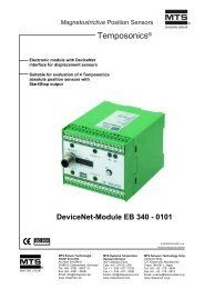
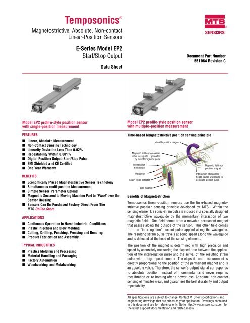
<strong>Model</strong> <strong>EP2</strong> profile-style position sensor<br />
with single-position measurement<br />
FEaTuRES<br />
Linear, absolute Measurement<br />
Non-Contact Sensing Technology<br />
Linearity Deviation Less Than 0.02%<br />
Repeatability Within 0.001%<br />
<strong>Digital</strong> Position <strong>Output</strong>: <strong>Start</strong>/<strong>Stop</strong> <strong>Pulse</strong><br />
EMI Shielded and CE Certified<br />
One Year Warranty<br />
E-<strong>Series</strong> <strong>Model</strong> <strong>EP2</strong><br />
<strong>Start</strong>/<strong>Stop</strong> <strong>Output</strong><br />
Data Sheet<br />
BENEFITS<br />
Economically Priced Magnetostrictive <strong>Sensor</strong> Technology<br />
Simultaneous multi-position Measurement<br />
Simple <strong>Sensor</strong> Parameter upload<br />
Magnet is Secured to Moving Machine Part to ‘Float’ over the<br />
<strong>Sensor</strong> Housing<br />
<strong>Sensor</strong>s Can Be Purchased Factory Direct From The<br />
MTS Online Store<br />
aPPLICaTIONS<br />
Continuous Operation in Harsh Industrial Conditions<br />
Plastic Injection and Blow Molding<br />
Cutting, Drilling, Punching, Pressing and Bending<br />
Product Fabrication and assembly<br />
TYPICaL INDuSTRIES<br />
Plastics Molding and Processing<br />
Material Handling and Packaging<br />
Factory automation<br />
Woodworking and Metalworking<br />
<strong>Model</strong> <strong>EP2</strong> profile-style position sensor<br />
with multiple-position measurement<br />
SENSORS<br />
Document Part Number<br />
551064 Revision C<br />
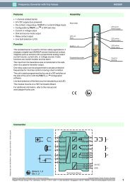
Time-based Magnetostrictive position sensing principle<br />
Magnetic field encompasses<br />
entire waveguide - generated<br />
by the interrogation pulse<br />
Interrogation<br />
Return wire<br />
Waveguide<br />
Strain-<strong>Pulse</strong> detector<br />
Bias magnet<br />
Movable position magnet<br />
Magnetic field from<br />
position magnet<br />
Interaction of magnetic<br />
fields causes waveguide to<br />
generate a strain pulse<br />
Benefits of Magnetostriction<br />
Temposonics linear-position sensors use the time-based magnetostrictive<br />
position sensing principle developed by MTS. Within the<br />
sensing element, a sonic-strain pulse is induced in a specially designed<br />
magnetostrictive waveguide by the momentary interaction of two<br />
magnetic fields. One field comes from a movable permanent magnet<br />
that passes along the outside of the sensor. The other field comes<br />
from an “interrogation” current pulse applied along the waveguide.<br />
The resulting strain pulse travels at sonic speed along the waveguide<br />
and is detected at the head of the sensing element.<br />
The position of the magnet is determined with high precision and<br />
speed by accurately measuring the elapsed time between the application<br />
of the interrogation pulse and the arrival of the resulting strain<br />
pulse with a high-speed counter. The elapsed time measurement is<br />
directly proportional to the position of the permanent magnet and is<br />
an absolute value. Therefore, the sensor's output signal corresponds<br />
to absolute position, instead of incremental, and never requires<br />
recalibration or re-homing after a power loss. Absolute, non-contact<br />
sensing eliminates wear, and guarantees the best durability and output<br />
repeatability.<br />
All specifications are subject to change. Contact MTS for specifications and<br />
engineering drawings that are critical to your application. Drawings contained<br />
in this document are for reference only. Go to http://www.mtssensors.com for<br />
the latest support documentation and related media.<br />
®
E-<strong>Series</strong> <strong>Model</strong> <strong>EP2</strong> <strong>Sensor</strong>, <strong>Start</strong>/<strong>Stop</strong> <strong>Output</strong><br />
Product Overview and Specifications<br />
Product overview<br />
MTS <strong>Sensor</strong>s continues to establish new performance standards<br />
for low-cost, fully-industrial, durable position sensors using the<br />
widely preferred magnetostrictive technology. This principle for<br />
accurate and non-contact measurement of linear-position sensing<br />
was developed 30 years ago by MTS and is used with<br />
outstanding success in a large variety of industrial applications.<br />
Product specifications<br />
Parameters Specifications<br />
OuTPuT<br />
Measured output Position; single or multi-position<br />
variables:<br />
measurements<br />
Resolution: 0.1, 0.01and 0.005 mm<br />
(controller dependent)<br />
Linearity deviation: < ± 0.02% full stroke<br />
(minimum ± 60 µm)<br />
Repeatability: < ± 0.001% full stroke<br />
(minimum ± 2.5 µm)<br />
<strong>Output</strong>: <strong>Digital</strong>-pulse (start/stop):<br />
RS-422 differential signal<br />
Serial parameter upload available for:<br />
measuring range, offset, gradient and<br />
status.<br />
Position<br />
Measurement Stroke lengths:<br />
measurement: 4, 6, 9, 12, 15, 18, 21, 24, 30, 36, 42,<br />
48, 54 and 60 inches<br />
ELECTRONICS<br />
Operating<br />
voltage:<br />
Contact factory for custom stroke<br />
lengths<br />
update frequency:<br />
Controller dependent<br />
+24 Vdc nominal: -15% or +20%<br />
Polarity protection: up to -30 Vdc<br />
Overvoltage protection: up to 36 Vdc<br />
Current drain: <strong>Start</strong>/<strong>Stop</strong>, 50 - 100 mA<br />
(Stroke length dependent)<br />
Dielectric withstand voltage: 500 Vdc<br />
(DC ground to machine ground)<br />
E-<strong>Series</strong> <strong>Model</strong> <strong>EP2</strong> Temposonics ® Linear-Position <strong>Sensor</strong>s - <strong>Digital</strong> (<strong>Start</strong>/<strong>Stop</strong>) <strong>Output</strong><br />
Product Data Sheet, Document Part No.: 551064, Revision C 01/10, 10/11<br />
2<br />
E-<strong>Series</strong> <strong>Model</strong> <strong>EP2</strong> sensors with digital-pulse (start/stop) output,<br />
can be ordered from the MTS Online Store at<br />
http://www.mtssensorsstore.com<br />
Parameters Specifications<br />
ENVIRONMENTaL<br />
Operating<br />
Operating temperature:<br />
conditions:<br />
-40 °C (-40 °F) to 75 °C (167 °F)<br />
Relative humidity:<br />
90% no condensation<br />
EMC test: Emissions: IEC/EN 50081-1<br />
Immunity: IEC/EN 50082-2<br />
IEC/EN 61000-4-2/3/4/6, criterium A,<br />
CE qualified<br />
Shock rating: 50 g (single hit)/<br />
IEC standard 60068-2-27 (survivability)<br />
Vibration rating: 5 g/10 to 2000 Hz, IEC standard<br />
60068-2-6 (operational)<br />
Wiring<br />
Connection type: 6-pin DIN (M16) male D60 connector<br />
PROFILE STYLE SENSOR (MODEL <strong>EP2</strong>)<br />
Sealing: IP 67<br />
<strong>Sensor</strong> extrusion: Aluminum<br />
Mounting: Any orientation. Adjustable mounting<br />
feet.<br />
Magnet type: Block magnet with stamped metal<br />
carrier<br />
MTS <strong>Sensor</strong>s
<strong>Output</strong><br />
The Temposonics E-<strong>Series</strong> <strong>Model</strong> <strong>EP2</strong> digitalpulse<br />
(start/stop) output sensor requires a start<br />
signal from a controller or interface module<br />
to initiate the measurement cycle. The sensor<br />
generates a stop signal at the end of the<br />
measurement cycle that is used to stop the<br />
controller’s counter clock. The elapsed time<br />
between the <strong>Start</strong> and <strong>Stop</strong> signals is directly<br />
proportional to the magnet’s position along the<br />
active stroke length. The controller can calculate<br />
the absolute position of the magnet from the time<br />
value and the sensor’s unique gradient value<br />
(inverse of the speed for the sonic pulse traveling<br />
in the sensor’s waveguide). (see 'Figure 1’).<br />
Communication and programmability<br />
SENSOR PaRaMETER uPLOaD FEaTuRE<br />
For applications using smart sensor interfaces, the E-<strong>Series</strong> <strong>Model</strong><br />
<strong>EP2</strong> with digital-pulse output comes with the ability to perform<br />
sensor parameter uploads. This feature replaces the manual task<br />
of entering sensor data saving time and preventing possible entry<br />
errors during start-up, or for system maintenance.<br />
The upload feature supports the following sensor parameters:<br />
• Measuring range<br />
• Offset<br />
• Gradient (Inverse speed of sensing pulse)<br />
• Status<br />
MTS <strong>Sensor</strong>s<br />
3<br />
E-<strong>Series</strong> <strong>Model</strong> <strong>EP2</strong> <strong>Sensor</strong>, <strong>Start</strong>/<strong>Stop</strong> <strong>Output</strong><br />
Programmability and <strong>Sensor</strong> Dimension References<br />
The sensor's specific parameters can be retrieved by the controller/<br />
interface module at any time, via the sensor’s start/stop signal lines.<br />
The sensor parameter upload feature requires a customer supplied<br />
RS-422 interface. The data format is serial, 4800 Baud, 8-bit data<br />
length. Please contact the factory for additional parameter upload<br />
protocol details.<br />
Muti-position measurement<br />
<strong>Model</strong> <strong>EP2</strong> profile-style sensor start/stop output dimension references<br />
<strong>Model</strong> <strong>EP2</strong>, profile-style sensor with Block, Style L Magnet<br />
Drawing is for reference only, contact applications engineering for tolerance specific information.<br />
6 pin DIN<br />
connector<br />
58 mm<br />
(2.3 in.)<br />
Beginning of stroke<br />
(Null) position<br />
11 mm (0.43 in.)<br />
Null<br />
72.5 mm<br />
(2.85 in.)<br />
<strong>Start</strong>/stop signal<br />
from controller or<br />
interface module<br />
Stroke length<br />
Mounting plate<br />
Block magnet, Style L<br />
14 mm (0.55 in.)<br />
14.5 mm<br />
(0.57 in.)<br />
<strong>Start</strong>/<strong>Stop</strong><br />
+ <strong>Start</strong><br />
- <strong>Start</strong><br />
The <strong>Model</strong> <strong>EP2</strong> digital-pulse output sensor provides multi-position<br />
measurements when used with more than one position magnet, and<br />
an appropriate controller/interface module. The minimum allowed<br />
distance between magnets is 3.0 in. (76 mm) to maintain proper<br />
sensor output. The total number of magnets is limited by the <strong>EP2</strong><br />
stroke length, and the interface module/controller that is used.<br />
Mounting feet<br />
<strong>Start</strong> <strong>Pulse</strong><br />
<strong>Start</strong> pulse `re�ection´<br />
Time between ‘<strong>Start</strong>’ and ‘<strong>Stop</strong>’ pulses<br />
are proportional to magnet position<br />
End of stroke<br />
(Span) position<br />
Dead zone<br />
72.5 mm<br />
(2.85 in.)<br />
<strong>Stop</strong> pulse<br />
<strong>Output</strong> signals<br />
from sensor<br />
25 mm<br />
(0.98 in.)<br />
Figure 2. E-<strong>Series</strong> <strong>Model</strong> <strong>EP2</strong> Profile-style sensor dimension reference (Shown with male 6-pin DIN and D60 integral connection type option)<br />
+ <strong>Stop</strong><br />
- <strong>Stop</strong><br />
Figure 1. <strong>Stop</strong>/start output signals (RS-422 differential pairs)<br />
Input signals<br />
to sensor<br />
E-<strong>Series</strong> <strong>Model</strong> <strong>EP2</strong> Temposonics ® Linear-Position <strong>Sensor</strong>s - <strong>Digital</strong> (<strong>Start</strong>/<strong>Stop</strong>) <strong>Output</strong><br />
Product Data Sheet, Document Part No.: 551064, Revision C 01/10, 10/11
E-<strong>Series</strong> <strong>Model</strong> <strong>EP2</strong> <strong>Sensor</strong>, <strong>Start</strong>/<strong>Stop</strong> <strong>Output</strong><br />
Magnet and Mounting References<br />
Standard magnet (<strong>Model</strong> <strong>EP2</strong>)<br />
One Block magnet included with <strong>Model</strong> <strong>EP2</strong> sensor<br />
The Style L ‘block’ magnet (part no.: 252887) mounts on the moving machine part and travels just above the sensor’s extrusion. The<br />
magnet can be mounted using ferrous metal screws on a mounting plate (customer supplied) or flat surface of the machine's moving<br />
part. The mounting plate or machine part can not extend beyond 11 mm (0.43 in.) from the top of the magnet, unless it is made of non-ferrous<br />
material. The magnet should be installed in a perpendicular orientation relative to the top surface of the sensor extrusion (see ‘Figure 2’).<br />
Optimal performance is achieved when this orientation remains consistent throughout the full measurement stroke range.<br />
BLOCK MaGNET, STYLE L (One Magnet included with each <strong>Model</strong> <strong>EP2</strong> sensor) (Drawing dimensions are for reference only)<br />
Magnet and mounted magnet dimensions Description Part number<br />
<strong>Sensor</strong> mounting<br />
MODEL <strong>EP2</strong> SENSOR MOuNTING<br />
11 mm<br />
(0.43 in.)<br />
2 mm<br />
(0.08 in.)<br />
radius<br />
19.5 mm<br />
(0.77 in.)<br />
31 mm<br />
(1.22 in.)<br />
4.5 mm (0.18 in.)<br />
6 mm (0.24 in.)<br />
20 mm (0.79 in.)<br />
E-<strong>Series</strong> <strong>Model</strong> <strong>EP2</strong> Temposonics ® Linear-Position <strong>Sensor</strong>s - <strong>Digital</strong> (<strong>Start</strong>/<strong>Stop</strong>) <strong>Output</strong><br />
Product Data Sheet, Document Part No.: 551064, Revision C 01/10, 10/11 4<br />
13.5 mm<br />
(0.53 in.)<br />
Block magnet, Style L<br />
For <strong>Model</strong> <strong>EP2</strong> profile-style<br />
sensor<br />
252887<br />
Temposonics model <strong>EP2</strong> profile-style sensors are mounted onto a flat straight surface of the machine with moveable mounting feet. A pair<br />
(2) mounting feet are provided with each sensor. Two additional mounting feet (part no. 400802) are included for measurement<br />
stroke lengths greater than 48 inches. Mounting feet slide into side grooves and should be evenly distributed along the sensor<br />
extrusion to best secure the sensor for each particular application.<br />
Notes:<br />
1. Additional mounting feet can be ordered separately.<br />
2. MTS recommends using 10-32 cap screws (customer supplied) at a maximum torque of 44 in. lbs. when fastening mounting feet.<br />
Profile-Style sensor mounting and installation reference Mounting method Part number<br />
Mounting foot and screws<br />
4 Holes<br />
5.3 mm<br />
(0.21 in.) dia.<br />
2 mm<br />
(0.08 in.)<br />
(Width = 14.5 mm (0.57 in.)<br />
Max gap<br />
3 mm ( ± 2 mm)<br />
(0.12 ± .08 in.)<br />
28 mm<br />
(1.1 in.)<br />
50 mm<br />
(1.97 in.)<br />
68 mm<br />
(2.68 in.)<br />
Block magnet<br />
9 mm<br />
(0.36 in.)<br />
9 mm<br />
(0.36 in.)<br />
Mounting plate<br />
(customer supplied)<br />
Mounting feet, standard (304 SS)<br />
Profile-style sensor mounting for<br />
sensor model <strong>EP2</strong><br />
Mounting feet and screws<br />
Profile-style sensor foot installation<br />
Secure mounting feet with customer<br />
supplied 10-32 Cap screws.<br />
(recommended )<br />
Block magnet, Style L mounting<br />
Magnet installs on a mounting plate<br />
(customer supplied) or flat surface of<br />
the machine's moving part.<br />
400802<br />
Mounting<br />
feet ,<br />
part number<br />
400802<br />
Block magnet,<br />
style L part<br />
number<br />
252887<br />
MTS <strong>Sensor</strong>s
<strong>Model</strong> <strong>EP2</strong> connections and wiring<br />
SENSOR INTEGRaL CONNECTOR (D60 MaLE) PINOuT/<br />
WIRE COLOR CODE (FOR ExTENSION CaBLE OPTION)<br />
The E-<strong>Series</strong> <strong>Model</strong> <strong>EP2</strong> sensor connects directly to a controller,<br />
or interface module via male, 6-pin integral connector and extension<br />
cable option.<br />
Wiring color and signal functions for the extension cable option<br />
are described in ‘Table 1’.<br />
MTS <strong>Sensor</strong>s<br />
5 4<br />
6 3<br />
1 2<br />
Integral D6 connector (male) as viewed<br />
from the end of the sensor<br />
Pin no. Wire color<br />
Signal/Function<br />
<strong>Digital</strong>-pulse outputs<br />
1 Gray (-) <strong>Stop</strong><br />
2 Pink (+) <strong>Stop</strong><br />
3 Yellow (+) <strong>Start</strong><br />
4 Green (-) <strong>Start</strong><br />
5 Red or Brown +24 Vdc (-15% / +20%)<br />
6 White DC Ground (0 Vdc)<br />
Table 1. <strong>EP2</strong> digital-pulse (start/stop) sensor extension cable<br />
wiring diagram<br />
5<br />
E-<strong>Series</strong> <strong>Model</strong> <strong>EP2</strong> <strong>Sensor</strong>, <strong>Start</strong>/<strong>Stop</strong> <strong>Output</strong><br />
Wiring, Connections and Cable Connector Options<br />
attention:<br />
The <strong>EP2</strong> sensor’s aluminum housing has an anodic coating<br />
which prevents the sensor's mounting feet (part no. 400802)<br />
from providing the appropriate grounding. A grounding lug (see<br />
‘Figure 3’) is provided near the connector end of the sensor for<br />
a convenient connection to earth ground.<br />
The appropriate grounding of the cable shield is required at the<br />
controller end.<br />
Grounding lug<br />
D6 Integral<br />
connector<br />
Figure 3. <strong>EP2</strong> <strong>Sensor</strong> grounding lug location<br />
Cable connector Options (field installable) 6-pin DIN (D60) female (Drawing dimensions are for reference only)<br />
Mounting<br />
foot<br />
Connector and connector dimensions Description Part number<br />
18 mm<br />
(0.7 in.) dia.<br />
18 mm<br />
(0.7 in.) dia.<br />
54 mm<br />
(2.1 in.)<br />
37 mm<br />
(1.5 in)<br />
54 mm<br />
(2.1 in.)<br />
Cable Connector, Female, Straight Exit<br />
(Field installable)<br />
6-Pin DIN (D60)<br />
Mates with standard male (M16) integral<br />
connector<br />
Cable Connector, Female, 90° Exit<br />
(Field installable)<br />
6-Pin DIN (D60)<br />
Mates with standard male (M16) integral<br />
connector<br />
560700<br />
560778<br />
E-<strong>Series</strong> <strong>Model</strong> <strong>EP2</strong> Temposonics ® Linear-Position <strong>Sensor</strong>s - <strong>Digital</strong> (<strong>Start</strong>/<strong>Stop</strong>) <strong>Output</strong><br />
Product Data Sheet, Document Part No.: 551064, Revision C 01/10, 10/11
E-<strong>Series</strong> <strong>Model</strong> <strong>EP2</strong> <strong>Sensor</strong>, <strong>Start</strong>/<strong>Stop</strong> <strong>Output</strong><br />
Extension Cable Options, Ordering Information<br />
ExTENSION CaBLE WITH CONNECTORS FOR D6 (D60) CONNECTION TYPES<br />
Extension Cable and Connector Description Connection type<br />
E-<strong>Series</strong> <strong>Model</strong> <strong>EP2</strong> Temposonics ® Linear-Position <strong>Sensor</strong>s - <strong>Digital</strong> (<strong>Start</strong>/<strong>Stop</strong>) <strong>Output</strong><br />
Product Data Sheet, Document Part No.: 551064, Revision C 01/10, 10/11<br />
Female Connector, Straight Exit<br />
with Standard PVC Jacket Cable<br />
(Assembly Includes D6 Connector, Part No.:<br />
560700 and Cable, Part No.:530026)<br />
Female Connector, 90° Exit<br />
with Standard PVC Jacket Cable<br />
(Assembly Includes D6 Connector, Part No.:<br />
560778 and Cable, Part No.:530026)<br />
Female Connector, Straight Exit<br />
with Black Polyurethane Jacket Cable (for<br />
higher resistance to moisture, oil and cold<br />
temperatures)<br />
(Assembly Includes D6 Connector, Part No.:<br />
560700 and Cable, Part No.:530052)<br />
Female Connector, 90° Exit<br />
with Black Polyurethane Jacket Cable (for<br />
higher resistance to moisture, oil and cold<br />
temperatures)<br />
(Assembly Includes D6 Connector, Part No.:<br />
560778 and Cable, Part No.:530052)<br />
Ordering Information - Extension Cable with Connector for D6 (D60) Connection Types<br />
SENSOR CONNECTION TYPES = D 1 - 2<br />
D6 =<br />
Female connector, straight exit (part no. 560700), and PVC jacket cable (part no. 530026)<br />
Da = Female connector, 90° exit (part no. 560778), and PVC jacket cable (part no. 530026)<br />
DJ = Female connector, straight exit (part no. 560700), and black polyurethane jacket cable (part no. 530052)<br />
DK = Female connector, 90° exit (part no. 560778), and black polyurethane jacket cable (part no. 530052)<br />
CaBLE LENGTHS = 3 - 5<br />
For standard length cables up to 100 ft<br />
005 = 5 ft.<br />
015 = 15 ft.<br />
025 = 25 ft.<br />
050 = 50 ft.<br />
100 = 100 ft.<br />
For custom length cables over 100 ft.<br />
— — — = Cable length (maximum cable length is dependent on the output selected; consult MTS Applications Engineering)<br />
CaBLE TERMINaTION = 6 - 8<br />
P0 = Pigtail cable without connector (2 digit code)<br />
D6M = D6 male connector (straight exit). Only available with the D6 option above.<br />
D6F = D6 female connector (straight exit). Only available with the D6 option above.<br />
DaF = D6 female connector (90° exit). Only available with the DA option above.<br />
6<br />
D<br />
D6<br />
DA<br />
DJ<br />
DK<br />
1 2 3 4 5 6 7 8<br />
MTS <strong>Sensor</strong>s
MTS <strong>Sensor</strong>s<br />
E-<strong>Series</strong> <strong>Model</strong> <strong>EP2</strong> <strong>Sensor</strong>, <strong>Start</strong>/<strong>Stop</strong> <strong>Output</strong><br />
Ordering Information<br />
Use the order matrix below to configure your <strong>Model</strong> <strong>EP2</strong> digital-pulse (start/stop) sensor order number. Contact the factory for custom<br />
sensor orders.<br />
For your convenience, the E-<strong>Series</strong> <strong>Model</strong> <strong>EP2</strong> sensor with digital-pulse (start/stop) output can be purchased from the MTS Online Store at:<br />
http://www.mtssensorsstore.com<br />
SENSOR MODEL = E P 2 D 1 - 4<br />
E-<strong>Series</strong> model <strong>EP2</strong> sensor with digital-pulse (start/stop) output<br />
E P 2 D -<br />
1 2 3 4 5 6 7<br />
— — — = MEaSuRING STROKE LENGTH IN INCHES = 5 - 7<br />
(Contact factory for custom stroke lengths)<br />
004 = 4 inch stroke length 024 = 24 inch stroke length<br />
006 = 6 inch stroke length 030 = 30 inch stroke length<br />
009 = 9 inch stroke length 036 = 36 inch stroke length<br />
012 = 12 inch stroke length 042 = 42 inch stroke length<br />
015 = 15 inch stroke length 048 = 48 inch stroke length<br />
018 = 18 inch stroke length 054 = 54 inch stroke length<br />
021 = 21 inch stroke length 060 = 60 inch stroke length<br />
7<br />
E-<strong>Series</strong> <strong>Model</strong> <strong>EP2</strong> Temposonics ® Linear-Position <strong>Sensor</strong>s - <strong>Digital</strong> (<strong>Start</strong>/<strong>Stop</strong>) <strong>Output</strong><br />
Product Data Sheet, Document Part No.: 551064, Revision C 01/10, 10/11
SENSORS<br />
®<br />
MTS Systems Corporation<br />
<strong>Sensor</strong>s Division<br />
3001 Sheldon Drive<br />
Cary, North Carolina<br />
27513, USA<br />
Tel.: +1-800-633-7609<br />
Fax: +1-919-677-2343<br />
+1-800-498-4442<br />
e-mail: sensorsinfo@mts.com<br />
http://www.mtssensors.com<br />
MTS and Temposonics are registered trademarks of MTS Systems Corporation.<br />
All other trademarks are the property of their respective owners.<br />
Printed in USA. Copyright © 2011 MTS Systems Corporation. All Rights Reserved in all media.<br />
MTS <strong>Sensor</strong> Technologie<br />
GmbH & Co. KG<br />
Auf dem Schüffel 9<br />
D - 58513 Lüdenscheid, Germany<br />
Tel.: +49-2351-9587-0<br />
Fax: +49-2351-56491<br />
e-mail: info@mtssensor.de<br />
http://www.mtssensor.de<br />
Document Part Number: 551064, Revision C 01/10, 10/11<br />
MTS <strong>Sensor</strong>s Technology<br />
Corporation<br />
737 Aihara-cho, Machida-shi<br />
Tokyo 194-0211, Japan<br />
Tel.: +81-42-775-3838<br />
Fax: +81-42-775-5516<br />
e-mail: info@mtssensor.co.jp<br />
http://www.mtssensor.co.jp