Pressure Transmitter cerabar M PMP 46 cerabar M PMP 48
Pressure Transmitter cerabar M PMP 46 cerabar M PMP 48
Pressure Transmitter cerabar M PMP 46 cerabar M PMP 48

You also want an ePaper? Increase the reach of your titles
YUMPU automatically turns print PDFs into web optimized ePapers that Google loves.
Technical<br />
Information<br />
TI 322P/00/en<br />
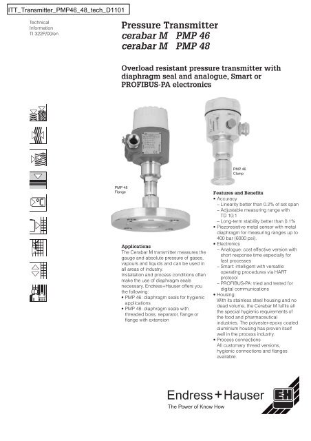
<strong>Pressure</strong> <strong>Transmitter</strong><br />
<strong>cerabar</strong> M <strong>PMP</strong> <strong>46</strong><br />
<strong>cerabar</strong> M <strong>PMP</strong> <strong>48</strong><br />
Overload resistant pressure transmitter with<br />
diaphragm seal and analogue, Smart or<br />
PROFIBUS-PA electronics<br />
<strong>PMP</strong> <strong>48</strong><br />
Flange<br />
Applications<br />
The Cerabar M transmitter measures the<br />
gauge and absolute pressure of gases,<br />
vapours and liquids and can be used in<br />
all areas of industry.<br />
Installation and process conditions often<br />
make the use of diaphragm seals<br />
necessary. Endress+Hauser offers you<br />
the following:<br />
• <strong>PMP</strong> <strong>46</strong>: diaphragm seals for hygienic<br />
applications<br />
• <strong>PMP</strong> <strong>48</strong>: diaphragm seals with<br />
threaded boss, separator, flange or<br />
flange with extension<br />
+<br />
Endress<br />
The Power of Know How<br />
<strong>PMP</strong> <strong>46</strong><br />
Clamp<br />
Features and Benefits<br />
• Accuracy<br />
− Linearity better than 0.2% of set span<br />
− Adjustable measuring range with<br />
TD 10:1<br />
− Long-term stability better than 0.1%<br />
• Piezoresistive metal sensor with metal<br />
diaphragm for measuring ranges up to<br />
400 bar (6000 psi).<br />
• Electronics<br />
− Analogue: cost effective version with<br />
short response time especially for<br />
fast processes<br />
− Smart: intelligent with versatile<br />
operating procedures via HART<br />
protocol<br />
− PROFIBUS-PA: tried and tested for<br />
digital communications<br />
• Housing<br />
With its stainless steel housing and no<br />
dead volume, the Cerabar M fulfils all<br />
the special hygienic requirements of<br />
the food and pharmaceutical<br />
industries. The polyester-epoxy coated<br />
aluminium housing has proven itself<br />
well in the process industry.<br />
• Process connections<br />
All customary thread versions,<br />
hygienic connections and flanges<br />
available.<br />
Hauser
Construction Diaphragm<br />
seal<br />
Hygienic<br />
applications<br />
Diaphragm<br />
seal<br />
Pipe<br />
diaphragm<br />
seal<br />
Threaded boss Diaphragm<br />
seal<br />
Threaded boss<br />
with separator<br />
Diaphragm<br />
seal<br />
Flange Diaphragm<br />
seal<br />
Flange with<br />
extension<br />
Diaphragm<br />
seal<br />
Connection Page/Version Standard Nominal width <strong>Pressure</strong><br />
range<br />
Groove nut Page 21 DIN 11851 DN 32,<br />
DN 40,<br />
DN 50<br />
Clamping<br />
bracket<br />
Page 23 SMS 1½", 2"<br />
Page 23 RJT 1½", 2"<br />
Page 23 ISS 1½", 2"<br />
Page 24 Varivent Type N<br />
Page 22 Clamp 1½", 2", 3"<br />
Flange Page 24 DRD D = 65 mm<br />
Thread<br />
adapter<br />
Clamping<br />
bracket<br />
Page 21 DIN 11851 DN 25,<br />
DN 40,<br />
DN 50<br />
Page 22 Clamp ¾", 1", 1½", 2"<br />
G Page 27 DIN ISO<br />
228/1<br />
NPT Page 27 ANSI<br />
B1.20.1<br />
G 1<br />
G 1½<br />
G 2<br />
1 NPT<br />
1½ NPT<br />
2 NPT<br />
max. 40 bar<br />
(600 psi)<br />
max. 400 bar<br />
(6000 psi)<br />
G Page 28 EN 837 G ½ max. 160 bar<br />
(2300 psi)<br />
NPT Page 28 ANSI<br />
B1.20.1<br />
DIN<br />
flange<br />
ANSI<br />
flange<br />
DIN<br />
flange<br />
ANSI<br />
flange<br />
½ NPT<br />
Page 29 DIN 2501 DN 25<br />
DN 50<br />
DN 80<br />
Page 30 ANSI B.16.5 1", 2", 3", 4"<br />
Page 29 DIN 2501 DN 50<br />
DN 80<br />
Page 30 ANSI B.16.5 2", 3", 4"<br />
2<br />
max. 400 bar<br />
(6000 psi)<br />
Instrument type<br />
<strong>PMP</strong> <strong>46</strong><br />
<strong>PMP</strong> <strong>48</strong>
Instrument Configuration of Cerabar M with Stainless Steel Housing<br />
display<br />
holder for<br />
display<br />
process connection<br />
<strong>PMP</strong> <strong>46</strong><br />
e.g. with dairy<br />
thread connection<br />
raised cover<br />
with sight glass<br />
for display<br />
low cover<br />
electronic insert<br />
housing<br />
process connection<br />
<strong>PMP</strong> <strong>48</strong><br />
e.g. flange<br />
3<br />
process connection<br />
<strong>PMP</strong> <strong>48</strong><br />
e.g. with G 2 A thread<br />
Housings<br />
The stainless steel housing of Cerabar M<br />
is especially remarkable due to its<br />
chemical resistance and hygienic<br />
properties. Having no dead volume and<br />
being condensation-tight with a surface<br />
roughness of Ra ≤ 0,8 μm, it is easy to<br />
clean and thereby ideal for the food and<br />
pharmaceutical industry.<br />
The aluminium housing has proven its<br />
ruggedness and has become a<br />
standard in many industries such as<br />
chemicals, papermaking, power<br />
generation, water and wastewater<br />
treatment.<br />
• Ingress protection<br />
− IP 65 with Harting plug (Han7D),<br />
− IP 66/Nema 4X as standard or<br />
− IP 68/Nema 6P with 5 m (16.4 ft)<br />
assembled cable with pressure<br />
compensation or plug M 12x1.<br />
This version is recommended for<br />
very moist applications (e.g. wet<br />
vessel walls or pipes).<br />
• Optional connection with<br />
− cable gland M 20x1.5 or<br />
− cable entry ½ NPT or G ½,<br />
− Harting plug (Han7D) or<br />
plug M 12x1 or<br />
− with assembled cable<br />
• A raised cover with sight glass is<br />
provided when using a display. A low<br />
cover is available for versions without<br />
a local display.<br />
Electronic Inserts<br />
Cerabar M has three electronics versions<br />
• Analogue: 4…20 mA<br />
Operation directly at the measuring<br />
point with one potentiometer each for<br />
lower range-value and upper<br />
range-value and a three-step range<br />
switch as well as an on/off switch for<br />
damping.<br />
• Smart: 4…20 mA with HART protocol<br />
Operation:<br />
− at the measuring point via two push<br />
buttons for lower range-value and<br />
upper range-value as well as an<br />
on/off switch for damping, or<br />
− via the Universal HART Communicator<br />
DXR 275 handheld terminal at any<br />
point along the 4…20 mA line, or<br />
− via PC e.g. with the Endress+Hauser<br />
Commuwin II operating program.<br />
• PROFIBUS-PA:<br />
Operation:<br />
– Using a PC with an operating<br />
program, e.g. Commuwin II from<br />
Endress+Hauser, or<br />
– using two keys for lower range-value<br />
and upper range-value.
Instrument Configuration of Cerabar M with Aluminium Housing<br />
display<br />
holder for<br />
display<br />
process connection<br />
<strong>PMP</strong> <strong>46</strong><br />
e.g. with dairy<br />
thread connection<br />
raised cover<br />
with sight glass<br />
for display<br />
low cover<br />
electronic insert<br />
housing<br />
process connection<br />
<strong>PMP</strong> <strong>48</strong><br />
e.g. flange<br />
process connection<br />
<strong>PMP</strong> <strong>48</strong><br />
e.g. with G 2 A thread<br />
4<br />
Displays<br />
A display module can be used for<br />
showing measured values and for<br />
simplifying local operation. The display<br />
is plugged onto the electronic insert<br />
using a holder.<br />
• Analogue display for Cerabar M with<br />
analogue electronics: The analogue<br />
display gives the current pressure<br />
value related to the measuring range<br />
in the form of a bar graph.<br />
• Digital display for Cerabar M with<br />
Smart electronics: The digital display<br />
gives the pressure in the form of a<br />
four-digit number. The appropriate<br />
current value from 4…20 mA is shown<br />
as a bar graph underneath.<br />
• Digital display for Cerabar M with<br />
PROFIBUS-PA electronics:<br />
The digital display gives the pressure<br />
in the form of a four-digit number. The<br />
bar graph depicts the current pressure<br />
value related to the measuring range.<br />
Process Connections<br />
• Process connections are available<br />
with all common threads,<br />
flush-mounted hygienic connections<br />
and flanges (see summary, page 2).<br />
• Chemical resistance can be<br />
guaranteed by selecting suitable<br />
materials for the process connection.<br />
This applies especially to the metal<br />
separating diaphragm of the<br />
diaphragm seal in contact with the<br />
medium.<br />
• The diaphragm is welded to every<br />
diaphragm seal with no dead volume.
Measuring System<br />
Complete measuring<br />
system Cerabar M<br />
above:<br />
with PROFIBUS-PA<br />
electronics<br />
below:<br />
with Smart electronics or<br />
with analogue electronics<br />
System Components<br />
The complete measuring system<br />
consists of:<br />
• Cerabar M pressure transmitter with<br />
− analogue output 4…20 mA and<br />
− supply voltage, e.g. with the<br />
RN 221N transmitter power supply<br />
unit from Endress+Hauser<br />
Supply voltage: 11.5…45 V DC<br />
Cerabar M<br />
Cerabar M<br />
5<br />
PROFIBUS-PA<br />
or<br />
• Cerabar M pressure transmitter with<br />
− 4…20 mA signal output and HART<br />
communication signal and<br />
− supply voltage, e.g. RN 221N<br />
transmitter power supply unit from<br />
Endress+Hauser<br />
Supply voltage: 11.5…45 V DC<br />
or Ex ia: 11.5…30 V DC<br />
or<br />
• Cerabar M pressure transmitter with<br />
− PROFIBUS-PA digital communication<br />
signal and<br />
− connection via segment coupler to a<br />
PLC or PC using e.g. the<br />
Endress+Hauser Commuwin II<br />
operating program<br />
Supply voltage: 9…32 V DC<br />
or Ex ia: 9…24 V DC<br />
PROFIBUS-DP<br />
ENDRESS + HAUSER<br />
via segment coupler<br />
connection to<br />
PLC or PC<br />
4…20 mA<br />
Supply voltage<br />
(e.g. with RN 221N):<br />
11.5…45 V DC<br />
for Ex ia (Smart electronics only):<br />
11.5…30 V DC
Operating Principle<br />
➀ Diaphragm of<br />
diaphragm seal<br />
➁ Copper ring<br />
➂ Diaphragm seal filling<br />
fluid<br />
➃ Metallic<br />
separation diaphragm<br />
➄ Channel with<br />
filling fluid<br />
➅ Polysilicone<br />
measuring element<br />
Piezoresistive Sensor with<br />
Diaphragm Seal<br />
The process pressure acting on the<br />
diaphragm of the diaphragm seal is<br />
transmitted to the metallic separating<br />
diaphragm of the sensor by the filling<br />
fluid of the diaphragm seal. The<br />
separating diaphragm is deflected and<br />
the fluid transmits the pressure to a<br />
resistance bridge. The bridge output<br />
voltage, which is proportional to<br />
pressure, is then measured and<br />
evaluated.<br />
Advantages:<br />
• For process pressures up to 400 bar<br />
(6000 psi)<br />
• Excellent long-term stability<br />
• Guaranteed resistance to overload up<br />
to 4-times nominal pressure<br />
(max. 600 bar/9000 psi)<br />
6<br />
5<br />
4<br />
3<br />
2<br />
1<br />
process pressure<br />
6<br />
6<br />
5<br />
4<br />
3<br />
2<br />
1<br />
process pressure
Operation<br />
Analogue Electronics<br />
For the Cerabar M with analogue<br />
electronics lower range-value (Zero)<br />
and upper range-value (Span) are<br />
directly calibrated at the measuring<br />
point via two potentiometers. The<br />
required lower and upper range-values<br />
must be applied as reference pressure.<br />
• For coarse calibration of the<br />
measuring span, a spread between<br />
TD 1:1 and TD 10:1 can be selected<br />
using DIP switches.<br />
• A 2 s damping of the measured value<br />
can be activated using a DIP switch.<br />
• The analogue display shows the<br />
pressure on a bar graph as a ratio to<br />
the measuring range.<br />
• Over- or under-run of the signal can<br />
be indicated by a flashing of the bar<br />
graph.<br />
Smart Electronics<br />
A Cerabar M with Smart electronics can<br />
be calibrated with or without reference<br />
pressure.<br />
– When calibrating with reference<br />
pressure, the pressure for lower<br />
range-value and upper range-value<br />
must be entered and confirmed by<br />
pressing the Zero or Span key twice.<br />
Press these keys once to display saved<br />
values for lower range-value and upper<br />
range-value.<br />
– If you calibrate without reference<br />
pressure, enter the measuring points<br />
using a handheld terminal or using an<br />
operating program.<br />
• A damping of 2 s can be set directly<br />
on the instrument. A damping value of<br />
0...40 s can be selected using<br />
communication.<br />
• The digital display shows the pressure<br />
as a four-character number. The<br />
appropriate 4…20 mA current is<br />
shown as a bar graph underneath.<br />
• Error codes on the digital display and<br />
in Commuwin II simplify error<br />
diagnosis.<br />
Three electronics versions are available<br />
for operating the Cerabar M.<br />
• The analogue electronics is the<br />
simplest and most cost-effective<br />
method to operate the Cerabar M.<br />
• Smart electronics opens up a wide<br />
range of operating and calibration<br />
routines. It can then be operated<br />
either by means of a handheld<br />
terminal or an operating program (e.g.<br />
Endress+Hauser Commuwin II).<br />
Analogue display<br />
(optional)<br />
Digital display<br />
(optional)<br />
0,753<br />
7<br />
1 2<br />
+ –<br />
1 2<br />
+ –<br />
3<br />
• The PROFIBUS-PA electronics provide<br />
direct connection to the PROFIBUS-PA<br />
field bus. The PROFIBUS-PA can be<br />
easily set up and many values are<br />
retrievable from the control room.<br />
1 2 3 τ<br />
Display<br />
Zero Span<br />
fine coarse τ<br />
1 2 3<br />
off<br />
on<br />
Zero Span<br />
1 23 τ<br />
fine coarse<br />
Potentiometer for<br />
calibrating the<br />
lower range-value<br />
Potentiometer and switches<br />
for calibrating the upper range-value<br />
Coarse adjustment<br />
for upper range-value<br />
Damping Zero Span<br />
3 on off<br />
Display<br />
TD 1:1<br />
TD 3:1<br />
TD 6:1<br />
TD 10:1<br />
Switch position “on”<br />
Damping = 2 s activated<br />
Operating elements<br />
1 23<br />
1 23<br />
1 23<br />
TD: turn down<br />
1<br />
2 3<br />
τ<br />
τ<br />
off<br />
on<br />
τ<br />
τ<br />
Damping switch<br />
Operating elements<br />
Keys for<br />
calibrating the<br />
lower rangevalue<br />
and upper<br />
range-value<br />
1x<br />
Damping<br />
on<br />
Zero<br />
off<br />
on<br />
off<br />
on<br />
off<br />
on<br />
off<br />
on<br />
Switch position "on"<br />
Damping = 2 s activated<br />
2x<br />
1x<br />
2x<br />
off<br />
Span<br />
Lower rangevalue:<br />
Display<br />
Registration<br />
Upper rangevalue:<br />
Display<br />
Registration
Cerabar M<br />
operation with Smart<br />
electronics using a<br />
handheld terminal<br />
PROFIBUS-PA Electronics<br />
A Cerabar M with PROFIBUS-PA<br />
electronics has the following operating<br />
options.<br />
• You can set a damping of between 0<br />
and 40 s using communication.<br />
• You can set instrument bus address<br />
direct in the instrument using the<br />
address switch.<br />
Digital display<br />
(optional)<br />
0,753<br />
Smart Electronics Operation Using a<br />
Handheld Terminal<br />
Using the Universal HART<br />
Communicator DXR 275 handheld<br />
terminal, you can set the Cerabar M,<br />
make checks and use additional<br />
functions such as "Damping" and<br />
"Calibration without reference pressure"<br />
all along the 4...20 mA line.<br />
Cerabar M<br />
8<br />
EX EX<br />
• The digital display gives the pressure<br />
as a four-digit number. The bar graph<br />
depicts the current pressure value<br />
related to the measuring range. The<br />
measuring range can be set either on<br />
site using the Zero and Span keys or<br />
remotely using an operating program,<br />
such as Commuwin II.<br />
• Error codes on the digital display and<br />
in Commuwin II simplify error<br />
diagnosis.<br />
Zero Span<br />
1 2 3<br />
on address<br />
off<br />
Display<br />
R<br />
I O<br />
I O<br />
Operating elements<br />
SW<br />
1 2 4 8 16 32 64 HW Value<br />
1 2 3 4 5 6 7 8<br />
DIP switches to set<br />
bus address<br />
Keys for<br />
calibrating the<br />
lower rangevalue<br />
and upper<br />
range-value<br />
1x<br />
minimum line resistance<br />
250 Ω<br />
4...20 mA<br />
2x<br />
1x<br />
2x<br />
Universal HART Comunicator<br />
DXR 275<br />
ON<br />
OFF<br />
Switch No.<br />
Zero Span<br />
Lower rangevalue:<br />
Display<br />
Registration<br />
Upper rangevalue:<br />
Display<br />
Registration<br />
*<br />
* Use an<br />
intrinsically<br />
safe supply<br />
voltage for Ex i<br />
(e.g. RN 221 N)
Cerabar M<br />
operation with Smart<br />
electronics using PC<br />
Cerabar M<br />
operation with<br />
PROFIBUS-PA<br />
electronics<br />
Smart Electronics Operation Using<br />
PC<br />
The Commubox FXA 191 connects<br />
4…20 mA Smart transmitters that have a<br />
HART protocol to the RS 232 C serial<br />
interface of a personal computer. This<br />
enables the transmitter to be remotely<br />
operated with the Endress+Hauser<br />
Commuwin II operating program.<br />
You can connect the Commubox<br />
FXA 191 at any point along the<br />
4…20 mA line. It is also suited for<br />
connection to intrinsically-safe signal<br />
circuits.<br />
Commubox<br />
FXA 191<br />
PC with<br />
operating program<br />
e.g. Commuwin II<br />
Cerabar M<br />
Connecting to PROFIBUS-PA<br />
PROFIBUS-PA is an open fieldbus<br />
standard to enable serveral sensors and<br />
actuators, including those in<br />
explosion-hazardous areas, to be<br />
connected to bus line. With<br />
PROFIBUS-PA, two-wire looped<br />
instruments can be supplied by the<br />
sensor with power and digital process<br />
information.<br />
9<br />
Cerabar M<br />
pressure transmitters<br />
PC with<br />
operating program<br />
e.g. Commuwin II<br />
PROFIBUS-DP<br />
supply voltage<br />
4…20 mA<br />
+<br />
minimum line<br />
resistance<br />
250 Ω<br />
The number of instruments operated by<br />
one bus segment is:<br />
• up to 10 for Ex ia applications<br />
• up to 32 for all further applications<br />
(e.g. non-Ex, EEx nA)<br />
Fieldbus with<br />
PROFIBUS-PA<br />
ENDRESS + HAUSER<br />
PLC<br />
segment coupler
Installation<br />
Mounting Instructions<br />
• The protective cap of the diaphragm<br />
seal should only be removed just<br />
before mounting.<br />
• The diaphragm seal and the pressure<br />
sensor together form a closed,<br />
oil-filled, calibrated system. The<br />
following rules should be observed:<br />
− The filling hole is sealed and not to<br />
be opened.<br />
− When mounting the Cerabar M, it<br />
should only be turned by the nut of<br />
the diaphragm seal and not by the<br />
hex nut of the Cerabar M.<br />
Cleaning<br />
The diaphragm of the diaphragm seal<br />
must not be pressed in or cleaned with<br />
pointed or hard objects.<br />
Mounting<br />
To prevent moisture from entering, the<br />
cable entry should preferably hang<br />
downwards or to the side.<br />
vertical<br />
mounting<br />
Mounting with Temperature Spacer<br />
Endress+Hauser recommends the use<br />
of a temperature spacer when extreme<br />
media temperatures (from approx.<br />
150°C/302°F) continually cause the<br />
ambient temperature to exceed the<br />
permissible limit of +85°C (+185°F).<br />
Cerabar M with<br />
temperature spacer<br />
10<br />
cable points<br />
downwards<br />
Shifting of the Zero Point due to<br />
Position<br />
The Cerabar M is calibrated based on<br />
the limit point method according to<br />
DIN 16086.<br />
Depending on the orientation of the<br />
instrument, there may be a slight shift in<br />
the measured value. Diaphragm seals<br />
also shift the zero point depending on<br />
the orientation of the instrument.<br />
• neutral calibration position<br />
• max. positive zero point shift<br />
• max. negative zero point shift<br />
This zero point shift due to position can<br />
be corrected (refer to zero point<br />
increase and decrease, page 16).<br />
The max. effect of position for all<br />
diaphragm seals is given in the tables<br />
on page 21 onwards. These values are<br />
for silicone oil. For other oils available,<br />
the shift in zero point due to position<br />
varies according to the density of the oil<br />
(see page 12).<br />
Information on the maximum installation<br />
heightisgivenonpage21onwards<br />
100 mm *<br />
(3.94 in)<br />
* Additional zero point shift<br />
caused by the hydrostatic<br />
pressure of the water column<br />
in the temperature spacer:<br />
10 mbar (0.15 psi)
Installation<br />
(Continuation)<br />
Dimensions<br />
• 1 mm = 0.039 in<br />
1 in = 25.4 mm<br />
Values in brackets apply<br />
to instruments with<br />
raised cover.<br />
Values in italics apply to<br />
instruments with an<br />
aluminium housing.<br />
Alldimensionsareinmm.<br />
Mounting with Capillary Tubing<br />
To protect from high temperatures (max.<br />
350°C/+662°F media temperature),<br />
moisture, vibration, or where the<br />
mounting point is not easily accessible,<br />
the housing of the Cerabar M can be<br />
mounted with a capillary tubing away<br />
from the measuring point.<br />
A bracket for mounting on a wall and<br />
pipe is available for this:<br />
• Material: 1.4301 (AISI 304)<br />
• Order No.: 52001402<br />
(It can also be selected as an<br />
accessory in the Product Structure.)<br />
81<br />
70<br />
60.3<br />
11<br />
Mounting point remote<br />
from the measuring point<br />
119.5<br />
184.5<br />
187.6<br />
26 99 (119)<br />
108 (122)<br />
Measuring point:<br />
• very moist<br />
• hot<br />
• strongly vibrating<br />
• difficult to access<br />
108 (122)<br />
99 (119)<br />
26<br />
3<br />
102.5<br />
167.5<br />
170.7
Design Planning for<br />
the Diaphragm Seal<br />
Filling fluid<br />
of<br />
diaphragm seal<br />
Silicone oil<br />
(AK 100)<br />
Hightemperature<br />
oil<br />
(paraffin)<br />
Fluorolube FS-5 1)<br />
Code Permissible<br />
temperature of<br />
medium at<br />
0.05 bar ≤ pabs ≤ 1 bar<br />
(0.73 psi ≤ pabs ≤ 14.5 psi)<br />
A, J –40…+180°C<br />
(–40…+356°F)<br />
G,<br />
H, K<br />
–10…+200°C<br />
(+14…+392°F)<br />
N –40…+80°C<br />
(–40…+176°F)<br />
Diaphragm Seal Filling Fluid<br />
The temperature and pressure of the<br />
process are of critical importance when<br />
selecting the filling fluid for the<br />
diaphragm seal.<br />
➀, ➁<br />
The suitability of the fluid to meet the<br />
requirements of the medium must also<br />
be considered. For foodstuffs<br />
applications, only physiologically safe<br />
fluids such as vegetable oil or silicone<br />
oil (AK 100) may be used in the<br />
diaphragm seal.<br />
➄<br />
Smallest Recommended Measuring<br />
Span and Diaphragm Diameter<br />
The effects of temperature cause the<br />
diaphragm seal to expand. This in turn<br />
gives rise to an additional temperature<br />
effect on the zero point. When selecting<br />
the diaphragm seal the following points<br />
are to be observed:<br />
• The nominal diameter of the<br />
diaphragm seal determines the width<br />
of the diaphragm.<br />
• Temperature effects vary inversely<br />
with the width of the diaphragm<br />
diameter.<br />
The largest possible width of diaphragm<br />
should be chosen for small measuring<br />
spans and/or capillaries so that<br />
temperature effects remain within the<br />
nominal range of the application.<br />
Permissible<br />
temperature of<br />
medium at<br />
pabs ≥ 1 bar<br />
(pabs ≥ 14.5 psi)<br />
–40… +250°C<br />
(–40…+<strong>48</strong>2°F)<br />
–10… +350°C<br />
(+14…+662°F)<br />
–40…+175°C<br />
(–40…+347°F)<br />
Glycerine E — +15…+200°C<br />
(+59…+392°F)<br />
Vegetable oil<br />
(Neobee M20)<br />
Maximum<br />
height<br />
difference<br />
at pabs ≥ 1 bar<br />
(pabs ≥ 14.5 psi)<br />
max. 7 m<br />
(max. 23 ft)<br />
max. 7 m<br />
(max. 23 ft)<br />
Minimum<br />
permissible<br />
pressure<br />
at +20°C<br />
(+68°F)<br />
10 mbarabs<br />
(0.15 psi)<br />
10 mbarabs<br />
(0.15 psi)<br />
Guidelines for Mounting Capillary<br />
Tubes<br />
The transmitter should generally be<br />
mounted below the tapping point. A<br />
maximum height difference between the<br />
tapping point and transmitter should not<br />
be exceeded. This will otherwise result<br />
in a break in the column of fluid in the<br />
capillary and damage the diaphragm<br />
seal.<br />
➂<br />
• Minimum bending radius of capillary<br />
tubing: 100 mm (3.94 in).<br />
• In the case of applications in vacuum,<br />
the instrument should be mounted<br />
below the pressure tapping point.<br />
Temperature Effects<br />
The temperature coefficients of the<br />
diaphragm seals as stated in the<br />
technical data and dimensions (page 21<br />
onwards) apply to silicone oil<br />
(calibrating temperature +20°C/+68°F)<br />
and are determined by the process and<br />
ambient temperatures.<br />
For other fluids, the TK value is to be<br />
multiplied by the TK correction factor.<br />
➃<br />
For instruments with capillary tubing, the<br />
total temperature coefficient TK can be<br />
calculated by adding the TK of the<br />
Cerabar M to that of the diaphragm<br />
seal, together with the TK of the capillary<br />
tubing.<br />
The TK of the capillary tubing is<br />
determined by the ambient temperature:<br />
TK per meter for silicone oil:<br />
0.5 mbar/10 K.<br />
➀ ➁ ➂ ➃ ➄<br />
D, F –10…+120°C<br />
(+14…+392°F)<br />
–10…+200°C<br />
(+14…+392°F)<br />
1) Observe operating limits for oxygen service for non-metallic materials.<br />
max. 7 m<br />
(max. 23 ft)<br />
max. 4 m<br />
(max. 13.1 ft)<br />
max. 7 m<br />
(max. 23 ft)<br />
12<br />
10 mbarabs<br />
(0.15 psi)<br />
10 mbarabs<br />
(0.15 psi)<br />
10 mbarabs<br />
(0.15 psi)<br />
Density<br />
[g/cm 3 ]<br />
TK - Remarks<br />
Correction<br />
factor<br />
0,96 1 standard, foodstuffs<br />
applications<br />
0.81 0.72<br />
1.87 0.91 inert oil e.g. for oxygen<br />
or chlorine<br />
1.26 0.64 foodstuffs applications<br />
0.94 1.05 FDA No.:<br />
21CFR172.856
Electrical Connection<br />
* For analogue<br />
electronics versions with<br />
certificate ATEX II 1/3 D<br />
(non Ex supply voltage)<br />
the instrument must<br />
always be protected by a<br />
50 mA (slow-blow) fuse.<br />
Load diagram for<br />
analogue and Smart<br />
electronics<br />
Wiring Analogue and Smart<br />
Electronics<br />
The two-wire cable is connected to<br />
screw terminals on the electronic insert.<br />
• Supply voltage: 11.5…45 V DC;<br />
additional for Smart electronics<br />
Ex ia: 11.5…30 V DC<br />
• Cable:<br />
− Analogue: two-wire instrumentation<br />
cable<br />
− Smart: screened, twisted-pairs<br />
− max. wire cross-section: 2.5 mm 2<br />
(solid conductor)<br />
Electrical connection analogue electronics<br />
T50mA *<br />
R/Ω<br />
1522<br />
1000<br />
840<br />
500<br />
1 2<br />
+ –<br />
1 2<br />
+<br />
–<br />
3<br />
3<br />
Zero Span<br />
fine coarse<br />
+<br />
–<br />
1 2 3 τ<br />
Display<br />
Test 4…20 mA<br />
internal ground terminal<br />
0<br />
11.5 20 30 45 U/V<br />
Standard<br />
EEx ia IIC T6<br />
13<br />
• Internal protection circuits against<br />
reverse polarity, HF interference and<br />
overvoltage peaks.<br />
• Test signal:<br />
The output current can be measured<br />
using the terminal plugs for this<br />
purpose on the electronic insert<br />
without interrupting the process<br />
measurement.<br />
• Always connect the screening or<br />
ground cable (if present) to the<br />
internal ground terminal of the<br />
housing, not to terminal 3.<br />
Electrical connection Smart electronics<br />
1 2<br />
+ –<br />
1 2<br />
+<br />
–<br />
3<br />
Damping Zero Span<br />
3 on off<br />
+<br />
–<br />
Test 4…20 mA<br />
Display<br />
internal ground terminal
Wiring PROFIBUS-PA<br />
The digital communication signal is<br />
transmitted to the bus using a two-wire<br />
connecting cable. The bus cable also<br />
carries the supply voltage.<br />
• Supply voltage: 9…32 V DC<br />
Ex ia: 9…24 V DC<br />
• Bus cable:<br />
Use a twisted, screened two-wire<br />
cable. The following specifications<br />
must be observed when using the<br />
FISCO model (explosion protection):<br />
− Loop resistance (DC):<br />
15…150 Ω/km<br />
− Inductance: 0.4…1 mH/km<br />
− Capacitance: 80…200 nF/km<br />
Connection: M12 Plug<br />
(PROFIBUS-PA)<br />
Endress+Hauser also provides a<br />
Cerabar M with a M12 plug. This version<br />
can be easily connected to the<br />
PROFIBUS network using a<br />
preterminated cable.<br />
Versions:<br />
• PM ❏ 4❏ – ❏ L1 ❏❏ ❏ P ❏❏❏❏(❏)<br />
• PM ❏ 4❏ – ❏ L1 ❏❏ ❏ R ❏❏❏❏(❏)<br />
• PM ❏ 4❏ – ❏ L2 ❏❏ ❏ P ❏❏❏❏(❏)<br />
• PM ❏ 4❏ – ❏ L2 ❏❏ ❏ R ❏❏❏❏(❏)<br />
View onto pins, plug on instrument<br />
PA–<br />
(blue)<br />
1 2 3<br />
bn bu bk<br />
1<br />
+<br />
–<br />
not<br />
connected<br />
Cerabar M<br />
2 3 M12<br />
PROFIBUS-PA<br />
screen<br />
screen<br />
(black)<br />
PA+<br />
(brown)<br />
• Always connect the screening or<br />
ground cable (if present) to the<br />
internal ground terminal of the<br />
housing, not to terminal 3.<br />
Infomation on the structure and<br />
grounding of the network are given in<br />
Operating Instructions BA 198F<br />
»PROFIBUS-PA: Guidelines for planning<br />
and comissioning« and the<br />
PROFIBUS-PA specification EN 50170<br />
(DIN 19245).<br />
Connection M12 Plug<br />
For hygienic applications or humid<br />
operating areas, Endress+Hauser also<br />
offers a Cerabar M with a M12 plug with<br />
IP 68 ingress protection. A socket for<br />
user-specific connection to this housing<br />
connector is available from<br />
Endress+Hauser, order no. 52006263.<br />
Versions:<br />
• <strong>PMP</strong> 4❏ – ❏ L1 ❏❏ ❏ H ❏❏❏❏(❏)<br />
• <strong>PMP</strong> 4❏ – ❏ L1 ❏❏ ❏ I ❏❏❏❏(❏)<br />
• <strong>PMP</strong> 4❏ – ❏ L2 ❏❏ ❏ H ❏❏❏❏(❏)<br />
• <strong>PMP</strong> 4❏ – ❏ L2 ❏❏ ❏ I ❏❏❏❏(❏)<br />
• <strong>PMP</strong> 4❏ – ❏ L1 ❏❏ ❏ A ❏❏❏❏(❏)<br />
• <strong>PMP</strong> 4❏ – ❏ L1 ❏❏ ❏ C ❏❏❏❏(❏)<br />
• <strong>PMP</strong> 4❏ – ❏ L2 ❏❏ ❏ A ❏❏❏❏(❏)<br />
• <strong>PMP</strong> 4❏ – ❏ L2 ❏❏ ❏ C ❏❏❏❏(❏)<br />
View onto pins, plug on instrument<br />
–<br />
(black)<br />
1 2 3<br />
rd bk gn<br />
1<br />
+<br />
–<br />
not<br />
connected<br />
Cerabar M<br />
2 3 M12<br />
screen<br />
+<br />
(red)<br />
14<br />
screen<br />
(green)<br />
Electrical connection PROFIBUS-PA electronics<br />
1 2 3<br />
+ –<br />
1 2 3<br />
+ –<br />
on<br />
off<br />
address<br />
Zero Span<br />
Display<br />
internal ground terminal<br />
Connection Harting Plug<br />
For applications in power stations, there<br />
is a Cerabar M with a Han7D Harting<br />
plug:<br />
Versions:<br />
• PM ❏ 4❏ – ❏ H1 ❏❏ ❏ ❏ ❏ ❏❏ ❏ (❏)<br />
• PM ❏ 4❏ – ❏ H2 ❏❏ ❏ ❏ ❏ ❏❏ ❏ (❏)<br />
Plug on instrument<br />
1 2 3<br />
bu bn<br />
gnye<br />
1<br />
+<br />
2 3<br />
–<br />
7<br />
6<br />
1<br />
5<br />
4<br />
screen<br />
+<br />
(blue)<br />
8<br />
2<br />
3<br />
Cerabar M<br />
Han7D<br />
PE connection<br />
(green yellow)<br />
–<br />
(brown)
Technical Data<br />
General Information Manufacturer Endress+Hauser<br />
Instrument <strong>Pressure</strong> transmitter<br />
Designation Cerabar M <strong>PMP</strong> <strong>46</strong>, <strong>PMP</strong> <strong>48</strong><br />
Technical documentation<br />
TI 322P/00/en<br />
Version<br />
11.01<br />
Technical data<br />
according to DIN 19259<br />
Application Measurement of absolute and gauge pressure in gases, vapours, liquids and dusts<br />
Operation and System Design Measuring principle<br />
Piezoresistive sensor with diaphragm seal The process pressure acting on the diaphragm of the<br />
diaphragm seal is transmitted to the metal separating<br />
diaphragm of the sensor by a filling fluid. The separating<br />
diaphragm is deflected and the resulting pressure<br />
proportional change in the output voltage of the resistance<br />
bridge is then measured and evaluated.<br />
Working volume: smaller than 1 mm 2 (0.039 in 2 )<br />
Measuring system<br />
with analogue electronics<br />
(see page 7)<br />
with Smart electronics<br />
(see page 7)<br />
with PROFIBUS-PA electronics<br />
(see page 8)<br />
Cerabar M and supply voltage<br />
Calibration via potentiometers for lower range-value and upper<br />
range-value, optional analogue display<br />
Cerabar M and supply voltage:<br />
– two keys on the instrument<br />
Universal HART Communicator DXR 275<br />
– PC with operating program e.g. Commuwin II via<br />
Commubox FXA 191<br />
Optional digital display.<br />
Connection via segment coupler to PLC or PC with an<br />
operating program e.g. Commuwin II.<br />
Optional digital display.<br />
Construction Stainless steel or aluminium housing,<br />
all common diaphragm seal versions<br />
see "Product Structure" and "Dimensions"<br />
Signal transmission Analogue<br />
Smart<br />
PROFIBUS-PA<br />
Input Measured variables Absolute or gauge pressure<br />
Measuring ranges<br />
<strong>PMP</strong> <strong>46</strong> (max. 40 bar), <strong>PMP</strong> <strong>48</strong><br />
Type of<br />
pressure<br />
Measurement<br />
limits<br />
Min. span Overload Type of<br />
pressure<br />
– 4…20 mA, 2-wire<br />
– 4…20 mA with superposed HART communication signal,<br />
2-wire<br />
– digital communication signal, 2-wire<br />
Measurement<br />
limits<br />
Min. Span Overload<br />
bar bar bar bar bar bar bar<br />
gauge 0…1 0.1 4 absolute 0…1 0.1 4<br />
gauge 0…4 0.4 16 absolute 0…4 0.4 16<br />
gauge 0…10 1 40 absolute 0…10 1 40<br />
gauge 0…40* 4 160 absolute 0…40 4 160<br />
gauge 0…100* 10 400 absolute 0…100 10 400<br />
gauge 0…400* 40 600 absolute 0…400 40 600<br />
gauge –1…+1 0.2 4 * Absolute pressure sensors<br />
gauge –1…+4 0.5 16<br />
gauge –1…+10 1.1 40<br />
The stated overload applies to the sensor. Please also note the maximum permissible overloads for the diaphragm<br />
seals.<br />
15
Input (Continuation) Resistance to low pressures (vacuum resistance) to 10 mbarabsolute (0.15 psia)<br />
Adjusting the span (turn down) to TD 10:1 (see also this page figure 2)<br />
Zero point increase and Analogue – ±10% within extended measurement limits<br />
decrease Smart – any within extended measurement limits<br />
PROFIBUS-PA – any within extended measurement limits<br />
(see also this page figure 1)<br />
Output Analogue signal 4…20 mA (analogue electronics)<br />
Output signal 4…20 mA<br />
Signal on alarm Signal overrun (>20.5 mA) or underrun (
Process conditions Installation conditions<br />
Ambient conditions<br />
Any position<br />
Zero point shift due to position can be corrected,<br />
see page 16, " Zero point increase and decrease"<br />
Ambient temperature –40…+85°C (–40…+185°F)<br />
For instruments approved for use in hazardous areas, see<br />
Safety Instructions (XA…), Installation Drawing (CSA) or<br />
Control Drawing (FM).<br />
Ambient temperature range (temporary) –40…+100°C (–40…+212°F)<br />
Storage temperature –40…+85°C (–40…+185°F)<br />
Climatic class 4K4H to DIN EN 60721-3<br />
Protection – IP 65: Instruments with Harting plug Han7D<br />
– IP 66/Nema 4X: instruments with cable gland, cable entry<br />
or M 12 plug (in combination with gauge pressure sensor)<br />
– IP 68 (1m water over 24 h) or NEMA 6P (1.8 m water over<br />
30 min): instruments with assembled cable or M 12 plug<br />
(in combination with absolute pressure sensor)<br />
Electromagnetic compatibility Interference Emission to EN 61326, Electrical Equipment<br />
Class B, Interference immunity to EN 61326 Annex A<br />
(Industrial) and NAMUR Recommendation EMC (NE 21)<br />
Influence to EMC ≤0.5%<br />
Smart and PROFIBUS-PA electronics: Twisted, screened<br />
pairs must be used.<br />
Process conditions<br />
Process temperature Depending on maximum permissible temperature of filling<br />
liquid of diaphragm seal and diameter of diaphragm<br />
(see also page 12)<br />
For instruments approved for use in hazardous areas, see<br />
Safety Instructions (XA…), Installation Drawing (CSA) or<br />
Control Drawing (FM).<br />
Process pressure corresponds to permissible overload<br />
see table on page 15 Measuring ranges, Overload<br />
Mechanical Construction Design<br />
Housing Stainless steel (type F 15) with a surface roughness<br />
Ra ≤ 0.8 μm or aluminium (type F 18)<br />
Optional electrical connection via<br />
– M 20 x 1.5 cable gland<br />
– Cable entry G ½, ½ NPT,<br />
– Harting plug (Han7D) or M 12x1 plug<br />
– assembled cable with reference air feed<br />
Process connections<br />
Materials<br />
All common diaphragm seal versions, see "Product Structure"<br />
and "Dimensions"<br />
Housing – Stainless steel 1.4404 (AISI 316L) or<br />
– cast aluminium housing with protective polyester based<br />
powder coating<br />
Nameplate Stainless steel housing – Engraved on housing with laser<br />
Aluminium housing – 1.4301 (AISI 304)<br />
Process connections (in contact with the medium) 1.4435 (AISI 316L)<br />
Union nuts 1.4307 (AISI 304L)<br />
Process diaphragm <strong>PMP</strong> <strong>46</strong> – 1.4435 (AISI 316L)<br />
(in contact with the medium) <strong>PMP</strong> <strong>48</strong> – 1.4435 (AISI 316L), Hastelloy 2.<strong>48</strong>19 (C 276), tantalum,<br />
PTFE film 0.09 mm (0.0035 in) on 1.4435 (AISI 316L) (not<br />
for vacuum)<br />
PTFE film 0.25 mm (0.0098 in) on 1.4435 (AISI 316L) (not<br />
for vacuum)<br />
O-Ring for Stainless steel housing – Silicone<br />
cover sealing Aluminium housing – NBR<br />
Bracket for pipe and wall mounting 1.4301 (AISI 304)<br />
Filling fluid in diaphragm seals Silicone oil, vegetable oil (FDA listed), glycerine,<br />
high-temperature oil, Fluorolobe (see also page 12)<br />
17
Display and Operating Interface Display and Operation<br />
Display Analogue – Pluggable analogue display with bar graph<br />
(optional)<br />
(<strong>Pressure</strong> display related to set measuring range as bar<br />
graph with 30 segments)<br />
Smart and PROFIBUS-PA – Pluggable digital display and extra bar graph<br />
(<strong>Pressure</strong> display as four-digit number and also in relating<br />
to set measuring range as bar graph with 28 segments)<br />
Display resolution Analogue display – Bar graph: 1 segment equals 3.33% of the set measuring<br />
range<br />
Digital display – Digital display 0.1%<br />
bar graph: 1 segment equals 3.57% of the set measuring<br />
range<br />
Operation Analogue – Lower range-value and upper range-value calibration using<br />
two potentiometers and DIP switches on the instrument<br />
Smart – Lower range-value and upper range-value calibration using<br />
two keys on the instrument<br />
Communication Interfaces<br />
PROFIBUS-PA – Lower range-value and upper range-value calibration for<br />
the bar graph using two keys on the instrument<br />
For further setting options, refer to pages 7…9<br />
Handheld terminal HART protocol: Universal HART Communicator DXR 275,<br />
The HART Communicator can be connected anywhere along<br />
the 4…20 mA line,<br />
minimum line resistance: 250 Ω<br />
PC Connection via Commubox FXA 191 to a serial interface of a<br />
PC<br />
The commubox can be connected anywhere along the<br />
4…20 mA line.<br />
minimum line resistance: 250 Ω<br />
Operating e.g. via Commuwin II operating program.<br />
PROFIBUS-PA Connection via segment coupler connection to PLC or PC<br />
with an operating program e.g. Commuwin II<br />
Power Supply<br />
Analogue and Smart Electronics<br />
Supply voltage – 11.5…45 V DC<br />
– Ex ia: 11.5…30 V DC (Smart electronics only)<br />
Overvoltage category II to DIN EN 61010-1<br />
Ripple<br />
PROFIBUS-PA Electronics<br />
No effect for 4…20 mA signal up to ±5% residual ripple<br />
within permissible range<br />
With HART Communicator and Commubox:<br />
max. ripple (measured on 500 Ω) 47…125 Hz:<br />
UPP=200 mV<br />
max. noise (measured on 500 Ω) 500 Hz…10 kHz:<br />
Ueff=2.2 mV<br />
Supply voltage – 9…32 V DC<br />
– Ex ia: 9…24 V DC, see also Safety Instructions (XA…),<br />
Installation Drawing (CSA) or Control Drawing (FM).<br />
Current consumption 10 mA ± 1 mA<br />
Power up current Corresponds to table 4, IEC 61158-2<br />
Certificates and Approvals Ignition protection see "Product Structure, Certificates"<br />
CE Mark By attaching the CE Mark, Endress+Hauser confirms that<br />
the instrument fulfils all the requirements of the relevant EC<br />
directives.<br />
Order Code see "Product Structure"<br />
Supplementary Documentation Cerabar M System Information: SI 038P/00/en<br />
Cerabar M Technical Information: TI 321P/00/en<br />
Cerabar M with analogue electronics Operating Instructions: BA 200P/00/en<br />
Cerabar M with Smart electronics Operating Instructions: BA 201P/00/en<br />
Cerabar M PROFIBUS-PA Operating Instructions: BA 222P/00/en<br />
PROFIBUS-DP/PA, Guidelines for planning and comissioning: BA 198F/00/en<br />
ATEX II 1/2 G EEx ia IIC T4/T6 Safety Instructions: XA 039P/00<br />
ATEX II 1/2 G EEx ia IIC T4/T6, PROFIBUS-PA Safety Instructions: XA 096P/00<br />
ATEX II 2 G EEx ia IIC T4/T6 Safety Instructions: XA 130P/00<br />
ATEX II 2 G EEx ia IIC T4/T6, PROFIBUS-PA Safety Instructions: XA 149P/00<br />
ATEX II 3 G EEx nA II T5 Safety Instructions: XA 052P/00<br />
ATEX II 1/2 D EEx ia IIC T4/T6 Safety Instructions: XA 038P/00<br />
ATEX II 1/2 D EEx ia IIC T4/T6, PROFIBUS-PA Safety Instructions: XA 097P/00<br />
ATEX II 1/3 D Safety Instructions: XA 040P/00<br />
ATEX II 1/3 D PROFIBUS-PA Safety Instructions: XA 098P/00<br />
EMC guidelines Technical Information: TI 241F/00/en<br />
18
Product Structure<br />
<strong>PMP</strong> <strong>46</strong><br />
Cerabar M <strong>PMP</strong> <strong>46</strong><br />
Certificates<br />
R Standard<br />
G ATEX II 1/2 G, EEx ia IIC T6<br />
H ATEX II 2 G, EEx ia IIC T6<br />
N ATEX II 3 G, EEx nA II T5<br />
K ATEX II 1/2 D, EEx ia IIC T6<br />
L ATEX II 1/3 D (non-Ex power supply)<br />
C CSA General Purpose<br />
S CSA IS (suitable for Div. 2) Cl. I, II, III, Div. 1, Groups A…G<br />
T CSA, Cl. I, Div. 2, Groups A…D; Cl. II, III, Div. 1, Groups E…G<br />
P FM IS (non-incendive) Cl. I, II, III, Div. 1, Groups A…G<br />
M FM DIP, Cl. II, III, Div. 1, Groups E…G<br />
V TIIS Ex ia IIC T6<br />
Housing<br />
Stainless steel 1.4404 (AISI 316L) Aluminium<br />
E1 Cable gland M 20x1.5 E2 Cable gland M 20x1.5<br />
G1 Cable entry G ½ G2 Cable entry G ½<br />
C1 Cable entry ½ NPT C2 Cable entry ½ NPT<br />
H1 Harting plug (Han7D) H2 Harting plug (Han7D)<br />
L1 Plug M 12x1 L2 Plug M 12x1<br />
K1 5 m cable (with pressure compensation) K2 5 m cable (with pressure compensation)<br />
Metal Sensor: Nominal Value (Maximum Overload)<br />
Gauge pressure<br />
3H 0…1 bar (4 bar) 100 kPa (400 kPa) 15 psig (60 psig)<br />
3M 0…4 bar (16 bar) 400 kPa (1.6 MPa) 60 psig (240 psig)<br />
3P 0…10 bar (40 bar) 1 MPa (4 MPa) 150 psig (600 psig)<br />
3S 0…40 bar (160 bar) 4 MPa (16 MPa) 600 psig (2400 psig)<br />
Absolute pressure<br />
4H 0…1 bar (4 bar) 100 kPa (400 kPa) 15 psia (60 psig)<br />
4M 0…4 bar (16 bar) 400 kPa (1.6 MPa) 60 psia (240 psig)<br />
4P 0…10 bar (40 bar) 1 MPa (4 MPa) 150 psia (600 psig)<br />
4S 0…40 bar (160 bar) 4 MPa (16 MPa) 600 psia (2400 psig)<br />
Negative gauge pressure<br />
7H –1…+1 bar (4 bar) –100…100 kPa (400 kPa) –15…15 psig (60 psig)<br />
7M –1…+4 bar (16 bar) –100…400 kPa (1.6 MPa) –15…60 psig (240 psig)<br />
7P –1…+10 bar (40 bar) –0.1…1 MPa (4 MPa) –15…150 psig (600 psig)<br />
Calibration and Technical Units<br />
1 Calibrated nominal value mbar/bar<br />
2 Calibrated nominal value kPa/MPa<br />
3 Calibrated nominal value mm H2O/m H2O<br />
4<br />
5<br />
Calibrated nominal value inch H2O<br />
Calibrated nominal value kgf/cm2 6 Calibrated nominal value psi<br />
B Calibrated from … to … technical unit … (bar, kPa, psi …)<br />
9 Others<br />
Electronics, Display<br />
A Analogue 4…20 mA, without display C Analogue 4…20 mA, with analogue display<br />
H HART 4…20 mA, without display J HART 4…20 mA, with digital display<br />
P PROFIBUS-PA, without display<br />
Accessories/Certification<br />
R PROFIBUS-PA, with digital display<br />
1 None<br />
2 Bracket for pipe and wall mounting<br />
C 3.1.B Inspection certificate for all parts in contact with the medium made of 1.4435 (AISI 316L)<br />
9 Others<br />
Code for Process Connection See Page 20<br />
<strong>PMP</strong> <strong>46</strong> Product designation<br />
Filling Fluid in Diaphragm Seal and Coupling of Diaphragm Seal<br />
Notes on Code H, F, J: Capillary >1 with diaphragm seals from DN 50 or 2" only<br />
A Silicone oil, direct coupling<br />
D Vegetable oil (FDA listed), direct coupling<br />
E Glycerine, direct coupling<br />
G High-temperature oil, with temperature spacer 100 mm (3.94 in)<br />
K 1 m (3.28 ft) capillary tubing with high-temperature oil<br />
H …m capillary tubing with high-temperature oil<br />
F …m capillary tubing with vegetable oil<br />
J …m capillary tubing with silicone oil<br />
N Fluorolube, grease-free for oxygen service, direct coupling<br />
Y Others<br />
19
in combination with diaphragm seals:<br />
– Dairy DIN 11851,<br />
versions AG, AH and AL as well as<br />
PB, PH and PL<br />
– Varivent, version LL<br />
Note!<br />
To meet the requirements of the EHEDG,<br />
these instruments should be installed in<br />
accordance with Hygienic Equipment<br />
Design Criteria.<br />
Dimensions<br />
Housing<br />
Dimensions<br />
• 1 mm = 0.039 in<br />
1 in = 25.4 mm<br />
All dimensions are in mm.<br />
Housing<br />
• above: Stainless steel<br />
1.4404 (AISI 316L)<br />
below: Aluminium<br />
• optional cover raised<br />
(with display) or low<br />
Values in brackets apply<br />
to instruments with<br />
raised cover.<br />
Values in italics apply to<br />
instruments with an<br />
aluminium housing.<br />
Diaphragm and Pipe Seal for Hygienic Applications<br />
Material 1.4435 (AISI 316L)<br />
Diaphragm seal<br />
AG Dairy thread DIN 11851, DN 32, PN 40<br />
AH Dairy thread DIN 11851, DN 40, PN 40<br />
AL Dairy thread DIN 11851, DN 50, PN 40<br />
DG Clamp, 1½", PN 40<br />
DL Clamp, 2", PN 40<br />
DU Clamp, 3", PN 40<br />
EG SMS thread,1½", PN 40<br />
EL SMS thread, 2", PN 40<br />
FG RJT thread, 1½", PN 40<br />
FL RJT thread, 2", PN 40<br />
GG ISS thread, 1½", PN 40<br />
GL ISS thread, 2", PN 40<br />
KL DRD flange, D=65 mm<br />
LL Varivent, type N for pipes DN 40…125<br />
Pipe diaphragm seal<br />
PB Dairy thread DIN 11851, DN 25, PN 40<br />
PH Dairy thread DIN 11851, DN 40, PN 40<br />
PL Dairy thread DIN 11851, DN 50, PN 40<br />
SA Clamp, ¾", PN 40<br />
SB Clamp, 1", PN 40<br />
SG Clamp, 1½", PN 40<br />
SL Clamp, 2", PN 40<br />
YY Others<br />
Code for process connection<br />
125 (145 )<br />
135 (150)<br />
20<br />
97 74<br />
27 AF<br />
117 74<br />
27 AF
Dimensions<br />
<strong>PMP</strong> <strong>46</strong><br />
Conversion factors<br />
• 1 mm = 0.039 in<br />
1in=25.4mm<br />
• 1 kg = 2.2 lbs<br />
1 lbs = 0.45 kg<br />
• 1 bar = 14.5 psi<br />
1 psi = 0.069 bar<br />
Process connection<br />
• Wetted parts of<br />
diaphragm seal:<br />
1.4435 (AISI 316L)<br />
• Standard surface<br />
roughness of parts in<br />
contact with the<br />
medium Ra ≤ 0.8 μm.<br />
Reduced surface<br />
roughness on request.<br />
Diaphragm seal<br />
conical sleeve with groove nut, DIN 11851 (dairy thread)<br />
Instrument<br />
Diaphragm Seal<br />
Conical Sleeve with Groove Nut<br />
DIN 11851 (Dairy Thread)<br />
A<br />
m<br />
d M<br />
D<br />
G<br />
f<br />
Pipe Diaphragm Seal<br />
DIN 11851 (Dairy Thread)<br />
Code Pipe Conical sleeve Groove nut Diaphragm seal Stainless<br />
steel housing<br />
Nominal<br />
diameter<br />
Nominal pressure<br />
Diameter<br />
Sleeve height<br />
Thread<br />
Height<br />
Diaphragm<br />
diameter<br />
Temperature<br />
coefficient T<br />
K<br />
(for silicone oil,<br />
for other oils,<br />
seepage12)<br />
Recommended<br />
minimum<br />
measuring range<br />
A<br />
Max. effects of<br />
mounting position<br />
(see page 10)<br />
Height of<br />
Cerabar M<br />
L<br />
L 1<br />
Total weight<br />
D<br />
G<br />
d1 Aluminium<br />
housing<br />
DN PN D f G m d<br />
M<br />
Ambient Process max. A max. A<br />
mm bar mm mm mm mm mbar/10K mbar/10K bar mbar mm kg mm kg<br />
<strong>PMP</strong> <strong>46</strong> AG 32 40 50 10 Rd 58 x 1/6" 21 32 +3 +4 from 2.0 9 251.5 1.4 256.5 1.7<br />
<strong>PMP</strong> <strong>46</strong> AH 40 40 56 10 Rd 65 x 1/6" 21 38 +2 +4 from 0.4 9 250.5 1.4 255.5 1.7<br />
<strong>PMP</strong> <strong>46</strong> AL 50 40 68 11 Rd 78 x 1/6" 25 <strong>46</strong> +1 +2 from 0.1 8 245.5 1.6 250.5 1.9<br />
Pipe diaphragm seal DIN 11851 (dairy thread)<br />
Instrument<br />
Code Pipe Conical sleeve Diaphragm seal Stainless<br />
steel housing<br />
Nominal<br />
diameter<br />
Nominal pressure<br />
Diameter<br />
Diameter<br />
Thread<br />
Height<br />
Total length<br />
Temperature<br />
coefficient T<br />
K<br />
(for silicone oil,<br />
for other oils,<br />
seepage12)<br />
Recommended<br />
minimum<br />
measuring range<br />
Max. effects of<br />
mounting position<br />
(see page 10)<br />
Height of<br />
Cerabar M<br />
Total weight<br />
Height of<br />
Cerabar M<br />
Total weight<br />
Aluminium<br />
housing<br />
DN PN D d<br />
1<br />
G L L<br />
1<br />
Ambient Process max. A max. A<br />
mm bar mm mm mm mm mbar/10K mbar/10K bar mbar mm kg mm kg<br />
<strong>PMP</strong> <strong>46</strong> PB 25 40 26,2 58 Rd 52 x 1/6" 126 140 +4 +8 from 2.0 8 273.5 3.0 278.5 3.3<br />
<strong>PMP</strong> <strong>46</strong> PH 40 40 38 78 Rd 65 x 1/6" 126 140 +2 +4 from 0.4 10 283.5 3.4 292.5 3.7<br />
<strong>PMP</strong> <strong>46</strong> PL 50 40 50,7 88 Rd 78 x 1/6" 100 114 +1 +2 from 0.1 11 288.5 3.8 293.5 4.1<br />
21<br />
Height of<br />
Cerabar M<br />
Total weight
Dimensions<br />
<strong>PMP</strong> <strong>46</strong><br />
Diaphragm seal Clamp<br />
Instrument<br />
Conversion factors<br />
• 1 mm = 0.039 in<br />
1 in = 25.4 mm<br />
• 1 kg = 2.2 lbs<br />
1 lbs = 0.45 kg<br />
• 1 bar = 14.5 psi<br />
1 psi = 0.069 bar<br />
Process connection<br />
• Wetted parts of<br />
diaphragm seal:<br />
1.4435 (AISI 316L)<br />
• Standard surface<br />
roughness of parts in<br />
contact with the<br />
medium Ra ≤ 0.8 μm.<br />
Reduced surface<br />
roughness on request.<br />
Clamp Diaphragm Seal Clamp Pipe Diaphragm Seal<br />
A<br />
Code Clamp Diaphragm seal Stainless<br />
steel housing<br />
Nominal<br />
diameter<br />
Nominal pressure<br />
Diameter<br />
Diaphragm<br />
diameter<br />
d M<br />
d 3<br />
Temperature<br />
coefficient T<br />
K<br />
(for silicone oil,<br />
for other oils,<br />
seepage12)<br />
Recommended<br />
minimum<br />
measuring range<br />
A<br />
Max. effects of<br />
mounting position<br />
(see page 10)<br />
Height of<br />
Cerabar M<br />
L<br />
Total weight<br />
d1 d2 d3 Aluminium<br />
housing<br />
DN PN d3 dM Ambient Process max. A max. A<br />
ISO 2852 DIN 32676 Triclamp<br />
mm mm inch bar mm mm mbar/10K mbar/10K bar mbar mm kg mm kg<br />
<strong>PMP</strong> <strong>46</strong> DG 25/33.7/38 25/32/40 1½" 40 50.5 34 +3 +4 from 0.4 8 234.5 1.0 239.5 1.3<br />
<strong>PMP</strong> <strong>46</strong> DL 40/51 50 2" 40 64 45 +1 +2 from 0.1 9 242.5 1.2 247.5 1.5<br />
<strong>PMP</strong> <strong>46</strong> DU 70/76.1 65 3" 40 91 71,5 +1 +2 from 0.1 9 242.5 1.4 247.5 1.7<br />
Pipe diaphragm seal Clamp<br />
Instrument<br />
Code Pipe Clamp Diaphragm seal Stainless steel<br />
housing<br />
Nominal<br />
diameter<br />
Nominal pressure<br />
Diameter<br />
Diameter<br />
Diameter<br />
Installation length<br />
Temperature<br />
coefficient T<br />
K<br />
(for silicone oil,<br />
for other oils,<br />
seepage12)<br />
Recommended<br />
minimum<br />
measuring range<br />
Max. effects of<br />
mounting position<br />
(see page 10)<br />
Height of<br />
Cerabar M<br />
Total weight<br />
Height of<br />
Cerabar M<br />
Aluminium<br />
housing<br />
DN<br />
ISO 2852<br />
PN d1 d2 d3 L Ambient Process max. A max. A<br />
mm bar mm mm mm mm mbar/10K mbar/10K bar mbar mm kg mm kg<br />
<strong>PMP</strong> <strong>46</strong> SA 15 40 10.5 18 25 140 +7 +11 from 6.0 8 220 2.6 225 2.9<br />
<strong>PMP</strong> <strong>46</strong> SB 25 40 22.5 41.5 50.5 126 +4 +8 from 2.0 8 220 3.0 225 3.3<br />
<strong>PMP</strong> <strong>46</strong> SG 40 40 35.5 41.5 50.5 126 +2 +4 from 0.4 9 257 3.4 262 3.7<br />
<strong>PMP</strong> <strong>46</strong> SL 50 40 <strong>48</strong>.6 55 64 100 +1 +2 from 0.1 11 268 3.8 273 4.1<br />
22<br />
Height of<br />
Cerabar M<br />
Total weight<br />
Total weight
Dimensions<br />
<strong>PMP</strong> <strong>46</strong><br />
Conversion factors<br />
• 1 mm = 0.039 in<br />
1 in = 25.4 mm<br />
• 1 kg = 2.2 lbs<br />
1 lbs = 0.45 kg<br />
• 1 bar = 14.5 psi<br />
1 psi = 0.069 bar<br />
Process connection<br />
• Wetted parts of<br />
diaphragm seal:<br />
1.4435 (AISI 316L)<br />
• Standard surface<br />
roughness of parts in<br />
contact with the<br />
medium Ra ≤ 0.8 μm.<br />
Reduced surface<br />
roughness on request.<br />
Diaphragm seal SMS sleeve with groove nut<br />
Instrument<br />
SMS Sleeve with Groove Nut RJT Sleeve with Groove Nut<br />
A<br />
m<br />
d M<br />
G<br />
D<br />
f<br />
A<br />
d M<br />
G<br />
D<br />
ISS Sleeve with Groove Nut<br />
Code Pipe Conical sleeve Groove nut Diaphragm seal Stainless<br />
steel housing<br />
Nominal<br />
diameter<br />
Nominal pressure<br />
Diameter<br />
Sleeve height<br />
Thread<br />
Height<br />
Diaphragm<br />
diameter<br />
Temperature<br />
coefficient T<br />
K<br />
(for silicone oil,<br />
for other oils,<br />
seepage12)<br />
Recommended<br />
minimum<br />
measuring range<br />
A<br />
AF<br />
Max. effects of<br />
mounting position<br />
(see page 10)<br />
d M<br />
G<br />
D<br />
Height of<br />
Cerabar M<br />
Total weight<br />
f<br />
m<br />
f<br />
m<br />
Aluminium<br />
housing<br />
DN PN D f G m d<br />
M<br />
Ambient Process max. A max. A<br />
bar mm mm mm mm mbar/10K mbar/10K bar mbar mm kg mm kg<br />
<strong>PMP</strong> <strong>46</strong> EG 1½" 40 74 4 Rd 60 - 1/6" 25 34 +4 +4 from 0.4 8 254.5 1.4 259.5 1.7<br />
<strong>PMP</strong> <strong>46</strong> EL 2" 40 84 4 Rd 70 - 1/6" 26 <strong>46</strong> +2 +2 from 0.1 9 259.5 1.6 264.5 1.9<br />
Diaphragm seal RJT sleeve with groove nut<br />
Instrument<br />
Code Pipe Conical sleeve Groove nut Diaphragm seal Stainless<br />
steel housing<br />
Nominal<br />
diameter<br />
Nominal pressure<br />
Diameter<br />
Sleeve height<br />
Thread<br />
Height<br />
Diaphragm<br />
diameter<br />
Temperature<br />
coefficient T<br />
K<br />
(for silicone oil,<br />
for other oils,<br />
seepage12)<br />
Recommended<br />
minimum<br />
measuring range<br />
Max. effects of<br />
mounting position<br />
(see page 10)<br />
Height of<br />
Cerabar M<br />
Total weight<br />
Height of<br />
Cerabar M<br />
Total weight<br />
Aluminium<br />
housing<br />
DN PN D f G m d<br />
M<br />
Ambient Process max. A max. A<br />
bar mm mm mm mm mbar/10K mbar/10K bar mbar mm kg mm kg<br />
<strong>PMP</strong> <strong>46</strong> FG 1½" 40 72 6.4 2 5/16" - 1/8" 21 28 +8 +8 from 0.4 8 257 1.6 262 1.9<br />
<strong>PMP</strong> <strong>46</strong> FL 2" 40 86 6.4 2 7/8" - 1/8" 22 38 +3 +4 from 0.1 9 258 1.7 263 2.0<br />
Diaphragm seal ISS sleeve with groove nut<br />
Instrument<br />
Code Pipe Conical sleeve Groove nut Diaphragm seal Stainl. steel<br />
housing<br />
Nominal<br />
diameter<br />
Nominal pressure<br />
Diameter<br />
Sleeve height<br />
Thread<br />
Height<br />
Across flats<br />
Diaphragm<br />
diameter<br />
Temperature<br />
coefficient T<br />
K<br />
(for silicone oil,<br />
for other oils,<br />
seepage12)<br />
Recommended<br />
minimum<br />
measuring range<br />
Max. effects of<br />
mounting position<br />
(see page 10)<br />
Height of<br />
Cerabar M<br />
Total weight<br />
Height of<br />
Cerabar M<br />
Total weight<br />
Aluminium<br />
housing<br />
DN PN D f G m AF d<br />
M<br />
Ambient Process max. A max. A<br />
bar mm mm mm mm mm mbar/10K mbar/10K bar mbar mm kg mm kg<br />
<strong>PMP</strong> <strong>46</strong> GG 1½" 40 62 AF 4 2" - 1/8" 30 62 34 +4 +4 from 0.4 8 267.5 1.4 272.5 1.7<br />
<strong>PMP</strong> <strong>46</strong> GL 2" 40 77 AF 4 2 1/2" - 1/8" 30 77 45 +2 +2 from 0.1 9 267.5 1.8 272.5 2.1<br />
23<br />
Height of<br />
Cerabar M<br />
Total weight
Dimensions<br />
<strong>PMP</strong> <strong>46</strong><br />
Conversion factors<br />
• 1 mm = 0.039 in<br />
1in=25.4mm<br />
• 1 kg = 2.2 lbs<br />
1 lbs = 0.45 kg<br />
• 1 bar = 14.5 psi<br />
1 psi = 0.069 bar<br />
Process connection<br />
• Wetted parts of<br />
diaphragm seal:<br />
1.4435 (AISI 316L)<br />
• Standard surface<br />
roughness of parts in<br />
contact with the<br />
medium Ra ≤ 0.8 μm.<br />
Reduced surface<br />
roughness on request.<br />
Diaphragm seal Varivent Type N and DRD<br />
Instrument<br />
Varivent DRD Flange<br />
A<br />
Code Neck/Flange Bolt holes Diaphragm seal Stainless<br />
steel housing<br />
Nominal pressure<br />
Extension length<br />
Extension<br />
diameter<br />
Internal diameter<br />
Diameter<br />
Number<br />
Diameter<br />
13<br />
16<br />
Pitch diameter<br />
M10<br />
Diaphragm<br />
diameter<br />
3<br />
dM D<br />
ø105<br />
ø66<br />
ø50<br />
ø125<br />
ø84<br />
Temperature<br />
coefficient T<br />
K<br />
(for silicone oil,<br />
for other oils,<br />
see page 12)<br />
15<br />
20<br />
45°<br />
Recommended<br />
minimum<br />
measuring range<br />
A<br />
seal<br />
l<br />
Max. effects of<br />
mounting position<br />
(see page 10)<br />
Height of<br />
Cerabar M<br />
dM d1 d2 k<br />
D<br />
Total weight<br />
Welding Flange<br />
Endress+Hauser offers a welding flange<br />
with PTFE flat packing for the<br />
flush-mounted installation of the DRD<br />
flange (version KL).<br />
Material: 1.4435 (AISI 316L)<br />
Order No.: 52002041<br />
only PTFE flat seal:<br />
Order No.: 91783-0000<br />
g 2<br />
Aluminium<br />
housing<br />
PN l d2 d1 D g2k d<br />
M<br />
Ambient Process max. A max. A<br />
bar mm mm mm mm mm mm mm mbar/10K mbar/10K bar mbar mm kg mm kg<br />
<strong>PMP</strong> <strong>46</strong> LL 40 – – – 68 – – – <strong>46</strong> +2 +2 from 0.1 11 235.5 1.3 252.5 1.6<br />
<strong>PMP</strong> <strong>46</strong> KL 40 17 65 50 105 4 10.5 84 <strong>46</strong> +2 +2 from 0.1 11 239.5 1.6 258.5 1.9<br />
24<br />
Height of<br />
Cerabar M<br />
Total weight
Product Structure<br />
<strong>PMP</strong> <strong>48</strong><br />
Cerabar M <strong>PMP</strong> <strong>48</strong><br />
Certificates<br />
R Standard<br />
G ATEX II 1/2 G, EEx ia IIC T6<br />
H ATEX II 2 G, EEx ia IIC T6<br />
N ATEX II 3 G, EEx nA II T5<br />
K ATEX II 1/2 D, EEx ia IIC T6<br />
L ATEX II 1/3 D (non-Ex power supply)<br />
C CSA General Purpose<br />
S CSA IS (suitable for Div. 2) Cl. I, II, III, Div. 1, Groups A…G<br />
T CSA Cl. I, Div. 2, Groups A…D, Cl. II, III, Div. 1, Groups E…G<br />
P FM IS (non-incendive) Cl. I, II, III, Div. 1, Groups A…G<br />
M FM DIP, Cl. II, III, Div. 1, Groups E…G<br />
V TIIS Ex ia IIC T6<br />
Housing<br />
Stainless steel 1.4404 (AISI 316L) Aluminium<br />
E1 Cable gland M 20x1.5 E2 Cable gland M 20x1.5<br />
G1 Cable entry G ½ G2 Cable entry G ½<br />
C1 Cable entry ½ NPT C2 Cable entry ½ NPT<br />
H1 Harting plug (Han7D) H2 Harting plug (Han7D)<br />
L1 Plug M 12x1 L2 Plug M 12x1<br />
K1 5 m cable (with pressure compensation) K2 5 m cable (with pressure compensation)<br />
Metal Sensor: Nominal Value (Maximum Overload)<br />
Gauge pressure<br />
3H 0…1 bar (4 bar) 100 kPa (400 kPa) 15 psig (60 psig)<br />
3M 0…4 bar (16 bar) 400 kPa (1.6 MPa) 60 psig (240 psig)<br />
3P 0…10 bar (40 bar) 1 MPa (4 MPa) 150 psig (600 psig)<br />
3S 0…40 bar (160 bar) 4 MPa (16 MPa) 600 psig (2400 psig)<br />
3U 0…100 bar (400 bar) 10 MPa (40 MPa) 1500 psig (6000 psig)<br />
3Z 0…400 bar (600 bar) 40 MPa (60 MPa) 6000 psig (9000 psig)<br />
Absolute pressure<br />
4H 0…1 bar (4 bar) 100 kPa (400 kPa) 15 psia (60 psig)<br />
4M 0…4 bar (16 bar) 400 kPa (1.6 MPa) 60 psia (240 psig)<br />
4P 0…10 bar (40 bar) 1 MPa (4 MPa) 150 psia (600 psig)<br />
4S 0…40 bar (160 bar) 4 MPa (16 MPa) 600 psia (2400 psig)<br />
4U 0…100 bar (400 bar) 10 MPa (40 MPa) 1500 psia (6000 psig)<br />
4Z 0…400 bar (600 bar) 40 MPa (60 MPa) 6000 psia (9000 psig)<br />
Negative gauge pressure<br />
7H –1…+1 bar (4 bar) –100…100 kPa (400 kPa) –15…15 psig (60 psig)<br />
7M –1…+4 bar (16 bar) –100…400 kPa (1.6 MPa) –15…60 psig (240 psig)<br />
7P –1…+10 bar (40 bar) –0.1…1 MPa (4 MPa) –15…150 psig (600 psig)<br />
Calibration and Technical Units<br />
1 Calibrated nominal value mbar/bar<br />
2 Calibrated nominal value kPa/MPa<br />
3 Calibrated nominal value mm H2O/m H2O<br />
4<br />
5<br />
Calibrated nominal value inch H2O<br />
Calibrated nominal value kgf/cm2 6 Calibrated nominal value psi<br />
B Calibrated from … to … technical unit … (bar, kPa, psi …)<br />
9 Others<br />
Electronics, Display<br />
A Analogue 4…20 mA, without display C Analogue 4…20 mA, with analogue display<br />
H HART 4…20 mA, without display J HART 4…20 mA, with digital display<br />
P PROFIBUS-PA, without display<br />
Accessories/Certification<br />
R PROFIBUS-PA, with digital display<br />
1 None<br />
2 Bracket for pipe and wall mounting<br />
C 3.1.B Inspection certificate for all parts in contact with the medium made of 1.4435 (AISI 316L)<br />
9 Others<br />
Code for Process Connection see Page 26<br />
<strong>PMP</strong> <strong>48</strong> Product designation<br />
Filling Fluid in Diaphragm Seal and Coupling to Cerabar M<br />
Notes on Code H, F, J: Capillary > 1 m with diaphragm seals from DN 50 or 2" only<br />
A Silicone oil, direct coupling K 1 m (3.28 ft) capillary tubing with high-temperature oil<br />
D Vegetable oil, direct coupling H …m capillary tubing with high-temperature oil<br />
E Glycerine, direct coupling F …m capillary tubing with vegetable oil<br />
G High-temperature oil, with temperature spacer 100 mm J …m capillary tubing with silicone oil<br />
N Fluorolube, grease-free for oxygen service, direct coupling<br />
Material of Diaphragm<br />
Note: Flanges with extension as well as threaded boss in 1.4435 (AISI 316L) available only<br />
1 1.4435 (AISI 316L) 7 PTFE film 0.09 mm on 1.4435 (not for vacuum)<br />
2 Hastelloy C 276 8 PTFE film 0.25 mm on 1.4435 (not for vacuum)<br />
5 Tantalum<br />
9 Others<br />
25
Product Structure<br />
Process Connections<br />
<strong>PMP</strong> <strong>48</strong><br />
Process Connection<br />
Material 1.4435 (AISI 316L)<br />
Threaded boss<br />
AF G 1, DIN ISO 228/1<br />
AG G 1½, DIN ISO 228/1<br />
AR G 2, DIN ISO 228/1<br />
BF 1 NPT, ANSI B 1.201<br />
BG 1½ NPT, ANSI B 1.201<br />
BR 2 NPT, ANSI B 1.201<br />
CA Separator with G ½, EN 837, Form 6kt<br />
DA Separator with ½ NPT, ANSI B 1.201<br />
Flanges, dimensions to DIN 2501<br />
EB DN 25", PN 10/40<br />
EC DN 25", PN 64/160<br />
ED DN 25", PN 250<br />
EF DN 25, PN 400<br />
EK DN 50, PN 10/40<br />
EM DN 50, PN 64<br />
EN DN 50, PN 100/160<br />
EP DN 50, PN 250<br />
ER DN 50, PN 400<br />
EU DN 80, PN 10/40<br />
Flanges with extended diaphragm, dimensions to DIN 2501<br />
FK DN 50, PN 10/40, extended diaphragm 50 mm<br />
FU DN 80, PN 10/40, extended diaphragm 50 mm<br />
GK DN 50, PN 10/40, extended diaphragm 100 mm<br />
GU DN 80, PN 10/40, extended diaphragm 100 mm<br />
JK DN 50, PN 10/40, extended diaphragm 200 mm<br />
JU DN 80, PN 10/40, extended diaphragm 200 mm<br />
Flanges, dimensions to ANSI B 16.5 with raised face form RF<br />
KB 1", 150 lbs<br />
KC 1", 300 lbs<br />
KD 1", 400/600 lbs<br />
KE 1", 900/1500 lbs<br />
KF 1", 2500 lbs<br />
KJ 2", 150 lbs<br />
KK 2", 300 lbs<br />
KL 2", 400/600 lbs<br />
KM 2", 900/1500 lbs<br />
KN 2", 2500 lbs<br />
KU 3", 150 lbs<br />
KV 3", 300 lbs<br />
KW 4", 150 lbs<br />
KX 4", 300 lbs<br />
Flanges with extended diaphragm, dimensions to ANSI B 16.5<br />
LJ 2", 150 lbs, extended diaphragm 2"<br />
LU 3", 150 lbs, extended diaphragm 2"<br />
LW 4", 150 lbs, extended diaphragm 2"<br />
MJ 2", 150 lbs, extended diaphragm 4"<br />
MU 3", 150 lbs, extended diaphragm 4"<br />
MW 4", 150 lbs, extended diaphragm 4"<br />
NJ 2", 150 lbs, extended diaphragm 6"<br />
NU 3", 150 lbs, extended diaphragm 6"<br />
NW 4", 150 lbs, extended diaphragm 6"<br />
YY Others<br />
Code for process connection<br />
26
Dimensions<br />
<strong>PMP</strong> <strong>48</strong><br />
Threaded boss G and NPT<br />
Instrument<br />
Conversion factors<br />
• 1 mm = 0.039 in<br />
1 in = 25.4 mm<br />
• 1 kg = 2.2 lbs<br />
1 lbs = 0.45 kg<br />
• 1 bar = 14.5 psi<br />
1 psi = 0.069 bar<br />
Process connection<br />
• Wetted parts of<br />
diaphragm seal:<br />
1.4435 (AISI 316L)<br />
G Threaded Boss NPT Threaded Boss<br />
A<br />
x 1<br />
AF<br />
Code Threaded boss Diaphragm seal Stainless steel<br />
housing<br />
Threaded<br />
boss<br />
Nominal pressure<br />
Diameter<br />
Diameter<br />
Diameter<br />
Thread<br />
length<br />
Across flats<br />
Diaphragm<br />
diameter<br />
dM d1 G<br />
d<br />
d2 Temperature<br />
coefficient T<br />
K<br />
(for silicone oil,<br />
for other oils,<br />
see page 12)<br />
Recommended<br />
minimum<br />
measuring range<br />
A<br />
x 1<br />
AF<br />
Max. effects of<br />
mounting position<br />
(see page 10)<br />
Height of<br />
Cerabar M<br />
dM G<br />
d2 Total weight<br />
Aluminium<br />
housing<br />
PN d<br />
1<br />
d d<br />
2<br />
x<br />
1<br />
AF d<br />
M<br />
Ambient Process max. A max. A<br />
bar mm mm mm mm mm mm mbar/10K bar mbar mm kg mm kg<br />
<strong>PMP</strong> <strong>48</strong> AF G 1 400 29 39 39 21 41 28 +6 +6 from 1.0 11 231.5 1.2 236.5 1.5<br />
<strong>PMP</strong> <strong>48</strong> AG G 1½ 400 44 55 58 30 41 38 +2 +4 from 0.4 11 232.5 1.9 237.5 2.2<br />
<strong>PMP</strong> <strong>48</strong> AR G 2 400 56 68 78 30 60 <strong>46</strong> +1 +2 from 0.1 11 237.5 2.9 242.5 3.2<br />
<strong>PMP</strong> <strong>48</strong> BF 1 NPT 400 – – – 23 41 23 +9 +9 from 1.0 11 235.5 1.5 240.5 1.8<br />
<strong>PMP</strong> <strong>48</strong> BG 1½ NPT 400 – – 52 30 <strong>46</strong> 32 +5 +5 from 0.4 11 233.5 1.9 238.5 2.2<br />
<strong>PMP</strong> <strong>48</strong> BR 2 NPT 400 – – 78 30 65 36 +3 +4 from 0.4 11 233.5 2.8 238.5 3.1<br />
27<br />
Height of<br />
Cerabar M<br />
Total weight
Dimensions<br />
<strong>PMP</strong> <strong>48</strong><br />
Separator G and NPT<br />
Instrument<br />
Conversion factors<br />
• 1 mm = 0.039 in<br />
1 in = 25.4 mm<br />
• 1 kg = 2.2 lbs<br />
1 lbs = 0.45 kg<br />
• 1 bar = 14.5 psi<br />
1 psi = 0.069 bar<br />
Process connection<br />
• Wetted parts of<br />
diaphragm seal:<br />
1.4435 (AISI 316L)<br />
Separator with G ½ A; EN 837<br />
Form B 6kt<br />
AF<br />
G<br />
A<br />
Separator with ½ NPT,<br />
ANSI B 1.20.2<br />
Code Threaded boss Diaphragm seal Stainless steel<br />
housing<br />
Threaded boss<br />
Nominal pressure<br />
Diameter<br />
Height<br />
Thread length<br />
Height<br />
Diameter<br />
Across flats<br />
Temperature<br />
coefficient T<br />
K<br />
(for silicone oil,<br />
for other oils,<br />
seepage12)<br />
Recommended<br />
minimum<br />
measuring range<br />
AF<br />
Max. effects of<br />
mounting position<br />
(see page 10)<br />
Height of<br />
Cerabar M<br />
Total weight<br />
A<br />
Aluminium<br />
housing<br />
PN c c<br />
1<br />
c<br />
2<br />
x<br />
1<br />
g AF Ambient Process max. A max. A<br />
bar mm mm mm mm mm mm mbar/10K bar mbar mm kg mm kg<br />
<strong>PMP</strong> <strong>48</strong> CA G ½ 160 6 5 20 34 – 22 +1 +2 ab 0,1 7 218.5 1.2 218.5 1.5<br />
<strong>PMP</strong> <strong>48</strong> DA ½ NPT 160 – – 25 39 11.4 22 +1 +2 ab 0,1 7 237.5 1.2 237.5 1.5<br />
28<br />
Height of<br />
Cerabar M<br />
Total weight
Dimensions<br />
<strong>PMP</strong> <strong>48</strong><br />
Conversion factors<br />
• 1 mm = 0.039 in<br />
1 in = 25.4 mm<br />
• 1 kg = 2.2 lbs<br />
1 lbs = 0.45 kg<br />
• 1 bar = 14.5 psi<br />
1 psi = 0.069 bar<br />
Flange<br />
• Stainless steel 1.4435<br />
(AISI 316L)<br />
• Wetted diaphragm<br />
see Product Structure<br />
Diaphragm seal: Flanges, dimensions to DIN 2501, with raised face Form D to DIN 2526<br />
Instrument<br />
DIN Flange DIN Flange with Extension<br />
Code Flange Bolt holes Diaphragm seal Stainless<br />
steel housing<br />
Nominal<br />
diameter<br />
Nominal pressure<br />
Extended flange<br />
length<br />
Diameter of<br />
extended flange<br />
Diameter<br />
Thickness<br />
Raised face<br />
Number<br />
Diameter<br />
Pitch diameter<br />
Diaphragm<br />
diameter<br />
Temperature<br />
coefficient T<br />
K<br />
(for silicone oil,<br />
for other oils,<br />
seepage12)<br />
Max. effects of<br />
mounting position<br />
(see page 10)<br />
Height of<br />
Cerabar M<br />
Total weight<br />
Aluminium<br />
housing<br />
DN PN l d<br />
3<br />
D b d<br />
2<br />
g<br />
2<br />
k d<br />
M<br />
Ambient Process max. A max. A<br />
bar mm mm mm mm mm mm mm mm mbar/10K mbar mm kg mm kg<br />
<strong>PMP</strong> <strong>48</strong> EB 25 10/40 – – 115 18 68 4 14 85 28 +8 +8 11 228 2.8 233 3.1<br />
<strong>PMP</strong> <strong>48</strong> EC 25 64/160 – – 140 24 68 4 18 100 28 +8 +8 11 234 4.4 239 4.7<br />
<strong>PMP</strong> <strong>48</strong> ED 25 250 – – 150 28 68 4 22 105 28 +8 +8 11 238 5.1 243 5.4<br />
<strong>PMP</strong> <strong>48</strong> EF 25 400 – – 180 38 68 4 26 130 28 +8 +8 11 2<strong>48</strong> 7.8 253 8.1<br />
<strong>PMP</strong> <strong>48</strong> EK 50 10/40 – – 165 20 102 4 18 125 <strong>46</strong> +1 +2 10 255 3.3 260 3.6<br />
<strong>PMP</strong> <strong>48</strong> EM 50 64 – – 180 20 102 4 22 135 <strong>46</strong> +1 +2 11 261 5.9 266 5.9<br />
<strong>PMP</strong> <strong>48</strong> EN 50 100/160 – – 195 20 102 4 26 145 <strong>46</strong> +1 +2 11 265 16.5 270 16.8<br />
<strong>PMP</strong> <strong>48</strong> EP 50 250 – – 200 20 102 8 26 150 <strong>46</strong> +1 +2 11 273 2.5 278 2.8<br />
<strong>PMP</strong> <strong>48</strong> ER 50 400 – – 235 52 102 8 30 180 52 +1 +2 11 287 9.5 292 9.8<br />
<strong>PMP</strong> <strong>48</strong> FK 50 10/40 50 <strong>48</strong>.3 165 20 102 4 18 125 <strong>46</strong> +1 +2 15 255 4.1 260 4.4<br />
<strong>PMP</strong> <strong>48</strong> GK 50 10/40 100 <strong>48</strong>.3 165 20 102 4 18 125 <strong>46</strong> +1 +2 20 255 7.7 260 8.0<br />
<strong>PMP</strong> <strong>48</strong> JK 50 10/40 200 <strong>48</strong>.3 165 20 102 4 18 125 <strong>46</strong> +1 +2 30 255 3.3 260 3.6<br />
<strong>PMP</strong> <strong>48</strong> EU 80 10/40 – – 200 24 138 8 18 160 70 +1 +2 11 259 5.8 264 6.1<br />
<strong>PMP</strong> <strong>48</strong> FU 80 10/40 50 76.5 200 24 138 8 18 160 70 +1 +2 16 259 5.8 264 6.1<br />
<strong>PMP</strong> <strong>48</strong> GU 80 10/40 100 76.5 200 24 138 8 18 160 70 +1 +3 21 259 4.1 264 4.4<br />
<strong>PMP</strong> <strong>48</strong> JU 80 10/40 200 76.5 200 24 138 8 18 160 70 +1 +3 31 259 7.7 264 8.0<br />
29<br />
Height of<br />
Cerabar M<br />
Total weight
Dimensions<br />
<strong>PMP</strong> <strong>48</strong><br />
Conversion factors<br />
• 1 mm = 0.039 in<br />
1 in = 25.4 mm<br />
• 1 kg = 2.2 lbs<br />
1 lbs = 0.45 kg<br />
• 1 bar = 14.5 psi<br />
1 psi = 0.069 bar<br />
Flange<br />
• Stainless steel 1.4435<br />
(AISI 316L)<br />
• Wetted diaphragm<br />
see Product Structure<br />
Diaphragm seal: Flanges, dimensions to ANSI B 16.5, with raised face form RF<br />
Instrument<br />
ANSI Flange ANSI Flange with Extension<br />
A<br />
b<br />
Code Flange Bolt holes Diaphragm seal Stainl. steel<br />
housing<br />
Nominal<br />
diameter<br />
Nominal pressure<br />
Extended flange<br />
length<br />
Diameter of<br />
extended flange<br />
DN PN l d 3<br />
Diameter<br />
Thickness<br />
Raised face<br />
D b d 2<br />
Number<br />
Diameter<br />
g 2<br />
d<br />
D<br />
Pitch diameter<br />
Diaphragm<br />
diameter<br />
k d M<br />
Temperature<br />
coefficient T<br />
K<br />
(for silicone oil,<br />
for other oils,<br />
see page 12)<br />
Max. effects of<br />
mounting position<br />
(see page 10)<br />
Height of<br />
Cerabar M<br />
Ambient Process max.<br />
A<br />
Total weight<br />
Aluminium<br />
housing<br />
lb/sq.in inch inch inch inch inch inch inch mbar/10K mbar mm kg mm kg<br />
<strong>PMP</strong> <strong>48</strong> KB 1" 150 – – 4.25 0.56 2.00 4 0.62 3.12 1.10 +8 +8 10 223.5 2.3 228.5 2.6<br />
<strong>PMP</strong> <strong>48</strong> KC 1" 300 – – 4.88 0.69 2.00 4 0.75 3.50 1.10 +8 +8 10 227 2.5 232 2.8<br />
<strong>PMP</strong> <strong>48</strong> KD 1" 400/600 – – 4.88 0.93 2.00 4 0.75 3.50 1.10 +8 +8 10 233.5 3.0 238.5 3.3<br />
<strong>PMP</strong> <strong>48</strong> KE 1" 900/1500 – – 1.32 1.36 2.00 4 1.00 4.00 1.10 +8 +8 10 244.5 4.8 249.5 5.1<br />
<strong>PMP</strong> <strong>48</strong> KF 1" 2500 – – 6.25 1.62 2.00 4 1.00 4.25 1.10 +8 +8 10 251 6.8 256 7.1<br />
<strong>PMP</strong> <strong>48</strong> KJ 2" 150 – – 6.00 0.75 3.62 4 0.75 4.75 2.03 +3 +1 10 254.5 3.3 259.5 3.6<br />
<strong>PMP</strong> <strong>48</strong> LJ 2" 150 2" <strong>48</strong>.3 6.00 0.75 3.62 4 0.75 4.75 1.77 +1 +2 15 254.5 4.5 259.5 4.8<br />
<strong>PMP</strong> <strong>48</strong> MJ 2" 150 4" <strong>48</strong>.3 6.00 0.75 3.62 4 0.75 4.75 1.77 +1 +2 20 254.5 4.9 259.5 5.2<br />
<strong>PMP</strong> <strong>48</strong> NJ 2" 150 6" <strong>48</strong>.3 6.00 0.75 3.62 4 0.75 4.75 1.77 +1 +2 25 254.5 5.2 259.5 5.5<br />
<strong>PMP</strong> <strong>48</strong> KK 2" 300 – – 6.50 0.88 3.62 8 0.75 5.00 2.03 +1 +2 10 257.5 4.1 262.5 4.4<br />
<strong>PMP</strong> <strong>48</strong> KL 2" 400/600 – – 6.50 1.00 3.62 8 0.75 5.00 2.03 +1 +2 10 267 5.1 272 5.4<br />
<strong>PMP</strong> <strong>48</strong> KM 2" 900/1500 – – 8.50 1.50 3.62 8 1.00 6.50 2.03 +1 +2 10 280 11.0 285 11.3<br />
<strong>PMP</strong> <strong>48</strong> KN 2" 2500 – – 9.25 2.00 3.62 8 1.12 6.75 2.03 +1 +2 10 295 16.5 300 16.8<br />
<strong>PMP</strong> <strong>48</strong> KU 3" 150 – – 7.50 0.94 5.00 4 0.75 6.00 3.14 +1 +2 11 254.5 5.8 259.5 6.1<br />
<strong>PMP</strong> <strong>48</strong> LU 3" 150 2" 76 7.50 0.94 5.00 4 0.75 6.00 2.83 +1 +2 16 254.5 6.9 259.5 7.2<br />
<strong>PMP</strong> <strong>48</strong> MU 3" 150 4" 76 7.50 0.94 5.00 4 0.75 6.00 2.83 +1 +3 21 254.5 7.5 259.5 7.8<br />
<strong>PMP</strong> <strong>48</strong> NU 3" 150 6" 76 7.50 0.94 5.00 4 0.75 6.00 2.83 +1 +3 23 254.5 7.8 259.5 8.1<br />
<strong>PMP</strong> <strong>48</strong> PU 3" 150 8" 76 7.50 0.94 5.00 4 0.75 6.00 2.83 +1 +3 31 254.5 8.3 259.5 8.6<br />
<strong>PMP</strong> <strong>48</strong> KV 3" 300 – – 8.25 1.12 5.00 8 0.88 6.62 3.14 +1 +2 11 259 7.7 264 8.0<br />
<strong>PMP</strong> <strong>48</strong> MV 3" 300 4" 76 8.25 1.12 5.00 8 0.88 6.62 2.83 +1 +2 16 259 7.5 264 7,8<br />
<strong>PMP</strong> <strong>48</strong> PV 3" 300 8" 76 8.25 1.12 5.00 8 0.88 6.62 2.83 +1 +3 26 259 8.3 264 8.6<br />
<strong>PMP</strong> <strong>48</strong> KW 4" 150 – – 9.00 0.94 6.19 8 0.75 7.50 3.14 +1 +2 11 259 7.9 264 8.2<br />
<strong>PMP</strong> <strong>48</strong> LW 4" 150 2" 94 9.00 0.94 6.19 8 0.75 7.50 3.50 +1 +2 16 254.5 9.0 259.5 9.3<br />
<strong>PMP</strong> <strong>48</strong> MW 4" 150 4" 94 9.00 0.94 6.19 8 0.75 7.50 3.50 +1 +3 21 254.5 9.6 259.5 9.9<br />
<strong>PMP</strong> <strong>48</strong> NW 4" 150 6" 94 9.00 0.94 6.19 8 0.75 7.50 3.50 +1 +3 26 254.5 9.9 259.5 10.2<br />
<strong>PMP</strong> <strong>48</strong> KX 4" 300 – – 10.00 1.25 6.19 8 0.88 7.88 3.14 +1 +2 12 262.5 12.4 267.5 12.7<br />
30<br />
Height of<br />
Cerabar M<br />
max.<br />
A<br />
Total weight
08.99/MTM<br />
TI 322P/00/en/11.01<br />
CV5<br />
+<br />
Endress<br />
The Power of Know How<br />
Endress+Hauser<br />
GmbH+Co.<br />
Instruments International<br />
P.O. Box 2222<br />
D-79574 Weil am Rhein<br />
Germany<br />
Tel. (07621) 9 75-02<br />
Fax (0 76 21) 975-345<br />
http://www.endress.com<br />
info@ii.endress.com<br />
Hauser