TSEV0108L39 Thermopile Sensor Module
TSEV0108L39 Thermopile Sensor Module
TSEV0108L39 Thermopile Sensor Module

Create successful ePaper yourself
Turn your PDF publications into a flip-book with our unique Google optimized e-Paper software.
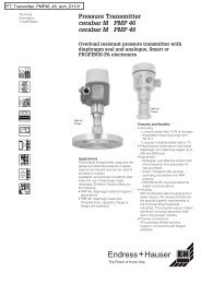
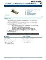
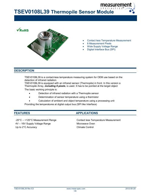
<strong>TSEV0108L39</strong> <strong>Thermopile</strong> <strong>Sensor</strong> <strong>Module</strong><br />
DESCRIPTION<br />
� Contact less Temperature Measurement<br />
� 8 Measurement Pixels<br />
� Wide Supply Voltage Range<br />
� Digital Interface Bus (SPI)<br />
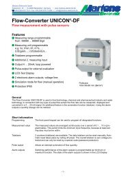
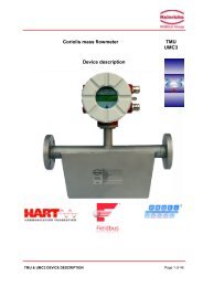
<strong>TSEV0108L39</strong> is a contact-less temperature measuring system for OEM use based on the<br />
detection of infrared radiation.<br />
<strong>TSEV0108L39</strong> is equipped with an infrared sensor (<strong>Thermopile</strong>) in front. In this version a<br />
<strong>Thermopile</strong> Array, including 8 pixels, is used. It has to be pointed at the target object<br />
The basic working principle is:<br />
� Detection of infrared radiation with a <strong>Thermopile</strong> sensor<br />
� Determination of sensor temperature using a thermistor<br />
� Calculation of ambient and object temperature using a processing unit<br />
Providing the temperatures at digital output bus (SPI like Interface)<br />
FEATURES APPLICATIONS<br />
-20°C – +120°C Measurement Range Contact less Temperature Measurement<br />
4V – 16V Supply Voltage Range Microwave Oven<br />
Up to 2°C Accuracy Climate Control<br />
<strong>TSEV0108L39</strong> Rev E3 www.meas-spec.com 2012-05-29<br />
1/8
<strong>TSEV0108L39</strong> <strong>Thermopile</strong> <strong>Sensor</strong> <strong>Module</strong><br />
ABSOLUTE MAXIMUM RATINGS<br />
Absolute maximum ratings are limiting values of permitted operation and should never be exceeded under the worst<br />
possible conditions either initially or consequently. If exceeded by even the smallest amount, instantaneous<br />
catastrophic failure can occur. And even if the device continues to operate satisfactorily, its life may be considerably<br />
shortened.<br />
Parameter Symbol Conditions Min Typ Max Unit<br />
Supply Voltage Vcc Measured versus GND -0.3 16 V<br />
Operating Temperature Top -10 +85 °C<br />
Storage Temperature Tstor -30 +85 °C<br />
Humidity HumL -30°C - +50°C 85 %<br />
Humidity HumH +50°C - +85°C 50 %<br />
SENSOR CHARACTERISTICS<br />
If not otherwise noted, 25°C ambient temperature, 5V supply voltage were applied.<br />
Parameter Symbol Conditions Min Typ Max Unit<br />
Total Field of View T_FOV Over all 8 Pixels 40 °<br />
Individual Field of View P_FOV Field of View of one Pixel 3.5 °<br />
Focal length f 3.9 mm<br />
OPERATING CONDITIONS<br />
Parameter Symbol Conditions Min Typ Max Unit<br />
Supply voltage Vcc Measured versus GND 4 5 6 V<br />
Supply Current I<br />
Full ambient temp. range, no<br />
output load<br />
10 15 mA<br />
Humidity HumL -30°C - +50°C 85 %<br />
Humidity HumH +50°C - +85°C 50 %<br />
INTERFACE CHARACTERISTICS<br />
Parameter Symbol Conditions Min Typ Max Unit<br />
Clock Rate (SPI) FSPI 100 kHz<br />
Data Output Rate<br />
(New Measurement Data of all 8<br />
Pixels available)<br />
OPERATIONAL CHARACTERISTICS<br />
Fout 1 Hz<br />
Parameter Symbol Conditions Min Typ Max Unit<br />
Object Temperature Range Tobj -20 +120 °C<br />
Ambient Temperature Range Tamb 0 +85 °C<br />
Resolution Res 0.1 °C<br />
Standard Start-Up Time tStart<br />
Time from turning on supply<br />
3 5 s<br />
Accuracy tolerance when<br />
Tambient = 25°C ±5°C<br />
ΔT<br />
to first measurement<br />
-5°C < Tobject < +5°C ±2 1)<br />
Outside above range ±4 1)<br />
1) Valid for a distance of 100mm and black body size of 150mm x 150mm.<br />
<strong>TSEV0108L39</strong> Rev E3 www.meas-spec.com 2012-05-29<br />
2/8<br />
°C<br />
°C
<strong>TSEV0108L39</strong> <strong>Thermopile</strong> <strong>Sensor</strong> <strong>Module</strong><br />
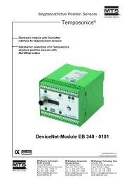
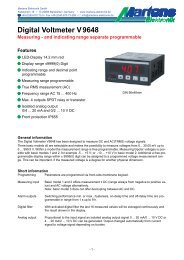
MECHANICAL DIMENSIONS<br />
TERMINALS<br />
Only use hatched areas for mechanical assembly (screws, nuts, etc).<br />
Connector: JST B5B-PH-K-S(LF)(SN)<br />
Pin Name Desription Type<br />
1 GND Supply Ground Supply<br />
2 MISO Data Out Output<br />
3 MOSI Data In Input<br />
4 CLK Clock Input<br />
5 VDD Supply Voltage Supply<br />
1 5<br />
<strong>TSEV0108L39</strong> Rev E3 www.meas-spec.com 2012-05-29<br />
3/8
<strong>TSEV0108L39</strong> <strong>Thermopile</strong> <strong>Sensor</strong> <strong>Module</strong><br />
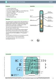
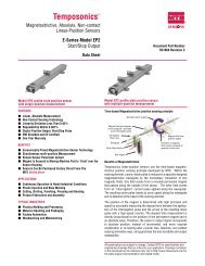
BLOCK DIAGRAM<br />
FIELD OF VIEW<br />
ANGLE OF PIXELS<br />
<strong>Thermopile</strong><br />
8 <strong>Thermopile</strong> <strong>Sensor</strong>s<br />
<strong>TSEV0108L39</strong> Rev E3 www.meas-spec.com 2012-05-29<br />
4/8<br />
MCU<br />
SPI like<br />
Interface<br />
Clk<br />
MOSI<br />
MISO<br />
1 2 3 4 5 6 7 8<br />
19,03 13,84 8,41 2,82 -2,82 -8,41 -13,84 -19,03<br />
Supply
<strong>TSEV0108L39</strong> <strong>Thermopile</strong> <strong>Sensor</strong> <strong>Module</strong><br />
FUNCTION<br />
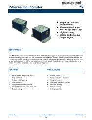
SPI INTERFACE<br />
PHYSICAL INTERFACE PARAMETERS<br />
Parameter Symbol Conditions Min Typ Max Unit<br />
Baudrate FSPI 10 200 kHz<br />
Data Bits 8<br />
Edge Rising<br />
Chip Select No<br />
Input Voltage Low 0.8 V<br />
Input Voltage High 2.8 3.6 V<br />
Output Current High @ 2.8V 1 mA<br />
Output Current Low @ 0.8V 1 mA<br />
SPI CONNECTION<br />
CLK<br />
MOSI<br />
Master <strong>TSEV0108L39</strong><br />
MISO<br />
SPI SIGNAL TIMING DESCRIPTION<br />
CLK<br />
MOSI<br />
MISO<br />
MOSI = Master Out � Slave In<br />
MISO = Master In � Slave Out<br />
GND<br />
MSB LSB<br />
7 6 5 4 3 2 1 0<br />
7 6 5 4 3 2 1 0<br />
<strong>TSEV0108L39</strong> Rev E3 www.meas-spec.com 2012-05-29<br />
5/8<br />
CLK<br />
MOSI<br />
MISO<br />
GND
<strong>TSEV0108L39</strong> <strong>Thermopile</strong> <strong>Sensor</strong> <strong>Module</strong><br />
INTERNAL RESET<br />
The internal SPI status is reset to idle state if one of the following conditions occur:<br />
� 100ms without receiving data<br />
� Reset due to cycling of supply voltage<br />
FILTER CIRCUITRY<br />
Capacitors are added to the following lines in to reduce noise/spikes in order to provide<br />
stable SPI transmission even in EMC affected environment:<br />
� CLK<br />
� MOSI<br />
A 10nF capacitor is added parallel to ground potential.<br />
SPI SIGNAL SEQUENCE<br />
Reading Temperature of Pixel 1<br />
Nr. MOSI MISO Direction Description<br />
1 0xA1 --- M � S Sending Command (See Command Reference)<br />
Wait at least 150us to arrange temperature data<br />
2 0XFF 0xXX M � S Receiving High Byte (Send 0xFF while receiving)<br />
Wait at least 150us to arrange temperature data<br />
3 0XFF 0xXX M � S Receiving Low Byte (Send 0xFF while receiving)<br />
EXAMPLE FOR 5V SPI INTERFACE LINE<br />
The sensor can not be connected directly to a SPI interface with 5V levels. Therefore the<br />
following circuitry is suggested. The Baudrate should be limited to 20kHz.<br />
CLK<br />
MOSI<br />
Master TSEV0108<br />
MISO<br />
GND<br />
1kOhm<br />
1kOhm<br />
<strong>TSEV0108L39</strong> Rev E3 www.meas-spec.com 2012-05-29<br />
6/8<br />
2kOhm<br />
2kOhm<br />
CLK<br />
MOSI<br />
MISO<br />
GND
<strong>TSEV0108L39</strong> <strong>Thermopile</strong> <strong>Sensor</strong> <strong>Module</strong><br />
AMBIENT AND OBJECT MEASUREMENT<br />
Please refer following table for SPI commands to read object temperature and ambient<br />
temperature. Both values are transmitted in tenth of degrees.<br />
All temperature read outs are to be interpreted as twos complement.<br />
Com Description Reply Bytes<br />
0xA0 <strong>Sensor</strong> Temperature <strong>Sensor</strong> temperature in hundredth of degrees Celsius 2<br />
0xA1 Temperature Pixel 1 Temp. at pixel position 1 in tenth of degree Celsius 2<br />
0xA2 Temperature Pixel 2 Temp. at pixel position 2 in tenth of degree Celsius 2<br />
0xA3 Temperature Pixel 3 Temp. at pixel position 3 in tenth of degree Celsius 2<br />
0xA4 Temperature Pixel 4 Temp. at pixel position 4 in tenth of degree Celsius 2<br />
0xA5 Temperature Pixel 5 Temp. at pixel position 5 in tenth of degree Celsius 2<br />
0xA6 Temperature Pixel 6 Temp. at pixel position 6 in tenth of degree Celsius 2<br />
0xA7 Temperature Pixel 7 Temp. at pixel position 7 in tenth of degree Celsius 2<br />
0xA8 Temperature Pixel 8 Temp. at pixel position 8 in tenth of degree Celsius 2<br />
EXAMPLE OF TEMPERATURE CALCULATION<br />
For reading object temperature of pixel 3 send: 0xA3<br />
Return values i.e.:<br />
Byte(0) = 0x02<br />
Byte(1) = 0xB0<br />
Temperature Tobj = (256 * Byte(0) + Byte(1)) / 10 = (256 * 2 + 11) / 10 = 52,3°C<br />
OUT OF TEMPERATURE RANGE INDICATION<br />
Com Description Reply Bytes<br />
0xA0 <strong>Sensor</strong> Temperature < 0°C 0x8001 2<br />
0xA0 <strong>Sensor</strong> Temperature > 85°C 0x8002 2<br />
0xA1 – 0xA8 Pixel Temperature < -20°C 0x8003 2<br />
0xA1 – 0xA8 Pixel Temperature > +120°C 0x8004 2<br />
ORDER INFORMATION<br />
Please order this product using following:<br />
Part Number Part Description<br />
G-TPMO-014 <strong>TSEV0108L39</strong><br />
<strong>TSEV0108L39</strong> Rev E3 www.meas-spec.com 2012-05-29<br />
7/8
<strong>TSEV0108L39</strong> <strong>Thermopile</strong> <strong>Sensor</strong> <strong>Module</strong><br />
EMC<br />
Due to the use of these modules for OEM application no CE declaration is done.<br />
Especially line coupled disturbances like surge, burst, HF etc. cannot be removed by the<br />
module due to the small board area and low price feature. There is no protection circuit<br />
against reverse polarity or over voltage implemented.<br />
The module will be designed using capacitors for blocking and ground plane areas in order<br />
to prevent wireless coupled disturbances as good as possible.<br />
DEFINITIONS AND DISCLAIMERS<br />
� Application information – Applications that are described herein for any of these products are for<br />
illustrative purpose only. MEAS Deutschland GmbH makes no representation or warranty that such<br />
applications will be suitable for the specified use without further testing or modification.<br />
� Life support applications – These products are not designed for use in life support appliances,<br />
devices, or systems where malfunctions of these products can reasonably be expected to result in<br />
personal injury.<br />
MEAS Deutschland GmbH customers using or selling this product for use in such applications do<br />
so at their own risk and agree to fully indemnify MEAS Deutschland GmbH for any damages<br />
resulting from such improper use or sale.<br />
TECHNICAL CONTACT INFORMATION<br />
NORTH AMERICA EUROPE ASIA<br />
Measurement Specialties, Inc.<br />
1000 Lucas Way<br />
Hampton, VA 23666<br />
United States<br />
Phone: +1-800-745-8008<br />
Fax: +1-757-766-4297<br />
Email: sales@meas-spec.com<br />
Web: www.meas-spec.com<br />
MEAS Deutschland GmbH<br />
Hauert 13<br />
D-44227 Dortmund<br />
Germany<br />
Phone: +49-(0)231-9740-0<br />
Fax: +49-(0)231-9740-20<br />
Email: info.de@meas-spec.com<br />
Web: www.meas-spec.com<br />
Measurement Specialties China Ltd.<br />
No. 26, Langshan Road<br />
High-tech Park (North)<br />
Nanshan District, Shenzhen 518057<br />
China<br />
Phone: +86-755-33305088<br />
Fax: +86-755-33305099<br />
Email: info.cn@meas-spec.com<br />
Web: www.meas-spec.com<br />
The information in this sheet has been carefully reviewed and is believed to be accurate; however, no responsibility is assumed for<br />
inaccuracies. Furthermore, this information does not convey to the purchaser of such devices any license under the patent rights to the<br />
manufacturer. Measurement Specialties, Inc. reserves the right to make changes without further notice to any product herein. Measurement<br />
Specialties, Inc. makes no warranty, representation or guarantee regarding the suitability of its product for any particular purpose, nor does<br />
Measurement Specialties, Inc. assume any liability arising out of the application or use of any product or circuit and specifically disclaims<br />
any and all liability, including without limitation consequential or incidental damages. Typical parameters can and do vary in different<br />
applications. All operating parameters must be validated for each customer application by customer’s technical experts. Measurement<br />
Specialties, Inc. does not convey any license under its patent rights nor the rights of others.<br />
<strong>TSEV0108L39</strong> Rev E3 www.meas-spec.com 2012-05-29<br />
8/8