Active Antenna Systems - CommScope
Active Antenna Systems - CommScope
Active Antenna Systems - CommScope

Create successful ePaper yourself
Turn your PDF publications into a flip-book with our unique Google optimized e-Paper software.
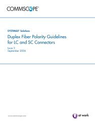
<strong>Active</strong> <strong>Antenna</strong> <strong>Systems</strong>
Leader in active antennas<br />
World Class<br />
<strong>Antenna</strong>s<br />
• <strong>CommScope</strong> is a world leader in antenna designs<br />
• Pioneering active antennas for over 10 years<br />
• Joint development with Ubidyne since 2007<br />
• <strong>CommScope</strong> has developed industry-leading technology in remote<br />
radioheads, filters, amplifiers, and wideband linearization<br />
• Combined expertise positions <strong>CommScope</strong> as a global leader in<br />
active antennas<br />
PRIVATE AND CONFIDENTIAL © 2011 <strong>CommScope</strong>, Inc<br />
World Class<br />
Transceivers<br />
Amplifiers,<br />
Filters,<br />
Linearization<br />
World Class<br />
<strong>Active</strong><br />
<strong>Antenna</strong>s<br />
2
<strong>Active</strong> <strong>Antenna</strong> Design Challenges<br />
PRIVATE AND CONFIDENTIAL © 2011 <strong>CommScope</strong>, Inc<br />
Filter Design<br />
Size,<br />
Insertion Loss<br />
Mechanical<br />
Design<br />
Interconnects,<br />
Thermal<br />
Amplifier<br />
Design<br />
Efficiency,<br />
Bandwidth<br />
<strong>Antenna</strong> Design<br />
Beam Patterns,<br />
<strong>Active</strong>/Passive<br />
Combinations,<br />
Graceful<br />
Degradation<br />
All are <strong>CommScope</strong> core competencies<br />
3
Wireless Network Evolution<br />
BTS<br />
(Channel<br />
Cards,<br />
Radios,<br />
Amplifiers,<br />
Filters)<br />
The Past<br />
Conventional BTS<br />
RET<br />
Masthead<br />
Amplifiers<br />
Coaxial Cable<br />
Passive<br />
<strong>Antenna</strong>s<br />
COAX<br />
Jumpers<br />
PRIVATE AND CONFIDENTIAL © 2011 <strong>CommScope</strong>, Inc<br />
Base Station<br />
Server<br />
Channel<br />
Cards<br />
The Present<br />
Remote Radio Head<br />
RET<br />
Passive<br />
<strong>Antenna</strong>s<br />
COAX<br />
Cables<br />
Remote<br />
Radio Head<br />
Base Station<br />
Server<br />
Channel<br />
Cards<br />
The Future<br />
<strong>Active</strong> <strong>Antenna</strong>s<br />
Minimizing the hardware footprint is a key benefit to active antenna design<br />
4
Pioneering Technology<br />
PRIVATE AND CONFIDENTIAL © 2011 <strong>CommScope</strong>, Inc<br />
Extremely Simple, Digital Architecture<br />
• RRH functionality integrated and distributed into the antenna<br />
• Transceiver on each element — redundant architecture<br />
• Digital IF from a central DSP unit, C-Hub<br />
• Future-proof, multi-standard, soft-configurable<br />
• Standard sized antenna — fiber feed from the base band radio<br />
• Improved MTBF and network reliability<br />
– Redundant radio architecture<br />
– Distributed low-power transceivers<br />
– Custom chip integration<br />
– Passive cooling<br />
<strong>Antenna</strong> Embedded Radio<br />
• Direct control of signals to each radiator enables digital elevation<br />
beam control at baseband — capacity improvements<br />
5
Normal Pattern<br />
5°tilt<br />
A Self-Healing Response To A Failure<br />
E1<br />
E1’<br />
E2<br />
…........<br />
E2’<br />
En<br />
En’<br />
-5dB<br />
-10dB<br />
-15dB<br />
-20dB<br />
PRIVATE AND CONFIDENTIAL © 2011 <strong>CommScope</strong>, Inc<br />
Single Failure<br />
Before Compensation<br />
5°tilt<br />
E1<br />
E1’<br />
-5dB<br />
-10dB<br />
-15dB<br />
E2<br />
-20dB E2’<br />
FAILED<br />
ELEMENT<br />
…........<br />
En<br />
En’<br />
2°tilt<br />
Unmatched Service Life Due To Built-In Redundancy And<br />
Unique Pattern Compensation Capability<br />
Single Failure<br />
After Compensation<br />
E1<br />
E1’<br />
E2<br />
E2’<br />
FAILED<br />
ELEMENT<br />
…........<br />
En<br />
En’<br />
-5dB<br />
-10dB<br />
-15dB<br />
-20dB<br />
Self-Healing!<br />
4dB<br />
• First upper side lobe<br />
suppressed automatically<br />
• Tilt adjusted to maintain<br />
cell coverage<br />
6
Dynamic Electronic Pattern Control<br />
Tilt by Carrier- Vertical Sectorization<br />
• Multiple beams per carrier enables vertical<br />
sub-sectorization for capacity enhancement<br />
Tilt by Standard– Air Interface<br />
#1 #2 #3<br />
• Tilt per standard (GSM/UMTS/LTE)<br />
- Simplifies RAN sharing<br />
PRIVATE AND CONFIDENTIAL © 2011 <strong>CommScope</strong>, Inc<br />
Tx / Rx Tilt Optimization<br />
• Significant capacity improvement<br />
- Improves handset battery life<br />
Beam Shape Control<br />
Unique capability to optimize signal patterns of each carrier of each sector<br />
for Maximum Network Performance<br />
Tx<br />
Pattern A Pattern B<br />
Rx<br />
Tx<br />
Rx<br />
7
High-band <strong>Active</strong> <strong>Antenna</strong> Currently in<br />
Development<br />
304 mm (11.8 in)<br />
1300 mm (51.2 in )<br />
PRIVATE AND CONFIDENTIAL © 2011 <strong>CommScope</strong>, Inc<br />
196 mm (6.9 in)<br />
• Radio modules are field<br />
replaceable<br />
• <strong>Antenna</strong> array elements identical<br />
to current Andrew passive<br />
element arrays<br />
• Multi-standard<br />
• 1800, 1900, AWS and 2600 MHz<br />
models in the roadmap<br />
8
<strong>Active</strong>-Passive <strong>Antenna</strong>s in Development<br />
High Band<br />
<strong>Active</strong><br />
<strong>Antenna</strong><br />
Array<br />
Power Connector<br />
PRIVATE AND CONFIDENTIAL © 2011 <strong>CommScope</strong>, Inc<br />
High Band<br />
Passive<br />
<strong>Antenna</strong><br />
Array<br />
CPRI/ORI<br />
• Passive and <strong>Active</strong><br />
antenna arrays in a<br />
dual-column arrangement<br />
• Design borrows from<br />
<strong>CommScope</strong>’s industry<br />
leading antenna arrays<br />
• Broadband elements<br />
to cover low-band or<br />
high-band applications<br />
9
700 MHz <strong>Active</strong> <strong>Antenna</strong> General Specifications<br />
• 1.8 m (6 ft) antenna<br />
• 12° elevation beamwidth<br />
• 65° azimuth beamwidth<br />
• 16.5 dBi gain<br />
• 15 W RF output power per array (6 x 2.5 W)<br />
• 30 W RF output power total (2 x 15 W)<br />
• Single 10 MHz LTE carrier<br />
• 6 dual-polarized radiating elements with<br />
12 total Tx/Rx paths<br />
PRIVATE AND CONFIDENTIAL © 2011 <strong>CommScope</strong>, Inc<br />
1.8 m (6 ft)<br />
700 MHz<br />
<strong>Active</strong><br />
<strong>Antenna</strong><br />
LTE Trial<br />
10
700 MHz <strong>Active</strong> <strong>Antenna</strong> Pattern Measurements<br />
• Azimuth and elevation patterns<br />
recorded in May, 2011<br />
• Elevation beam down-tilting<br />
characterization completed for<br />
0°to 14°range<br />
• Elevation pattern shaping<br />
confirmed with excellent<br />
agreement to theoretical patterns<br />
• Pattern compensation<br />
demonstrated for simulated<br />
transceiver failures<br />
PRIVATE AND CONFIDENTIAL © 2011 <strong>CommScope</strong>, Inc<br />
700 MHz <strong>Active</strong> <strong>Antenna</strong> in Anechoic Chamber<br />
11
700 MHz <strong>Active</strong> <strong>Antenna</strong> Azimuth Pattern<br />
PRIVATE AND CONFIDENTIAL © 2011 <strong>CommScope</strong>, Inc<br />
Excellent cross-polarization patterns<br />
12
700 MHz <strong>Active</strong> <strong>Antenna</strong> Elevation Pattern<br />
Excellent elevation patterns and upper side-lobe performance with down tilt<br />
PRIVATE AND CONFIDENTIAL © 2011 <strong>CommScope</strong>, Inc<br />
13
Environmental Verification Testing:<br />
Thermal Characterization and Burn-In<br />
48 hour full power burn-in testing<br />
PRIVATE AND CONFIDENTIAL © 2011 <strong>CommScope</strong>, Inc<br />
High temperature (50°C) thermal testing<br />
14
EMC Testing<br />
PRIVATE AND CONFIDENTIAL © 2011 <strong>CommScope</strong>, Inc<br />
• Radiated emissions compliance<br />
demonstrated for CISPR22 Class B for<br />
10 m (32.8 ft) distance:<br />
• 30 to 230 MHz (30 dBμV per m)<br />
• 230 to 1000 MHz (37 dBμV per m)<br />
15
Field Trial Installation<br />
700 MHz<br />
<strong>Active</strong> <strong>Antenna</strong><br />
PRIVATE AND CONFIDENTIAL © 2011 <strong>CommScope</strong>, Inc<br />
16
<strong>Active</strong> <strong>Antenna</strong> Product Roadmap<br />
1 st Gen<br />
<strong>Active</strong> Arrays<br />
2 nd Gen<br />
<strong>Active</strong> – Passive<br />
PRIVATE AND CONFIDENTIAL © 2011 <strong>CommScope</strong>, Inc<br />
3 rd Gen<br />
<strong>Active</strong> – <strong>Active</strong><br />
&<br />
<strong>Active</strong>-<strong>Active</strong>-<br />
Passive<br />
4 th Gen<br />
Multi-column<br />
beamforming<br />
2011 2012 2013 2014 2015<br />
2016<br />
17
PRIVATE AND CONFIDENTIAL © 2011 <strong>CommScope</strong>, Inc<br />
Thank You<br />
18