Service Bulletin - Hartzell Engine Technologies
Service Bulletin - Hartzell Engine Technologies
Service Bulletin - Hartzell Engine Technologies
Create successful ePaper yourself
Turn your PDF publications into a flip-book with our unique Google optimized e-Paper software.
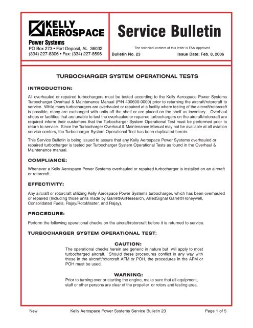
INTRODUCTION:<br />
TURBOCHARGER SYSTEM OPERATIONAL TESTS<br />
All overhauled or repaired turbochargers must be tested according to the Kelly Aerospace Power Systems<br />
Turbocharger Overhaul & Maintenance Manual (P/N 400600-0000) prior to returning the aircraft/rotorcraft to<br />
service. While many turbochargers are overhauled or repaired at a facility where testing of the aircraft/rotorcraft<br />
is possible, many are exchanged with units off the shelf or are placed on the shelf as inventory. Overhaul<br />
shops or facilities that are unable to test the overhauled or repaired turbochargers on the aircraft/rotorcraft are<br />
required inform their customers that the Turbocharger System Operational Test must be performed prior to<br />
return to service. Since the Turbocharger Overhaul & Maintenance Manual may not be available at all aviation<br />
service centers, the Turbocharger System Operational Test has been duplicated herein.<br />
This <strong>Service</strong> <strong>Bulletin</strong> is being issued to assure that any Kelly Aerospace Power Systems overhauled or<br />
repaired turbocharger is tested per Turbocharger System Operational Tests as found in the Overhaul &<br />
Maintenance manual.<br />
COMPLIANCE:<br />
Whenever a Kelly Aerospace Power Systems overhauled or repaired turbocharger is installed on an aircraft<br />
or rotorcraft.<br />
EFFECTIVITY:<br />
Any aircraft or rotorcraft utilizing Kelly Aerospace Power Systems turbocharger, which has been overhauled<br />
or repaired (Including those units made by Garrett/AirResearch, AlliedSignal Garrett/Honeywell,<br />
Consolidated Fuels, Rajay/RotoMaster, and Rajay).<br />
PROCEDURE:<br />
Perform the following operational checks on the aircraft/rotorcraft before it is returned to service.<br />
TURBOCHARGER SYSTEM OPERATIONAL TEST:<br />
<strong>Service</strong> <strong>Bulletin</strong><br />
The technical content of this letter is FAA Approved<br />
<strong>Bulletin</strong> No. 23 Issue Date: Feb. 8, 2006<br />
CAUTION:<br />
The operational checks herein are generic in nature but will apply to most<br />
turbocharged aircraft. Should these procedures conflict in any way with<br />
those in the aircraft/rotorcraft AFM or POH, the procedures in the AFM or<br />
POH must be used.<br />
WARNING:<br />
Prior to turning over or starting the engine, make sure that all equipment,<br />
staff or other persons are clear of the propeller or rotors and testing area.<br />
New Kelly Aerospace Power Systems <strong>Service</strong> <strong>Bulletin</strong> 23 Page 1 of 5
PROCEDURE: (cont’d)<br />
PRE-LUBRICATION OF TURBOCHARGER:<br />
All overhauled or repaired turbochargers must be pre-lubricated prior to installation and prior<br />
to engine start. Preheat engine in extremely cold conditions.<br />
A. Just prior to mounting, prime the turbocharger with engine oil by filling the oil inlet of the<br />
turbocharger bearing housing and rotating the T-wheel by hand to coat the bearings.<br />
B. Make sure the oil inlet line is clean and free of obstructions. Crank the engine over with<br />
the ignition off and the fuel in the idle cut off position until oil comes out of the turbocharger<br />
drain line. Connect the drain line. Start the engine and observe oil pressure.<br />
Should oil pressure not rise to 10 psi within 5 seconds, shut engine down and investigate<br />
the cause. When proper oil pressure is reached, idle the engine for 5 minutes minimum.<br />
Shut engine down and check for oil leaks.<br />
GROUND RUN AND SETUP:<br />
Perform a ground run-up to check basic performance and integrity of the turbocharging system.<br />
Prior to accomplishing this procedure, check the appropriate aircraft service or maintenance<br />
manual for the ground run procedures and check the appropriate AFM or POH for the applicable<br />
preflight procedures. Should these tests reveal improper conditions, additional information<br />
on troubleshooting, may be found in the Kelly Aerospace, Aircraft Turbocharger and Control<br />
Systems Reference With Troubleshooting Guide Handbook, P/N 400888-0000.<br />
WARNING:<br />
Prior to starting and running the engine, make sure that an appropriate<br />
testing area is selected and that all equipment, staff or other persons are<br />
clear of the propeller or rotors.<br />
CAUTION:<br />
It is not advisable to perform the ground run-up or Pre-lubrication on an<br />
overhauled or repaired turbocharger in extremely cold weather conditions.<br />
Preheat the aircraft prior to accomplishing these tests.<br />
A. Before beginning these tests, read the applicable sections of the appropriate service or<br />
maintenance manuals as well as the AFM and POH regarding run up procedures. Should<br />
any step herein conflict from the AFM or POH procedures, use that information.<br />
B. Start the engine and observe oil pressure. Should oil pressure not rise to 10 psi within<br />
5 seconds, shut engine down and investigate the cause. When proper oil pressure is<br />
reached, idle the engine for 5 minutes. Allow the oil temperature to stabilize at 120 deg. F<br />
(or as called out in the AFM or POH) and the oil pressure above 10 psi. Stay within the<br />
minimum and maximum limitations!<br />
Note:<br />
Blue or white smoke may appear from the exhaust during initial start and<br />
run up. Unless the smoke is extreme or appears in combination with an<br />
oil pressure drop, it can be considered normal. Lubricants used in<br />
assembly may make light smoke for up to 30 minutes operation.<br />
New Kelly Aerospace Power Systems <strong>Service</strong> <strong>Bulletin</strong> 23 Page 2 of 5
GROUND RUN AND SETUP: (CONT’D)<br />
C. Advance the throttle slowly in 500 RPM increments until takeoff power is reached. Pause<br />
at each RPM step and allow the engine to stabilize (the turbocharger will lag slightly).<br />
At each RPM step, observe oil pressure, oil temperature, TIT/EGT, and manifold pressure<br />
(MAP). These indications should not fluctuate but remain steady. Oil pressure above<br />
idle should be a minimum of 30 psi. Take care not to overboost the engine when<br />
approaching takeoff power, throttle movement at power is sensitive. Consult the applicable<br />
AFM or POH and determine and record TIT/EGT and MAP at takeoff power.<br />
D. Retard the throttle slowly to idle. Great care should be taken not to reduce power rapidly.<br />
For 400 series (Garrett style) turbochargers, operate the engine at idle for 3 to 5 minutes<br />
to allow the turbine wheel to slow down. No idle time is required on 600 series<br />
(Rajay/RotoMaster style) turbochargers.<br />
E. Shut down the engine and inspect for oil leaks and general security. If installed, tap<br />
V-band coupling to assure seating and re-torque nut. (See Table 1 page 5) If proper<br />
TIT/EGT or MAP was not achieved, investigate cause. Compare all engine parameters<br />
to the requirements in the AFM or POH and if necessary, perform an engine setup per<br />
the applicable aircraft service or maintenance manual. If required, repeat this check.<br />
OPERATIONAL FLIGHT TEST:<br />
WARNING:<br />
The operational flight test must be performed by an appropriately rated,<br />
current pilot familiar with the aircraft/rotorcraft and the requirements<br />
and limitations of the AFM or POH.<br />
Perform a flight test to confirm operation of the turbocharging system. While there are<br />
many types of turbocharging systems, they can be categorized as Manual or Automatic.<br />
MANUAL SYSTEMS: The most basic form of manual control is the fixed bleed system<br />
which allows exhaust gas to continuously escape through an orifice of predetermined size.<br />
The size of the orifice determines the critical altitude of the engine. More complex manual<br />
systems will have a method to adjust the wastegate through use of a vernier cable. These<br />
systems may or may not incorporate a pressure relief valve so great care must be taken<br />
not to overboost the engine.<br />
AUTOMATIC SYSTEMS: The automatic systems that control turbocharger operation use<br />
air pressure sensors installed at various points in the induction system. They in turn will<br />
cause changes to the oil pressure that controls the position of the wastegate. There are<br />
many different systems therefore, it is very important that the mechanic and pilot understand<br />
what manifold pressures he should expect when full throttle is applied for takeoff.<br />
PRECAUTIONS:<br />
1. Do not exceed the red-line temperature limitations during takeoff, climb and max<br />
performance cruise power operation.<br />
2. Keep the cylinder head temperature (CHT), Oil temperature, turbine inlet temp-<br />
erature (TIT or EGT) below the max limits stated in the aircraft AFM or POH .<br />
3. Whenever mixture is adjusted, rich or lean, it should be done slowly.<br />
3. Unless it conflicts with the aircraft AFM or POH, always return the mixture<br />
slowly to full rich before increasing the power setting.<br />
4. At all times, caution must be taken not to shock cool the cylinders. Do not allow<br />
a CHT change of more than 50 deg. F per minute.<br />
5. The throttle(s) must be operated smoothly or the engine(s) will surge. Smooth<br />
and steady operation of the mixture control will assure that TIT/EGT limits are<br />
not exceeded.<br />
New Kelly Aerospace Power Systems <strong>Service</strong> <strong>Bulletin</strong> 23 Page 3 of 5
OPERATIONAL FLIGHT TEST: (CONT’D)<br />
Prepare the aircraft for the test flight. Perform a preflight and run up according to the appropriate aircraft<br />
AFM or POH. Proceed with normal takeoff. Due to the special nature of rotorcraft, the flight test may be<br />
substantially different, however a basic check of performance per the AFM or POH must be applied.<br />
A. TAKEOFF: Using AFM or POH data, establish a max power takeoff and record engine<br />
parameters with close attention to MAP. If applicable reduce power within time limits.<br />
Manual systems will require constant attention. Extreme care must be taken not to<br />
overboost the engine. Should an overboost occur, refer to the latest revision of<br />
Lycoming <strong>Service</strong> <strong>Bulletin</strong> 369 or Teledyne Continental Motors <strong>Service</strong> <strong>Bulletin</strong> 67-12.<br />
B. CLIMB: Using AFM or POH data, establish max power climb, record the engine<br />
parameters each 1000 feet, with close attention to MAP and TIT/EGT. Remember, to<br />
increase power, enrich the mixture, increase RPM, and then MAP. Maintain a<br />
consistent climb until critical altitude is reached, however do not exceed max CHT.<br />
Without changing power setting, climb above critical and note that MAP decreases.<br />
C. CRUISE: Using AFM or POH data, establish a max performance cruise and then an<br />
economy cruise setting. Record engine parameters, fuel flow, and aircraft speed.<br />
Compare to the AFM or POH published information.<br />
D. DESCENT AND LANDING: Using AFM or POH data, descend and land. Please note,<br />
manual systems will require constant attention. For decent, do not pull throttle(s) back<br />
rapidly, do not allow a CHT change of more than 50 deg. F per minute, and remember<br />
to decrease power decrease MAP and then RPM. For landing, follow the procedures<br />
in the AFM or POH.<br />
RETURN TO SERVICE:<br />
After landing, determine turbocharger performance using the data recorded. Any discrepancy<br />
noted must be investigated and a remedy applied before returning the aircraft to service. In<br />
most cases, improper or low performance will be related to conditions other than the turbocharger,<br />
in order of importance, consult the aircraft service or maintenance manual, Kelly<br />
Aerospace, Aircraft Turbocharger and Control Systems Reference With Trouble-shooting<br />
Guide Handbook, P/N 400888-0000, and the Kelly Aerospace Overhaul manual. If the<br />
operational test procedures are satisfactory, make the appropriate logbook entries and<br />
return the aircraft to service.<br />
DISPOSITION OF INVENTORY:<br />
Any turbocharger which has been overhauled or repaired and placed in inventory must be delivered with a<br />
copy of this <strong>Service</strong> <strong>Bulletin</strong>. Download the <strong>Service</strong> <strong>Bulletin</strong> file at http://www.kellyaerospace.com/, select<br />
service bulletins and turbocharger system components. Additional copies may be made from the file.<br />
CONTACT INFORMATION:<br />
If you have any questions concerning the instructions in this service bulletin, please contact Kelly<br />
Aerospace Power Systems Technical Support at 888-461-6077.<br />
Questions concerning aircraft or rotorcraft service or operation must be forwarded to the applicable<br />
manufacturer of that product.<br />
New Kelly Aerospace Power Systems <strong>Service</strong> <strong>Bulletin</strong> 23 Page 4 of 5
Table 1 - V-Band Clamp Torque<br />
Clamp P/N* Diameter mm Diameter in Nut Torque<br />
400500-925 235.0 9.25 110-130 in/lbs<br />
400720-775 196.9 7.75 40-60 in/lbs<br />
400720-685 174.0 6.85 40-60 in/lbs<br />
446397-775 196.9 7.75 110-130 in/lbs<br />
All KAPS 600 series (Rajay, RotoMaster)<br />
CF600391-00 ALL ALL 15-20 in/lbs<br />
* Part number etched on strap or check diameter.<br />
New Kelly Aerospace Power Systems <strong>Service</strong> <strong>Bulletin</strong> 23 Page 5 of 5


