CLOCKIT LANC LOGGER ALL601 - Ambient Recording
CLOCKIT LANC LOGGER ALL601 - Ambient Recording
CLOCKIT LANC LOGGER ALL601 - Ambient Recording

You also want an ePaper? Increase the reach of your titles
YUMPU automatically turns print PDFs into web optimized ePapers that Google loves.
1<br />
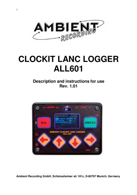
<strong>CLOCKIT</strong> <strong>LANC</strong> <strong>LOGGER</strong><br />
<strong>ALL601</strong><br />
Description and instructions for use<br />
Rev. 1.01<br />
<strong>Ambient</strong> <strong>Recording</strong> GmbH, Schleissheimer str 181c, D-80797 Munich, Germany
2<br />
USER MANUAL „<strong>LANC</strong> <strong>LOGGER</strong>” <strong>ALL601</strong><br />
The Lanc logger is a very small hand held timecode device for use in<br />
Film or TV. Its innovative timecode features makes it an ideal timecode<br />
source, logger and timecode conversion unit when working with DV and<br />
HDV cameras and computer based audio recorders with and without a<br />
timecode input/output. The <strong>LANC</strong> <strong>LOGGER</strong> can offer solutions both on<br />
location and in Post production.<br />
Timecode source with 0.2 ppm accuracy from <strong>Ambient</strong> Clockit XTAL Ref.<br />
The <strong>LANC</strong> <strong>LOGGER</strong> is a Clockit device and the VCTCXO Xtal reference<br />
can be calibrated to an accuracy of under 0.2 ppm relative to other<br />
Clockit units such as the Lockit box and the Controller. Timecode drift<br />
between boxes is well under 1 frame a day. A new IR port allows the<br />
device to be set with Timecode and offset checked, without cables, using<br />
the Aaton ASCII Protocol and the Controller ACC501.<br />
Using the Standard TC Lemo 5 pin interface socket with TC in, TC out,<br />
Tuning and ASCII port, the ALL 601 is fully compatible to all portable<br />
timecode equipment including the Aaton Origen C unit.<br />
The audio port with timecode as a burst or as a continous signal with<br />
adjustable timecode levels –55dB to 0dB (1mV to 0.5 Volt ) and with<br />
additional –20dB pad, allows connection to all camera audio inputs<br />
using Minijack or Cinch connectors, without overload and crosstalk<br />
Timecode logging from various sources. <strong>LANC</strong>, MIDI, LTC, Manual<br />
The <strong>LANC</strong> <strong>LOGGER</strong> is fitted with a 512 MB flash card and can write logs<br />
into this memory. Complex logs for use in Post production can be made,<br />
using camera start/stop signals, and the Record Run (Rec.Run.)<br />
timecode of the cassette from the <strong>LANC</strong> port of a Sony camera and<br />
logging to its accurate internal time of day (TOD). The LTC out of a<br />
camera can be used as Rec. Run. timecode source. The logger analyses<br />
the timecode and only logs when the camera is in record, not in playback<br />
or when spooling. Events can be Logged manually to TOD and given a<br />
value using the keys with ASCII symbols. The ALL is a mass storage<br />
device and the logs can be downloaded to a computer is via USB. The<br />
logs can be converted to a EDL using the CB EDL master Program.<br />
Timecode conversiom<br />
With the increasing use of a computer and USB audio hardware for<br />
portable recording or playback, the timecode conversion features in the<br />
ALL can be very useful. The following conversions are possible.
3<br />
Conversions<br />
<strong>LANC</strong> TC to MIDI TC (USB Port) and LTC (Lemo, Audio)<br />
<strong>LANC</strong> TC to LTC with or without OFFSET<br />
EXT LTC to MIDI TC (USB Port)<br />
EXT LTC to LTC with or without OFFSET<br />
INTERN GEN TC to MIDI TC (USB Port) MIDI<br />
MIDI TC (USB) to LTC with or without OFFSET<br />
EXT LTC to LTC with or without OFFSET<br />
Uses<br />
• A laptop computer is being used as an audio playback or recording<br />
device. The Playback TC is available as a MIDI Timecode. The ALL is<br />
connected to the USB port of the computer and converts the MIDI TC to<br />
LTC for transmission to a timecode slate etc.<br />
• A film camera is connected to an editing System (FCP, Avid Express) to<br />
digitalise the cassette. The <strong>LANC</strong> TC can be converted and transferrerd<br />
to the computer via MIDI TC or LTC. LTC on an audio track of the camera<br />
can be converted to MIDI TC and sent to the computer via USB.<br />
• The internal Generator TC of the ALL (TOD) can be used as timecode<br />
source (via MIDI) for a computer recording Audio.
4<br />
ESC / Enter<br />
Command Keys<br />
Batteries<br />
Mic/Audio<br />
TC out to Camera<br />
ALL 601<br />
PORTS AND<br />
ACCESS<br />
DEVICE DESCRIPTION<br />
Mic/ Audio<br />
TC/ Mic in<br />
IR Comms<br />
Display<br />
Lanc to<br />
Remote<br />
AUDIO INTERFACE AND LTC INPUT OUTPUT<br />
Lanc from<br />
Camera<br />
USB<br />
Cursor Keys<br />
Lemo: Aaton, <strong>Ambient</strong> TC Interface<br />
The audio interface ist a two channel unbalanced input/output with<br />
Electret power supply (5.6Volt) on channel 1 of the input, switchable<br />
LTC out on channel 2 output, and an auxiliary LTC input on channel 1<br />
(when the mike is not being used).<br />
The LTC level can be adjusted from 0db to –55db with an extra –20db<br />
switched pad at the LTC output to audio, allowing LTC input to every<br />
type of microphone or line input without distortion or crosstalk. On<br />
channel 1 at the mike side is a switchable Powering of 5.6 volts that<br />
covers the requirements of all Electret microphones.<br />
The LTC ouput on channel 2 can be set to either off, continous ,or burst,<br />
(triggered by the record on signal from camera <strong>LANC</strong>), allowing audio to<br />
be recorded on channel 2 aftewr the burst.<br />
• Electret Mike power supply<br />
• LTC output with adjustable levels,<br />
• LTC switchable as burst, continuous, or off<br />
• LTC auxiliary input
5<br />
Uses<br />
Audio track LTC recording<br />
To record the exact TOD (Userbits inserted from Logger) of the ALL to an<br />
audio track of the camera being used, thus allowing this timecode to used<br />
in post production to sync sound and picture.<br />
Note: <strong>Recording</strong> Audio track LTC can be done simultaneously to logging<br />
Burst LTC<br />
LTC can be recorded at the beginning of a take for 1 second, using the burst<br />
LTC triggered by the camera start/stop info from the <strong>LANC</strong> or external TC<br />
input. After this the Audio channel is free for audio recording ( 2 channel<br />
audio with Timecode)<br />
Logging using Aux. TC input .<br />
Using an external Rec.Run. LTC to make a log against ALL internal TOD.<br />
Internal timecode software filters and checks the LTC in signal and only<br />
makes a log when the camera is in record. Spooling or shot playback<br />
timecode does not trigger a log.<br />
<strong>LANC</strong> INTERFACE<br />
The ALL’s <strong>LANC</strong> interface can read the <strong>LANC</strong> signal of a Sony** camera<br />
and the through output allows a zoom control to still be connected to the<br />
camera via the ALL. The ALL takes its powering from the <strong>LANC</strong> socket,<br />
Note:Available current at the camera <strong>LANC</strong> socket is about 70mA at 5<br />
Volts. The ALL takes 50 mA. Leaving 20 mA for a zoom control, this is as<br />
adequate for most zoom controls but can lead to malfunction if more<br />
than 15mA is used.<br />
Alternative powering is through the Lemo socket with 6 to16 Volts<br />
voltage range.<br />
** other manufacturers using the Sony <strong>LANC</strong> protocol (Canon) do not<br />
adhere to the Sony protocol. Neither the message framerate nor<br />
timecode values are ouputted correctly. The ALL can only read the<br />
<strong>LANC</strong> from Sony cameras. Panasonic control M is only suitable for<br />
remote zoom connection and does not output Rec.Run. timecode values<br />
as does the Sony <strong>LANC</strong>.<br />
<strong>LANC</strong> Signals read<br />
Camera start stop<br />
Rec.Run. Timecode<br />
Any other available data that could be useful to log<br />
TIMER<br />
The ALL can be used to start and stop the camera at specific TODs<br />
allowing remote start and stop, for example slow motion shots**.<br />
**Not yet implemented
6<br />
Uses<br />
LOGGING. The ALL makes logs of Rec.Run. Timecode from the <strong>LANC</strong><br />
out of the camera gainst internal TOD. Ancilliary data such as cassette<br />
number, camera ID, (entered manually to the ALL), and Event Number,<br />
(automatically incremented) and RTC date and time are also recorded in<br />
the log. Log format is open so that future extensions and IXML<br />
conformity are possible. The TOD Timecode with the ancilliary data in<br />
the Userbits can be simultaneously recorded on a camera audio track.<br />
thus giving a second method of syncing audio and picture.<br />
The logs are stored on a built in 512MB flash card and can be<br />
downloaded through the USB port to any computer. They can then be<br />
converted to an EDL using the CB EDL master program which can then<br />
be used to sync the sound and video to a TOD timeline.<br />
A complete solution for FCP is being developed by Andreas Kiel of<br />
Spherico com.<br />
USB PORT<br />
The USB port is configured as a USB audio device and can be connected<br />
to any computer with a USB port.<br />
Uses<br />
External power supply of the ALL<br />
MIDI TC input and Output<br />
ALL program updates upload eg from www.ambient.de<br />
Mass storage download of logs<br />
KEYPAD AND IR PORT<br />
On the top of the ALL is are the keypad, display and Infra Red (IR)<br />
windows. In addition, the sockets and battery polarity are indicated.<br />
KEYS<br />
There are 6 keys used to configure the ALL and to call up system data,<br />
Some have additional special functions. A few functions such as<br />
jamming the internal TOD generator from Ext TC or incrementing the<br />
cassette number can be carried out using a quickkey combination.
7<br />
ESCape left, red<br />
In addition to an ESCcape function when navigating the menus, this key<br />
is used to switch the ALL on and off or with the ENTer key to go into a<br />
Standby mode. The lightning symbol symbolises this function.<br />
Switch on: press ESC for 3 seconds<br />
Switch off: press ESC till display shows standby or turn off<br />
Switch off: Press ESC for switch off, or ENTer for standby.<br />
(As in the ACC501)<br />
The ESC key can be used to log events to internal TOD manually. The<br />
ENTer key has the same function in Manual (key) Log mode allowing left<br />
or right handed action. The word LOG in yellow on both keys reminds of<br />
this function.<br />
ENTer Right green<br />
In addition to an ENTer function when navigating and configuring the<br />
menus, this key is used to switch the ALL into Standby.<br />
The ENTer key can be used to log events to internal TOD manually in<br />
Manual Log mode. The ESC key has the same function allowing left or<br />
right handed action. The word LOG in yellow on both keys reminds of<br />
this function.<br />
The ENT key is also used in Quickkey combinations<br />
Switch on: press ESC for 3 seconds<br />
Switch off: press ESC till display shows Standby or turn off<br />
Standby: press ENT for standby. (As in the ACC501)<br />
Four Cursor keys<br />
The 4 cursor keys are situated in an arc under the display window and<br />
are marked with arrows and four ASCII symbols. !#*? These symbols can<br />
be used to describe an event in manual logging mode eg. ! goal, # bad, *<br />
good, ? unusual. The meaning of the symbols is left to the user. They<br />
are stored in the log data and can be used to mark a log.<br />
Primarily the keys are used to navigate and configure the ALL menus ,<br />
In addition, by pressing the 2 inner cursor keys (arrows pointing in) the<br />
ALL can be “locked*” for a job, whereas the outer 2 keys (arrows<br />
pointing up,down) are used to “unlock*” a job.<br />
*No menu changes possible in locked condition.<br />
(unlocked, menu free to configure)<br />
IR WINDOW<br />
The IR transparent window with its TX and RX lenses is in the top middle<br />
of the keypad surface. This port transmits and receives the Aaton ASCII<br />
protocol and can be used to set and error check the TOD timecode<br />
generator in the ALL with the controller ACC 501, without a cable<br />
connection
8<br />
DISPLAY<br />
The Display is a 2 colour ( yellow bar on top, rest blue) OLED with<br />
128X64 pixels. OLED displays are small daylight readable, low power<br />
devices and are ideal for portable equipment. The yellow bar shows the<br />
timecode and userbits and other data of the TOD generator. Then there is<br />
a menu bar with tablike structure. The rest of the display is used for<br />
menu description and selection, and in “job closed” mode for showing<br />
actual data and settings.<br />
LEMO SOCKET<br />
This socket has the same pin allocation as other <strong>Ambient</strong> clockit units<br />
Pin Function<br />
1 Ground<br />
2 LTC in<br />
3 Aaton ASCII. Tx, Rx<br />
4 Tune signal out 1.92 Mhz.<br />
5 LTC out<br />
BATTERY COMPARTMENT<br />
The battery compartemnt is situated on the left side and has an anodised<br />
aluminium hinged door containing reverse polarity protection contacts.<br />
Care should still be taken to check correct polarity when inserting<br />
batteries. The door is closed by closing and pushing towards the bottom<br />
side of the ALL. The door moves to a locked position held in place by the<br />
force of the battery springs,<br />
To open, press in and slide the door in the opposite direction to closing.<br />
The door will move back and spring open, shooting the batteries to<br />
various unaccessible places! Be careful this does not happen!!<br />
SPECIFICATION<br />
Interfaces<br />
• Lemo 5 pin interface <strong>Ambient</strong> /Aaton TC standard<br />
• Battery compartment 2 X AAA with reverse polarity protection<br />
• Two colour OLED display<br />
• Four cursor keys with alternate functions<br />
• Red ESC key with turn on symbol and Log function<br />
• Green ENT key with log and quickkey function<br />
• USB port for program upload, MIDI and Mass storgage download<br />
• Audio in/out (2 heavy duty 3.5mm and 2.5mm minijack sockets*) with<br />
Electret Mike power LTC out on channel 2 (ring of minijack) and LTC in<br />
on channel I (tip of minijack)<br />
• <strong>LANC</strong> in/out (2 heavy duty 3.5mm and 2.5mm minijack sockets*)<br />
For connection to the <strong>LANC</strong> port of Sony camera and for simultaneous<br />
connection of remote zoom control<br />
• Infrared port for ASCII protocal comms. between Controller ACC501 and<br />
ALL<br />
* Connection to Lanc and Mike input of prosumer camera ( 2.5mm /<br />
3.5mm Minijack) through universal cable supplied.
9<br />
Hardware Description<br />
• Internal power supply with standby power, from batteries (2xAAA)<br />
• 40 Mhz ARM 7 RISC processor<br />
• 6K non volatile Ferromagnetic memory<br />
• RTC ( Real Time Clock) with backup battery for Time and Date etc<br />
• SD flashcard holder with 512MB flashcard<br />
• In/out inteface electronics for TC, USB, <strong>LANC</strong>, AUDIO, IRDA, ASCII.<br />
Powering:<br />
• 2 x AAA 3 Volt Internal<br />
• <strong>LANC</strong> 5 Volt External<br />
• USB 5 Volt External<br />
• Lemo Pin 4. 5 to 16 Volts max External<br />
Size: 75 X 67 X 21mm<br />
weight: 120 Gram<br />
Power consumption: 150 mW (ca 50 mA bei 3 Volt Batteriespannung )<br />
Accessories<br />
• Protective bag with Velcro backing and display window.<br />
• Universal Minijack as straight or spiral cable, with 2.5mm and 3.5mm<br />
moulded plugs.<br />
• Cables with 3.5mm or 2.5mm moulded plugs and open ends available for<br />
making other connection cables<br />
• TC out cable: Minijack 2.5mm to XLR M for XLR mike input<br />
with 48Volt phantom power protection!!<br />
• TC in cable: Green XLRW 3 Pin auf Lemo 5 Pin<br />
• TC out cable: Red Lemo 5 Pin auf XLR M 3 Pin<br />
• Camera TC jam cable: TC out, camera, BNC, auf TC in, Lemo 5 Pol
10<br />
General desription<br />
Instructions for use<br />
KEYS<br />
There are 6 keys used to configure the ALL and to call up system data,<br />
ESCape ( also Log and turn on/off )<br />
ENTer ( also Log and standby )<br />
Left cursor ( and ascii ! )<br />
Down cursor ( and ascii # )<br />
Up cursor ( and ascii * )<br />
Right cursor ( and ascii ? )<br />
Some keys have additional special functions. A few functions such as<br />
jamming the internal TOD generator from Ext TC or incrementing the<br />
cassette number can be carried out using a quickkey combination.<br />
DISPLAY<br />
The display of the ALL is divided up into 3 sectors.<br />
Source TC bar, top, in yellow<br />
The TOD TC generator Time, Userbits and Framerate is generally<br />
displayed here.<br />
In Convert mode, the Time and other data from the selected source, eg<br />
MIDI, <strong>LANC</strong>, is displayed.<br />
In principal this block displays the “ Source” Timecode details.
11<br />
JOB/Menu bar in Blue<br />
The JOB bar is configured to look like tabs in a filing system. On the right the<br />
battery capacity (Symbol) and System data menu (SYS) are displayed.<br />
On the left the job tab blinks,<br />
Note: On switch on the job tab is automatically selected and blinking with last<br />
job selected.<br />
The menu and configuration system works in the following way.<br />
The job is selected with ENT to enter the JOB menu, the cursors to select, and<br />
ENTer pressed again. The selected job appears on the far left tab, blinking.<br />
Simultaneously, all the submenus that can be configured for the selected job<br />
appear in the rest of the menu bar to the right of the job tab and can be<br />
selected and configured.
12<br />
Menu Bar<br />
When a menu is selected with ENTter then the Menu select bar appears The<br />
menu title moves to the left position and submenu details to configure, appear<br />
on the right. Submenu details can be selected with left or right cursor and<br />
ENTter. SYS and battery symbols disappear to make room for menu<br />
parameters. ESCape returns to the JOB bar with battery and SYS symbols.<br />
When all menus have been configured, ESCape returns to the JOB bar.<br />
The job is “closed” by pressing the two inner cursor tabs together, ie. “closing<br />
the doors”.<br />
In “doors closed” the JOB tab ceases blinking and no parameters can be<br />
changed, but one can view the parameters selected in the menus by moving to<br />
the menus with the left and right cursor keys. The parameters selected, or<br />
being processed by the ALL are shown under the menu selected.<br />
The JOB can then begin without danger of changing parameters by inadvertent<br />
pressing of the keys.<br />
To change a parameter during a job ie. Cassette number increment, first press<br />
the two outer Cursor keys simultaneously thus “ opening the doors. The JOB<br />
tab will blink and parameters can be changed. Then the doors can be closed.<br />
Always run a job with doors closed.<br />
Note: See LOG job, Mode menu for quickkey cassette number increment.<br />
Note: The job can only be closed when the job bar is shown and the JOB<br />
selected (left) is blinking. Conversely the job can only be opened when the Job<br />
bar is displayed and the Job selected is not blinking!
13<br />
MENU DESCRIPTION<br />
ON OFF Menu<br />
SWITCH ON<br />
Press ESCape for 3 seconds, display will light up and show<br />
AMBIENT <strong>CLOCKIT</strong><br />
<strong>LANC</strong> <strong>LOGGER</strong> <strong>ALL601</strong><br />
Serial Nr...........,<br />
Software version........<br />
After 5 seconds display changes to last selected job and settings with job<br />
open<br />
SWITCH OFF<br />
Press ESC for 3 seconds. Standby window will show<br />
Press ESC to switch off in 3 seconds<br />
Press ENT to enter Standby<br />
Press left cursor to return<br />
Note: In standby all settings are held and the timecode generator continues to<br />
generate accurate timecode. The ALL is in a state of sleep except for the TC<br />
generator and reference oscillator. 2 pixels ( yellow Blue) in top right corner of<br />
the display blink regularly.
14<br />
TO SWITCH ON FROM STANDBY<br />
Press ESC for 3 seconds, wakeup window shows<br />
Press ESC to wake up<br />
Press ENT to reenter standby<br />
Note: to enter menu and change settings press ENT with selected tab, press<br />
ESC to return<br />
JOB DESCRIPTION<br />
TCO. TIMECODE OUT The ALL is used as an accurate timecode source.<br />
The following menus are activated<br />
GEN. Here all aspects of the generator TC can be set<br />
Extern: Jam source<br />
Edit: time userbits<br />
Fps: Framerate<br />
Preset: RTC or start form zero<br />
Offset. Offset of Auxiliary TC out (AUDio)<br />
AUD (ATC) TC output parameters.<br />
TC offset, +-10 frames<br />
TC level -55dB (Mike level) to 0dB (Line level) in 10 steps to suit the<br />
input.<br />
Output Mode, Off, Burst, or Continuous.
15<br />
SYS system parameters<br />
RTC. The real time clock<br />
Time can be set from the TOD generator or edited<br />
Date can be set from the TOD generator or edited<br />
DISPLAY Parameters<br />
The brightness of the display can be set<br />
Auto off function can be turned on or off.<br />
Note: use a display brightness that is required, not brighter. This<br />
conserves power and prolongs display life.<br />
RED Logging filter and TC spot check can be set (only in logging mode)<br />
INPUT TC FILTER See table<br />
TC SPOT CHECK 5, 7, 10 sec after REC begin<br />
Setting Record In Record Out<br />
Record-Run Consecutive Frs. 2 to 22 in the<br />
same second.<br />
Incremental<br />
Record Run<br />
<strong>LANC</strong>-Status<br />
( “rec” on off<br />
status)<br />
Input High<br />
“Rec” on Off<br />
signal<br />
Input Low<br />
Rec” on Off<br />
signal<br />
Consecutive Frs. 2 to 22 in the<br />
same second.<br />
In addition the following<br />
critera must be fulfilled<br />
• Cassette number has changed<br />
• Timecode value is larger than<br />
the last Rec.Run. time out value<br />
<strong>LANC</strong>-Status changes from any<br />
status to „rec“<br />
Same value timecode in 2<br />
consecutive frames<br />
( timecode stopped)<br />
Same value timecode in 2<br />
consecutive frames<br />
( timecode stopped)<br />
<strong>LANC</strong>-Status changes form<br />
„rec status to any status<br />
Low�High Transition High�Low Transition<br />
High�Low Transition Low�High Transition
16<br />
Note: The filter is used to ascertain whether the recording device is in<br />
Record or just spooling or playing back. According to this information a<br />
log is started or not. Use the incremental record run filter for most EXT<br />
LTC recording situations. The lanc status bit Rec / stop can be used to<br />
verify record status using the <strong>LANC</strong> as Rec. Run. TC source. Input high<br />
and input low are for using a Camera on/off signal.<br />
eg: red light signal to ascertain recording status.<br />
Note: The TC spot check is a spot entry of record run TC against TOD<br />
made at a certain interval after the recording has started. It is used to<br />
extrapolate timecode values at the beginning of a log where Rec. Run.<br />
TC can be incorrect during cassette run up or stopping. Here the spot<br />
check time after log begin can be set.<br />
SYS INFO here the system info is displayed<br />
ALL 601<br />
Serial number…….<br />
Software version…....<br />
MICRO SD Here the Flash card details are shown<br />
Manufactrurer ID: 2<br />
Product name: SD512<br />
Size: 488 MB<br />
LOG LOGGING<br />
This job logs external timecode to internal TOD on a flash card and can<br />
also output TOD as Ext LTC with usebits containing cassette, event<br />
number etc<br />
GEN Here all aspects of the generator TC can be set ( see TCO menu)<br />
Framerate, Userbits, startup time offset, jam source, edit, etc.<br />
MODE Here the log mode can be selected<br />
DISABLED
17<br />
<strong>LANC</strong> to TOD. Using a Sony Lanc port for Rec. Run. timecode source<br />
EXT LTC to TOD Using external Rec. Run. LTC as timecode source<br />
KEY TOD. Using manual keystroke to mark events in TOD<br />
Note: When logging select MODE menu to display incoming data,<br />
cassette number and Box ID.<br />
Note: In this menu, usually shown when Logging, to display log<br />
data, the cassette number can be incremented quickly by using a<br />
quickkey combination. With tab on Mode, open JOB, LOG blinks,<br />
press up cursor then ENT to increment or down cursor then ENT<br />
to decrement cassette number. Then Close JOB to proceed.<br />
AUD (ATC) TC output parameters.<br />
TC OFFSET. +-10 frames<br />
TC LEVEL. -55dB (Mike) to 0dB (Line). 10 steps to suit the input.<br />
OUTPUT MODE. Off, Burst, or Continuous.<br />
UB Log and userbit ID numbers<br />
BOX ID Camera/recording device number<br />
CASSETTE ID cassette number<br />
EVENT NUMBER start number<br />
This number increments with every Log made<br />
OPT option bit, Sets option bit in the log and TOD userbits<br />
SYS system parameters<br />
RTC. The real time clock<br />
time can be set from the TOD generator or edited<br />
date can be set from the TOD generator or edited<br />
DISPLAY Parameters<br />
The brightness of the display can be set<br />
Auto off function can be turned on or off.<br />
Note: use a display brightness that is required, not brighter. This<br />
conserves power and prolongs display life.
18<br />
RED Logging filter and TC spot check can be set ( logging mode)<br />
INPUT TC FILTER See table<br />
TC SPOT CHECK 5, 7, 10 sec after REC begin<br />
Setting Record In Record Out<br />
Record-Run Consecutive Frs. 2 to 22 in the<br />
same second.<br />
Incremental<br />
Record Run<br />
<strong>LANC</strong>-Status<br />
( “rec” on off<br />
status)<br />
Input High<br />
“Rec” on Off<br />
signal<br />
Input Low<br />
Rec” on Off<br />
signal<br />
Consecutive Frs. 2 to 22 in the<br />
same second.<br />
In addition the following<br />
critera must be fulfilled<br />
• Cassette number has changed<br />
• Timecode value is larger than<br />
the last Rec.Run. time out value<br />
<strong>LANC</strong>-Status changes from any<br />
status to „rec“<br />
Same value timecode in 2<br />
consecutive frames<br />
( timecode stopped)<br />
Same value timecode in 2<br />
consecutive frames<br />
( timecode stopped)<br />
<strong>LANC</strong>-Status changes form<br />
„rec status to any status<br />
Low�High Transition High�Low Transition<br />
High�Low Transition Low�High Transition<br />
Note: The filter is used to ascertain whether the recording device is in<br />
Record or just spooling or playing back. According to this information a<br />
log is started or not. Use the incremental record run filter for most EXT<br />
LTC recording situations. The lanc status bit Rec / stop can be used to<br />
verify record status using the <strong>LANC</strong> as Rec. Run. TC source. Input high<br />
and input low are for using an Camera on/off signal, eg red light signal to<br />
ascertain recording status.<br />
Note: The TC spot check is a spot entry of record run TC against TOD<br />
made at a certain interval after the recording has started. It is used to<br />
extrapolate timecode values at the beginning of a log where Rec. Run.<br />
TC can be incorrect during cassette run up or stopping. Here the spot<br />
check time after log begin can be set.<br />
SYS INFO here the system info is displayed<br />
ALL 601<br />
Serial number…….<br />
Software version…....<br />
MICRO SD Here the Flash card details are shown<br />
Manufactrurer ID: 2<br />
Product name: SD512<br />
Size: 488 MB
19<br />
CON TIMECODE CONVERSION<br />
Converts Timecode source to another TC out format, with or without<br />
offset<br />
MODE sets conversion path<br />
<strong>LANC</strong> to LTC/MIDI lanc to MIDI and LTC<br />
FRS. Output Framerate of MIDI TC<br />
LTC to LTC/MIDI.<br />
FRS. Output Framerate of MIDI TC<br />
MIDI to LTC<br />
FRS Output Framerate ofLTC<br />
OFS LTC offset für <strong>LANC</strong> to LTC/MIDI mode.<br />
Offset for Lemo and audio outputs<br />
AUD (ATC) TC output parameters.<br />
TC OFFSET, +-10 frames<br />
TC LEVEL -55dB (Mikelevel) to 0dB (Line level) in 10 steps to suit the<br />
input.<br />
Output Mode, Off, Burst, or Continuous.<br />
SYS system parameters as already shown
20<br />
FDL File download<br />
Use this job when ALL is connected to a computer to download log files.<br />
UPD Program update<br />
USB mass storage upload enable<br />
Press enter to enable mass storage<br />
Then upload new <strong>ALL601</strong>.bin file from computer. Then change to FLASH<br />
FLASH shows program files on flash<br />
Press enter to update the program. Note program file remains on flash till<br />
higher version is uploaded<br />
SYS system parameters<br />
As above<br />
Chris Price<br />
<strong>Ambient</strong> <strong>Recording</strong> GmbH<br />
28 Aug 2007<br />
<strong>Ambient</strong> <strong>Recording</strong> GmbH, Schleissheimer str 181c, D-80797 Munich, Germany<br />
Tel:+49896518535, Fax:+49896518558 Email:info@ambient.de.<br />
Internet: www.ambient.de