

Alco Controls - Grobelny
Alco Controls - Grobelny
Alco Controls - Grobelny

You also want an ePaper? Increase the reach of your titles
YUMPU automatically turns print PDFs into web optimized ePapers that Google loves.
Thermostats<br />
Basic Terms and Technical Information<br />
110<br />
Characteristics<br />
ALCO thermostats are electric circuit control devices<br />
which open or close an electric contact depending<br />
on temperature changes at the bulb.<br />
Description of bulb charges<br />
The application range of thermostats is mainly<br />
determined by the charge. Accordingly various bulb<br />
shapes and sizes are necessary.<br />
• Vapour charge, bulb type A, E, P<br />
The thermosystem is filled with a medium in<br />
vapour phase. A thermostat with vapour charge<br />
operates in accordance with temperature changes<br />
at the bulb as long as the bulb is the coldest<br />
part in the whole system (bellows, capillary tube,<br />
bulb). ALCO thermostats are equipped with a<br />
bellows heater (82 k Ohm, 230 V) to avoid such<br />
conditions. On applications with low current the<br />
bellows heater has to be removed. Max. bulb temperature<br />
is 150°C (70°C for bulb type E). Response<br />
time is very fast.<br />
• Liquid charge<br />
Bulb type C: Bulb must be warmer than capillary<br />
tube and bellow (i.e. for heating purpose). Max.<br />
bulb temperature is 210° C. Response time is<br />
fast.<br />
• Adsorption charge, bulb type F<br />
This charge only reacts on temperature changes<br />
at the bulb. Max. bulb temperature is 100°C.<br />
Response time is slow but perfectly suitable for<br />
common refrigeration systems.<br />
Adjustment of switching points<br />
A thermometer should always be used for comparison<br />
when adjusting the switching points on temperature<br />
controls. The setting scale on the device is<br />
intended to serve for orientation, showing the setting<br />
range of the upper switching point tmax in °C and °F<br />
and the value of the temperature differential ∆t in<br />
K as difference between the upper switching point<br />
tmax and the lower switching point tmin. The upper<br />
switching point tmax has to be adjusted on the scale,<br />
whereas the lower switching point tmin is given by<br />
adjustment of the desired switching differential ∆t.<br />
The formula is:<br />
Upper switching point – Differential =<br />
Lower switching point<br />
tmax – ∆t = tmin<br />
Important!<br />
The differential ∆t mentioned on the differential scale<br />
and in the technical data refers to the upper part of<br />
the setting range and the upper switching point.<br />
In the lower part of the setting range an increase<br />
of the differential ∆t can be expected. The lowest<br />
possible lower switching point tmin is mentioned in<br />
the selection tables and is helpful to select switching<br />
points with large differentials ∆t in the lower<br />
temperature range.<br />
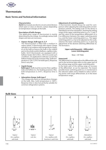
Bulb Sizes<br />
A E P C F<br />
Vapour Vapour Vapour Liquid Adsorption<br />
2m, capillary coil, 0m 2m, capillary with 2m, capillary 2m, capillary<br />
with bulb function C and D 6m with bulb with bulb<br />
A2.5.1/0601/E