Correction Tables for Series HP 90 Valve selection for operating conditions other than +4°C/+38°C and 1 K liquid subcooling: Q n = Q o x K t x K∆p Q n : Nominal valve capacity K t : Correction factor for evaporting and liquid temperature K∆p: Correction factor for pressure drop at valve Q o : Required cooling capacity Liquid Correction Factor K t Temperature Evaporating Temperature entering Valve R 134a R 22 R 404A °C +10 0 -10 -20 +10 0 -10 -20 -30 -40 +10 0 -10 -20 -30 -40 +60 1,33 1,40 1,48 1,56 1,26 1,30 1,33 1,38 1,44 1,50 1,74 1,88 2,06 2,28 2,57 2,95 +55 1,23 1,29 1,36 1,43 1,19 1,22 1,25 1,29 1,34 1,39 1,46 1,55 1,68 1,83 2,01 2,25 +50 1,15 1,20 1,26 1,32 1,12 1,15 1,18 1,21 1,26 1,30 1,26 1,34 1,43 1,54 1,68 1,84 +45 1,08 1,12 1,17 1,22 1,06 1,08 1,11 1,14 1,18 1,23 1,12 1,18 1,26 1,34 1,45 1,57 +40 1,01 1,05 1,10 1,14 1,01 1,03 1,05 1,08 1,12 1,16 1,02 1,07 1,13 1,20 1,28 1,38 +35 0,96 0,99 1,03 1,07 0,96 0,98 1,00 1,03 1,06 1,10 0,93 0,97 1,02 1,08 1,15 1,23 +30 0,91 0,94 0,98 1,01 0,92 0,94 0,96 0,98 1,01 1,04 0,86 0,90 0,94 0,99 1,05 1,11 +25 0,86 0,89 0,92 0,95 0,88 0,89 0,91 0,94 0,96 0,99 0,80 0,83 0,87 0,92 0,97 1,02 +20 0,82 0,85 0,88 0,91 0,84 0,86 0,87 0,90 0,92 0,95 0,75 0,78 0,81 0,85 0,90 0,95 +15 0,78 0,81 0,84 0,86 0,81 0,82 0,84 0,86 0,88 0,91 0,71 0,73 0,76 0,80 0,84 0,88 +10 0,77 0,80 0,82 0,79 0,81 0,82 0,85 0,87 0,69 0,72 0,75 0,79 0,83 +5 0,74 0,76 0,78 0,76 0,78 0,79 0,81 0,83 0,66 0,68 0,71 0,74 0,78 0 0,73 0,75 0,75 0,76 0,78 0,80 0,65 0,68 0,71 0,74 -5 0,70 0,72 0,74 0,74 0,75 0,77 0,62 0,65 0,67 0,70 -10 0,69 0,71 0,73 0,74 0,62 0,64 0,67 Correction Factor K∆p ∆p (bar) 0,10 0,15 0,20 0,25 0,30 0,35 0,40 0,45 0,50 0,55 0,60 0,65 0,70 K∆p 1,87 1,53 1,32 1,18 1,08 1,00 0,94 0,88 0,84 0,80 0,76 0,73 0,71 Liquid Correction Factor K t Temperature Evaporating Temperature entering Valve R 407C R 507 R 410A °C +10 0 -10 -20 +10 0 -10 -20 -30 -40 +10 0 -10 -20 -30 -40 +55 1,28 1,34 1,40 1,48 1,45 1,54 1,65 1,79 1,95 2,16 +50 1,17 1,22 1,27 1,33 1,27 1,34 1,42 1,52 1,64 1,79 1,23 1,26 1,30 1,35 1,40 1,46 +45 1,08 1,12 1,17 1,22 1,13 1,19 1,25 1,33 1,43 1,54 1,12 1,15 1,18 1,22 1,26 1,31 +40 1,01 1,04 1,08 1,13 1,03 1,07 1,13 1,20 1,27 1,36 1,03 1,06 1,08 1,12 1,15 1,20 +35 0,94 0,98 1,01 1,05 0,94 0,98 1,03 1,09 1,15 1,22 0,96 0,98 1,00 1,03 1,06 1,10 +30 0,89 0,92 0,95 0,99 0,88 0,91 0,95 1,00 1,05 1,11 0,90 0,92 0,94 0,96 0,99 1,02 +25 0,84 0,87 0,90 0,93 0,82 0,85 0,88 0,92 0,97 1,02 0,85 0,86 0,88 0,90 0,93 0,96 +20 0,80 0,82 0,85 0,88 0,77 0,79 0,82 0,86 0,90 0,95 0,80 0,81 0,83 0,85 0,87 0,90 +15 0,76 0,78 0,81 0,84 0,72 0,75 0,77 0,81 0,84 0,88 0,76 0,77 0,79 0,81 0,83 0,85 +10 0,75 0,77 0,80 0,70 0,73 0,76 0,79 0,83 0,74 0,75 0,77 0,78 0,81 +5 0,72 0,74 0,76 0,67 0,69 0,71 0,74 0,78 0,70 0,71 0,73 0,75 0,77 0 0,71 0,73 0,65 0,68 0,70 0,73 0,68 0,70 0,71 0,73 -5 0,68 0,70 0,62 0,64 0,66 0,69 0,65 0,67 0,68 0,70 -10 0,67 0,61 0,63 0,65 0,64 0,65 0,67 Correction Factor K∆p ∆p (bar) 0,10 0,15 0,20 0,25 0,30 0,35 0,40 0,45 0,50 0,55 0,60 0,65 0,70 K∆p 1,87 1,53 1,32 1,18 1,08 1,00 0,94 0,88 0,84 0,80 0,76 0,73 0,71 A2.5.1/0601/E
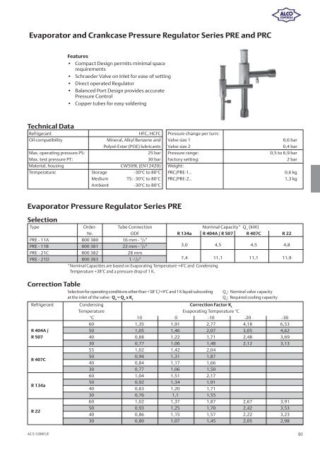
Evaporator and Crankcase Pressure Regulator Series PRE and PRC Technical Data Refrigerant HFC, HCFC Pressure change per turn: Oil compatibility Mineral, Alkyl Benzene and Valve size 1 0,6 bar Correction Table A2.5.1/0601/E Features • Compact Design permits minimal space requirements • Schraeder Valve on Inlet for ease of setting • Direct operated Regulator • Balanced Port Design provides accurate Pressure Control • Copper tubes for easy soldering Polyol-Ester (POE) lubricants Valve size 2 0,4 bar Max. operating pressure PS: 25 bar Pressure range: 0,5 to 6,9 bar Max. test pressure PT: 30 bar Factory setting: 2 bar Material, housing CW509L (EN12420) Weight: Temperature: Storage -30°C to 80°C PRC/PRE-1.. 0,6 kg Medium TS: -30°C to 80°C PRC/PRE-2.. 1,3 kg Ambient -30°C to 80°C Evaporator Pressure Regulator Series PRE Selection Type Order- Tube Connection Nominal Capacity* Q n (kW) Nr. ODF R 134a R 404A / R 507 R 407C R 22 PRE - 11A 800 380 16 mm - 5 /8” PRE - 11B 800 381 22 mm - 7 /8” 3,0 4,5 4,5 4,8 PRE - 21C 800 382 28 mm PRE - 21D 800 383 1 - 1 /8” 7,4 11,1 11,1 11,9 *Nominal Capacities are based on Evaporating Temperature +4°C and Condensing Temperature +38°C and a pressure drop of 1 K. Selection for operating conditions other than +38°C/+4°C and 1 K liquid subcooling at the inlet of the valve: Q n = Q o x K t Refrigerant Condensing Correction Factor K t Temperature Evaporating Temperature °C Q n : Nominal valve capacity Q o : Required cooling capacity °C 10 0 -10 -20 -30 60 1,35 1,91 2,77 4,18 6,53 R 404A / 50 1,05 1,46 2,07 3,05 4,62 R 507 40 0,88 1,22 1,71 2,48 3,69 30 0,77 1,06 1,48 2,12 3,13 55 1,02 1,42 2,04 R 407C 50 0,94 1,31 1,87 40 0,84 1,17 1,66 30 0,77 1,06 1,50 60 1,04 1,51 2,17 R 134a 50 0,92 1,34 1,91 40 0,83 1,20 1,71 30 0,76 1,1 1,55 60 1,02 1,37 1,87 2,67 3,91 R 22 50 0,93 1,25 1,70 2,42 3,53 40 0,86 1,15 1,57 2,22 3,23 30 0,80 1,07 1,45 2,05 2,98 91