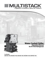
Air Cooled Split Product Data Catalog - Multistack
Air Cooled Split Product Data Catalog - Multistack
Air Cooled Split Product Data Catalog - Multistack

You also want an ePaper? Increase the reach of your titles
YUMPU automatically turns print PDFs into web optimized ePapers that Google loves.
sm<br />
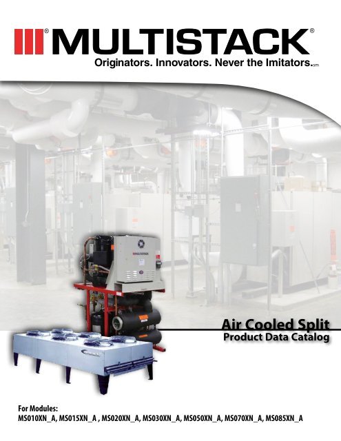
<strong>Air</strong> <strong>Cooled</strong> <strong>Split</strong><br />
<strong>Product</strong> <strong>Data</strong> <strong>Catalog</strong><br />
For Modules:<br />
MS010XN_A, MS015XN_A , MS020XN_A, MS030XN_A, MS050XN_A, MS070XN_A, MS085XN_A
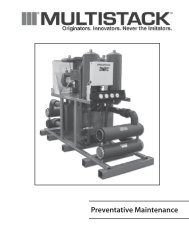
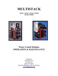
Fuse Box<br />
Control Box<br />
Filter/Driers<br />
Highly Dependable<br />
• Multiple independent systems for built-in standby<br />
• Comprehensive computer monitoring of operations<br />
• Automatic diagnostic recording of fault conditions<br />
• Rotates lead compressor every 24 hours<br />
Simple To Operate<br />
• Large LCD screen displays information in plain English<br />
• Simple keypad provides control of unit operations<br />
Easy To Install<br />
• Compact modules fit through standard doorways and into elevators<br />
• Modules interconnect easily and quickly<br />
• All refrigeration systems are evacuated and shipped with a holding charge<br />
of nitrogen<br />
• Each compressor is charged with oil. (Additional oil may be required<br />
at the time of start-up to accommodate the air cooled condenser and<br />
interconnecting lines.)<br />
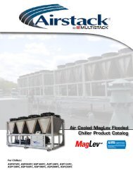
<strong>Air</strong> <strong>Cooled</strong> <strong>Split</strong><br />
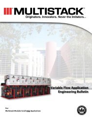
Compressors<br />
3<br />
Fuse Box<br />
Control Box<br />
Bussbar Duct<br />
Liquid Receivers Evaporator Water<br />
Computer Control System<br />
• Operates only the capacity required by the load<br />
• Provides local and remote monitoring control of the chiller<br />
• Operates at peak efficiency at any given load<br />
• Provides operating load profile<br />
Design Flexibility<br />
• Wide array of module combinations<br />
• Install only the capacity required at the time<br />
Simple T o Service<br />
• Does not require unique proprietary training<br />
• Service can often be performed on a convenient, non-emergency basis<br />
• Most components are standard, off the shelf design<br />
Optional<br />
• Vertical discharge and liquid connections available upon request.
<strong>Air</strong> <strong>Cooled</strong> <strong>Split</strong><br />
Performance <strong>Data</strong><br />
SINGLE MODULE<br />
PERFORMANCE DATA<br />
Saturated Discharge Temperature<br />
MS010XN_A 105°F 115°F 125°F<br />
Leaving Chilled Water °F Output Tons KW EER<br />
Output<br />
Tons<br />
KW EER Output Tons KW EER<br />
40° 9.9 9.3 12.8 9.2 10.4 10.6 8.4 11.6 8.7<br />
42° 10.3 9.3 13.3 9.6 10.3 11.2 8.8 11.5 9.2<br />
44° 10.7 9.2 14.0 10.0 10.3 11.7 9.2 11.5 9.6<br />
45° 11.0 9.2 14.3 10.2 10.3 11.9 9.4 11.5 9.8<br />
46° 11.2 9.2 14.6 10.5 10.2 12.4 9.6 11.4 10.1<br />
48° 11.6 9.2 15.1 10.9 10.2 12.8 10.1 11.4 10.6<br />
50° 12.1 9.1 16.0 11.3 10.1 13.4 10.5 11.3 11.2<br />
SINGLE MODULE<br />
PERFORMANCE DATA<br />
Saturated Discharge Temperature<br />
MS015XN_A 105°F 115°F 125°F<br />
Leaving Chilled Water °F Output Tons KW EER<br />
Output<br />
Tons<br />
KW EER Output Tons KW EER<br />
40° 14.4 13.1 13.2 13.5 14.6 11.1 12.6 16.4 9.2<br />
42° 15.0 13.2 13.6 14.1 14.7 11.5 13.1 16.4 9.6<br />
44° 15.6 13.2 14.2 14.7 14.7 12.0 13.7 16.4 10.0<br />
45° 15.9 13.2 14.5 14.9 14.7 12.2 13.9 16.4 10.2<br />
46° 16.2 13.2 14.7 15.2 14.7 12.4 14.2 16.4 10.4<br />
48° 16.9 13.2 15.4 15.8 14.7 12.9 14.8 16.4 10.8<br />
50° 17.6 13.2 16.0 16.5 14.7 13.5 15.4 16.4 11.3<br />
SINGLE MODULE<br />
PERFORMANCE DATA<br />
Saturated Discharge Temperature<br />
MS020XN_A 105°F 115°F 125°F<br />
Leaving Chilled Water °F Output Tons KW EER Output Tons KW EER<br />
Output<br />
Tons<br />
KW EER<br />
40° 20.0 16.8 14.3 18.6 18.9 11.8 17.0 21.4 9.5<br />
42° 20.8 16.8 14.9 19.3 18.9 12.3 17.8 21.4 10.0<br />
44° 21.6 16.8 15.4 20.1 18.9 12.8 18.6 21.4 10.4<br />
45° 22.0 16.9 15.6 20.6 18.9 13.1 19.0 21.4 10.7<br />
46° 22.4 16.9 15.9 21.0 18.9 13.3 19.3 21.4 10.8<br />
48° 23.3 16.9 16.5 21.8 18.9 13.8 20.2 21.4 11.3<br />
50° 24.2 16.9 17.2 22.7 18.9 14.4 21.0 21.4 11.8<br />
SINGLE MODULE<br />
PERFORMANCE DATA<br />
Saturated Discharge Temperature<br />
MS030XN_A 105°F 115°F 125°F<br />
Leaving Chilled<br />
Water °F<br />
Output Tons KW EER Output Tons KW EER Output Tons KW EER<br />
40° 30.0 25.2 14.3 28.1 27.9 12.1 26.1 31.1 10.1<br />
42° 31.1 25.3 14.8 29.2 28.0 12.5 27.1 31.1 10.5<br />
44° 32.3 25.4 15.3 30.4 28.1 13.0 28.2 31.2 10.8<br />
45° 32.9 25.4 15.5 30.9 28.1 13.2 28.8 31.3 11.0<br />
46° 33.6 25.5 15.8 31.5 28.2 13.4 29.3 31.3 11.2<br />
48° 34.8 25.6 16.3 32.7 28.3 13.9 30.5 31.4 11.7<br />
50° 36.1 25.8 16.8 34.0 28.4 14.4 31.7 31.5 12.1<br />
All performance data is based on a 10°F chilled water temperature drop through the evaporator. For total chiller<br />
performance, multiply above outputs (TONS) and input (KW) by the number of modules. For selection procedure see<br />
selection example.<br />
4
<strong>Air</strong> <strong>Cooled</strong> <strong>Split</strong><br />
Performance <strong>Data</strong><br />
SINGLE MODULE<br />
PERFORMANCE DATA<br />
Saturated Discharge Temperature<br />
MS050XN_A 105°F 115°F 125°F<br />
Leaving Chilled<br />
Water °F<br />
Output Tons KW EER Output Tons KW EER Output Tons KW EER<br />
40°F 48.2 40.7 14.2 45.1 45.2 12 41.9 50.4 10<br />
42°F 50.1 40.8 14.7 46.9 45.4 12.4 46.9 45.4 12.4<br />
44°F 52.1 41 15.2 48.8 45.5 12.9 48.8 45.5 12.9<br />
45°F 53.1 41 15.5 49.8 45.5 13.1 49.8 45.5 13.1<br />
46°F 54.1 41.1 15.8 50.7 45.6 13.3 50.7 45.6 13.3<br />
48°F 56.3 41.2 16.4 52.7 45.7 13.8 52.7 45.7 13.8<br />
50°F 58.4 41.4 16.9 54.8 45.8 14.4 54.8 45.8 14.4<br />
SINGLE MODULE<br />
PERFORMANCE DATA<br />
Saturated Discharge Temperature<br />
MS070XN_A 105°F 115°F 125°F<br />
Leaving Chilled<br />
Water °F<br />
Output Tons KW EER Output Tons KW EER Output Tons KW EER<br />
40°F 63.2 52.7 14.4 59.2 58.6 12.1 55.0 65.4 10.1<br />
42°F 65.7 52.9 14.9 61.6 58.8 12.6 57.3 65.5 10.5<br />
44°F 68.2 53.1 15.4 64.0 59.0 13.0 59.6 65.7 10.9<br />
45°F 69.5 53.2 15.7 65.3 59.1 13.3 60.7 65.8 11.1<br />
46°F 70.9 53.4 15.9 66.5 59.2 13.5 61.9 65.9 11.3<br />
48°F 73.6 53.6 16.5 69.1 59.4 14.0 64.3 66.1 11.7<br />
50°F 76.4 53.9 17.0 71.7 59.7 14.4 66.8 66.3 12.1<br />
SINGLE MODULE<br />
PERFORMANCE DATA<br />
Saturated Discharge Temperature<br />
MS085XN_A 105°F 115°F 125°F<br />
Leaving Chilled Water °F Output Tons<br />
40°<br />
42°<br />
44°<br />
45°<br />
46°<br />
48°<br />
50°<br />
KW EER Output Tons KW EER<br />
Output<br />
Tons<br />
KW EER<br />
Call Factory<br />
All performance data is based on a 10°F chilled water temperature drop through the evaporator. For total chiller<br />
performance, multiply above outputs (TONS) and input (KW) by the number of modules. For selection procedure see<br />
selection example.<br />
5
Pressure Drop-Feet of Water<br />
50<br />
40<br />
30<br />
20<br />
10<br />
9<br />
8<br />
7<br />
6<br />
5<br />
4<br />
3<br />
2<br />
A MS010XN_A<br />
B MS015XN_A<br />
C MS020XN_A<br />
D MS030XN_A<br />
20<br />
30<br />
Figure 2. Water Pressure Drop<br />
40<br />
E MS050XN_A<br />
F MS070XN_A<br />
G MS085XN_A<br />
50<br />
60<br />
70<br />
80<br />
90<br />
100<br />
200<br />
Water Flow GMP Per Module<br />
<strong>Air</strong> <strong>Cooled</strong> <strong>Split</strong><br />
Pressure Drop Chart<br />
300<br />
Performance <strong>Data</strong><br />
400<br />
500<br />
600<br />
6<br />
Figure 3. Ethylene Glycol Adjustment Factor<br />
Adjustment Factor<br />
1.60<br />
1.50<br />
1.40<br />
1.30<br />
1.20<br />
1.10<br />
1.00<br />
0.90<br />
0.80<br />
1.70<br />
1.60<br />
1.50<br />
1.40<br />
1.30<br />
1.20<br />
1.10<br />
1.00<br />
.90<br />
.80<br />
Pressure Drop<br />
10% 20% 30% 40% 50%<br />
Figure 4. Propylene Glycol Adjustment Factor<br />
Adjustment Factor<br />
% Ethylene Glycol<br />
Pressure Drop<br />
GPM<br />
GPM<br />
KW<br />
KW<br />
Capacity<br />
Capacity<br />
10% 20% 30% 40% 50%<br />
% Propylene Glycol
<strong>Air</strong> <strong>Cooled</strong> <strong>Split</strong><br />
Chiller Drawing<br />
Performance <strong>Data</strong><br />
7
<strong>Air</strong> <strong>Cooled</strong> <strong>Split</strong><br />
Piping Schematic<br />
8
<strong>Air</strong> <strong>Cooled</strong> <strong>Split</strong><br />
Piping Information<br />
Refrigeration Components Installed in Standard Unit<br />
The following components, normally required in an air cooled split system, are factory installed and shipped as part of the standard <strong>Multistack</strong> module.<br />
• Liquid line solenoid valves<br />
• Check valves<br />
• Liquid line filter/driers<br />
• Liquid line sight glass<br />
• Refrigerant receiver tanks with pressure relief valves and manual shut-off valves. Standard receiver size 50 lbs. (Charge depends on size and application.<br />
Alternate receivers with pressure relief valves may be required after consulting AIRSTACK.)<br />
<strong>Air</strong> <strong>Cooled</strong> Condenser<br />
The air cooled condenser can be purchased directly from a manufacturer by the customer, or as a convenience, <strong>Multistack</strong> will purchase and supply the<br />
condenser. <strong>Multistack</strong> recommends that the air cooled condenser include:<br />
• Separate condenser circuit for each compressor*<br />
• Condenser fans are controlled by head pressure.<br />
• Flooded condenser head pressure control on each circuit for operation at ambient temperatures down to -20°F.<br />
• 3 ph/60 Hz power voltage compatible with chiller and 24VAC control voltage<br />
• Additional oil may have to be added to the system at time of start-up to accommodate the air cooled condenser and interconnecting lines.<br />
•To determine the total HEAT OF REJECTION (THR) for selecting the condenser, use:<br />
HR/Module (MBH) = 12 [TONS + 0.285 (KW)]<br />
THR (MBH) = (No. of Modules) (HR/Module)<br />
*CAUTION: Each Module has two independent refrigeration circuits. A separate condenser circuit is required for each refrigeration circuit.<br />
Interconnecting Refrigerant Piping Between Chiller and Condenser<br />
The interconnecting piping is supplied by others and good engineering practices should be used in sloping and trapping the lines. Recommend line sizes for<br />
use with specific AIRSTACK modules are:<br />
LIQUID LINE SIZES AIR COOLED<br />
MODEL Liquid 50’ Liquid 75' Liquid 100' Liquid 125' Liquid 150’ PSI drop<br />
MS010XN_A<br />
MS015XN_A 5/8” 5/8” 5/8” 5/8” 5/8” 0.5 - 5.0<br />
MS020XN_A 3/4" 3/4" 3/4" 3/4" 3/4” 0.5 - 3.5<br />
MS030XN_A 7/8” 7/8" 7/8" 7/8" 7/8” 0.5 - 3.0<br />
MS050XN_A 1 1/8” 1 1/8” 1 1/8” 1 1/8” 1 1/8” 0.5 - 2.5<br />
MS070XN_A 1 1/8” 1 1/8” 1 1/8” 1 1/8” 1 1/8” 0.5 - 2.5<br />
MS085XN_A<br />
DISCHARGE LINE SIZES AIR COOLED<br />
MODEL Disch 50' Disch 75' Disch 100' Disch 125' Disch 150’ PSI drop<br />
MS010XN_A<br />
MS015XN_A 7/8” 1 1/8” 1 1/8” 1 1/8” 1 1/8” 2.0 - 4.0<br />
MS020XN_A 1 1/8” 1 1/8” 1 1/8” 1 3/8" 1 3/8” 2.0 - 4.0<br />
MS030XN_A 1 1/8” 1 3/8" 1 3/8” 1 3/8" 1 3/8” 2.0 - 4.5<br />
MS050XN_A 1 3/8” 1 5/8" 1 5/8" 1 5/8" 1 5/8” 3.5 - 5.0<br />
MS070XN_A 1 5/8” 1 5/8” 1 5/8” 2 1/8” 2 1/8” 2.0 - 6.0<br />
MS085XN_A<br />
9
<strong>Air</strong> <strong>Cooled</strong> <strong>Split</strong><br />
General <strong>Data</strong> Table<br />
MODEL MS010XN_A MS015XN_A MS020XN_A MS030XN_A<br />
Compressor Type Scroll Scroll Scroll Scroll<br />
Weight (lbs each) 89 135 160 227<br />
Normal Capacity (total) 10 15 20 30<br />
Quantity 2 2 2 2<br />
Oil Change (pints) 3.5 6.9 7 11.5<br />
Evaporator Brazed Plate Brazed Plate Brazed Plate Brazed Plate<br />
Weight (lbs each) 51.7 51.7 51.7 51.7<br />
Water Storage (gallons each) 2.42 2.42 2.42 2.42<br />
Quantity 2 2 2 2<br />
Header System (gallons) 5.5 5.5 5.5 5.5<br />
Refrigerant Type 410 A 410 A 410 A 410 A<br />
Refrigerant Charge (lbs/circuit) 6.5 6.5 8 10<br />
Number of Circuits 2 2 2 2<br />
Operating Weight (lbs) 1070 1120 1150 1300<br />
Shipping Weight (lbs) 1020 1065 1100 1250<br />
MODEL MS050XN_A MS070XN_A MS085XN_A<br />
Compressor Type Scroll Scroll Scroll<br />
Weight (lbs each) 268 407<br />
Normal Capacity (each) 50 70 85<br />
Quantity 2 2 2<br />
Oil Change (pints) 14 12.5<br />
Evaporator Brazed Plate Brazed Plate Brazed Plate<br />
Weight (lbs each) 90.25 205<br />
Water Storage (gallons each) 2.164 5.20<br />
Quantity 2 1 2<br />
Header System (gallons) 5.5 7<br />
Refrigerant Type 410 A 410 A 410 A<br />
Refrigerant Charge (lbs/circuit) 13 20<br />
Number of Circuits 2 2 2<br />
Operating Weight (lbs) 1500 2050<br />
Shipping Weight (lbs) 1475 1750<br />
10
System Wire & Fuse Sizing Specifications<br />
(Applicable codes may require different wire sizing)<br />
1. Compressor Rated Load Amps (RLA) and Locked Rotor Amps (LRA)<br />
<strong>Data</strong>: RLA/LRA<br />
VOLTAGE 208 230 460 575<br />
25T Scroll 81/605* 73/605* 36.5/272* 29/215*<br />
25T Bristol 86/400* 78/400* 39/200* 32/160*<br />
15T Scroll 55/340* 56/340* 26/173* 21/132*<br />
10T Scroll 35/239* 31.5/239* 15.5/125* 12/80*<br />
*Per Compressor<br />
2. Wiring Sizing: Minimum Circuit Ampacity (MCA)<br />
MCA = (1.25 x RLA1*) + RLA2 + RLA3…<br />
MCA<br />
3 Conductors<br />
1 Conduit<br />
6 Conductors<br />
2 Conduit<br />
508 — —<br />
656 — —<br />
854 — —<br />
100 3 —<br />
115 2 —<br />
130 1 —<br />
150 1/0 —<br />
175 2/0 —<br />
200 3/0 —<br />
230 4/0 —<br />
255 250 MCM —<br />
285 300 MCM 1/0<br />
300 — 2/0<br />
350 — 3/0<br />
400 — 4/0<br />
460 — 4/0<br />
500 — 250 MCM<br />
3. Fuse Sizing: Maximum Fuse (MF),Type RK5 Fuse<br />
MF = (2.25 x RLA1*) + RLA2 + RLA3…..<br />
Where the MF does not equal a standard size fuse, the next larger size<br />
should be used.<br />
4. NOTES:<br />
A. Compressor Related Load Amps (RLA) and Locked Rotor Amps<br />
(LRA) are based on 125°F Saturated CondensingTemperature.<br />
B. *RLA1 = RLA of the largest compressor in the system.<br />
RLA2 & RLA3 = RLA of the other compressors in the system.<br />
C. The total system Minimum Circuit Ampacity (MCA) shall not<br />
exceed 500A.<br />
D. Wire sizing is based on the Nat. Elect. Code (NEC) rating for 75°C<br />
copper wire, with 3 wires per conduit.<br />
E. Wiring distance from branch circuit shall not exceed 100 ft.<br />
<strong>Air</strong> <strong>Cooled</strong> <strong>Split</strong><br />
Electrical Information<br />
11<br />
External Input/Output Connections<br />
Inputs<br />
EX1 Close CircuitTo Operate: OpenTo Stop. Manual Reset Required.<br />
EX2 Close CircuitTo Operate: OpenTo Stop. Auto Reset.<br />
Remote Start/Stop<br />
EX3 Close CircuitTo Operate: OpenTo Stop. Manual Reset Required.<br />
EX4 Close CircuitTo Operate: OpenTo Stop. Auto Reset.<br />
CF Condenser Fan Starter Interlock.<br />
FS2 ChilledWater Flow Switch. (Or Optional Pressure Differential Switch)<br />
MS2 ChilledWater Pump Starter Interlock.<br />
TC1 AmbientTemperatureThermostat.<br />
(Required for condenser without low ambient provisions.)<br />
Outputs<br />
CFR Condenser Fan Relay. (24VAC, 5VA)<br />
CAR Customer Alarm Relay (24VAC, 5VA)<br />
Note: Interlock wiring to be 16 AWG minimum and field supplied by<br />
others. External relays, contractors and flow switches supplied by others.
<strong>Air</strong> <strong>Cooled</strong> <strong>Split</strong><br />
Controller Information<br />
ENT. CHILLED WATER TEMP. FAN OPERATION<br />
LVG. CHILLED WATER TEMP.<br />
VERIFY CHILLED WATER FLOW<br />
CUSTOMER INTERLOCKS<br />
MASTER CONTROL AND DISPLAY<br />
(Can stage a maximum of 12 modules)<br />
FAULT NOTIFICATION<br />
MODULE SENSOR PANEL<br />
DATA FROM<br />
REFRIGERATION SYSTEM“A”<br />
COMP. MOTOR<br />
PROTECTION<br />
HP HP<br />
LP LP<br />
DATA FROM<br />
REFRIGERATION SYSTEM“B”<br />
COMP. MOTOR<br />
PROTECTION<br />
SUCTIONTEMPERATURE SUCTIONTEMPERATURE<br />
LEAVING CHILLED<br />
WATERTEMP.<br />
CONTROL PANEL SYSTEM“A”<br />
COMPRESSOR CONTACTOR<br />
LEAVING CHILLED<br />
WATERTEMP.<br />
CONTROL PANEL SYSTEM“B”<br />
COMPRESSOR CONTACTOR<br />
12<br />
REMOTE PC<br />
OPTIONAL<br />
RS-232<br />
SERIAL PORT CONNECTION TO REMOTE PC,<br />
MODEM, BUILDING MANAGEMENT<br />
SYSTEMS, OR<br />
BACnet® PORTAL.<br />
IDENTICAL<br />
SENSOR PANELS MODULE IN<br />
CHILLER
<strong>Air</strong> <strong>Cooled</strong> <strong>Split</strong><br />
Mechanical Spec<br />
General<br />
Modules are ETL listed in accordance with UL standard 1995 and are CSA certified per standard C22.2 #236.<br />
Modules ship wired, charged with oil, and contain a holding charge of dry nitrogen.<br />
Compressors, heat exchangers, piping and controls are mounted on a heavy gauge steel frame. Electrical controls, contactors, and relays for each module,<br />
are mounted within that module.<br />
Factory Mounted Refrigerant Components<br />
Refrigerant receiver tanks with pressure relief valves and shut-off valves, liquid line solenoid valves, check valves, liquid line filter driers and liquid line sight<br />
glasses are factory mounted in each module.<br />
Chilled Water Mains<br />
Each module includes supply and return mains for the chilled water. Grooved end connections are provided for interconnection to 6”US standard (6.625”<br />
outside diameter) customer piping with victaulic type couplings. Standard units include 30 mesh in-line strainers in the evaporator supply headers.<br />
Evaporators<br />
Each evaporator is a brazed plate heat exchanger constructed of 316 stainless steel; designed, tested and stamped in accordance with ASME code for a 360<br />
psig working pressure.<br />
<strong>Air</strong> <strong>Cooled</strong> Condensers<br />
Condensers may be supplied by others, or special ordered by <strong>Multistack</strong>. <strong>Multistack</strong>’s special ordered condensers come factory assembled.The condenser<br />
coil is divided into individual refrigerant circuits, each sized for its own specific application. Each circuit comes with its own inlet and outlet connections,<br />
individually labeled.<br />
Compressors<br />
Each module contains two separate refrigeration systems.The hermetic compressor in each system is mounted to the frame with rubber-in-shear isolators.<br />
Each system also includes high discharge pressure and low suction pressure cutouts.<br />
Central Control System<br />
Scheduling of the various compressors is performed by the microprocessor control. Compressors operating schedules are sequenced every 24 hours to assure<br />
distribution of run time.This microprocessor monitors the following on each refrigeration system:<br />
• Discharge pressure cut-out<br />
• Suction pressure cut-out<br />
• Compressor motor protector<br />
• Suction temperature<br />
• Evaporator entering and leaving chilled water temperature<br />
A fault condition from these controls or sensors will cause a shutdown of that compressor with the transfer of load requirements to another available<br />
compressor.When a fault occurs, the microprocessor records the reading of conditions at the time and stores the data for recall by operating personnel.This<br />
information can be recalled using the keys and displayed on the LCD screen. A running history of the fault occurrence conditions is maintained (up to the<br />
last 20 occurrences) should it be required for trouble shooting.<br />
Individual monitoring of leaving chilled water temperature from each refrigeration system is designed to protect against freeze-up.<br />
The control system monitors entering and leaving chilled water temperatures to determine system load and selects the number of compressors required.<br />
Response time and set points are adjustable.<br />
Options<br />
Options are available upon request.<br />
13
Environmentally Friendly Refrigerants<br />
R-410A<br />
Refrigerant R-410A is widely available, safe, and an environmentally friendly refrigerant. R-410A is available in virtually all <strong>Multistack</strong> systems making hot water up<br />
to 140°F. Good environmental choices!<br />
Environmental Focus<br />
In addition to providing products to deliver reliable comfort and low operating cost, <strong>Multistack</strong>’s products can also reduce your environmental footprint. We are<br />
committed to developing and manufacturing cooling and heating products that can reduce fossil fuel consumption and operate on the refrigerants designed to<br />
protect the environment. <strong>Air</strong> <strong>Cooled</strong> <strong>Split</strong> Modules and efficiency improvements across our product line are the result of this focus.<br />
Originators…<br />
<strong>Multistack</strong> invented the modular water chiller. It started with a radically simple idea: chiller modules that could be brought into the equipment room one at a time,<br />
through standard doorways and down elevators, to form a fully integrated chiller system.The idea launched a revolution and transformed <strong>Multistack</strong> into a leader in<br />
the commercial water-chiller industry.<br />
Innovators…<br />
<strong>Multistack</strong> perfected the modular chiller and leads the industry in innovative and environmentally friendly modular solutions. Since founding in the late 1980s,<br />
<strong>Multistack</strong> has engineered, manufactured, and distributed an impressive array of modular air conditioning firsts: the first on-board strainer, the first modular<br />
automatic blow-down device, the first modular chiller for variable flow, the first modular chiller-heater (heat pump), the first modular heat-recovery chiller, the first<br />
modular air-to-water heat pump, the first modular chiller to utilize MagLev compressor technology, and the first modular chiller to utilize R-410A.<br />
Never the Imitators…<br />
<strong>Multistack</strong> sets the standard in the industry for superior customer service, fast and on time shipment, superior product quality, and new product development. Our<br />
pioneering leadership in environmental issues is well documented. If you want the best, be sure to specify the original – <strong>Multistack</strong>®.<br />
1065 Maple Avenue P.O. Box 510 Sparta, WI 54656<br />
Phone 608-366-2400 • Fax 608-366-2450<br />
www.multistack.com<br />
sm<br />
F1131011