IntelliTuner Automatic Antenna Tuner
IntelliTuner Automatic Antenna Tuner
IntelliTuner Automatic Antenna Tuner

Create successful ePaper yourself
Turn your PDF publications into a flip-book with our unique Google optimized e-Paper software.
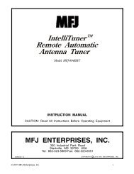
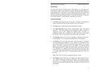
VERSION 1A<br />
TM<br />
<strong>Intelli<strong>Tuner</strong></strong><br />
<strong>Automatic</strong> <strong>Antenna</strong> <strong>Tuner</strong><br />
Model MFJ-993B<br />
INSTRUCTION MANUAL<br />
CAUTION: Read All Instructions Before Operating Equipment<br />
MFJ ENTERPRISES, INC.<br />
300 Industrial Park Road<br />
Starkville, MS 39759 USA<br />
Tel: 662-323-5869 Fax: 662-323-6551<br />
COPYRIGHT C 2005 MFJ ENTERPRISES, INC.
MFJ-993B <strong>Intelli<strong>Tuner</strong></strong> <strong>Automatic</strong> <strong>Antenna</strong> <strong>Tuner</strong> Instruction Manual<br />
© 2003-2005 MFJ Enterprises, Inc.<br />
Contents<br />
THE BASICS<br />
Introduction...................................................................................................................................... 1<br />
Features............................................................................................................................................ 2<br />
Specifications................................................................................................................................... 2<br />
Fast Start .......................................................................................................................................... 3<br />
Front Panel....................................................................................................................................... 4<br />
SWR/Wattmeter.................................................................................................................. 4<br />
LCD Display....................................................................................................................... 4<br />
LCD Contrast Control......................................................................................................... 4<br />
ANT Button ........................................................................................................................ 4<br />
MODE Button.....................................................................................................................4<br />
C-UP and C-DN Buttons .................................................................................................... 4<br />
L-UP and L-DN Buttons..................................................................................................... 5<br />
AUTO Button .....................................................................................................................5<br />
TUNE Button...................................................................................................................... 5<br />
VOL Control....................................................................................................................... 5<br />
POWER Button................................................................................................................... 5<br />
Back Panel ....................................................................................................................................... 7<br />
Power .................................................................................................................................. 7<br />
Remote Port ........................................................................................................................ 7<br />
Radio Interface.................................................................................................................... 7<br />
Transmitter.......................................................................................................................... 8<br />
Ground ................................................................................................................................ 8<br />
Balanced Line ..................................................................................................................... 9<br />
Wire .................................................................................................................................... 9<br />
<strong>Antenna</strong> 1............................................................................................................................ 9<br />
<strong>Antenna</strong> 2............................................................................................................................ 9<br />
Installation ....................................................................................................................................... 9<br />
SWR/Wattmeter............................................................................................................................. 10<br />
THE MENUS<br />
Main Mode Menus......................................................................................................................... 11<br />
Digital Wattmeter Menu ................................................................................................... 11<br />
Power Bar Meter Menu..................................................................................................... 11<br />
SWR Bar Meter Menu ...................................................................................................... 12<br />
L-Network Menu .............................................................................................................. 12<br />
<strong>Tuner</strong> Indicators............................................................................................................................. 13<br />
<strong>Antenna</strong>............................................................................................................................. 13<br />
IntelliTune......................................................................................................................... 13<br />
Memory............................................................................................................................. 13<br />
Power Level ...................................................................................................................... 13<br />
LC Limit ........................................................................................................................... 14<br />
Meter Range...................................................................................................................... 14<br />
i
MFJ-993B <strong>Intelli<strong>Tuner</strong></strong> <strong>Automatic</strong> <strong>Antenna</strong> <strong>Tuner</strong> Instruction Manual<br />
ii<br />
Auto/Semi ......................................................................................................................... 14<br />
StickyTune........................................................................................................................ 14<br />
Setup Mode Menus ........................................................................................................................ 15<br />
Power Level Menu............................................................................................................ 15<br />
Target SWR Menu ............................................................................................................ 15<br />
Auto Tune SWR Menu ..................................................................................................... 15<br />
Meter Range Menu ........................................................................................................... 16<br />
Peak Hold Menu ............................................................................................................... 16<br />
Memory Menu .................................................................................................................. 16<br />
IntelliTune Menu .............................................................................................................. 17<br />
SWR Beep Menu .............................................................................................................. 17<br />
Beep Menu........................................................................................................................ 17<br />
Refresh Menu.................................................................................................................... 17<br />
LC Limit Menu ................................................................................................................. 18<br />
OPERATION<br />
Manual Tuning............................................................................................................................... 18<br />
Meter Codes and Audible Beeps.................................................................................................... 19<br />
Foldback Circuit ............................................................................................................................ 20<br />
Grounding Hints ............................................................................................................................ 21<br />
<strong>Antenna</strong> System Hints.................................................................................................................... 21<br />
Location ............................................................................................................................ 21<br />
Matching Problems ........................................................................................................... 21<br />
APPENDICES<br />
Resetting the <strong>Tuner</strong>........................................................................................................................ 23<br />
Factory Defaults................................................................................................................ 23<br />
Delete <strong>Antenna</strong> Memory................................................................................................... 24<br />
Total Reset ........................................................................................................................ 24<br />
Self Test ......................................................................................................................................... 24<br />
Power Down Circuit Test............................................................................................................... 25<br />
Relay Test ...................................................................................................................................... 26<br />
Firmware Version Number via Meter............................................................................................ 26<br />
Setting the Speaker Volume........................................................................................................... 26<br />
Wattmeter Calibration.................................................................................................................... 27<br />
SWR Bridge Calibration................................................................................................................ 27<br />
Frequency Counter Calibration...................................................................................................... 28<br />
In Case of Difficulty ...................................................................................................................... 29<br />
Technical Assistance...................................................................................................................... 29<br />
List of Accessories......................................................................................................................... 29<br />
Circuit Block Diagram................................................................................................................... 30<br />
© 2003-2005 MFJ Enterprises, Inc.
MFJ-993B <strong>Intelli<strong>Tuner</strong></strong> <strong>Automatic</strong> <strong>Antenna</strong> <strong>Tuner</strong> Instruction Manual<br />
FIGURES<br />
Figure 1. Installation Block Diagram.............................................................................................. 3<br />
Figure 2. MFJ-993B Front Panel .................................................................................................... 4<br />
Figure 3. Mode Button Flow Chart and Button Action .................................................................. 6<br />
Figure 4. MFJ-993B Back Panel..................................................................................................... 7<br />
Figure 5. Alinco Interface Cable..................................................................................................... 8<br />
Figure 6. Icom Interface Cable ....................................................................................................... 8<br />
Figure 7. SWR/Wattmeter ............................................................................................................ 10<br />
Figure 8. Power Bar Meter (High Range)..................................................................................... 12<br />
Figure 9. Power Bar Meter (Low Range) ..................................................................................... 12<br />
Figure 10. SWR Bar Meter ........................................................................................................... 12<br />
Figure 11. Main Mode Menus Display ......................................................................................... 13<br />
Figure 12. <strong>Tuner</strong> Indicators........................................................................................................... 14<br />
Figure 13. Power-On Operations .................................................................................................. 23<br />
Figure 14. MFJ-993B Circuit Block Diagram .............................................................................. 30<br />
TABLES<br />
Table 1. Memory Resolution ........................................................................................................ 16<br />
Table 2. Meter Needle Stationary Codes ...................................................................................... 19<br />
Table 3. Meter Needle Bounce Codes .......................................................................................... 20<br />
Table 4. Failure Messages............................................................................................................. 25<br />
© 2003-2005 MFJ Enterprises, Inc.<br />
iii
MFJ-993B <strong>Intelli<strong>Tuner</strong></strong> <strong>Automatic</strong> <strong>Antenna</strong> <strong>Tuner</strong> Instruction Manual<br />
iv<br />
THIS PAGE IS LEFT BLANK INTENTIONALLY<br />
© 2003-2005 MFJ Enterprises, Inc.
MFJ-993B <strong>Intelli<strong>Tuner</strong></strong> <strong>Automatic</strong> <strong>Antenna</strong> <strong>Tuner</strong> Instruction Manual<br />
Introduction<br />
© 2003-2005 MFJ Enterprises, Inc.<br />
The Basics<br />
The MFJ-993B <strong>Intelli<strong>Tuner</strong></strong> TM lets you rapidly tune any antenna automatically: balanced, unbalanced, or<br />
single-wire. The MFJ-993B is a comprehensive automatic antenna tuning center with SWR/wattmeter,<br />
antenna switch for two antennas, and a 4:1 current balun for balanced lines.<br />
MFJ's exclusive InstantRecall TM , IntelliTune TM and AdaptiveSearch TM algorithms give you fast automatic<br />
tuning with more than 20,000 non-volatile Virtual<strong>Antenna</strong> TM memories. Each of the two antennas has<br />
four banks of memory; each memory bank has over 2500 non-volatile memories for tuner settings.<br />
The tuner includes a highly efficient switching L-network with wide matching capability, 1.8 to 30 MHz<br />
coverage, cross-needle power meters, backlight LCD display, a port for an accessory remote control, a<br />
radio interface port, and heavy-duty 16 amp/1000 volt relays. It is rated at 300 watts to match 6 to 1600<br />
ohms antennas (SWR up to 32:1) or 150 watts to match wider range of 6 to 3200 ohms (SWR up to 64:1).<br />
A maximum of 256 values of inductance and 256 values of capacitance are available. With the<br />
capacitance switched between the input and output side, this provides a total of 131,072 L/C tuning<br />
combinations. The nominal tuning ranges are 0 to 24 μH and 0 to 3900 pF.<br />
All MFJ <strong>Intelli<strong>Tuner</strong></strong>s TM learn and remember. When you transmit, they automatically adjust for minimum<br />
SWR and remember the frequency and tuner settings, safely stored in non-volatile memory. The next<br />
time you operate on that frequency (or close to it) and antenna, these tuner settings are instantly restored<br />
and you’re ready to operate in milliseconds. Each of two antenna selections has four banks of memory,<br />
which can learn and remember more than 2500 frequencies and tuner settings per bank.<br />
When you key your transmitter, MFJ’s InstantRecall TM checks its memory to see if you have operated<br />
that frequency before. If so, tuning is instantaneous and you’re ready to operate. If not, MFJ’s<br />
IntelliTune TM algorithm (based on MFJ’s famous SWR Analyzer technology) kicks in. It measures the<br />
complex impedance of your antenna. Next, it calculates the components it needs and instantly snaps them<br />
in. Finally, it fine-tunes to minimize SWR, and you’re ready to operate--all in a fraction of a second.<br />
If the antenna impedance is not within the tuner’s measurement range, MFJ’s AdaptiveSearch TM<br />
algorithm goes into action. Frequency is measured and relevant components values are determined. Only<br />
those values are searched for fast tuning. If it still cannot find a match, the search is performed again<br />
using a different search pattern.<br />
The target SWR can be set at 1.0 through 2.0. The minimum power to tune is approximately two watts.<br />
You can manually tune where you can’t transmit (for listening out of ham bands).<br />
All MFJ’s <strong>Intelli<strong>Tuner</strong></strong>s TM support radio tuner interfaces that are compatible with Alinco EDX-2 tuner,<br />
Icom AH-3 and AH-4 tuners, Kenwood AT-300 tuner, Yaesu FC-30 tuner, and certain Yaesu radios with<br />
CAT system. Optional interface cables MFJ-5124A (for Alinco), MFJ-5124I (for Icom), MFJ-5124K (for<br />
Kenwood), MFJ-5124Y and MFJ-5124Y2 (for Yaesu) are available from MFJ Enterprises, Inc. The<br />
optional MFJ-993RC Remote Control provides most tuner controls, allowing convenient remote locating<br />
of the tuner itself.<br />
The tuners enter a “sleep” mode when idle and when no transmit signal is present, turning off the<br />
microprocessor clock to avoid the generation of spurious signals.<br />
1
MFJ-993B <strong>Intelli<strong>Tuner</strong></strong> <strong>Automatic</strong> <strong>Antenna</strong> <strong>Tuner</strong> Instruction Manual<br />
Features<br />
• <strong>Automatic</strong>ally matches antennas with impedances of 6 to 1600 ohms or 6 to 3200 ohms<br />
• Handles 300 watts (match 6 to 1600 ohms) or 150 watts (match 6 to 3200 ohms)<br />
• Tune in less than 15 seconds, usually less than 5 seconds<br />
• Over 20,000 non-volatile memories for tuner settings<br />
• Four memory banks per antenna with over 2500 memories per bank<br />
• Highly efficient switching L-network matching circuit<br />
• 1.8 to 30 MHz continuous frequency coverage<br />
• Adjustable target SWR 1.0 to 2.0<br />
• Adjustable SWR threshold 0.5 to 1.5<br />
• Lighted cross-needle SWR/wattmeter with high, low, and auto range options<br />
• Multifunction backlit LCD display with contrast control<br />
• Numeric readings for SWR, forward and reflected power<br />
• Bar meters for SWR, forward and reflected power with range options<br />
• Audio SWR meter with volume control<br />
• Built-in frequency counter<br />
• Two SO-239 coax fed antenna connectors<br />
• Connector for random wire or single wire antennas<br />
• Built-in 4:1 current balun for balanced line antennas<br />
• Optional remote control<br />
• Optional radio interface for compatible radios<br />
Specifications<br />
• Impedance matching range: 6 to 1600 ohms (300 watts) or 6 to 3200 ohms (150 watts)<br />
• SWR matching range: up to 8:1 for < 50 ohms and up to 32:1 for > 50 ohms (300 watts)<br />
up to 8:1 for < 50 ohms and up to 64:1 for > 50 ohms (150 watts)<br />
• Minimum power for tuning: 2 watts<br />
• Maximum power while tuning: 100 watts with foldback, 20 watts without foldback<br />
• RF power limit: 300 watts SSB/CW<br />
• Frequency range: 1.8 to 30 MHz continuous coverage<br />
• Frequency counter accuracy: ±1 kHz across HF bands<br />
• Frequency counter range: up to 50 MHz<br />
• Capacitance range: 0 to 3908 pF nominal (256 values)<br />
• Inductance range: 0 to 24.86 μH nominal (256 values)<br />
• Relay rating: 16 amp 1000 volts<br />
• Relay electrical life: 100,000 operations<br />
• Relay mechanical life: 10 million operations<br />
• Memory endurance: 1 million erase/write cycles<br />
• Memory data retention: > 200 years<br />
• Power requirements: 12 - 15 volts DC, 2.1 × 5.5 mm coaxial plug, center pin positive<br />
• Current consumption: 1 amp or less<br />
• Dimensions (approx.): 10.1 × 2.8 × 9.2 in. (257 × 71 × 234 mm) (width/height/depth)<br />
not including connectors<br />
• Weight (approx.): 3.9 lb (1.77 kg)<br />
† Specifications and design are subject to change without notice.<br />
2<br />
© 2003-2005 MFJ Enterprises, Inc.
MFJ-993B <strong>Intelli<strong>Tuner</strong></strong> <strong>Automatic</strong> <strong>Antenna</strong> <strong>Tuner</strong> Instruction Manual<br />
Fast Start<br />
© 2003-2005 MFJ Enterprises, Inc.<br />
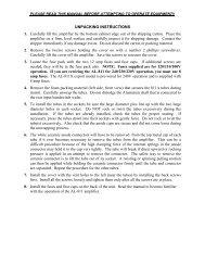
WARNING<br />
● Never operate the tuner with its cover removed. Contact with the components inside the<br />
tuner while transmitting will result in painful RF burns.<br />
● Locate the tuner so that the rear terminals are not accessible during operation. The single<br />
wire and balanced line connection may have high voltage while transmitting.<br />
● Disconnect all antennas from the tuner during lightning storms.<br />
● Always tune with low power (about 10 watts). Apply maximum power only after tuning up.<br />
● Never exceed tuner specifications.<br />
● Do not transmit with a high SWR for extended periods of time.<br />
1. Connect the MFJ-993B to a 12-15 VDC voltage source capable of supplying at least 1 amp.<br />
2. Connect your transmitter to the TRANSMITTER connector using a 50-ohm coaxial cable.<br />
3. Connect your coax-fed antenna to the ANTENNA 1 connector using a 50-ohm coaxial cable, or<br />
connect your random wire to the WIRE binding post, or connect your balanced line antenna to the<br />
BALANCED LINE binding posts and connect a jumper between the other two posts as indicated.<br />
4. Connect your ground connection to the GROUND post.<br />
5. Press the [POWER] button to turn on the MFJ-993B tuner. Place the [ANT] button in the out<br />
position to select antenna 1. Press the [AUTO] button in to select semi-automatic mode.<br />
6. Key your transmitter to output a carrier of 10 watts CW, FM or AM.<br />
7. Press and hold the [TUNE] button on the MFJ-993B for one second to start the automatic tuning<br />
process. When completed, check to ensure an SWR of 2.0 or less before increasing RF power.<br />
8. You are ready to transmit.<br />
Note: During the automatic tuning process, the tuner will make some noise. These are the relays<br />
switching at a very fast pace and it is normal operation. Do not be alarmed.<br />
Note: When the tuner power is OFF, the tuner is in bypass mode and RF from the transmitter goes<br />
directly to the antenna (ANTENNA 1) with no matching. When the tuner power is ON,<br />
pressing [C-DN] and [L-DN] simultaneously or pressing [TUNE] quickly places the tuner in<br />
bypass mode (zero inductance and zero capacitance) and indicates by the reflected needle<br />
bouncing to 20 watts.<br />
Transmitter MFJ-993B<br />
50-ohm Coax<br />
RF Ground 12 VDC<br />
<strong>Antenna</strong> 1<br />
Figure 1. Installation Block Diagram.<br />
<strong>Antenna</strong> 2<br />
3
MFJ-993B <strong>Intelli<strong>Tuner</strong></strong> <strong>Automatic</strong> <strong>Antenna</strong> <strong>Tuner</strong> Instruction Manual<br />
Front Panel<br />
4<br />
0<br />
60<br />
40<br />
8<br />
20<br />
5.0<br />
10 30 50<br />
3.0 2.0<br />
100 200 300<br />
10<br />
5<br />
1.5 1.2<br />
400-3083 1<br />
MODEL<br />
MFJ-993B<br />
0<br />
Hi x1<br />
Lo x.1<br />
SWR<br />
14.100MHz 1.1<br />
FWD=100 REF=0.5<br />
SWR 1 1.2 1.5 2 3<br />
PWR 0 25 50 75 100 300<br />
MFJ <strong>Intelli<strong>Tuner</strong></strong> TM<br />
AUTOMATIC ANTENNA TUNER<br />
Figure 2. MFJ-993B Front Panel.<br />
ANT C-UP L-UP AUTO POWER<br />
Z<br />
MODE C-DN L-DN TUNE<br />
LCD VOL<br />
BYPASS<br />
Dual Power Level<br />
300/150 Watts<br />
• SWR/Wattmeter: The cross-needle meter measures forward power, reflected power, and SWR. It<br />
operates whenever the tuner is power on. Full-scale readings are 300 watts forward and 60 watts<br />
reflected. The meter can be set to low power range of 30 watts forward and 6 watts reflected. The<br />
SWR is measured at the point where the two needles cross. See “SWR/Wattmeter” on page 10 for<br />
more detailed information.<br />
• LCD Display: A 2-line by 16-character alphanumeric display. It displays the tuner’s various menus<br />
and status. The display contrast can be adjusted by the [LCD] control on the front panel. Below the<br />
display are the SWR and power bar meter scales. Refer to Figures 11 and 12 for descriptions of the<br />
various displayed information.<br />
• LCD Contrast Control: A trimpot control that adjusts the contrast of the LCD display. Use a small<br />
flat blade screwdriver and turn clockwise to increase contrast.<br />
• ANT Button: Used to select the antenna to tune. Button out selects <strong>Antenna</strong> 1; button in selects<br />
<strong>Antenna</strong> 2. The <strong>Antenna</strong> indicator on the main display indicates the selected antenna. A balanced<br />
feedline or a single-wire antenna is, by default, <strong>Antenna</strong> 1. Changing the [ANT] button will switch<br />
the antenna only when there is no RF power; also, the tuner setting for the selected antenna, if<br />
available, is instantly restored from memory when enabled.<br />
• MODE Button: Time-sensitive and used to navigate through the various main menus and to enter or<br />
exit the setup menus.<br />
• C-UP and C-DN Buttons: Used to manually increase or decrease the capacitance of the L-network<br />
matching circuit. The capacitance range is 0 to 3908 pF (picofarads). The upper limit of capacitance,<br />
dependent on frequency, is used to limit the maximum voltage and current across the tuner’s<br />
components. This limit can be removed in the LC Limit setup menu, but is not recommended.<br />
Note: Pressing [C-UP] and [C-DN] simultaneously toggles the capacitor between the input<br />
and output sides of the L-network. Forward needle bounces to 30 watts when the<br />
capacitor is on the transmitter side. Reflected needle bounces to 5 watts when the<br />
capacitor is on the antenna side.<br />
© 2003-2005 MFJ Enterprises, Inc.
MFJ-993B <strong>Intelli<strong>Tuner</strong></strong> <strong>Automatic</strong> <strong>Antenna</strong> <strong>Tuner</strong> Instruction Manual<br />
• L-UP and L-DN Buttons: Used to manually increase or decrease the inductance of the L-network<br />
matching circuit. The inductance range is 0 to 24.86 μH (microhenries). The upper limit of<br />
inductance, dependent on frequency, is used to limit the maximum voltage and current across the<br />
tuner’s components. This limit can be removed in the LC Limit setup menu, but is not recommended.<br />
Shortcut: Press both [L-UP] and [L-DN] buttons simultaneously to toggle SWR Beep on and<br />
off. See “SWR Beep Menu” on page 17.<br />
Note: Pressing [C-DN] and [L-DN] (both DOWN buttons) simultaneously places the tuner in<br />
bypass mode. The reflected needle bouncing to the 20-watt mark indicates this. RF from<br />
the transmitter goes directly to the antenna with no matching.<br />
• AUTO Button: Used to select automatic or semi-automatic tuning mode. Button out selects<br />
automatic mode--the tuning routine is automatically started when at least 2 watts of power is applied<br />
and the SWR is a preset amount above the preset target SWR. Button in selects the semi-automatic<br />
mode--the tuning routine starts only when the [TUNE] button is pressed. The Auto/Semi indicator on<br />
the main display indicates the selected mode.<br />
Note: During the tuning process, the tuner will make some noise. These are the relays<br />
switching at a very fast pace and it is normal operation. Do not be alarmed.<br />
• TUNE Button: Has three different functions based on the length of time you press and hold it before<br />
releasing. Press [TUNE] quickly (less than 0.5 second) to bypass the tuner. RF from the transmitter<br />
goes directly to the antenna with no matching.<br />
Press and hold [TUNE] for 0.5 to 2 seconds to start the automatic tuning process. The transmitter<br />
must be keyed first with at least 2 watts of power. When the SWR is already below the target SWR,<br />
pressing [TUNE] will fine-tune the match for a lower SWR, if possible.<br />
“StickyTune” allows for one-handed tuning operation. Normal tuning requires keying the transmitter<br />
with one hand and using the other hand to push the [TUNE] button to start the tuning process. To<br />
toggle the StickyTune mode on and off, press and hold the [TUNE] button for two seconds. When<br />
enabled, a bar appears on top of the Auto/Semi indicator, and the tuning process starts automatically<br />
when the transmitter is keyed with at least 2 watts of power regardless of the SWR. This works in<br />
both automatic and semi-automatic modes. One beep indicates on and two beeps indicate off.<br />
• VOL Control: A trimpot control that adjusts the volume level of the audio SWR meter. Use a small<br />
flat blade screwdriver and turn clockwise to increase volume level.<br />
• POWER Button: Used to turn the power on and off. Note that during power-on the analog meter<br />
bounces three times (to indicate the model number, 993). When the power is off, the tuner is placed<br />
in bypass mode and <strong>Antenna</strong> 1 is selected. When turning on the power, the tuner automatically<br />
restores all previous settings and displays the target SWR on the main screen.<br />
WARNING: Do not turn the power on and off rapidly, otherwise the tuning setting<br />
memory can be corrupted and the unit will have to be reset to factory defaults.<br />
Note: When the tuner power is OFF, the tuner is in bypass mode and RF from the transmitter<br />
goes directly to the antenna (ANTENNA 1) with no matching.<br />
© 2003-2005 MFJ Enterprises, Inc.<br />
5
MFJ-993B <strong>Intelli<strong>Tuner</strong></strong> <strong>Automatic</strong> <strong>Antenna</strong> <strong>Tuner</strong> Instruction Manual<br />
6<br />
MODE<br />
MAIN MODES<br />
14.100MHz 1.1<br />
FWD=100 REF=0.5<br />
14.100MHz 1.1<br />
100<br />
14.100MHz 1.1<br />
100<br />
0.00uH 1,0<br />
0pF 100<br />
BUTTON ACTION<br />
(while in the main modes)<br />
MODE BUTTON FLOW CHART<br />
Press POWER in to turn power on, out to turn power off.<br />
Press MODE to switch main modes and setup modes.<br />
Press AUTO in to select semi-automatic mode,<br />
out to select automatic mode.<br />
Press C-DN + L-DN to bypass the antenna tuner.<br />
MODE<br />
For 2 sec.<br />
MODE<br />
For 2 sec.<br />
or<br />
Idle for 8 sec.<br />
Press ANT in to select antenna 2, out to select antenna 1.<br />
Press C-UP to increase capacitance.<br />
Press C-DN to decrease capacitance.<br />
Press L-UP to increase inductance.<br />
Press L-DN to decrease inductance.<br />
Digital<br />
Wattmeter<br />
Power<br />
Bar Meter<br />
SWR<br />
Bar Meter<br />
L-Network<br />
Press C-UP + C-DN to switch the capacitor between the input and output side.<br />
Press L-UP + L-DN to toggle the SWR Beep on and off.<br />
Press C-UP + L-UP to increase both capacitance and inductance.<br />
Press TUNE + C-UP to toggle the Target SWR between 1.5 and 2.0.<br />
MODE<br />
SETUP MODES<br />
Press TUNE less than 0.5 second to bypass the tuner; press and hold for 0.5 to 2 seconds to start the<br />
tuning process; press and hold for more than two seconds to toggle the StickyTune on and off.<br />
Press TUNE + L-UP to cycle the Auto Tune SWR among 0.5, 1.0 and 1.5 above the target SWR.<br />
Press TUNE + C-DN to cycle the Memory among banks A, B, C and D.<br />
MODE<br />
POWER LEVEL<br />
TARGET SWR<br />
AUTO TUNE SWR<br />
METER RANGE<br />
PEAK HOLD<br />
MEMORY<br />
IntelliTune<br />
SWR BEEP<br />
BEEP<br />
REFRESH<br />
LC LIMIT<br />
Press C-UP or L-UP to turn on<br />
or increase setting.<br />
Press C-DN or L-DN to turn off<br />
or decrease setting.<br />
Press TUNE + L-DN to cycle the Meter Range among 30 watts, 300 watts and auto range.<br />
Press TUNE + C-UP + L-UP to toggle the power level between 300 and 150 watts.<br />
Press TUNE + C-DN + L-DN to overwrite tuner memory with the current tuner setting.<br />
Figure 3. Mode Button Flow Chart and Button Action.<br />
MODE<br />
+<br />
C-UP<br />
+<br />
L-UP<br />
© 2003-2005 MFJ Enterprises, Inc.
MFJ-993B <strong>Intelli<strong>Tuner</strong></strong> <strong>Automatic</strong> <strong>Antenna</strong> <strong>Tuner</strong> Instruction Manual<br />
Back Panel<br />
MFJ ENTERPRISES, INC.<br />
STARKVILLE, MS USA<br />
POWER<br />
12VDC<br />
1A<br />
+<br />
REMOTE<br />
PORT<br />
TRANSMITTER<br />
© 2003-2005 MFJ Enterprises, Inc.<br />
RADIO<br />
INTERFACE<br />
BALANCED LINE<br />
GROUND<br />
Install Jumper When Using<br />
* BALANCED LINE <strong>Antenna</strong><br />
Figure 4. MFJ-993B Back Panel.<br />
*<br />
WIRE<br />
!<br />
ANTENNA 1 ANTENNA 2<br />
Do not connect WIRE and<br />
ANTENNA 1 at same time!<br />
• Power: This jack accepts a standard 2.1 × 5.5 mm coaxial plug with positive center and negative<br />
sleeve. The tuner requires 12 volts DC at up to 1 amp. The use of a regulated supply is not<br />
mandatory but is recommended for best performance. An optional 12 volts DC 1.5 amp power<br />
supply, the MFJ-1316, is available from MFJ Enterprises, Inc.<br />
WARNING: Do not apply voltages greater than 18 volts to this unit, or permanent damage<br />
to the unit may result.<br />
Note: When the tuner power is OFF, the tuner is in bypass mode and RF from the transmitter<br />
goes directly to the antenna (ANTENNA 1) with no matching.<br />
• Remote Port: A female DB-9 connector for connecting to the MFJ-993RC Remote Control,<br />
allowing remote operation of the tuner. The MFJ-993RC duplicates all the front panel buttons except<br />
[POWER] and [MODE]. In addition, there are two LEDs on the remote control. The red Tuning<br />
LED lights to indicate tuning is in progress and the green SWR LED lights when the SWR is below<br />
the target SWR.<br />
Note: To use the remote control, both the [ANT] and [AUTO] buttons on the automatic tuner<br />
must be pressed in; otherwise, <strong>Antenna</strong> 1 and <strong>Automatic</strong> mode are selected.<br />
• Radio Interface: A 3.5 mm stereo phone jack for connecting to the tuner interface connector of<br />
compatible radios. Most radios provide +13.8 VDC power thought its tuner interface connector. If<br />
separate power supplies are used to power the MFJ-993B, the MFJ-993B should be powered on first<br />
(for certain radios, TURN ON RADIO will display and both needles will bounce) and then turn on<br />
the radio, so the radio knows an external tuner is attached. The radio will disable its internal tuner, if<br />
it has one, and use the external tuner.<br />
The Radio Interface works with radios that are compatible with Alinco EDX-2, Icom AH-3 and AH-<br />
4, Kenwood AT-300, Yaesu FC-30, and certain Yaesu radios with CAT system. When connected to<br />
a compatible radio, simply press the [TUNER] or [AT] button on the radio; for certain Yaesu, press<br />
the [TUNE] button on the tuner to start the automatic tuning process. The radio will automatically<br />
switch to CW mode (AM for Yaesu), transmit a 10-watt carrier, and start the tuning process. Once<br />
the automatic tuning is completed, the radio will return to its previous mode and power setting.<br />
7
MFJ-993B <strong>Intelli<strong>Tuner</strong></strong> <strong>Automatic</strong> <strong>Antenna</strong> <strong>Tuner</strong> Instruction Manual<br />
8<br />
WARNING: Make sure the +13.8 volts connection on the radio’s tuner port is capable of<br />
supplying at least 1 amp of current, since the MFJ-993B uses up to 1 amp.<br />
The MFJ-5124A interface cable provides power and control between an Alinco radio and the MFJ<br />
automatic tuner. Supported Alinco radios are DX-70, DX-77, and any Alinco radio that supports the<br />
Alinco EDX-2 tuner.<br />
Pin 1 (Ground) connects to the Sleeves of both 3.5 mm Stereo Phone Plug and Power Plug.<br />
Pin 2 (+13.8V) connects to the Center Pin of Power Plug.<br />
Pin 3 (Key) connects to the Tip of 3.5 mm Stereo Phone Plug.<br />
Pin 4 is not connected.<br />
Pin 5 (Start) connects to the Ring of 3.5 mm Stereo Phone Plug.<br />
Figure 5. Alinco Interface Cable.<br />
The MFJ-5124I interface cable provides power and control between an Icom radio and the MFJ<br />
automatic tuner. Supported Icom radios are IC-706, IC-707, IC-718, IC-725, IC-728, IC-736, IC-738,<br />
IC-746, IC-756, IC-765, IC-775, and any Icom radio that supports the Icom AH-3 and AH-4 tuners.<br />
Push and hold the radio’s [TUNER] button for two seconds to start the tuning process. Push<br />
[TUNER] quickly to bypass the tuner.<br />
Pin 1 (Key) connects to the Tip of 3.5 mm Stereo Phone Plug.<br />
Pin 2 (Start) connects to the Ring of 3.5 mm Stereo Phone Plug.<br />
Pin 3 (+13.8V) connects to the Center Pin of Power Plug.<br />
Pin 4 (Ground) connects to the Sleeves of both 3.5 mm Stereo Phone Plug and Power Plug.<br />
Figure 6. Icom Interface Cable.<br />
The MFJ-5124K interface provides power and control between a Kenwood radio and the MFJ<br />
automatic tuner. Supported Kenwood radios are TS-50S, TS-450S, TS-480HX, TS-570S, TS-690S,<br />
TS-850S, TS-870S, TS-2000, and any Kenwood radio that supports the Kenwood AT-300 tuner.<br />
Push and hold the radio’s [AT TUNE] button for one second to start the tuning process. Push the [AT<br />
TUNE] quickly to bypass the tuner or to cancel tuning in progress.<br />
The MFJ-5124Y interface provides power and control between a Yaesu radio and the MFJ automatic<br />
tuner. Supported Yaesu radios are FT-857, FT-897, and any Yaesu radio that supports the Yaesu FC-<br />
30 tuner—press and hold in the [A](TUNE) key on the radio for one second to initiate automatic<br />
tuning. Supported Yaesu radios are FT-100, FT-857, FT-897, and any Yaesu radio with compatible<br />
CAT system—push the [TUNE] button on the tuner for 0.5 to 2 seconds to start the tuning process.<br />
The MFJ-5124Y2 interface provides control between a Yaesu radio and the MFJ automatic tuner.<br />
Supported Yaesu radios are FT-847 and any Yaesu radio with compatible CAT system. Push the<br />
[TUNE] button on the tuner for 0.5 to 2 seconds to start the tuning process.<br />
• Transmitter: SO-239 connector for coax cable from transmitter or transceiver.<br />
• Ground: Wing-nut terminal for RF ground wire connection.<br />
© 2003-2005 MFJ Enterprises, Inc.
MFJ-993B <strong>Intelli<strong>Tuner</strong></strong> <strong>Automatic</strong> <strong>Antenna</strong> <strong>Tuner</strong> Instruction Manual<br />
• Balanced Line: Two binding posts for connecting balanced line antennas. To use balanced line<br />
antenna, install a jumper as shown to the WIRE binding post.<br />
• Wire: Binding post for connecting single wire antennas. Notice the WIRE binding post is internally<br />
connected to the ANTENNA 1 connector.<br />
Note: To use the WIRE binding post, make sure to remove the antenna, if any, from the<br />
ANTENNA 1 connector.<br />
• <strong>Antenna</strong> 1: SO-239 connector for coax cable from antenna. Notice the ANTENNA 1 connector is<br />
internally connected to the WIRE binding post.<br />
Note: To use the ANTENNA 1 connector, make sure to remove the jumper and wire antenna, if<br />
any, from the WIRE binding post.<br />
• <strong>Antenna</strong> 2: SO-239 connector for coax cable from antenna.<br />
Installation<br />
© 2003-2005 MFJ Enterprises, Inc.<br />
WARNING<br />
● Never operate the tuner with its cover removed. Contact with the components inside the<br />
tuner while transmitting will result in painful RF burns.<br />
● Locate the tuner so that the rear terminals are not accessible during operation. The single<br />
wire and balanced line connection may have high voltage while transmitting.<br />
● Disconnect all antennas from the tuner during lightning storms.<br />
● Always tune with low power (about 10 watts). Apply maximum power only after tuning up.<br />
● Never exceed tuner specifications.<br />
● Do not transmit with a high SWR for extended periods of time.<br />
1. Place the tuner in a convenient location at the operating position. With a random wire or balanced<br />
line, the feed through insulators may have high RF voltages. These voltages can cause serious RF<br />
burns if the terminals are touched when transmitting. Be sure to locate the tuner so these terminals<br />
cannot accidentally be contacted during operation.<br />
2. Install the tuner between the transmitter and the antenna. Use a 50-ohm coaxial cable (such as RG-<br />
58) to connect the transmitter (or amplifier) to the connector marked TRANSMITTER on the rear of<br />
the tuner. See Figure 1 on page 3.<br />
3. Connect the antenna(s) to the tuner as follows:<br />
• Coaxial feedlines to the SO-239 connectors labeled ANTENNA 1 and/or ANTENNA 2.<br />
• Random wire or single wire line antennas should be connected to the WIRE binding post on the<br />
back of the tuner (and remove the jumper wire). Note the back panel warning: Do not connect<br />
WIRE and ANTENNA 1 at same time! When a single wire antenna is connected it “becomes”<br />
ANTENNA 1.<br />
Note: Route all single and random wire antennas safely to prevent RF burn hazard.<br />
9
MFJ-993B <strong>Intelli<strong>Tuner</strong></strong> <strong>Automatic</strong> <strong>Antenna</strong> <strong>Tuner</strong> Instruction Manual<br />
• For a balanced feedline (open wire, twinlead, or twin-axial lines), place a jumper wire as<br />
indicated on the back panel and connect the balanced feedline to the BALANCED LINE binding<br />
posts. This antenna becomes ANTENNA 1. See “<strong>Antenna</strong> System Hints” on page 21.<br />
4. A GROUND post is provided for an RF ground connection. See “Grounding Hints” on page 21.<br />
5. Connect a 12 to 15 VDC power source to the input jack labeled POWER.<br />
SWR/Wattmeter<br />
The backlit cross-needle meter measures forward power,<br />
reflected power, and SWR, and operates whenever the tuner is<br />
powered on. Forward power up to 300 watts is displayed on the<br />
left-hand FORWARD meter scale. Reflected power up to 60<br />
watts is read on the right-hand REFLECTED meter scale. For<br />
low-power tuning, meter ranges of 30 watts forward and 6 watts<br />
reflected are available. Divide the readings on these scales by<br />
ten when in the low power meter range.<br />
The meter can be set to low, high, or auto range. Auto range<br />
automatically sets the meter scales according to the input RF power to the tuner. Forward power greater<br />
than 30 watts or reflected power greater than six watts automatically sets the meter to the high power<br />
range. Forward power less than 25 watts and reflected power less than four watts automatically set the<br />
meter to the low power range. To cycle the meter range among low, high, and auto range, press the<br />
[TUNE] and [L-DN] buttons simultaneously. The forward needle will read “300” for high range, “30” for<br />
low range, and “100” for auto range until the buttons are released. When auto range is enabled, a two-dot<br />
vertical segment (low range) or a three-dot vertical segment (high range) appears in the lower right corner<br />
of the Range indicator on the main LCD screen. One beep indicates high range is selected; two beeps<br />
indicate low range; three beeps indicate auto range. Refer to Figures 11 and 12 for the on-screen Range<br />
indicator.<br />
The SWR is read from the eight red SWR curves that range from<br />
1.0 to infinity. The SWR is measured by observing the point<br />
where the forward and reflected power needles cross on the red<br />
curved scales across the center of the meter. No cumbersome or<br />
time-consuming SWR sensitivity adjustments are required with<br />
this meter. Figure 7 shows an SWR of approximately 2.0.<br />
The meter also indicates various operational states of the tuner. Refer to “Meter Codes and Audible<br />
Beeps” on page 19 for more details.<br />
The MFJ-993B also includes an SWR bar meter and an audio SWR indicator, selectable by pressing [L-<br />
UP] and [L-DN] buttons simultaneously. It also has bar meters for forward and reflected power.<br />
10<br />
0<br />
60<br />
40<br />
10 30 50<br />
8<br />
20<br />
5.0<br />
3.0 2.0<br />
100 200 300<br />
10<br />
© 2003-2005 MFJ Enterprises, Inc.<br />
5<br />
1.5 1.2<br />
400-3083 1<br />
Figure 7. SWR/Wattmeter.<br />
1+<br />
SWR =<br />
1−<br />
0<br />
Hi x1<br />
Lo x.1<br />
reflected power<br />
forward power<br />
reflected power<br />
forward power
MFJ-993B <strong>Intelli<strong>Tuner</strong></strong> <strong>Automatic</strong> <strong>Antenna</strong> <strong>Tuner</strong> Instruction Manual<br />
Main Mode Menus<br />
© 2003-2005 MFJ Enterprises, Inc.<br />
The Menus<br />
The main mode menus show various tuner settings and status. There are four main mode menus arranged<br />
in a “wrap-around” structure. When powered on, tuner operation starts with the main menu that was last<br />
used. Within each main menu, press the [MODE] button briefly to view the next main menu. Press and<br />
hold the [MODE] button for two seconds to enter the setup mode (see below). Various tuner indicators<br />
are shown on all four main menus: <strong>Antenna</strong> 1/2, IntelliTune TM , Memory, Power Level, LC Limit, Meter<br />
Range, Auto/Semi, and StickyTune TM . Refer to Figures 11 and 12 for details on the displayed<br />
information.<br />
Note: In sideband mode, the frequency readout on the tuner display jumps around to different<br />
frequencies while transmitting and stops on another frequency when un-keyed. This is<br />
normal and is a characteristic of sideband mode, because sideband signals jump up and<br />
down in frequency and power.<br />
Note: In bypass mode, the decimal point in the SWR reading is replaced with a comma.<br />
Digital Wattmeter Menu<br />
Shows the frequency, SWR, and forward and reflected power in watts.<br />
Power Bar Meter Menu<br />
Shows the frequency, SWR, forward power, and bar meters for forward and reflected power. The top bar<br />
meter is the forward power and the bottom bar meter is the reflected power. The numeric reading of<br />
forward power appears at the end of the bar meters. A power scale is printed just below the display on the<br />
front panel. Each power bar meter is consisted of 60 bar segments. When in the high power range, each<br />
vertical bar segment consists of three dots. Below 100 watts, each bar segment represents two watts;<br />
above 100 watts, each bar segment represents 20 watts. The forward bar meter has a “peak hold” feature.<br />
The peak meter hold function freezes the highest displayed bar segment of the forward power for about<br />
one second, so that you can more easily read the meter. This function can be turned ON and OFF in the<br />
Peak Hold setup mode.<br />
For low-power tuning, meter range of 30 watts is available. When in the low power range, divide the<br />
readings on the printed power scale by ten and each vertical bar segment consists of two dots. Below 10<br />
watts, each bar segment represents 0.2 watt; above 10 watts, each bar segment represents two watts.<br />
Refer to the “SWR/Wattmeter” section on page 10 for more details on power range.<br />
The power meter can be set to auto range. Auto range automatically sets the meter scale according to the<br />
input RF power to the tuner. Forward power greater than 30 watts or reflected power greater than six<br />
watts automatically sets the meter to the high power range. Forward power less than 25 watts and<br />
reflected power less than four watts automatically set the meter to the low power range. When auto range<br />
is enabled, a two-dot vertical segment appears on the on-screen tuner indicator. Refer to Figures 11 and<br />
12 for the on-screen Range indicator.<br />
11
MFJ-993B <strong>Intelli<strong>Tuner</strong></strong> <strong>Automatic</strong> <strong>Antenna</strong> <strong>Tuner</strong> Instruction Manual<br />
12<br />
PWR 0 25 50 75 100 300<br />
Figure 8. Power Bar Meter (High Range).<br />
PWR 0 25 50 75 100 300<br />
Figure 9. Power Bar Meter (Low Range).<br />
Divide scale<br />
by 10<br />
SWR Bar Meter Menu<br />
Shows the frequency, SWR, forward power, and SWR bar meter. A SWR scale is printed just below the<br />
display on the front panel. The 13-block (36-segment) SWR bar meter indicates SWR of 1.0, 1.1, 1.2,<br />
1.3, 1.4, 1.5, 1.6-1.7, 1.8-2.0, 2.1-2.5, 2.6-3.0, 3.1-5.0, 5.1-15.0, and 15.1 to infinity. The numeric reading<br />
of forward power appears at the end of the bar meter. There is also an audio SWR indicator (see “SWR<br />
Beep Menu” section on page 17).<br />
SWR<br />
L-Network Menu<br />
1 1.2 1.5 2 3<br />
Figure 10. SWR Bar Meter.<br />
Shows the configuration of the L-network matching circuit, SWR, and forward power. The antenna<br />
symbol, on the upper left corner, indicates the antenna side of the L-network. The capacitance value is<br />
displayed to the left when it is on the antenna side and to the right when on the transmitter side.<br />
Inductance value is shown in microhenries (μH) and capacitance value in picofarads (pF). The numeric<br />
reading of forward power appears at the lower right corner of the display. See “Manual Tuning” on page<br />
18.<br />
© 2003-2005 MFJ Enterprises, Inc.
MFJ-993B <strong>Intelli<strong>Tuner</strong></strong> <strong>Automatic</strong> <strong>Antenna</strong> <strong>Tuner</strong> Instruction Manual<br />
8<br />
9<br />
11 12<br />
<strong>Tuner</strong> Indicators<br />
1 2 3 4 5<br />
6 7<br />
1 2 3 4 5<br />
1 2 3 4 5<br />
10<br />
© 2003-2005 MFJ Enterprises, Inc.<br />
2 3 4 5<br />
13 14 6<br />
6<br />
6<br />
1<br />
2<br />
3<br />
4<br />
5<br />
6<br />
7<br />
8<br />
9<br />
10<br />
11<br />
12<br />
13<br />
14<br />
Frequency<br />
Indicators: <strong>Antenna</strong>, IntelliTune<br />
Indicators: Memory, Power Level, LC Limit, Range<br />
Indicators: Auto/Semi, StickyTune<br />
SWR<br />
Forward power in watts<br />
Reflected power in watts<br />
Forward power bar meter<br />
Reflected power bar meter<br />
SWR bar meter<br />
<strong>Antenna</strong> symbol (antenna side of L-network)<br />
Inductance value<br />
Figure 11. Main Mode Menus Display.<br />
Capacitance value when on antenna side<br />
Capacitance value when on transmitter side<br />
Various tuner indicators are shown on the main menus to indicate tuner status. Refer to Figure 11 for<br />
locations of these indicators. The number enclosed within ( ) is the item number of Figure 12.<br />
• <strong>Antenna</strong>: A small “1” appears to indicate antenna 1 is selected (15); a small “2” appears to indicate<br />
antenna 2 is selected (16).<br />
• IntelliTune: When IntelliTune TM is ON, a bar appears on top of the <strong>Antenna</strong> indicator (17).<br />
• Memory: A small “A”, “B”, “C” or “D” appears to indicator the selected memory bank when<br />
Memory is ON (18-21).<br />
• Power Level: When 150-watt power level is selected, a bar appears on the upper-left corner of the<br />
Memory indicator (22).<br />
13
MFJ-993B <strong>Intelli<strong>Tuner</strong></strong> <strong>Automatic</strong> <strong>Antenna</strong> <strong>Tuner</strong> Instruction Manual<br />
• LC Limit: When LC Limit is OFF, a bar appears on the upper-right corner of the Memory indicator<br />
(23).<br />
• Meter Range: When Auto Range is ON, a two-dot vertical bar segment appears on the lower right<br />
corner of the Memory indicator (24), another dot appears on top of this bar segment when the meter<br />
range is high, and no dot when the meter range is low (25).<br />
• Auto/Semi: A small “S” appears to indicate semi-automatic mode; nothing appears to indicate<br />
automatic mode (26).<br />
• StickyTune: When StickyTune TM is ON, a bar appears on top of the Auto/Semi indicator (27).<br />
14<br />
2 2<br />
3 3<br />
22 23<br />
3<br />
18<br />
20<br />
Enlarged Views of Indicators<br />
17<br />
22 23<br />
15<br />
25 19<br />
24<br />
3<br />
25 21<br />
24<br />
4<br />
17<br />
22 23<br />
22 23<br />
27<br />
26<br />
16<br />
25<br />
24<br />
25<br />
24<br />
15<br />
16<br />
17<br />
18<br />
19<br />
20<br />
21<br />
22<br />
23<br />
24<br />
25<br />
26<br />
27<br />
Figure 12. <strong>Tuner</strong> Indicators.<br />
Appears when <strong>Antenna</strong> 1 is selected<br />
Appears when <strong>Antenna</strong> 2 is selected<br />
Appears when IntelliTune is ON<br />
Appears when Memory Bank A is ON<br />
Appears when Memory Bank B is ON<br />
Appears when Memory Bank C is ON<br />
Appears when Memory Bank D is ON<br />
Appears when in 150-Watt Power Level<br />
Appears when LC Limit is OFF<br />
Appears when Auto Range is ON<br />
Appears when in (Auto) High Range<br />
Appears when in Semi-Auto mode<br />
Appears when StickyTune is ON<br />
© 2003-2005 MFJ Enterprises, Inc.
MFJ-993B <strong>Intelli<strong>Tuner</strong></strong> <strong>Automatic</strong> <strong>Antenna</strong> <strong>Tuner</strong> Instruction Manual<br />
Setup Mode Menus<br />
The setup mode menus allow you to set up how the MFJ-993B works and behaves. There are 11 setup<br />
mode menus arranged in a “wrap-around” structure. To access these setup menus, press and hold the<br />
[MODE] button for two seconds. The setup menu that will display is the one that was last used. When<br />
finished, press the [MODE] button for two seconds to go back to the main mode for normal operation.<br />
The tuner goes into protective bypass mode in the setup mode and restores the matching network after<br />
exiting the setup mode. If no button is pressed for more than eight seconds, the tuner automatically exits<br />
the setup mode, restores the matching network, and returns to the main mode.<br />
To access the LC Limit setup menu from any setup menu, press and hold the [MODE] button and within<br />
two seconds press both [C-UP] and [L-UP] buttons. This difficulty is built-in so the LC Limit is not<br />
accidentally disabled. Notice the LC Limit is not saved into non-volatile memory and will revert back to<br />
default ON when power is turned off.<br />
The following setup modes are stored separately for antennas 1 and 2: Power Level, Target SWR, Auto<br />
Tune SWR, Meter Range, Peak Hold, Memory, and IntelliTune TM .<br />
Within each setup menu:<br />
• Press the [MODE] button briefly to cycle through the setup menus; press and hold the [MODE]<br />
button for two seconds to exit the setup mode and go back to the main mode.<br />
• Press the [C-UP] or [L-UP] button to increase or turn on the setting for the current setup menu.<br />
• Press the [C-DN] or [L-DN] button to decrease or turn off the setting for the current setup menu.<br />
Power Level Menu<br />
Allows you to set the maximum power level the MFJ-993B can handle to 300 watts or 150 watts<br />
SSB/CW. Power level of 300 watts can match antennas with impedances of 6 to 1600 ohms; power level<br />
of 150 watts can match a wider impedance range of 6 to 3200 ohms. Default is 300 watts.<br />
Shortcut: Press [TUNE], [C-UP] and [L-UP] buttons simultaneously to toggle the power level<br />
between 300 and 150 watts. Refer to Table 2 for meter code.<br />
Target SWR Menu<br />
Allows you to set the target SWR from 1.0 to 2.0. The tuning process will stop when a match with an<br />
SWR less than or equal to the target SWR is found. Setting the target SWR lower than 1.5 may require<br />
longer tuning times. The target SWR is shown on the initial display when the tuner is powered on.<br />
Default is 1.5.<br />
Shortcut: Press both [TUNE] and [C-UP] buttons simultaneously to toggle the target SWR between<br />
1.5 and 2.0, which is indicated by the meter SWR scale. Refer to Table 2 for meter code.<br />
Auto Tune SWR Menu<br />
Allows you to set the SWR threshold in the range 0.5 to 1.5. In the automatic mode, the tuning process<br />
will automatically start when the SWR is above the target SWR by this amount of SWR threshold. For<br />
example, for target SWR of 1.5 and auto tune SWR of 1.0, the tuning process will start whenever the<br />
SWR is above 2.5 (1.5 + 1.0) and there is at least 2 watts of RF power. Default is 1.0.<br />
© 2003-2005 MFJ Enterprises, Inc.<br />
15
MFJ-993B <strong>Intelli<strong>Tuner</strong></strong> <strong>Automatic</strong> <strong>Antenna</strong> <strong>Tuner</strong> Instruction Manual<br />
16<br />
Shortcut: Press both [TUNE] and [L-UP] buttons simultaneously to cycle the auto tune SWR<br />
among 0.5, 1.0 and 1.5. Refer to Table 2 for meter code.<br />
Meter Range Menu<br />
Allows you to select the meter scale range. In the 30 watts (low) range, the forward full scale is 30 watts<br />
and the reflected full scale is 6 watts (divide the meter reading by 10). In the 300 watts (high) range, the<br />
forward full scale is 300 watts and the reflected full scale is 60 watts. Auto range automatically sets the<br />
meter scales according to the input RF power to the tuner. Forward power greater than 30 watts or<br />
reflected power greater than six watts automatically sets the meter to the high power range. Forward<br />
power less than 25 watts and reflected power less than four watts automatically set the meter to the low<br />
power range. Refer to Figures 11 and 12 for the on-screen Meter Range indicators. Default is 300 watts<br />
range.<br />
Shortcut: Press both [TUNE] and [L-DN] buttons simultaneously to cycle the meter range among<br />
30 watts, 300 watts and auto range. Refer to Table 2 for meter code.<br />
Peak Hold Menu<br />
When the peak hold function is ON, the highest activated segment of the forward bar meter remains<br />
visible for about one second, so that you can more easily read it. When OFF, the meter functions<br />
normally. Default is ON.<br />
Memory Menu<br />
Turns the antenna memory on and off. The “memory resolution” is the width of frequency spectrum that<br />
the tuner recognizes as being the same as a tuned frequency already in memory. The memory resolution<br />
is approximately 0.1 percent of the lower frequency of each amateur band. For example, the memory<br />
resolution on the 40-meter band (7000 to 7300 kHz) is 7 kHz; if the tuner has memorized a setting for<br />
7050 kHz, it will automatically call up this setting for any frequency from 7047 to 7053 kHz. Memory<br />
resolution is smaller at lower frequency to accommodate the higher antenna Q and larger at higher<br />
frequency where the antenna Q is lower. The memory resolutions for the HF amateur bands 160 through<br />
10 meters are:<br />
Meter Frequency Range (kHz) Memory Resolution (kHz)<br />
160 1800 – 2000 2<br />
75/80 3500 – 4000 4<br />
60 5330.5, 5346.5, 5366.5, 5371.5 and 5403.5 5 memory locations<br />
40 7000 – 7300 7<br />
30 10100 – 10150 10<br />
20 14000 – 14350 14<br />
17 18068 – 18168 18<br />
15 21000 – 21450 21<br />
12 24890 – 24990 25<br />
10 28000 – 29700 28<br />
Table 1. Memory Resolution.<br />
The memory resolution for non-amateur frequency bands between 160 and 10 meters is approximately<br />
0.2 percent of the lower frequency of that band. There are over 2500 memory locations for each memory<br />
bank, and each antenna has four memory banks (A-D). <strong>Tuner</strong> settings are stored in memory separately<br />
© 2003-2005 MFJ Enterprises, Inc.
MFJ-993B <strong>Intelli<strong>Tuner</strong></strong> <strong>Automatic</strong> <strong>Antenna</strong> <strong>Tuner</strong> Instruction Manual<br />
for <strong>Antenna</strong> 1 and <strong>Antenna</strong> 2 (settings for balanced line or single-wire antenna are stored as <strong>Antenna</strong> 1).<br />
This provides memory for up to eight different antennas. Refer to Figures 11 and 12 for the on-screen<br />
Memory indicator. Defaults are memory banks 1A and 2A ON.<br />
Shortcut: Press both [TUNE] and [C-DN] buttons simultaneously to turn on the antenna memory<br />
and to cycle the memory banks A, B, C and D. Refer to Table 2 for meter code.<br />
To clear the memory for an antenna (all four banks), select the antenna with the [ANT] button, turn off<br />
the power to the tuner, then press and hold both [TUNE] and [C-DN] buttons while turning on the power.<br />
A DELETE ANTENNA message will appear.<br />
“Total Reset” erases both antenna memories and returns all tuner settings to their factory default states.<br />
To achieve this, turn power off, press and hold [TUNE], [L-DN] and [C-DN] buttons while turning on the<br />
power. A TOTAL RESET message will appear.<br />
Note: Pressing [TUNE], [C-DN] and [L-DN] buttons simultaneously overwrites the tuner memory<br />
with the current tuner setting; settings with SWR greater than 3.0 will not be stored.<br />
IntelliTune Menu<br />
Turns the IntelliTune TM tuning algorithm on and off. When the tuner cannot find an appropriate setting in<br />
its memory, it begins its calculation function. It measures the complex impedance of the antenna (load) at<br />
the transmitting frequency, then it calculates the L/C components needed for a match. Then it fine-tunes<br />
the component values. If for any reason the tuner cannot calculate the load impedance, it proceeds to yet<br />
another method of calculation. If for any reason, this function can be turned off. Refer to Figures 11 and<br />
12 for the on-screen IntelliTune TM indicator. Default is ON.<br />
SWR Beep Menu<br />
Turns the audio SWR meter on and off. The audio meter is a series of beeps where one beep indicates<br />
SWR of 1.5 or less, two beeps indicate SWR of 1.6 to 2.0, three beeps indicate SWR of 2.1 to 2.5, and<br />
four beeps indicate SWR of 2.6 to 3.0. For SWR above 3.0, “SWR” (di-di-dit di-dah-dah di-dah-dit) will<br />
be sent on CW. This functions independent of the acknowledgement beep setting. Default is OFF.<br />
Shortcut: Press both [L-UP] and [L-DN] buttons simultaneously to toggle SWR Beep on and off.<br />
Beep Menu<br />
Acknowledgement beep sounds each time a parameter is changed to acknowledge it. This also controls<br />
the CW notification of “QRO”, “QRP” and “QRT”. This function can be turned OFF for silent operation,<br />
and this is independent of the SWR beep setting. Default is ON.<br />
Refresh Menu<br />
When the refresh function is ON, the display is updated while tuning is in progress. Default is OFF.<br />
Note: Refresh slows tuning progress as it takes time to update the display.<br />
© 2003-2005 MFJ Enterprises, Inc.<br />
17
MFJ-993B <strong>Intelli<strong>Tuner</strong></strong> <strong>Automatic</strong> <strong>Antenna</strong> <strong>Tuner</strong> Instruction Manual<br />
LC Limit Menu<br />
The upper limits of inductance (L) and capacitance (C) are factory-limited according to frequency and<br />
maximum power rating; i.e., higher frequencies need less inductance and less capacitance when the Lnetwork<br />
is properly tuned. Pressing [C-UP] and/or [L-UP] allows capacitance and inductance to be<br />
increased only to these limits. When a selected capacitance or inductance is higher than its allowed limit,<br />
and the frequency is changed, that selection is automatically reduced to the value of its limit. These limits<br />
are used to prevent matching of extreme load impedance outside the tuner’s specification, which may<br />
result in excess voltage and/or current across the tuner’s components. This setting is not stored in nonvolatile<br />
memory and reverts back to the default when the tuner power is turned off. Refer to Figures 11<br />
and 12 for the on-screen LC Limit indicator. Default is ON.<br />
18<br />
WARNING: LC Limit is a safety precaution; the tuner is in danger of being damaged if this<br />
function is turned off.<br />
Manual Tuning<br />
Operation<br />
In certain cases the operator may wish to “touch up” the tuner’s settings. For example, if the target SWR<br />
is set at the default of 1.5, the tuner will stop when a match of 1.5 is found. In all cases, manual tuning<br />
gives the user control of the tuner if desired, and the L-Network menu provides a picture of the matching<br />
network configuration. Manual tuning is accomplished by using the [C-UP], [C-DN], [L-UP], and [L-<br />
DN] buttons. Since it is not known if more or less capacitance (or inductance) is needed, manual tuning<br />
must be by trial-and-error. Press [C-UP] one time, and the reflected power will indicate if [C-UP] was the<br />
right “direction.” If it was, press [C-UP] again and observe reflected power. If not, press [C-DN] twice<br />
(once to return to the original setting of C, and once for one click past it).<br />
Manual tuning of inductance is similarly accomplished, using [L-UP] and [L-DN]. Since the capacitance<br />
and inductance are interdependent, some back-and-forth between the two may be needed, just as in a<br />
conventional tuner with knobs. Once you are familiar with this process, you will learn how to match<br />
certain antennas and frequencies.<br />
Pressing [C-UP] and [C-DN] buttons simultaneously moves the capacitance back and forth from one side<br />
of the inductance to the other. The L-Network menu displays the capacitance on the left to indicate that<br />
the capacitance is on the antenna side (corresponding with the rear panel configuration of connectors); the<br />
capacitance value moves to the right side of the display when the capacitance is on the transmitter side of<br />
the inductance. A general rule of thumb is that loads with impedance higher than 50 ohms call for the<br />
capacitance on the antenna side; loads with impedance lower than 50 ohms call for the capacitance on the<br />
transmitter side.<br />
Pressing [C-DN] and [L-DN] simultaneously or pressing [TUNE] quickly places the tuner in bypass<br />
mode; i.e. zero inductance and zero capacitance. RF from the transmitter goes directly to the antenna<br />
with no matching. The reflected needle bouncing to 20-watt mark indicates changing to bypass mode.<br />
Also, the decimal point in the SWR reading is replaced with a comma.<br />
Pressing [TUNE], [C-DN] and [L-DN] simultaneously overwrites the tuner memory with the current<br />
tuner setting; settings with SWR greater than 3.0 will not be stored. Both forward and reflected needles<br />
go to full scale and one beep indicate memory overwrite.<br />
© 2003-2005 MFJ Enterprises, Inc.
MFJ-993B <strong>Intelli<strong>Tuner</strong></strong> <strong>Automatic</strong> <strong>Antenna</strong> <strong>Tuner</strong> Instruction Manual<br />
Meter Codes and Audible Beeps<br />
In addition to displaying power and SWR, the meter also indicates tuner status. The meter needles<br />
bounce, or rise to one point and stay, to provide information. In this mode the meters do not indicate<br />
power levels. For example, when you press [C-DN] and [L-DN] simultaneously to place the tuner in<br />
bypass mode, the reflected needle bounces to the 20 watts mark until you release the buttons. The<br />
following tables show the meter needle stationary and bounce codes.<br />
© 2003-2005 MFJ Enterprises, Inc.<br />
Meter Needle Stationary Codes<br />
(Meter needles stay at the indicated mark until buttons are released.)<br />
Forward 30 Watts Mark 100 Watts Mark 300 Watts Mark<br />
[TUNE] + [L-DN] 30 Watts Meter Range Auto Range 300 Watts Meter Range<br />
[1 beep]<br />
[3 beeps]<br />
[2 beeps]<br />
150 Watts Mark 300 Watts Mark<br />
[TUNE] + [C-UP] Not Used 150 Watts Power Level 300 Watts Power Level<br />
+ [L-UP]<br />
[1 beep]<br />
[2 beeps]<br />
10 Watts Mark 20 Watts Mark 30 Watts Mark 40 Watts Mark<br />
[TUNE] + [C-DN] Memory Bank A Memory Bank B Memory Bank C Memory Bank D<br />
[1 beep] [2 beeps] [3 beeps] [4 beeps]<br />
Reflected 5 Watts Mark 20 Watts Mark 60 Watts Mark<br />
[TUNE] + [L-UP] Auto Tune SWR +0.5 Auto Tune SWR +1.0 Auto Tune SWR +1.5<br />
[1 beep]<br />
[2 beeps]<br />
[3 beeps]<br />
[TUNE] 2 seconds Sticky Tune Off<br />
Not Used<br />
Sticky Tune On<br />
[2 beeps]<br />
[1 beep]<br />
Both Needles Zero Scale Mid Scale Full Scale<br />
[C-UP] (YES)<br />
No<br />
Delete Confirmation?<br />
Yes<br />
[L-UP] (NO)<br />
CANCEL<br />
DELETE ANTENNA DELETED or RESET<br />
[2 beeps]<br />
TOTAL RESET<br />
[1 beep]<br />
[TUNE] + [C-DN] Not Used Not Used Memory Overwrite<br />
+ [L-DN]<br />
[1 beep]<br />
Needles Intersect at SWR 1.5 Needles Intersect at SWR 2.0<br />
[TUNE] + [C-UP] Target SWR 1.5<br />
Target SWR 2.0<br />
[1 beep]<br />
[2 beeps]<br />
Table 2. Meter Needle Stationary Codes.<br />
If not enough power is applied for tuning (less than 2 watts), the display will flash INCREASE POWER<br />
three times and “QRO” (dah-dah-di-dah di-dah-dit dah-dah-dah) will be sent on CW. Increasing the input<br />
power above two watts ends this message.<br />
When input power is too high, the tuner enters a self-protection mode. The tuner will not allow any of its<br />
relays to change. This feature is to prevent damage to your tuner.<br />
If too much power is applied when tuning, the tuner will cease the tuning routine, flash DECREASE<br />
POWER three times and send “QRP” (dah-dah-di-dah di-dah-dit di-dah-dah-dit) on CW. This occurs<br />
when the forward power exceeds 75 watts and the SWR is greater than 3.0, or when the forward power<br />
exceeds 125 watts regardless of the SWR.<br />
19
MFJ-993B <strong>Intelli<strong>Tuner</strong></strong> <strong>Automatic</strong> <strong>Antenna</strong> <strong>Tuner</strong> Instruction Manual<br />
If more than 300 watts (or more than150 watts when 150 watts power level is selected) is applied to the<br />
tuner, the tuner will go into bypass mode, flash OVERLOAD three times and send “QRT” (dah-dah-di-dah<br />
di-dah-dit dah) on CW.<br />
If the tuning process is activated under these conditions, the tuner will not start the tuning. It will indicate<br />
the appropriate bounce code on the meter and display a warning message on the LCD.<br />
20<br />
Meter Needle Bounce Codes<br />
(Meter needles bounce to the indicated mark until buttons are released.)<br />
Forward 30 Watts Mark 100 Watts Mark 300 Watts Mark<br />
Capacitor Insufficient Power to Power Too High to Tune<br />
Switches To<br />
Tune<br />
(Forward > 125 Watts, or<br />
Transmitter Side (Forward < 2 Watts) Forward > 75 Watts and SWR > 3)<br />
[2 beeps]<br />
INCREASE POWER<br />
[QRO]<br />
DECREASE POWER<br />
[QRP]<br />
Reflected 5 Watts Mark 20 Watts Mark 60 Watts Mark<br />
Capacitor Bypass Mode<br />
L or C at Its Limit During<br />
Switches To (L = 0 and C = 0)<br />
Manual Adjustment<br />
<strong>Antenna</strong> Side<br />
[1 beep at lower limit]<br />
[1 beep]<br />
[1 beep]<br />
[2 beeps at upper limit]<br />
Both Needles 30/5 Marks 100/20 Marks 300/60 Marks<br />
Not Used Not Used Power Overload<br />
(Forward > 300 or 150 Watts)<br />
OVERLOAD<br />
[QRT]<br />
Foldback Circuit<br />
Table 3. Meter Needle Bounce Codes.<br />
Modern transceivers with solid-state finals usually have a foldback circuit to protect the final transistors<br />
from high SWR, which can damage or destroy them. A foldback circuit detects the SWR during transmit<br />
and reduces the output power as the SWR rises above a preset threshold, usually 2:1. The higher the<br />
SWR the lower the power is set to prevent damage.<br />
If your transceiver has a foldback circuit, you can simply key down and tune at any power level from 2 to<br />
100 watts. If your transceiver does not have a foldback circuit, you must manually set the power level to<br />
20 watts or less for tuning. At higher power levels, the reflected power occurred during tuning can<br />
damage your transceiver and causes component arcing which can damage the relays in the tuner.<br />
Check your transceiver owner's manual to see if yours has a foldback circuit.<br />
© 2003-2005 MFJ Enterprises, Inc.
MFJ-993B <strong>Intelli<strong>Tuner</strong></strong> <strong>Automatic</strong> <strong>Antenna</strong> <strong>Tuner</strong> Instruction Manual<br />
Grounding Hints<br />
To minimize RFI, single wire feedlines (such as used with Windom or longwire antennas) should be kept<br />
away from other wiring. Radiation will be minimized if the single wire feeder runs parallel and<br />
reasonably close to the wire that connects the tuner to the outdoor ground. The antenna feed wire should<br />
be adequately insulated to prevent arcing or accidental contact.<br />
© 2003-2005 MFJ Enterprises, Inc.<br />
CAUTION<br />
For operator safety, a good outside earth ground or water pipe ground should always be<br />
installed and connected to the case of the MFJ-993B. Make certain the safety ground also<br />
connects to the transmitter and other station accessories. A wing-nut post marked GROUND is<br />
provided for ground connections.<br />
For safety, please use good DC and RF grounds. It is particularly important to have a good RF ground<br />
when using a single wire feeder. When using a single wire feeder, the tuner needs something to "push"<br />
against in order to force current into the single wire feedline. If a good RF ground is not available, RF<br />
will usually find its way back into the power line (RFI), transmitter audio circuits (RF feedback), or the<br />
operator (RF burns).<br />
Metal water pipes and ground rods provide good DC and AC safety grounds, but they are often<br />
inadequate for RF grounding because they are single conductors. Ground rods by themselves are almost<br />
useless for dependable RF grounding.<br />
RF grounds work much better when "spread out" over a large area, especially when they employ multiple<br />
connections directly to the equipment ground point. Metal water pipes, heating ducts, and fences may<br />
work (especially if they are connected together with multiple wires), but the best RF grounds are radial<br />
systems or multi-wire counterpoises. Radials and counterpoises provide large, low resistance surfaces for<br />
RF energy.<br />
RF and lightning travel on the surface of conductors. Braided or woven conductors have high surface<br />
resistance to lightning and RF. Ground leads for RF and lightning should have wide smooth surfaces.<br />
Avoid the use of woven or braided conductors in RF and lightning grounds unless the lead needs to be<br />
flexible.<br />
<strong>Antenna</strong> System Hints<br />
Location<br />
For the best performance, an end-fed longwire wire antenna should be at least one quarter-wavelength<br />
long at the operating frequency. Horizontal dipole antennas should be at least a half-wavelength long and<br />
located as high and clear as possible. While good RF grounds help the signal in almost any transmitting<br />
installation, it is extremely important to have good RF grounds with long wire or other Marconi-style<br />
antennas.<br />
Matching Problems<br />
Most matching problems occur when the antenna system presents an extremely high impedance to the<br />
tuner. When the antenna impedance is much lower than the feedline impedance, an odd quarter-<br />
21
MFJ-993B <strong>Intelli<strong>Tuner</strong></strong> <strong>Automatic</strong> <strong>Antenna</strong> <strong>Tuner</strong> Instruction Manual<br />
wavelength feedline converts the low antenna impedance to a very high impedance at the tuner. A similar<br />
problem occurs if the antenna has an extremely high impedance and the transmission line is a multiple of<br />
a half-wavelength. The half-wavelength line repeats the very high antenna impedance at the tuner.<br />
Incorrect feedline and antenna lengths can make an otherwise perfect antenna system very difficult or<br />
impossible to tune.<br />
One example where this problem occurs is on 80 meters when an odd quarter-wave (60 to 70 feet) open<br />
wire line is used to feed a half-wave (100 to 140 feet) dipole. The odd quarter-wave line transforms the<br />
dipole's low impedance to over three thousand ohms at the tuner. This is because the mismatched<br />
feedline is an odd multiple of 1/4 wavelength long. The line inverts (or teeter-totters) the antenna<br />
impedance.<br />
A problem also occurs on 40 meters with this same antenna example. The feedline is now a multiple of a<br />
half-wave (60 to 70 feet) and connects to a full-wave high impedance antenna (100 to 140 feet). The halfwave<br />
line repeats the high antenna impedance at the tuner. The antenna system looks like several<br />
thousand ohms at the tuner on 40 meters.<br />
This places enormous strain on the balun and the insulation in the tuner, since voltages can reach several<br />
thousand volts. This can cause component arcing and heating.<br />
The following suggestions will reduce the difficulty in matching an antenna with a tuner:<br />
• Never center feed a half-wave multi-band antenna with a high impedance feedline that is close to an<br />
odd multiple of a quarter-wave long.<br />
• Never center feed a full-wave antenna with a feedline close to a multiple of a half-wave long.<br />
• If this tuner will not "tune" a multi-band antenna, add or subtract 1/8 wave of feedline (for the band<br />
that won't tune) and try again.<br />
• Never try to load a G5RV or center fed dipole on a band below the half-wave design frequency. If<br />
you want to operate an 80-meter antenna on 160 meters, feed either or both conductors as a longwire<br />
against the station ground.<br />
To avoid problems matching or feeding any dipole antenna with high impedance open wire lines, keep the<br />
lines around these lengths. [The worst possible line lengths are shown in brackets]:<br />
160 meters dipole: 35-60, 170-195 or 210-235 feet [Avoid 130, 260 ft]<br />
80 meters dipole: 34-40, 90-102 or 160-172 feet [Avoid 66, 135, 190 ft]<br />
40 meters dipole: 42-52, 73-83, 112-123 or 145-155 feet [Avoid 32, 64, 96, 128 ft]<br />
Some slight trimming or adding of feedline may be necessary to accommodate the higher bands.<br />
22<br />
WARNING<br />
To avoid problems, a dipole antenna should be a full half-wave on the lowest band. On 160<br />
meters, an 80 or 40 meters antenna fed the normal way will be extremely reactive, with only a<br />
few ohms of feedpoint resistance. Trying to load an 80 meters half-wave dipole (or shorter)<br />
antenna on 160 meters can be a disaster for both your signal and the tuner. The best way to<br />
operate 160 meters with an 80 or 40 meters antenna is to load either or both feedline wires (in<br />
parallel) as a longwire. The antenna will act like a “T” antenna worked against station ground.<br />
© 2003-2005 MFJ Enterprises, Inc.
MFJ-993B <strong>Intelli<strong>Tuner</strong></strong> <strong>Automatic</strong> <strong>Antenna</strong> <strong>Tuner</strong> Instruction Manual<br />
© 2003-2005 MFJ Enterprises, Inc.<br />
Appendices<br />
POWER-ON OPERATIONS<br />
(Press and hold buttons while turning on the power.)<br />
Press and hold C-UP<br />
+ POWER to get the firmware version number.<br />
Press and hold L-UP<br />
+ POWER to start the self test.<br />
Press and hold C-DN<br />
+ POWER to test the relays.<br />
Press and hold L-DN<br />
+ POWER to test the power-down circuitry.<br />
Press and hold C-UP + C-DN<br />
+ POWER to calibrate the wattmeter.<br />
Press and hold L-UP + L-DN<br />
+ POWER to output audio for volume adjustment.<br />
Press and hold C-UP + L-UP<br />
+ POWER to calibrate the SWR bridge.<br />
Press and hold C-DN + L-DN<br />
+ POWER to calibrate the frequency counter.<br />
Press and hold TUNE + C-DN + ANT + POWER to delete the selected antenna memory.<br />
Press and hold TUNE + L-DN<br />
+ POWER to reset factory defaults.<br />
Press and hold TUNE + C-DN + L-DN + POWER to perform total reset.<br />
Figure 13. Power-On Operations.<br />
Important: The radio interface cable must be disconnected from the tuner, if the radio power is<br />
off, before performing any of the following power-on operations.<br />
Resetting the <strong>Tuner</strong><br />
Each time the tuner is powered off, the microprocessor saves all memories and configurations to nonvolatile<br />
memory ready to be used the next time the unit is turned on again. If the tuner is not working<br />
properly, even on initial power on, try resetting to the factory defaults.<br />
Factory Defaults<br />
The unit is shipped with the following default settings for both antennas:<br />
• Main Menu Digital Wattmeter<br />
• Setup Menu Target SWR<br />
• Inductance 0 μH<br />
• Capacitance 0 pF on transmitter side<br />
• Power Level 300 watts †<br />
• Target SWR 1.5 †<br />
• Auto Tune SWR 1.0 above target SWR †<br />
• Meter Range 300 watts (high range) †<br />
• Peak Hold on †<br />
• Memory Banks 1A and 2A on †<br />
23
MFJ-993B <strong>Intelli<strong>Tuner</strong></strong> <strong>Automatic</strong> <strong>Antenna</strong> <strong>Tuner</strong> Instruction Manual<br />
24<br />
• IntelliTune<br />
on †<br />
• SWR Beep off<br />
• Beep on<br />
• Refresh off<br />
† These settings are stored separately for antennas 1 and 2.<br />
Note: Resetting to factory defaults does not erase the antenna memories.<br />
To reset the tuner to these defaults:<br />
1. Turn off the power to the tuner.<br />
2. Press and hold both the [TUNE] and [L-DN] buttons while turning the power on.<br />
3. Release the buttons when DEFAULTS RESET appears on the display and both meter needles read<br />
full scale.<br />
4. Resume with normal operation.<br />
WARNING: If the MFJ-993B is behaving weirdly or acting erratic, try resetting the tuner to<br />
factory defaults.<br />
Delete <strong>Antenna</strong> Memory<br />
To delete an antenna memory, select <strong>Antenna</strong> 1 or <strong>Antenna</strong> 2 with the [ANT] button that you want to<br />
delete. Turn off power to the tuner, and then press and hold both the [TUNE] and [C-DN] buttons while<br />
turning the power back on. A confirmation message DELETE ANTENNA will display. Press the YES<br />
[C-UP] button to delete the antenna memory (DELETED will display and both meter needles go to full<br />
scale), or press the NO [L-UP] button to cancel (CANCEL will display and both meter needles go to zero<br />
scale). Release the button to resume normal operation. Remember that the selected antenna memory will<br />
be lost!<br />
Total Reset<br />
To erase both antenna memories and reset to factory defaults, press and hold down the [TUNE], [C-DN]<br />
and [L-DN] buttons while turning the power on. A confirmation message TOTAL RESET will display.<br />
Press the YES [C-UP] button to delete both antenna memories and reset factory defaults (RESET will<br />
display and both meter needles go to full scale), or press the NO [L-UP] button to cancel (CANCEL will<br />
display and both meter needles go to zero scale). Release the button to resume normal operation.<br />
Remember that both antenna memories will be lost!<br />
Self Test<br />
A self-test routine will check the functions of the MFJ-993B. This routine checks the display, the meter,<br />
the front-panel buttons, the internal memory and the audio circuitry. During the self-test, you may stop<br />
the test by turning off the unit; however, this should NOT be done during the memory test or the memory<br />
could be corrupted. The self-test can be completed in approximately 30 seconds.<br />
This test can also be used to test the optional MFJ-993RC Remote Control. Make sure to press both<br />
[ANT] and [AUTO] buttons on the MFJ-993B tuner to the in position before starting the self-test, and<br />
press the buttons on the MFJ-993RC instead of the front-panel buttons when prompted.<br />
© 2003-2005 MFJ Enterprises, Inc.
MFJ-993B <strong>Intelli<strong>Tuner</strong></strong> <strong>Automatic</strong> <strong>Antenna</strong> <strong>Tuner</strong> Instruction Manual<br />
Note: Performing the self-test will reset the unit to its factory default settings.<br />
Here is the self-test procedure:<br />
1. Turn off the power to the tuner, and press all buttons to the out position.<br />
2. Unplug the radio interface cable, if one is connected, from the tuner.<br />
3. If testing the MFJ-993RC Remote Control, connect it to the Remote Port and make sure both [ANT]<br />
and [AUTO] buttons on the tuner are pressed to the in position.<br />
4. Set volume to a comfortable listening level.<br />
5. Press and hold only the [L-UP] button while turning the power on.<br />
6. The test begins by displaying a copyright message and firmware version number, such as<br />
COPYRIGHT (c) 2003-20YY MFJ ENTERPRISES, INC. VERSION YYWW. This is the<br />
test of the display. At the same time, the forward needle of the meter also goes up slowly to full scale<br />
and then drops to zero, followed by the reflected needle going up slowly to full scale and then drops<br />
to zero. This tests the meter. Release the [L-UP] button before the message completes. To skip this<br />
copyright message, press [C-DN] button.<br />
7. You will be prompted to press each of the front-panel buttons. The forward needle should bounce<br />
once for each press, and the reflected needle should move up a division for each press.<br />
8. The unit then tests its non-volatile memory. Notice this step will reset the unit to its factory default<br />
settings.<br />
9. If the unit is okay, a repetitive message PASS will be displayed and sent as Morse code (di-dah-dahdit<br />
di-dah di-di-dit di-di-dit), and both meter needles will go to full scale. If there is a problem, a<br />
failure message will be displayed and sent; also, the forward needle will bounce and the reflected<br />
needle mark indicates the failure.<br />
10. Once you have confirmed that the audio is okay, turn the unit off.<br />
Failure<br />
Message<br />
Reflected<br />
Needle (watts)<br />
Indicates<br />
ANT FAIL 1 [ANT] button is shorted or improperly connected.<br />
MODE FAIL 2 [MODE] button is shorted or improperly connected.<br />
C-UP FAIL 3 [C-UP] button is shorted or improperly connected.<br />
C-DN FAIL 4 [C-DN] button is shorted or improperly connected.<br />
L-UP FAIL 5 [L-UP] button is shorted or improperly connected.<br />
L-DN FAIL 7.5 [L-DN] button is shorted or improperly connected.<br />
AUTO FAIL 10 [AUTO] button is shorted or improperly connected.<br />
TUNE FAIL 15 [TUNE] button is shorted or improperly connected.<br />
Radio interface cable is connected but radio power is off.<br />
MEMORY FAIL 20 Non-volatile memory circuitry is improperly connected.<br />
WAKEUP FAIL 30 Microprocessor wakeup circuitry problem.<br />
PD FAIL 40 Power down circuitry problem.<br />
Power-Down Circuit Test<br />
© 2003-2005 MFJ Enterprises, Inc.<br />
Table 4. Failure Messages.<br />
When the 12 VDC power to the tuner is turned off, the tuner saves all settings to non-volatile memory.<br />
The Power-Down Circuit Test checks the power down detection circuitry. It is recommended that this<br />
test be done immediately after the regular self-test described above.<br />
25
MFJ-993B <strong>Intelli<strong>Tuner</strong></strong> <strong>Automatic</strong> <strong>Antenna</strong> <strong>Tuner</strong> Instruction Manual<br />
26<br />
Note: The tuner must be reset to factory defaults before performing this test.<br />
Here is the test procedure:<br />
1. Make sure power to the tuner is off.<br />
2. If the tuner has been reset to factory defaults, skip to step 6; otherwise continue with step 3.<br />
3. Press and hold both the [TUNE] and [L-DN] buttons while turning the power on.<br />
4. Release both buttons when DEFAULTS RESET appears on the display.<br />
5. Turn the power off.<br />
6. Press and hold only the [L-DN] button while turning the power on.<br />
7. If the power down detection circuitry is okay, a repetitive message PASS will be displayed and sent<br />
as Morse code (di-dah-dah-dit di-dah di-di-dit di-di-dit). If there is a problem, message PD FAIL<br />
will be displayed and sent as Morse code repetitively.<br />
8. Turn the power off.<br />
Relay Test<br />
WARNING: Turn off the transmitter power or disconnect the transmitter before performing<br />
this test; otherwise, damage to the tuner can result.<br />
To test the relays and their control circuitry, press and hold the [C-DN] button while turning the power<br />
on. The message RELAY TEST will appear. Four numbers representing the relays will be shown in the<br />
center of the display. The [C-UP], [L-UP], [C-DN] and [L-DN] buttons, corresponding to the position of<br />
the relay numbers on the display, are used to toggle each relay on and off. Press button to engage the<br />
relay and release it to disengage the relay. Listen for relay clicks. Press the [TUNE] button to proceed to<br />
the next group of four relays. There are 19 relays in the tuner. Repeat the above procedure to test all the<br />
relays. Normal operation is resumed after this test.<br />
Firmware Version Number via Meter<br />
Make sure the meter is calibrated. The firmware version number is shown in the copyright message of<br />
the self-test. To obtain a decimal firmware version number via the meter, press and hold the [C-UP]<br />
button while turning the power on. The version number X.YY is represented by the meter forward needle<br />
for X (forward reading ÷ 10) and the reflected needle for YY (reflected reading). For example, forward<br />
needle on 10-watt mark and reflected needle on 20-watt mark represent firmware version number 1.20.<br />
Release button to resume normal operation.<br />
Setting the Speaker Volume<br />
To set the speaker volume, press and hold both the [L-UP] and [L-DN] buttons while turning the power<br />
on. The message SET VOLUME will display and send as Morse code repetitively. Insert a small flat<br />
blade screwdriver into the VOL hole on the front panel to adjust the volume level. Turn clockwise to<br />
increase volume level. Turn the power off.<br />
© 2003-2005 MFJ Enterprises, Inc.
MFJ-993B <strong>Intelli<strong>Tuner</strong></strong> <strong>Automatic</strong> <strong>Antenna</strong> <strong>Tuner</strong> Instruction Manual<br />
Wattmeter Calibration<br />
To calibrate the meter needles, you will need a Phillips screwdriver and a tuning tool or small flat blade<br />
screwdriver.<br />
WARNING: Never operate the MFJ-993B with its cover removed; dangerous voltages and<br />
currents can be present during operation. Never exceed tuner specifications.<br />
Note: The trimmers involved in this calibration are located on the circuit board behind the front<br />
panel; do not confuse these with the SWR bridge trimmers.<br />
1. Turn off the power to the tuner and the transmitter.<br />
2. Remove the cover from the tuner (12 screws) with a Phillips screwdriver.<br />
3. Press and hold both the [C-UP] and [C-DN] buttons while turning the power on.<br />
4. A message CAL FWD METER TO 100 WATTS will display and both meter needles will bounce.<br />
Use a small flat blade screwdriver and adjust the FWD trimpot R75, located behind the display, to set<br />
the forward needle to the 100-watt mark.<br />
5. Press the [TUNE] button to calibrate the reflected needle.<br />
6. A message CAL REF METER TO 20 WATTS will display. Adjust the REF trimpot R76, located<br />
behind the display, to set the reflected needle to the 20-watt mark.<br />
7. Press the [TUNE] button to end calibration.<br />
8. Turn off the tuner power and secure the cover back onto the tuner.<br />
SWR Bridge Calibration<br />
To calibrate the SWR Bridge, you will need a transmitter capable of 100 watts output, a precise calibrated<br />
wattmeter, a 50-ohm dummy load, three 50-ohm SO-239 coax cables, a Phillips screwdriver, and a tuning<br />
tool or small flat blade screwdriver.<br />
WARNING: Do not touch anything inside the tuner during operation! Serious, painful RF<br />
burns can result.<br />
WARNING: Never operate the MFJ-993B with its cover removed; dangerous voltages and<br />
currents can be present during operation. Never exceed tuner specifications.<br />
Note: The trimmers involved in this calibration are located on the main circuit board in front of the<br />
TRANSMITTER connector; do not confuse these with the SWR/wattmeter trimmers.<br />
1. Turn off the power to the tuner and the transmitter.<br />
2. Remove the cover from the tuner (12 screws) with a Phillips screwdriver.<br />
3. Connect the 50-ohm dummy load to the ANTENNA 1 connector; connect the wattmeter between the<br />
transmitter and the TRANSMITTER connector on the tuner.<br />
4. Turn on the power to the transmitter. Using a frequency in the middle of the HF band, such as 7.253<br />
MHz, for calibration is recommended.<br />
5. Press and hold both the [C-UP] and [L-UP] buttons while turning the tuner power on.<br />
© 2003-2005 MFJ Enterprises, Inc.<br />
27
MFJ-993B <strong>Intelli<strong>Tuner</strong></strong> <strong>Automatic</strong> <strong>Antenna</strong> <strong>Tuner</strong> Instruction Manual<br />
6. A message CAL CAP AND FWD will display and both meter needles will bounce. Key the<br />
transmitter to output 100 watts and adjust trimmer capacitor C91 for minimum reflected power.<br />
Notice the reflected meter movement is exaggerated for easier calibration.<br />
7. Key the transmitter to 100 watts output and adjust the FWD trimpot R72 until the display shows<br />
forward power of FWD=100 watts. The forward meter also should indicate 100 watts.<br />
8. Press the [TUNE] button. A message REVERSE, CAL REF displays and the reflected meter goes<br />
to full scale.<br />
9. Turn off the transmitter and reverse the ANTENNA 1 and TRANSMITTER connections; that is,<br />
connect the 50-ohm dummy load to the TRANSMITTER connector and connect the<br />
transmitter/wattmeter to the ANTENNA 1 connector.<br />
10. Turn on the transmitter’s power.<br />
11. Key the transmitter to 100 watts output and adjust the REF trimpot R71 until the display shows<br />
reflected power of REF=100 watts. The forward meter (yes, the forward meter) also should indicate<br />
100 watts; the reflected meter is at full scale.<br />
12. Press the [TUNE] button to end calibration.<br />
13. Turn off the power to the tuner and the transmitter.<br />
14. Remove the transmitter/wattmeter and the 50-ohm dummy load from the tuner.<br />
15. Secure the cover back onto the tuner.<br />
16. Connect your transmitter to the TRANSMITTER connector and connect your antenna to the<br />
appropriate antenna connector on the tuner.<br />
Frequency Counter Calibration<br />
To calibrate the frequency counter, you will need a transmitter, a 50-ohm dummy load, two 50-ohm SO-<br />
239 coax cables, a Phillips screwdriver, and a tuning tool or small flat blade screwdriver.<br />
28<br />
WARNING: Do not touch anything inside the tuner during operation! Serious, painful RF<br />
burns can result.<br />
WARNING: Never operate the MFJ-993B with its cover removed; dangerous voltages and<br />
currents can be present during operation. Never exceed tuner specifications.<br />
1. Turn off the power to the tuner and the transmitter.<br />
2. Remove the cover from the tuner (12 screws) with a Phillips screwdriver.<br />
3. Connect the 50-ohm dummy load to the ANTENNA 1 connector; connect the transmitter to the<br />
TRANSMITTER connector on the tuner.<br />
4. Turn on the power to the transmitter. Set and lock the frequency to exactly 29.000 MHz.<br />
5. Press and hold both the [C-DN] and [L-DN] buttons while turning the tuner power on. Both meter<br />
needles will go to full scale and a message CAL FREQ 29.000 will display.<br />
6. Key the transmitter to output about 10 watts. Adjust trimmer capacitor C118 (located between the<br />
two big integrated circuits) until the tuner displays a frequency of 29.000 MHz and the meter<br />
needles settle at the 0 watt marks. Notice the meter movement is exaggerated for easier calibration.<br />
Nominal tolerance of the frequency counter is ±1 kHz.<br />
7. Turn off the power to the tuner and the transmitter.<br />
8. Secure the cover back onto the tuner.<br />
© 2003-2005 MFJ Enterprises, Inc.
MFJ-993B <strong>Intelli<strong>Tuner</strong></strong> <strong>Automatic</strong> <strong>Antenna</strong> <strong>Tuner</strong> Instruction Manual<br />
In Case of Difficulty<br />
If the LCD screen is blank, check adjustment of the contrast control. If no audio is present (with audio<br />
enabled) adjust the volume control.<br />
If the tuner acts erratic, reset the tuner to factory defaults by pressing both the [TUNE] and [L-DN]<br />
buttons while turning the power on.<br />
If the tuner fails to tune, please double check all connections and follow the tuning procedures again. Be<br />
sure you are using enough inductance (through manual adjustment) and minimum capacitance.<br />
If the tuner arcs at the rated power levels, please double check all connections and follow the tuning<br />
procedures again. Ensure you are not exceeding the tuner’s rated power handling capability. Be sure you<br />
are using the least amount of inductance and the greatest capacitance possible that still allows matching<br />
the load on the operating frequency.<br />
Note: If the tuner arcs when operating on the 160-meter band, it may be necessary to reduce<br />
transmitter output power.<br />
If you are still unsuccessful, but the tuner does adjust and operate when used with a dummy load or<br />
another antenna, please read “Grounding Hints” on page 21 and “<strong>Antenna</strong> System Hints” on page 21.<br />
Technical Assistance<br />
If you have any problem with this unit first check the appropriate section of this manual. If the manual<br />
does not reference your problem or your problem is not solved by reading the manual, you may call MFJ<br />
Technical Service at 662-323-0549 or the MFJ Factory at 662-323-5869. You will be best helped if you<br />
have your unit, manual and all information on your station handy so you can answer any questions the<br />
technicians may ask.<br />
You can also send questions by mail to MFJ Enterprises, Inc., 300 Industrial Park Road, Starkville, MS<br />
39759; by facsimile (FAX) to 662-323-6551; or by email to techinfo@mfjenterprises.com. Send a<br />
complete description of your problem, an explanation of exactly how you are using your unit, and a<br />
complete description of your station. Also include the firmware version number of your unit.<br />
List of Accessories<br />
• MFJ-993RC: Remote control<br />
• MFJ-1316: 12 VDC 1.5 amp power supply<br />
• MFJ-5124A: Interface cable for compatible Alinco radios<br />
• MFJ-5124I: Interface cable for compatible Icom radios<br />
• MFJ-5124K: Interface cable for compatible Kenwood radios<br />
• MFJ-5124Y: Interface cable for compatible Yaesu radios<br />
• MFJ-5409: 6 feet long RS-232 cable, female DB-9 to male DB9 connector<br />
• MFJ-5803: 3 feet long RG-58 A/U 50-ohm coax cable with a PL-259 connector on each end<br />
• MFJ-5806: 6 feet long RG-58 A/U 50-ohm coax cable with a PL-259 connector on each end<br />
• MFJ-5818: 18 feet long RG-58 A/U 50-ohm coax cable with a PL-259 connector on each end<br />
© 2003-2005 MFJ Enterprises, Inc.<br />
29
MFJ-993B <strong>Intelli<strong>Tuner</strong></strong> <strong>Automatic</strong> <strong>Antenna</strong> <strong>Tuner</strong> Instruction Manual<br />
30<br />
<strong>Antenna</strong> 2<br />
Transmitter<br />
SWR<br />
Sensor<br />
Impedance<br />
Sensor<br />
Inductors<br />
0-24 uH<br />
<strong>Antenna</strong> 1<br />
Frequency<br />
Counter<br />
Z<br />
Remote<br />
Port<br />
Relay<br />
Drivers<br />
Capacitors<br />
0-3900 pF<br />
Wire<br />
Microcontroller<br />
*<br />
Radio<br />
Interface<br />
Memory<br />
L-Network<br />
4:1<br />
Current<br />
Balun<br />
Balanced<br />
Line<br />
Speaker<br />
Push<br />
Buttons<br />
LCD<br />
Display<br />
SWR<br />
Wattmeter<br />
Contrast Volume<br />
User Interface<br />
Ground<br />
Figure 14. MFJ-993B Circuit Block Diagram.<br />
© 2003-2005 MFJ Enterprises, Inc.
MFJ-993B <strong>Intelli<strong>Tuner</strong></strong> <strong>Automatic</strong> <strong>Antenna</strong> <strong>Tuner</strong> Instruction Manual<br />
Notes<br />
© 2003-2005 MFJ Enterprises, Inc.<br />
31
MFJ-993B <strong>Intelli<strong>Tuner</strong></strong> <strong>Automatic</strong> <strong>Antenna</strong> <strong>Tuner</strong> Instruction Manual<br />
Notes<br />
32<br />
© 2003-2005 MFJ Enterprises, Inc.
LIMITED 12 MONTH WARRANTY<br />
MFJ Enterprises, Inc. warrants to the original owner of this product, if manufactured by MFJ Enterprises,<br />
Inc. and purchased from an authorized dealer or directly from MFJ Enterprises, Inc. to be free from<br />
defects in material and workmanship for a period of 12 months from date of purchase provided the<br />
following terms of this warranty are satisfied.<br />
1. The purchaser must retain the dated proof-of-purchase (bill of sale, canceled check, credit card or<br />
money order receipt, etc.) describing the product to establish the validity of the warranty claim and<br />
submit the original or machine reproduction of such proof of purchase to MFJ Enterprises, Inc. at<br />
the time of warranty service. MFJ Enterprises, Inc. shall have the discretion to deny warranty<br />
without dated proof-of-purchase. Any evidence of alteration, erasure, or forgery shall be cause to<br />
void any and all warranty terms immediately.<br />
2. MFJ Enterprises, Inc. agrees to repair or replace at MFJ's option without charge to the original<br />
owner any defective product under warrantee provided the product is returned postage prepaid to<br />
MFJ Enterprises, Inc. with a personal check, cashiers check, or money order for $7.00 covering<br />
postage and handling.<br />
3. This warranty is NOT void for owners who attempt to repair defective units. Technical<br />
consultation is available by calling the Service Department at 662-323-0549 or the MFJ Factory at<br />
662-323-5869.<br />
4. This warranty does not apply to kits sold by or manufactured by MFJ Enterprises, Inc.<br />
5. Wired and tested PC board products are covered by this warranty provided only the wired and<br />
tested PC board product is returned. Wired and tested PC boards installed in the owner's<br />
cabinet or connected to switches, jacks, or cables, etc. sent to MFJ Enterprises, Inc. will be<br />
returned at the owner's expense unrepaired.<br />
6. Under no circumstances is MFJ Enterprises, Inc. liable for consequential damages to person or<br />
property by the use of any MFJ products.<br />
7. Out-of-Warranty Service: MFJ Enterprises, Inc. will repair any out-of-warranty product<br />
provided the unit is shipped prepaid. All repaired units will be shipped COD to the owner. Repair<br />
charges will be added to the COD fee unless other arrangements are made.<br />
8. This warranty is given in lieu of any other warranty expressed or implied.<br />
9. MFJ Enterprises, Inc. reserves the right to make changes or improvements in design or<br />
manufacture without incurring any obligation to install such changes upon any of the products<br />
previously manufactured.<br />
10. All MFJ products to be serviced in-warranty or out-of-warranty should be addressed to:<br />
MFJ Enterprises, Inc.,<br />
300 Industrial Park Road<br />
Starkville, Mississippi 39759 USA<br />
and must be accompanied by a letter describing the problem in detail along with a copy of your<br />
dated proof-of-purchase.<br />
11. This warranty gives you specific rights, and you may also have other rights which vary from state<br />
to state.
MFJ ENTERPRISES, INC.<br />
300 Industrial Park Road<br />
Starkville, MS 39759<br />
MFJ-993B Manual<br />
Version 1A<br />
Printed In U.S.A. 10/2005