
Create successful ePaper yourself
Turn your PDF publications into a flip-book with our unique Google optimized e-Paper software.
Rev. 1.8 19 April 2009<br />
Palstar Incorporated<br />
9676 N. Looney Rd.,<br />
Piqua, OH 45356 USA<br />
Customer Service and Sales Telephone:<br />
1-800-773-7931<br />
Fax:<br />
1-937-773-8003<br />
Email:<br />
info@palstar.com<br />
BT1500A 1500 Watt<br />
Balanced Antenna Tuner<br />
Owner’s <strong>Manual</strong><br />
© Copyright 2006-2009 Palstar, Inc.<br />
Printed in the U.S.A.
2 Important<br />
WARNING: TO PREVENT FIRE OR<br />
ELECTRICAL SHOCK DO NOT<br />
EXPOSE TO RAIN OR MOISTURE<br />
1. Read Instructions—All the safety and<br />
operating instructions should be read before<br />
the appliance is operated.<br />
2. Retain Instructions—The safety and<br />
operating instructions should be retained for<br />
future reference.<br />
3. Heed Warnings—All warnings on the<br />
appliance should be adhered to.<br />
4. Follow Instructions—All operating and<br />
use instructions should be followed.<br />
5. Cleaning—Unplug this appliance from the<br />
wall outlet before cleaning. Do not use liquid<br />
cleaners or aerosol cleaners. Use a damp<br />
cloth for cleaning.<br />
6. Do Not Use Attachments—not recommended<br />
by the manufacturer or they may<br />
cause hazards.<br />
7. Water and Moisture—Do not use this<br />
product near water—for example, near a<br />
bathtub, wash bowl, kitchen sink, laundry tub,<br />
in a wet basement, or near a swimming pool—<br />
and the like.<br />
8. Accessories—Do not place this product on<br />
an unstable cart, stand, tripod, bracket, or<br />
table. The product may fall, causing serious<br />
injury to a child or adult, and serious damage<br />
to the appliance.<br />
9. Ventilation—This product should never be<br />
placed near or over a radiator or heat register.<br />
This product should not be placed in a built-in<br />
installation such as a bookcase or rack unless<br />
An appliance and cart combination should<br />
be moved with care. Quick stops, excessive<br />
force and uneven surfaces may cause<br />
the appliance and cart combination to<br />
overturn.<br />
The lightning flash with arrow head<br />
symbol, within an equilateral triangle, is<br />
intended to alert the user to the presence<br />
of uninsulated “dangerous voltage” within<br />
the product’s enclosure that may be of<br />
sufficient magnitude to constitute a risk of<br />
electric shock to persons.<br />
The exclamation point within an equilateral<br />
triangle is intended to alert the user to the<br />
presence of important operating and<br />
maintenance (servicing) instructions in the<br />
literature accompanying the appliance.<br />
WARNING: TO REDUCE THE RISK OF FIRE OR ELECTRIC SHOCK, DO NOT<br />
EXPOSE THIS APPLIANCE TO RAIN OR MOISTURE. DO NOT<br />
OPEN THE CABINET WHILE OPERATING. REFER SERVICING TO<br />
QUALIFIED PERSONNEL ONLY.<br />
CAUTION: TO PREVENT ELECTRIC SHOCK, DO NOT USE THE THREE WIRE<br />
CORD WITH AN EXTENSION CORD RECEPTIACLE OR OTHER<br />
OUTLET UNLESS THE BLADES CAN BE FULLY INSERTED TO<br />
PREVENT BLADE EXPOSURE.<br />
proper ventilation is provided or the manufacturer’s<br />
instructions have been adhered to. Any<br />
slots or openings in the cabinet are provided<br />
for ventilation. To ensure reliable operation of<br />
the video product and to protect it from overheating,<br />
these openings must not be blocked<br />
or covered. The openings should never be<br />
blocked by placing the product on a bed, sofa,<br />
rug, or other similar surface.<br />
10. Grounding or Polarization—this product<br />
is equipped with a 3-wire line cord receptacle.<br />
It is intended for use with a 3-wire properly<br />
grounded power socket. Do not defeat the<br />
safety purpose of the supplied line cord and<br />
plug.<br />
11. Power Sources—This product should be<br />
operated only from the type of power source<br />
indicated on the marketing label. If you are not<br />
sure of the type of power supplied to your<br />
home, consult your appliance dealer or local<br />
power company.<br />
12. Power-cord Protection—Power-supply<br />
cords should be routed so they are not likely<br />
to be walked on or pinched by items placed<br />
upon or against them. Pay particular attention<br />
to cords at plugs, convenience receptacles,<br />
and the point where they exit.<br />
13. Lightning—For added protection for this<br />
product during a lightning storm, or when it is<br />
left unattended and unused for long periods of<br />
time, unplug it from the wall outlet.<br />
1-800-773-7931 WWW.PALSTAR.COM<br />
Limited Warranty<br />
Service and Warranty 19<br />
Palstar Inc. warrants products manufactured by it to be free from defects in<br />
material and workmanship under normal use and service for a period of one<br />
(1) year from the date of delivery to the first buyer (the “Warranty Period”).<br />
Palstar Inc’s obligation under this warranty is limited to repair or replacement<br />
of the product; at its option at the Palstar factory in Piqua, OH.<br />
Effective only when the product is returned to the factory with all transportation<br />
charges prepaid and examination of the product discloses in Palstar’s<br />
judgment, to have been defective during the Warranty Period.<br />
The Warranty Period shall not extend beyond its original term with respect<br />
to interim in-warranty repairs by Palstar. This Warranty Period shall not<br />
apply to any product which has been repaired or altered by anyone other than<br />
Palstar without prior written authorization. Warranty does not extend to any<br />
products which have been subject to damage from improper installation, application<br />
or maintenance in accordance with the operating specification. Palstar neither<br />
assumes nor authorizes any person to assume for it any obligation or liability<br />
other than herein stated.<br />
Repair Policy<br />
When sending in a product for service, please “double” box it carefully and<br />
ship it insured for your protection. Please include a note clearly describing the<br />
problem, how you wish the item returned and how you wish to pay for the<br />
service. Package your unit properly. Palstar, Inc. is not responsible for merchandise<br />
damaged in shipment. Our service rate is $30 per hour (1/2 hr. minimum).<br />
Return Policy<br />
All returns must receive prior authorization from Palstar. Returned items<br />
must be received in original—AS SHIPPED– condition including the original box,<br />
manuals, accessories, and copy of sales receipt. Returns must be within 14 days<br />
of purchase. Returned items are subject to a 25% restocking fee. Shipping is not<br />
refundable.<br />
1-800-773-7931 WWW.PALSTAR.COM
18 Specifications<br />
Front Panel Indicators and Controls<br />
Metering Dual movement cross needle power and SWR meter<br />
Controls<br />
Capacitor Dual Section Capacitor: 960pF & 65PF @ 4.5kV<br />
Inductance Dual 22 µH roller inductors: 12 ga. wire wound on<br />
steatite ceramic core, silver plated shaft and wheel<br />
Wattmeter Range Switch 2 position 300 W /3000 W<br />
Other controls: Low Pass (Hi - Z) / High Pass (Lo - Z) switch<br />
Hi - C / Lo - C switch<br />
Peak/Average Metering<br />
Peak Hold Metering<br />
Rear Panel Connectors<br />
RF INPUT SO239 chassis connector<br />
Balanced Line Output Dual High Voltage Nylon66 TM terminal posts<br />
9-12 VDC Input @ 200ma 2.1 mm connector (center positive). AC Power Adaptor<br />
supplied (U.S. only)<br />
Other<br />
Frequency Coverage 1.8 — 29.5 MHz<br />
Power Maximum 1500 W PEP SSB, 1000 W single tone continuous<br />
Impedance Range 2500 +/- j2500 160 m to 20 m<br />
(assuming Resistive load) 1000 +/- j1000 17m to 10m<br />
Input balun 1:1 current type balun<br />
Dimensions 6” H x 13” W x 16” D (incl. terminals)<br />
Weight 17 lbs.<br />
Materials Chassis and top cover is 11 ga. (.090) aluminum<br />
that has been chem-film treated in gold color. Front<br />
panel and cover powder coated.<br />
1-800-773-7931 WWW.PALSTAR.COM<br />
14. Power Lines—An outside antenna system<br />
should not be located in the vicinity of<br />
overhead power lines, other electric light or<br />
power circuits, where it can fall into such<br />
power lines or circuits. When installing an<br />
outside antenna system, extreme care should<br />
be taken to keep from touching such power<br />
lines or circuits as contact with them may be<br />
fatal.<br />
15. Overloading—Do not overload wall outlets<br />
and extension cords as this can result in a<br />
risk of fire or electric shock.<br />
16. Object and Liquid Entry—Never push<br />
objects of any kind into this product through<br />
openings as they may touch dangerous voltage<br />
points or short-out parts that could result<br />
in a fire or electric shock. Never spill liquid of<br />
any kind on the product.<br />
17. Servicing—Do not attempt to service this<br />
product yourself as opening or removing<br />
covers may expose you to dangerous voltage<br />
or other hazards. Refer all servicing to qualified<br />
service personnel.<br />
18. Damage Requiring Service—Unplug this<br />
product from the wall outlet and refer servicing<br />
to qualified service personnel under the following<br />
conditions:<br />
a. When the power-supply cord or plug is<br />
damaged.<br />
b. If liquid has been spilled, or objects have<br />
fallen into the product.<br />
c. If the product has been exposed to rain or<br />
water.<br />
d. If the product does not operate normally by<br />
following the operating instructions. Adjust<br />
only those controls that are covered by the<br />
operating instructions. An improper adjustment<br />
may result in damage and will often<br />
require extensive work by a qualified<br />
Important Safeguards 3<br />
technician to restore the product to its normal<br />
operation.<br />
e. If the product has been dropped or the<br />
cabinet has been damaged.<br />
f. When the product exhibits a distinct change<br />
in performance—this indicates a need for<br />
service.<br />
19. Replacement Parts—when replacement<br />
parts are required, be sure the service technician<br />
has used replacement parts specified by<br />
the manufacturer or have the same characteristics<br />
as the original parts. Unauthorized substitutes<br />
may result in fire, electric shock or<br />
other hazards.<br />
20. Safety Checks—Upon completion of any<br />
service or repairs to this product, ask the<br />
service technician to perform safety checks to<br />
determine that the product is in proper operating<br />
condition.<br />
21. Outdoor Antenna Grounding—Before<br />
attempting to install this product, be sure the<br />
antenna or cable system is grounded so as to<br />
provide some protection against voltage<br />
surges and built-up static charges.<br />
a. Use No.10 AWG copper, No.8AWG aluminum,<br />
No.17AWB copper-clad steel or bronze<br />
wire or larger, as ground wire.<br />
b. Secure antenna lead-in and ground wires to<br />
house with stand-off insulators spaced from 4<br />
feet to 6 feet apart.<br />
c. Mount antenna discharge unit as close as<br />
possible to where lead-in enters house.<br />
d. A driven rod may be used as the grounding<br />
electrode where other types of electrode<br />
systems do not exist. Refer to the National<br />
Electric Code, ANSI/NFPA 70-1990 for information.<br />
e. Use jumper wire not smaller than No.6<br />
AWG copper or equivalent, when a separate<br />
antenna grounding electrode is used.<br />
1-800-773-7931 WWW.PALSTAR.COM
4 Table of Contents<br />
Thank you for purchasing a<br />
Palstar BT1500A Antenna<br />
Tuner. This antenna tuner has<br />
been designed and manufactured<br />
to high quality standards,<br />
and will provide reliable operation<br />
for many years.<br />
Please carefully read the<br />
Owner’s <strong>Manual</strong> in order to take<br />
advantage of the many interesting<br />
features that will provide<br />
years of enjoyable amateur<br />
radio operation.<br />
Important safeguards 2<br />
General Description 5<br />
Installation 6<br />
Unpacking 6<br />
Location 6<br />
Installation Procedures 6<br />
Rear Panel Connections 7<br />
Front Panel Description 8-9<br />
Schematic Diagram 10-11<br />
Operating Your BT1500A 12<br />
Before Operating 12<br />
Tuning 12<br />
Notes 13<br />
Understanding Your Tuner 14<br />
Specifications 18<br />
Service and Warranty 19<br />
1-800-773-7931 WWW.PALSTAR.COM<br />
Understanding Your Tuner 17<br />
system of switches. Knife switches work very well for parallel transmission line,<br />
since they will handle the high voltages that may be present on parallel transmission<br />
lines . As with any run of parallel transmission line, you must keep the line<br />
free and clear of metallic objects. As well, do not coil the line itself. Instead,<br />
make a single large loop.<br />
The size of the loop depends on the frequency of operation and how much further<br />
along the line you must go to obtain an impedance value that falls within the<br />
tuner limits.<br />
It is possible to calculate favorable line lengths for each band for any combination<br />
of antenna and feedline. The very large variety of antennas and the many<br />
types of feedlines used by amateur operators place such calculations outside the<br />
scope of these notes. Most operators find it quicker to experiment with various<br />
line lengths until they uncover the right combinations for each band.<br />
The balanced L-network, the transmission line, and the antenna form a total system<br />
that is very flexible. The initial inability to find a 1:1 SWR match for the<br />
system is not a fault of any of the three major components. Instead, the situation<br />
is a normal function of the dynamics of the antenna feedpoint impedance and its<br />
transformation along the transmission line. You may alter any of the three components<br />
of the system to arrive at an impedance at the antenna terminals that the<br />
tuner can match. In most cases, but not all, modifying the transmission line<br />
length is the easiest technique. Alternatively, you may alter the antenna length as<br />
well.<br />
There are many resources available for learning more about your antenna and<br />
feedline system. The ARRL Antenna Book is a good place to start. In addition,<br />
there are numerous aids to making calculations of what is occurring in the system.<br />
The more that you know about your antenna and feedline system, the more effectively<br />
you will be able to use your Palstar BT1500A tuner.<br />
1-800-773-7931 WWW.PALSTAR.COM
16 Understanding Your Tuner<br />
higher if the impedance has a reactive component.<br />
Your Antenna and Feedline: The balanced L-network can be used with any<br />
antenna fed with parallel feedline. Parallel feedlines may range from 300 Ohm<br />
TV twin lead, to “windowed” lines in the 400—450 Ohm range, to 600 Ohm (and<br />
higher) ladder lines. The applicable types of antennas include flat-top and Vee’d<br />
all-band doublets, horizontally or vertically oriented loops, end-fed wires, and<br />
arrays such as the lazy-H and the 8JK. There are also a number of designs for<br />
wire Yagis and quad beams that employ parallel transmission lines.<br />
At any given operating frequency, the antenna has a certain feedpoint impedance.<br />
For most multi-band antennas, the feedpoint impedance will change with the<br />
operating frequency. On most bands, the impedance will be complex, that is, a<br />
combination of resistance and reactance. However, unless your feedline happens<br />
to be an exact multiple of a half wavelength (accounting for the line’s velocity<br />
factor) or unless the feedpoint impedance is identical to the characteristic impedance<br />
of the feedline, your antenna tuner will not encounter the antenna feedpoint<br />
impedance.<br />
For any condition where the feedpoint impedance does not exactly match the<br />
characteristic impedance of the feedline, the impedance will vary continuously<br />
along the feedline, returning to the feedpoint value at every half wavelength<br />
along the line. The precise values that you will encounter at some specific point<br />
along the line depend upon the characteristic impedance of the line, its velocity<br />
factor, and the feedline impedance itself. The range of variation in both resistance<br />
and reactance is a function of the degree of difference between the feedpoint<br />
impedance and the characteristic impedance of the feedline.<br />
Many users of multi-band antennas are surprised to learn that even very high<br />
feedpoint impedances can result in very low impedances at certain regions along<br />
the feedline. An end-fed wire at any frequency, or a center-fed wire that is close<br />
to a multiple of a wavelength long will present a very high impedance. If your<br />
feedline is the right length, you may find that the impedance at the antenna terminals<br />
is very low. Alternatively, at other lengths, you may discover that the reactance<br />
at the antenna terminals is outside the range for which the output capacitor<br />
can compensate. Without careful computation, you may not know which condition<br />
applies. You may only know that the tuner seems unable to provide 1:1<br />
SWR for the line to the transmitter.<br />
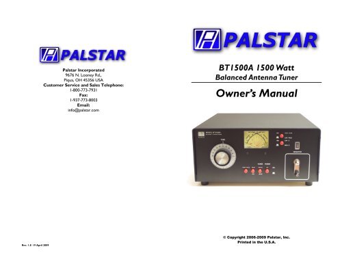
A Simple Work-Around: There are many ways to correct the problem of being<br />
unable to effect a good match on one or more bands of operation when using a<br />
balanced feedline. One of the simplest and cheapest techniques is to insert extra<br />
feedline into the length from the tuner to the antenna. Since the losses on the<br />
parallel line are very low, a few extra feet of transmission line will not be detectable<br />
by the station you are working.<br />
The sketch shows the general idea. You can insert the loop manually or with a<br />
1-800-773-7931 WWW.PALSTAR.COM<br />
The Palstar BT1500A Antenna<br />
Tuner is an American made impedance<br />
matching network.<br />
The BT1500A optimizes the performance<br />
of your antenna and<br />
transmitter by providing adjustable<br />
impedance matching using<br />
balanced dual tandem roller inductors<br />
with a shunt capacitor<br />
that can be switched to the input<br />
(transmitter) side or the output<br />
(antenna) side.<br />
The BT1500A also measures<br />
the power and Voltage Standing<br />
Wave Ratio (VSWR or SWR)<br />
which allows you to tune the<br />
SWR to the lowest ratio possible<br />
for the selected transmission<br />
frequency.<br />
A switch allows the user to<br />
choose Average or Peak metering.<br />
Also, a Peak Hold function<br />
General Description 5<br />
holds the peak reading for approximately<br />
2 seconds for easier<br />
reading.<br />
Front panel controls allow for<br />
selection between two ranges of<br />
variable capacitance, and allow<br />
the shunt capacitor to be<br />
switched between the input<br />
(transmitter) side (low Z, high<br />
pass) and the output (antenna)<br />
side (high Z, low pass).<br />
Tuning is achieved with the front<br />
panel controls. The Vernier capacitor<br />
dial allows for fine tuning<br />
with precision and accuracy,<br />
while the Inductor crank handle<br />
provides coarse adjustments.<br />
The range of the power meter<br />
(300W/3000W) is selected by a<br />
push button switch located on<br />
the front panel.<br />
1-800-773-7931 WWW.PALSTAR.COM
6 Installation<br />
Unpacking<br />
Carefully remove the BT1500A from the shipping carton<br />
and inspect it for signs of damage. If any damage is<br />
apparent, notify the transportation carrier or dealer immediately.<br />
We recommend keeping the packing carton<br />
for moving, storing or reshipping the tuner to<br />
us for repair if required.<br />
Location<br />
Select a location for the BT1500A that allows the connectors<br />
to be free from any possible contact with people,<br />
pets or objects during operation, and with unrestricted<br />
air flow for cooling.<br />
Installation Procedures<br />
Connect a coax cable from your transmitter to the RF<br />
INPUT connector on the rear panel. Keep the cable as<br />
short as possible. If you use a linear amplifier, connect<br />
your transmitter to the linear amplifier input and the linear<br />
amplifier output to the BT1500A.<br />
Connect your balanced antenna feedline to the upper<br />
white Nylon66 TM BALANCED OUTPUT posts on the<br />
back panel.<br />
WARNING: Balanced antennas will produce high<br />
RF voltages at the output post connectors. RF<br />
burns may result if touched during transmission.<br />
1-800-773-7931 WWW.PALSTAR.COM<br />
Understanding Your Tuner 15<br />
two equal series portions, one in each leg of the network. The shunt capacitor has<br />
the same value in both versions of the L-network.<br />
Unlike the single-ended L-network, the legs of the balanced L-network are both<br />
above ground potential. Hence, both the input and antenna sides of the network<br />
are balanced. In order to accommodate the single-ended transmission line from<br />
the transmitter, the tuner places a 1:1 choke (current) balun between the input<br />
side of the network and the transmitter coax connector. The balun converts the<br />
unbalanced input from the transmitter to a balanced condition for the network.<br />
As well, it suppresses currents that might otherwise appear on the braid of the<br />
transmitter cable.<br />
Limitations: Every antenna tuner, no matter what the type, has limits to the<br />
range of impedances that it will match to the 50 Ohm input. The balanced Lnetwork<br />
is no exception. Understanding those limitations will help you to effect<br />
a match on every band.<br />
The impedance presented to the tuner antenna terminals is usually expressed as a<br />
series combination of resistance and reactance, that is, R +/- jX Ohms. The Lnetwork<br />
that places its shunt capacitor on the antenna side is normally an upconverter.<br />
The limiting lower end impedance is in the vicinity of 60 to 100 Ohms<br />
resistive for a 50 Ohm input. The upper limit of impedance that the network will<br />
match is a complex function of frequency, the component values, and the amount<br />
of reactance that is part of the impedance at the tuner terminals. For most of the<br />
HF Amateur bands, the upper impedance limit of the balanced L-network in the<br />
Palstar BT1500A tuner is about 2500 +/- j2500 Ohms. This upper limit descends<br />
slowly with rising frequency so that at 30 MHz the upper limit is about 400 +/j400<br />
Ohms. The decrease in range results from the unavoidable minimum capacitance<br />
of the output variable capacitor.<br />
The impedance presented to the antenna terminals may be any value of R and any<br />
value of X. For a given R component, the tuner will require a certain setting of<br />
the coil and also the capacitor. If there is reactance at the antenna terminals, then<br />
the network requires a lower value of C if the reactance is capacitive, and a<br />
higher value of C if the reactance is inductive. The network compensates for the<br />
reactance by increasing or reducing the capacitive reactance required for a purely<br />
resistive load with only small changes in the required inductance. The amount of<br />
compensation available is a function of the maximum and minimum values of<br />
shunt capacitance and the resulting reactance of this component. With finite<br />
components, the range of reactance for which the network can compensate is<br />
always limited.<br />
As well, every matching network incurs losses within the network, mostly as a<br />
function of the Q of the inductor and the ratio of the antenna terminal impedance<br />
to the input impedance. For the balanced L-network with a shunt output capacitor,<br />
the higher the impedance to be matched, the higher the losses. The losses<br />
will be lower if the reactance at the antenna terminals is purely resistive and<br />
1-800-773-7931 WWW.PALSTAR.COM
14 Understanding Your Tuner<br />
Understanding Your PALSTAR BT15000A Tuner and Your Antenna<br />
The PALSTAR BT1500A antenna tuner is a highly flexible matching device<br />
intended for use with antennas that use balanced or parallel transmission lines.<br />
To obtain the best performance from the tuner, you should understand how the<br />
tuner works and how it relates to your antenna and feedline.<br />
Basic Operation: Examine the schematic diagram of your tuner to see all of the<br />
electronic features. In this discussion, we shall focus only upon the matching<br />
network itself. The basic circuit under discussion is a balanced L-network with<br />
the shunt capacitor on the output side.<br />
A single-ended L-network — the most common variety — uses a certain value of<br />
inductance (L) and a certain value of capacitance (C) to effect a match at a particular<br />
frequency for a particular antenna feedline impedance and length. For<br />
coaxial cable systems, the single-ended L-network provides the lowest loss of<br />
any network matching system. However, one limitation is that with the capacitor<br />
on the antenna side of the coil, the system is limited to antenna terminal impedances<br />
greater than about 50 Ohms. If we wish to use the single-ended network<br />
with a balanced feedline, we have to add a balun on the output side of the network.<br />
Baluns work best with very low values of reactance on their output terminals,<br />
a condition that is difficult to obtain with most antennas that use parallel<br />
feedlines.<br />
The balanced version of the L-network overcomes this limitation by providing a<br />
true balanced output directly from the network. For a particular antenna, operating<br />
frequency, and transmission line impedance and length, the matching circuit<br />
requires the same total circuit inductance and the same output capacitance as the<br />
single-ended network. However, the balanced circuit divides the inductance into<br />
1-800-773-7931 WWW.PALSTAR.COM<br />
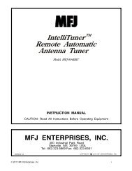
7 AT1500CV Rear Panel Description 7<br />
BALANCED OUTPUT<br />
Two Nylon high voltage connectors for<br />
output to RF balanced transmission lines.<br />
Balanced line of any impedance (300Ω,<br />
450Ω, 600Ω) can be used to feed the<br />
RF INPUT Coaxial connector<br />
for input from<br />
transmitter or amplifier.<br />
GROUND Post/wing nut<br />
ground connector.<br />
12VDC INPUT (2.1 mm plug) for<br />
12VDC. Wall transformer is supplied<br />
(U.S. only) with the tuner.<br />
FIGURE 1 REAR PANEL CONNECTORS<br />
1-800-773-7931<br />
1-800-773-7931<br />
WWW.PALSTAR.COM<br />
WWW.PALSTAR.COM
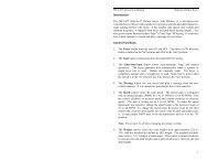
8 Front Panel AT1500CV Description Schematic<br />
8<br />
1 2 3<br />
9<br />
8<br />
1. TUNE. Dual section variable capacitor (960 &<br />
65pf). Can be switched from output to input side of network<br />
using switch # 4.<br />
2. POWER/SWR METER. Dual needle meter displays<br />
FORWARD and REFLECTED power in watts.<br />
SWR is measured where the two needles intersect on<br />
the red scale. Metering works only if the unit is provided<br />
with 12VDC at the rear power jack.<br />
3. Hi-Lo PASS. Two position switch selects Low<br />
Pass (High Z, capacitor on output side), and High Pass<br />
(Low Z, capacitor on input side). The switching is performed<br />
with a 40 amp contact relay. This function<br />
only works if the unit is provided with 12VDC at the<br />
rear power jack.<br />
4. Hi-Lo CAPACITOR. Two position switch selects<br />
the low value variable capacitor section of 65pf, or parallels<br />
the two sections for a total of 1025pf. The switching<br />
is performed with a 40 amp contact relay. This<br />
1-800-773-7931 WWW.PALSTAR.COM<br />
7<br />
6<br />
4<br />
5<br />
Operating Your BT1500A 13<br />
reading of 50-100 watts on the FORWARD scale. Adjust the<br />
TUNE and INDUCTOR controls for a minimum REFLECTED<br />
reading while maintaining a FORWARD reading of 50-100 watts<br />
using your transmitter power control.<br />
The TUNE control varies the capacitor and provide fine<br />
adjustments. The INDUCTOR crank control provides coarse<br />
adjustment.<br />
7. Read the SWR on the red scale at the point where the<br />
two needles intersect. Repeat STEP 6 until the lowest SWR reading<br />
is obtained. The SWR should be 2:1 or lower.<br />
8. When you have tuned your antenna to the best SWR, record<br />
the settings of the TUNE and INDUCTANCE controls on<br />
the chart above for future reference. When you retune, use these<br />
settings as your starting point.<br />
CAUTION: When approaching the end stops of the<br />
roller inductors, SLOW DOWN. Running the rollers<br />
too hard into the mechanical end stops on either end of<br />
the inductors can damage them.<br />
Notes:<br />
1. An SWR of 1:1 is best, but an SWR as high as 2:1 may be<br />
acceptable. Check your transmitter/amplifier manual for details.<br />
2. If you cannot get an acceptable SWR, lengthen or shorten<br />
your antenna and/or feedlines and retune.<br />
3. Any time a new or different antenna is connected, it is necessary<br />
to repeat the tuning procedure for each antenna.<br />
4. Once every 4-6 months clean the roller coil with 70% isopropyl<br />
alcohol and a clean cotton cloth. Do not transfer any of<br />
the conducting grease on the rod that guides the roller wheel as<br />
this will contaminate the windings on the roller coil body. All<br />
points of rotation are factory lubricated and this is not required<br />
by the user. All moving parts are factory lubricated with Lithium<br />
grease only.<br />
1-800-773-7931 WWW.PALSTAR.COM
12 Operating Your BT1500A<br />
Before Operating<br />
1. To avoid possible damage to the BT1500A, set TUNE, IN-<br />
DUCTOR, and POWER RANGE switches as outlined in the chart<br />
below before applying transmitter power. (NOTE: the BT1500A<br />
must be supplied with 12VDC for the switch functions and the<br />
Peak/Peak Hold metering to work.)<br />
2. Begin tuning with your transmitter/amp that is feeding the<br />
tuner set at a low output power setting (100 Watts).<br />
Tuning<br />
1. Select the band and frequency of desired operation.<br />
2. Set TUNE and INDUCTOR controls to the suggested setting<br />
before applying transmitter power (see chart - documented<br />
with 270Ω non-reactive). Actual settings will vary from antenna<br />
to antenna.<br />
3. Set your transmitter/amplifier to a low power output. If<br />
your transmitter has a TUNE position, select that position.<br />
4. If you use a linear amplifier, set it to Standby. Do not use<br />
the linear amplifier until the BT1500A is tuned. Do not exceed<br />
1000 watts continous (single tone) during operation.<br />
5. Set RANGE switch to 300W (button out).<br />
6. Key your transmitter and adjust the power level for a<br />
BAND<br />
WARNING: DO NOT OPERATE THE BT1500A<br />
WITH THE COVER OFF.<br />
TUNING SWITCH SETTING INDUCTOR<br />
SUGGESTED ACTUAL HI-C LO-C HI-Z LO-Z SUGGESTED ACTUAL<br />
160 M 66 HI-C HI-Z 156<br />
80 M 35 HI-C HI-Z 184<br />
40 M 20 HI-C HI-Z 215<br />
20 M 11 HI-C HI-Z 231<br />
17 M<br />
15 M 35 HI-C HI-Z 237<br />
12 M 18 HI-C HI-Z 238<br />
10 M 15 HI-C HI-Z 240<br />
1-800-773-7931 WWW.PALSTAR.COM<br />
ront Panel Description 9<br />
function only works if the unit is provided with<br />
12VDC at the rear power jack.<br />
5. INDUCTOR. Two 22uH roller inductors mounted<br />
in tandem, with turns counter.<br />
6. POWER. A two position button. When in the IN<br />
position, turns on meter illumination and powers the Hi-<br />
Lo Pass and Hi-Lo Capacitor switch functions and the<br />
metering functions. The unit must be provided with<br />
12VDC at the rear power jack.<br />
7. RANGE. Two-position switch selects the range of<br />
FORWARD and REFLECTED power displayed on the<br />
power meter.<br />
When the RANGE button is OUT, the FORWARD<br />
meter scale reads 300 watts full scale and the RE-<br />
FLECTED meter scale reads 60 watts full scale.<br />
When the RANGE button is IN, the FORWARD<br />
meter scale reads 3000 watts full scale and the RE-<br />
FLECTED meter reads 600 watts full scale.<br />
8. PEAK/AVERAGE. Selects between Average<br />
power reading and Peak power reading. Active circuitry<br />
provides a peak reading for SSB. For the Peak reading<br />
function to work, the POWER switch (#6) must be on.<br />
9. PEAK HOLD. When the Peak reading function is<br />
selected (#8), the Peak Hold provides an approximate<br />
2 second hold at the peak level for easy viewing.<br />
NOTE: The Peak Hold will function only if the PEAK<br />
button (#8) and the Power button (#6) are depressed<br />
as well.<br />
1-800-773-7931 WWW.PALSTAR.COM
10 Schematic Diagram<br />
1-800-773-7931 WWW.PALSTAR.COM<br />
Schematic Diagram 11<br />
1-800-773-7931 WWW.PALSTAR.COM