
You also want an ePaper? Increase the reach of your titles
YUMPU automatically turns print PDFs into web optimized ePapers that Google loves.
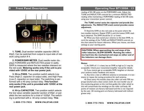
8 Front Panel AT1500CV Description Schematic<br />
8<br />
1 2 3<br />
9<br />
8<br />
1. TUNE. Dual section variable capacitor (960 &<br />
65pf). Can be switched from output to input side of network<br />
using switch # 4.<br />
2. POWER/SWR METER. Dual needle meter displays<br />
FORWARD and REFLECTED power in watts.<br />
SWR is measured where the two needles intersect on<br />
the red scale. Metering works only if the unit is provided<br />
with 12VDC at the rear power jack.<br />
3. Hi-Lo PASS. Two position switch selects Low<br />
Pass (High Z, capacitor on output side), and High Pass<br />
(Low Z, capacitor on input side). The switching is performed<br />
with a 40 amp contact relay. This function<br />
only works if the unit is provided with 12VDC at the<br />
rear power jack.<br />
4. Hi-Lo CAPACITOR. Two position switch selects<br />
the low value variable capacitor section of 65pf, or parallels<br />
the two sections for a total of 1025pf. The switching<br />
is performed with a 40 amp contact relay. This<br />
1-800-773-7931 WWW.PALSTAR.COM<br />
7<br />
6<br />
4<br />
5<br />
Operating Your BT1500A 13<br />
reading of 50-100 watts on the FORWARD scale. Adjust the<br />
TUNE and INDUCTOR controls for a minimum REFLECTED<br />
reading while maintaining a FORWARD reading of 50-100 watts<br />
using your transmitter power control.<br />
The TUNE control varies the capacitor and provide fine<br />
adjustments. The INDUCTOR crank control provides coarse<br />
adjustment.<br />
7. Read the SWR on the red scale at the point where the<br />
two needles intersect. Repeat STEP 6 until the lowest SWR reading<br />
is obtained. The SWR should be 2:1 or lower.<br />
8. When you have tuned your antenna to the best SWR, record<br />
the settings of the TUNE and INDUCTANCE controls on<br />
the chart above for future reference. When you retune, use these<br />
settings as your starting point.<br />
CAUTION: When approaching the end stops of the<br />
roller inductors, SLOW DOWN. Running the rollers<br />
too hard into the mechanical end stops on either end of<br />
the inductors can damage them.<br />
Notes:<br />
1. An SWR of 1:1 is best, but an SWR as high as 2:1 may be<br />
acceptable. Check your transmitter/amplifier manual for details.<br />
2. If you cannot get an acceptable SWR, lengthen or shorten<br />
your antenna and/or feedlines and retune.<br />
3. Any time a new or different antenna is connected, it is necessary<br />
to repeat the tuning procedure for each antenna.<br />
4. Once every 4-6 months clean the roller coil with 70% isopropyl<br />
alcohol and a clean cotton cloth. Do not transfer any of<br />
the conducting grease on the rod that guides the roller wheel as<br />
this will contaminate the windings on the roller coil body. All<br />
points of rotation are factory lubricated and this is not required<br />
by the user. All moving parts are factory lubricated with Lithium<br />
grease only.<br />
1-800-773-7931 WWW.PALSTAR.COM