
Create successful ePaper yourself
Turn your PDF publications into a flip-book with our unique Google optimized e-Paper software.
12 Operating Your BT1500A<br />
Before Operating<br />
1. To avoid possible damage to the BT1500A, set TUNE, IN-<br />
DUCTOR, and POWER RANGE switches as outlined in the chart<br />
below before applying transmitter power. (NOTE: the BT1500A<br />
must be supplied with 12VDC for the switch functions and the<br />
Peak/Peak Hold metering to work.)<br />
2. Begin tuning with your transmitter/amp that is feeding the<br />
tuner set at a low output power setting (100 Watts).<br />
Tuning<br />
1. Select the band and frequency of desired operation.<br />
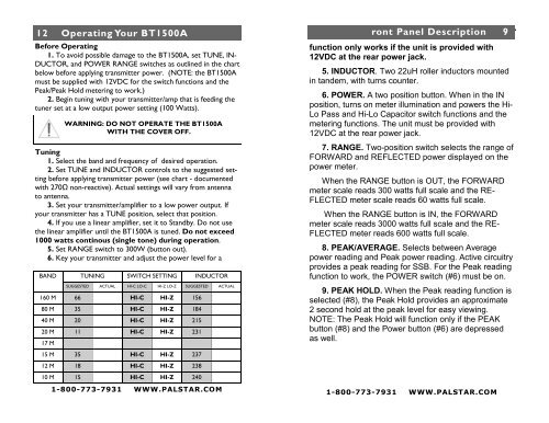
2. Set TUNE and INDUCTOR controls to the suggested setting<br />
before applying transmitter power (see chart - documented<br />
with 270Ω non-reactive). Actual settings will vary from antenna<br />
to antenna.<br />
3. Set your transmitter/amplifier to a low power output. If<br />
your transmitter has a TUNE position, select that position.<br />
4. If you use a linear amplifier, set it to Standby. Do not use<br />
the linear amplifier until the BT1500A is tuned. Do not exceed<br />
1000 watts continous (single tone) during operation.<br />
5. Set RANGE switch to 300W (button out).<br />
6. Key your transmitter and adjust the power level for a<br />
BAND<br />
WARNING: DO NOT OPERATE THE BT1500A<br />
WITH THE COVER OFF.<br />
TUNING SWITCH SETTING INDUCTOR<br />
SUGGESTED ACTUAL HI-C LO-C HI-Z LO-Z SUGGESTED ACTUAL<br />
160 M 66 HI-C HI-Z 156<br />
80 M 35 HI-C HI-Z 184<br />
40 M 20 HI-C HI-Z 215<br />
20 M 11 HI-C HI-Z 231<br />
17 M<br />
15 M 35 HI-C HI-Z 237<br />
12 M 18 HI-C HI-Z 238<br />
10 M 15 HI-C HI-Z 240<br />
1-800-773-7931 WWW.PALSTAR.COM<br />
ront Panel Description 9<br />
function only works if the unit is provided with<br />
12VDC at the rear power jack.<br />
5. INDUCTOR. Two 22uH roller inductors mounted<br />
in tandem, with turns counter.<br />
6. POWER. A two position button. When in the IN<br />
position, turns on meter illumination and powers the Hi-<br />
Lo Pass and Hi-Lo Capacitor switch functions and the<br />
metering functions. The unit must be provided with<br />
12VDC at the rear power jack.<br />
7. RANGE. Two-position switch selects the range of<br />
FORWARD and REFLECTED power displayed on the<br />
power meter.<br />
When the RANGE button is OUT, the FORWARD<br />
meter scale reads 300 watts full scale and the RE-<br />
FLECTED meter scale reads 60 watts full scale.<br />
When the RANGE button is IN, the FORWARD<br />
meter scale reads 3000 watts full scale and the RE-<br />
FLECTED meter reads 600 watts full scale.<br />
8. PEAK/AVERAGE. Selects between Average<br />
power reading and Peak power reading. Active circuitry<br />
provides a peak reading for SSB. For the Peak reading<br />
function to work, the POWER switch (#6) must be on.<br />
9. PEAK HOLD. When the Peak reading function is<br />
selected (#8), the Peak Hold provides an approximate<br />
2 second hold at the peak level for easy viewing.<br />
NOTE: The Peak Hold will function only if the PEAK<br />
button (#8) and the Power button (#6) are depressed<br />
as well.<br />
1-800-773-7931 WWW.PALSTAR.COM