Intersection Design Studies - Illinois Department of Transportation
Intersection Design Studies - Illinois Department of Transportation
Intersection Design Studies - Illinois Department of Transportation

You also want an ePaper? Increase the reach of your titles
YUMPU automatically turns print PDFs into web optimized ePapers that Google loves.
Chapter Fourteen<br />
INTERSECTION DESIGN<br />
STUDIES<br />
BUREAU OF DESIGN AND ENVIRONMENT MANUAL
<strong>Illinois</strong> INTERSECTION DESIGN STUDIES September 2010<br />
Chapter Fourteen<br />
INTERSECTION DESIGN STUDIES<br />
Table <strong>of</strong> Contents<br />
Section Page<br />
14-1 WARRANTS FOR THE PREPARATION OF INTERSECTION DESIGN<br />
STUDIES ................................................................................................................. 14-1.1<br />
14-2 PREPARATION OF INTERSECTION DESIGN STUDIES ..................................... 14-2.1<br />
14-3 DATA REQUIRED FOR INTERSECTION DESIGN STUDIES ............................... 14-3.1<br />
14-4 INTERSECTION DESIGN STUDY PROCESSING ................................................. 14-4.1<br />
HARD COPIES UNCONTROLLED<br />
14-i
<strong>Illinois</strong> INTERSECTION DESIGN STUDIES September 2010<br />
14-ii<br />
HARD COPIES UNCONTROLLED
<strong>Illinois</strong> INTERSECTION DESIGN STUDIES September 2010<br />
Chapter Fourteen<br />
INTERSECTION DESIGN STUDIES<br />
An <strong>Intersection</strong> <strong>Design</strong> Study (IDS) is a graphic representation <strong>of</strong> a proposed treatment for the<br />
development or improvement <strong>of</strong> an intersection facility. It is based on an analysis <strong>of</strong> traffic<br />
needs and an evaluation <strong>of</strong> physical and economic elements at the intersection site. Chapter 14<br />
presents the <strong>Department</strong>’s criteria for the preparation <strong>of</strong> an IDS. Chapter 36 presents the<br />
detailed design criteria for intersections.<br />
The primary purpose <strong>of</strong> an IDS is to provide a review medium for use by the district, BDE, and<br />
the general public. The IDS also provides a file reference that documents all pertinent data and<br />
information controlling the design <strong>of</strong> the intersection improvement.<br />
14-1 WARRANTS FOR THE PREPARATION OF INTERSECTION DESIGN STUDIES<br />
Prepare an IDS for intersections if any <strong>of</strong> the following conditions apply:<br />
� The study location is an intersection <strong>of</strong> two marked routes.<br />
� The improvement is intersected by either:<br />
� a rural highway that has an existing 30th maximum hourly volume greater than<br />
300 vehicles or additional lanes and/or channelization is proposed on one or both<br />
routes; or<br />
� an urban highway that has an existing 30th maximum hourly volume greater than<br />
400 vehicles or additional lanes and/or channelization is proposed on one or both<br />
routes.<br />
� Where complex conditions exist at the intersection (e.g., high crash rate, adverse terrain<br />
features, geometric features that will be difficult to correct due to the extent <strong>of</strong> cultural<br />
development).<br />
� Where the proposed improvement will include a roundabout.<br />
� When requested by the district or BDE in accordance with the engineering study and<br />
advance engineering data requirements in the ILMUTCD.<br />
HARD COPIES UNCONTROLLED<br />
14-1.1
<strong>Illinois</strong> INTERSECTION DESIGN STUDIES December 2009<br />
14-1.2<br />
HARD COPIES UNCONTROLLED
<strong>Illinois</strong> INTERSECTION DESIGN STUDIES September 2010<br />
14-2 PREPARATION OF INTERSECTION DESIGN STUDIES<br />
Prepare IDS plan sheets on CADD. For guidance on the preparation <strong>of</strong> plan or pr<strong>of</strong>ile sheets,<br />
see Section 63-4.01. To facilitate uniformity, use the following sheet formats:<br />
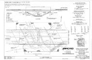
1. Sheet No. 1. An example <strong>of</strong> a Layout Sheet No. 1 is illustrated in Figure 14-2.A. In<br />
urban areas, the intersection layout is usually drawn at a scale ratio <strong>of</strong> 1 in = 50 ft (1:500<br />
metric) and in rural areas 1 in = 100 ft (1:1000 metric) or 1 in = 50 ft (1:500 metric).<br />
Sheet No. 1 is the cover sheet and contains the following items:<br />
� capacity analysis table,<br />
� turning movement diagram,<br />
� traffic data table,<br />
� north arrow,<br />
� data block for elements controlling design,<br />
� phasing diagram,<br />
� location map box,<br />
� general notes block, and<br />
� signature and title block in the lower right-hand corner.<br />
2. Sheet No. 2. Sheet No. 2 is a supplemental sheet for intersection details. Depending on<br />
the complexity <strong>of</strong> the intersection and the need to show special details or cross sections,<br />
this sheet may not be required. In urban areas, the scale ratio is usually 1 in = 20 ft<br />
(1:250 metric) and in rural areas 1 in = 50 ft (1:500 metric). Also include the following<br />
items on the sheet:<br />
� title block in the lower right-hand corner; and<br />
� sheet index block in the upper right-hand corner indicating the route, section,<br />
county, and sheet numbers.<br />
3. Sheet No. 3. Sheet No. 3 is a typical grid sheet for showing pr<strong>of</strong>iles. Use the format<br />
illustrated in Figure 14-2.B. Also include the following items on the sheet:<br />
� title block in the lower right-hand corner; and<br />
� sheet index block in the upper right-hand corner indicating the route, section,<br />
county, and sheet numbers.<br />
HARD COPIES UNCONTROLLED<br />
14-2.1
<strong>Illinois</strong> INTERSECTION DESIGN STUDIES December 2009<br />
14-2.2<br />
HARD COPIES UNCONTROLLED
<strong>Illinois</strong> INTERSECTION DESIGN STUDIES December 2009<br />
HARD COPIES UNCONTROLLED<br />
14-2.3
<strong>Illinois</strong> INTERSECTION DESIGN STUDIES September 2010<br />
14-2.4<br />
HARD COPIES UNCONTROLLED
<strong>Illinois</strong> INTERSECTION DESIGN STUDIES September 2010<br />
14-3 DATA REQUIRED FOR INTERSECTION DESIGN STUDIES<br />
Document the following data in the IDS:<br />
1. Elements Controlling <strong>Design</strong>. Chapter 36 presents the design criteria for intersections.<br />
On Sheet No. 1, list all pertinent elements affecting the design <strong>of</strong> the intersection<br />
including:<br />
� the intersection route designation including highway functional classification,<br />
SRA Route designation, if appropriate, proposed design speed, and existing and<br />
design traffic (ADT and year) for both intersecting routes;<br />
� the preferential route;<br />
� the anticipated year <strong>of</strong> construction;<br />
� the type <strong>of</strong> traffic control including:<br />
+ a statement indicating whether signals will be installed or adjusted;<br />
+ the warrant, or combination <strong>of</strong> warrants, from the ILMUTCD justifying the<br />
use <strong>of</strong> signal control; and<br />
+ use <strong>of</strong> a roundabout;<br />
� design criteria;<br />
� design vehicle;<br />
� truck route designation;<br />
� existing and proposed posted speeds (mph) on all intersection approaches<br />
(proposed posted speeds should be equal to or less than the design speeds);<br />
and<br />
� pedestrian and bicycle usage at intersection.<br />
2. General Notes. Include the following information in the general notes on Sheet No. 1:<br />
a. Grades. Where all existing grades to remain are greater than 1% or in all cases<br />
with any new or altered grades, include a statement that pr<strong>of</strong>iles are shown for<br />
both intersecting roads and show them on Sheet No. 3. If existing grades are to<br />
remain and are all less than 1%, indicate this fact and state that no pr<strong>of</strong>iles are<br />
shown.<br />
b. Curb and Gutter. Indicate the type <strong>of</strong> curb and gutter to be used on the outer<br />
edges <strong>of</strong> the traveled way, shoulders, channelizing islands, and corner islands.<br />
Only use mountable type curbing on corner islands.<br />
HARD COPIES UNCONTROLLED<br />
14-3.1
<strong>Illinois</strong> INTERSECTION DESIGN STUDIES September 2010<br />
14-3.2<br />
c. Dimensions. Indicate the type <strong>of</strong> dimensioning used (e.g., edge-to-edge <strong>of</strong><br />
pavement, edge-to-edge <strong>of</strong> traveled way).<br />
d. <strong>Design</strong> Exceptions. List any deviations from design criteria (see Section 31-8)<br />
and typical traffic control practice (e.g., large truck turning encroachments, lane<br />
widths less than <strong>Department</strong> criteria, less than desirable level <strong>of</strong> service, less<br />
than desirable storage length for queued vehicles). Include the justification for<br />
design exceptions in the Phase I report.<br />
e. Access to State Highways. State if the design complies with the criteria in<br />
Section 36-7 or list any instances <strong>of</strong> noncompliance.<br />
f. Crashes. Note if the intersection is a Five Percent Report location (FPR) and, if<br />
so, what year.<br />
g. Terrain. Describe any unusual terrain features that could affect the design.<br />
h. Cultural Development. Indicate adjacent cultural development that influences the<br />
intersection layout.<br />
i. Improvement Type. List the type <strong>of</strong> improvement (e.g., new construction,<br />
reconstruction, 3R, safety).<br />
j. Bicycle Route. Note the existence <strong>of</strong> designated bicycle routes through the<br />
intersection.<br />
k. Sight Distance. On two-way stop-controlled intersections, note if intersection<br />
sight distance is met.<br />
l. Verification. Note the method used to verify sufficiency <strong>of</strong> intersection to<br />
accommodate turning movements <strong>of</strong> the design vehicle.<br />
m. Right-<strong>of</strong>-Way. Indicate if proposed right-<strong>of</strong>-way limits for the intersection are<br />
preliminary.<br />
n. Truck Routes. Note the existence <strong>of</strong> designated truck routes through the<br />
intersection.<br />
o. Other. Include any additional information not listed elsewhere that will aid in the<br />
review <strong>of</strong> the IDS.<br />
3. Capacity Analysis. Perform and document the capacity analysis <strong>of</strong> the IDS according to<br />
the following guidelines:<br />
a. Source Document. Use the Highway Capacity Manual and the Highway<br />
Capacity S<strong>of</strong>tware (distributed by the McTrans Center for Microcomputers in<br />
<strong>Transportation</strong>) for the capacity analyses. The use <strong>of</strong> any other capacity<br />
techniques and s<strong>of</strong>tware must be first approved by BDE; see Section 36-1.07.<br />
HARD COPIES UNCONTROLLED
<strong>Illinois</strong> INTERSECTION DESIGN STUDIES September 2010<br />
b. Signal Phasing. In diagrammatic form, illustrate the proposed signal phasing<br />
required to obtain the desired level <strong>of</strong> service. Orient the signal phasing diagram<br />
to be consistent with the plan view <strong>of</strong> the intersection and any other pertinent<br />
diagrams.<br />
c. Results. Document the data and results <strong>of</strong> the capacity analysis on Sheet No. 1<br />
for each leg <strong>of</strong> the intersection in a table as illustrated in Figure 14-3.A.<br />
4. Traffic Data. Provide the following traffic data on Sheet No 1:<br />
a. Traffic Movements. Provide a tabular listing <strong>of</strong> all movements to and from each<br />
leg <strong>of</strong> the intersection. Use the format illustrated in Figure 14-3.B. Also, prepare<br />
a traffic diagram for the design year showing all DHV movements within the<br />
intersection. Orient the traffic diagram to be consistent with the plan view <strong>of</strong> the<br />
intersection and any other pertinent diagrams.<br />
b. Existing Volumes. Calculate the 8th maximum hourly volume per day from actual<br />
traffic counts to determine whether traffic signal warrants are met. See the<br />
ILMUTCD for additional guidance.<br />
c. Proposed Volumes. For new intersections or where proposed intersection<br />
improvements for large developments will significantly increase traffic volumes,<br />
traffic signals may be justified where the 8th maximum hourly volume three years<br />
after construction exceeds the values stated in the warrants. The three years<br />
time frame should be increased in the event <strong>of</strong> staged development. The 8th<br />
maximum daily hourly volume may be considered as 55% <strong>of</strong> the projected 30th<br />
maximum hour volume. See the ILMUTCD for additional guidance.<br />
d. Pedestrians. Where pedestrian control signal heads are proposed, provide a<br />
pedestrian count.<br />
5. <strong>Intersection</strong> Layout and <strong>Design</strong>. Provide the following intersection layout and design<br />
information on Sheets No. 1 and No. 2:<br />
a. Centerline. Show the centerline information for all proposed and existing curves<br />
within the immediate area <strong>of</strong> the intersection. Include superelevation rates and<br />
transition stations. Label the station equation for all intersecting side roads.<br />
b. Angle. Note the angle <strong>of</strong> intersection between the two roadways.<br />
c. Location Map. Provide a small scale location map, covering a sufficient area to<br />
properly identify the location <strong>of</strong> the improvement. It should portray the existing<br />
street or local road network and any municipalities adjacent to the improvement.<br />
Layout the map with North in the same direction as shown on the intersection<br />
layout.<br />
d. Auxiliary Lane Lengths. Indicate lengths for all auxiliary lanes.<br />
HARD COPIES UNCONTROLLED<br />
14-3.3
<strong>Illinois</strong> INTERSECTION DESIGN STUDIES September 2010<br />
14-3.4<br />
e. Tapers. Indicate all taper lengths and rates.<br />
f. Scales. Provide a bar scale on each sheet.<br />
g. Topographic Features. Indicate all limiting topographic features or cultural<br />
developments including:<br />
� existing and proposed access driveways;<br />
� existing and proposed right-<strong>of</strong>-way lines and any access control limits;<br />
� property lines;<br />
� property owners, business names, land uses, and buildings;<br />
� sidewalks, curb ramps, and other accessibility requirements, see Chapter<br />
58; and<br />
� other factors controlling the intersection design (e.g., retaining walls,<br />
utilities, gasoline pumps, other appurtenances).<br />
h. Signals. Show the proposed signal locations and signal phasing diagram.<br />
Prepare these according to the criteria and guidelines presented in Chapter 57.<br />
This information is required to ensure compatibility with other design elements,<br />
right-<strong>of</strong>-way, and traffic flow (progression).<br />
i. Signs. For complex intersections, show the proper placement <strong>of</strong> signs and traffic<br />
control devices. Because signing distance and legend requirements could<br />
influence the design <strong>of</strong> complex facilities, include a preliminary signing plan with<br />
the IDS for all complex intersection designs.<br />
j. Striping. Include the proposed striping details on the IDS.<br />
k. Control Points. Provide the station and <strong>of</strong>fset <strong>of</strong> all control points, including all<br />
island noses, radius return points <strong>of</strong> curvature and tangency, and centerline or<br />
baseline control points.<br />
6. Title Block. Only the individual personally responsible for the intersection design will<br />
occupy the “<strong>Design</strong>ed By” line in the title block.<br />
HARD COPIES UNCONTROLLED
<strong>Illinois</strong> INTERSECTION DESIGN STUDIES September 2010<br />
HARD COPIES UNCONTROLLED<br />
CAPACITY DESIGN ANALYSIS<br />
Figure 14-3.A<br />
14-3.5
<strong>Illinois</strong> INTERSECTION DESIGN STUDIES September 2010<br />
14-3.6<br />
HARD COPIES UNCONTROLLED<br />
TRAFFIC DATA SUMMARY<br />
Figure 14-3.B
<strong>Illinois</strong> INTERSECTION DESIGN STUDIES May 2011<br />
14-4 INTERSECTION DESIGN STUDY PROCESSING<br />
<strong>Intersection</strong> design studies are normally prepared under the direction <strong>of</strong> and approved by the<br />
District Geometrics Engineer. Upon completion <strong>of</strong> the IDS, it is approved by the district as<br />
illustrated in the signature block in Figure 14-2.A and included in the Phase I report. BDE will<br />
review and approve IDSs if requested by the district or if the district does not have a qualified<br />
geometrics engineer.<br />
When projects require an IDS, the district should not conduct public involvement activities<br />
without an approved IDS. When an IDS is prepared by a qualified Geometrics Engineer,<br />
reviewed according to current geometric design policies, and approved by the District<br />
Geometrics Engineer, it may be included as part <strong>of</strong> the Phase I report. Upon approval <strong>of</strong> the<br />
IDS, the district will submit a completed BDE 2602 template to BDE for status information <strong>of</strong> the<br />
IDS.<br />
Final approval <strong>of</strong> an IDS is given with the design approval <strong>of</strong> the final Phase I report. This<br />
ensures the consideration <strong>of</strong> social, economic, and environmental factors and public comments<br />
that could affect the design elements <strong>of</strong> an intersection. In addition, an crash analysis and<br />
relevant collision diagrams may be reviewed concurrently with the IDS.<br />
If intersection conditions are complex, the district, at its option, may forward the IDS to BDE for<br />
early review. In this case, the IDS is reviewed with particular emphasis on compliance with<br />
accepted design practices, methods <strong>of</strong> managing or controlling access, intersection capacity,<br />
signal phasing, operational safety, efficiency, and any needed design exceptions. BDE may<br />
recommend changes to the IDS. If changes are recommended, the comments are forwarded to<br />
the district for revision. After the revised IDS is reviewed and considered satisfactory, it is then<br />
approved by the District Geometrics Engineer for inclusion in the Phase I report.<br />
HARD COPIES UNCONTROLLED<br />
14-4.1
<strong>Illinois</strong> INTERSECTION DESIGN STUDIES May 2011<br />
14-4.2<br />
HARD COPIES UNCONTROLLED