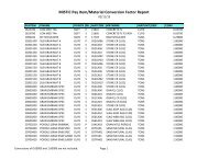
Mechanically Stabilized Earth Retaining Walls - Illinois Department ...
Mechanically Stabilized Earth Retaining Walls - Illinois Department ...
Mechanically Stabilized Earth Retaining Walls - Illinois Department ...

You also want an ePaper? Increase the reach of your titles
YUMPU automatically turns print PDFs into web optimized ePapers that Google loves.
MECHANICALLY STABILIZED EARTH RETAINING WALLS<br />
Effective: February 3, 1999<br />
Revised: February 6, 2013<br />
Description. This work shall consist of preparing the design, furnishing the materials, and<br />
constructing the mechanically stabilized earth (MSE) retaining wall to the lines, grades and<br />
dimensions shown in the contract plans and as directed by the Engineer.<br />
General. The MSE wall consists of a concrete leveling pad, precast concrete face panels, a soil<br />
reinforcing system, select fill and concrete coping (when specified). The soil reinforcement shall<br />
have sufficient strength, quantity, and pullout resistance, beyond the failure surface within the<br />
select fill, as required by design. The material, fabrication, and construction shall comply with<br />
this Special Provision and the requirements specified by the supplier of the wall system selected<br />
by the Contractor for use on the project.<br />
The MSE retaining wall shall be one of the following pre-approved wall systems:<br />
Company Name: Wall System<br />
<strong>Earth</strong> Tec International, LLC: <strong>Earth</strong>Trac HA<br />
Sanders Pre-Cast Concrete Systems Company: Sanders MSE Wall<br />
Shaw Technologies: Strengthened Soil<br />
Sine Wall, LLC: Sine Wall<br />
SSL Construction Products: MSE Plus<br />
T&B Structural Systems: <strong>Stabilized</strong> <strong>Earth</strong><br />
Tensar <strong>Earth</strong> Technologies : ARES Wall<br />
The Reinforced <strong>Earth</strong> Company: GeoMega System<br />
The Reinforced <strong>Earth</strong> Company: Reinforced <strong>Earth</strong><br />
The Reinforced <strong>Earth</strong> Company: Retained <strong>Earth</strong><br />
Tricon Precast: Tricon Retained Soil<br />
Tricon Precast: Tri-Web Retained Soil<br />
Pre-approval of the wall system does not include material acceptance at the jobsite.<br />
Submittals. The wall system supplier shall submit complete design calculations and shop<br />
drawings to the Engineer according to Article 1042.03(b) of the Standard Specifications no later<br />
than 90 days prior to beginning construction of the wall. No work or ordering of materials for the<br />
structure shall be done by the Contractor until the submittal has been approved in writing by the<br />
Engineer. All submittals shall be sealed by an <strong>Illinois</strong> Licensed Structural Engineer and shall<br />
include all details, dimensions, quantities and cross sections necessary to construct the wall and<br />
shall include, but not be limited to, the following items:<br />
(a) Plan, elevation and cross section sheet(s) for each wall showing the following:<br />
(1) A plan view of the wall indicating the offsets from the construction centerline to the<br />
face of the wall at all changes in horizontal alignment. The plan view shall show the<br />
limits of soil reinforcement and stations where changes in length and/or size of
einforcement occur. The centerline shall be shown for all drainage structures or<br />
pipes behind or passing through and/or under the wall.<br />
(2) An elevation view of the wall indicating the elevations of the top of the panels. These<br />
elevations shall be at or above the top of exposed panel line shown on the contract<br />
plans. This view shall show the elevations of the top of the leveling pads, all steps in<br />
the leveling pads and the finished grade line. Each panel type, the number, size and<br />
length of soil reinforcement connected to the panel shall be designated. The<br />
equivalent uniform applied service (unfactored) nominal bearing pressure shall be<br />
shown for each designed wall section.<br />
(3) A listing of the summary of quantities shall be provided on the elevation sheet of<br />
each wall.<br />
(4) Typical cross section(s) showing the limits of the reinforced select fill volume<br />
included within the wall system, soil reinforcement, embankment material placed<br />
behind the select fill, precast face panels, and their relationship to the right-of-way<br />
limits, excavation cut slopes, existing ground conditions and the finished grade line.<br />
(5) All general notes required for constructing the wall.<br />
(b) All details for the concrete leveling pads, including the steps, shall be shown. The top of<br />
the leveling pad shall be located at or below the theoretical top of the leveling pad line<br />
shown on the contract plans. The theoretical top of leveling pad line shall be 3.5 ft. (1.1<br />
m) below finished grade line at the front face of the wall, unless otherwise shown on the<br />
plans.<br />
(c) Where concrete coping or barrier is specified, the panels shall extend up into the coping<br />
or barrier as shown in the plans. The top of the panels may be level or sloped to satisfy<br />
the top of exposed panel line shown on the contract plans. Cast-in-place concrete will<br />
not be an acceptable replacement for panel areas below the top of exposed panel line.<br />
As an alternative to cast in place coping, the Contractor may substitute a precast coping,<br />
the details of which must be included in the shop drawings and approved by the<br />
Engineer.<br />
(d) All panel types shall be detailed. The details shall show all dimensions necessary to<br />
cast and construct each type of panel, all reinforcing steel in the panel, and the location<br />
of soil reinforcement connection devices embedded in the panels. These panel embed<br />
devices shall not be in contact with the panel reinforcement steel.<br />
(e) All details of the wall panels and soil reinforcement placement around all appurtenances<br />
located behind, on top of, or passing through the soil reinforced wall volume such as<br />
parapets with anchorage slabs, coping, foundations, and utilities etc. shall be clearly<br />
indicated. Any modifications to the design of these appurtenances to accommodate a<br />
particular system shall also be submitted.
(f) When specified on the contract plans, all details of architectural panel treatment,<br />
including color, texture and form liners shall be shown.<br />
(g) The details for the connection between concrete panels, embed devices, and soil<br />
reinforcement shall be shown.<br />
(h) When pile sleeves are specified, the pile sleeve material, shape, and wall thickness shall<br />
be submitted to the Engineer for approval. It shall have adequate strength to withstand<br />
the select fill pressures without collapse until after completion of the wall settlement.<br />
The annulus between the pile and the sleeve shall be as small as possible while still<br />
allowing it to be filled with loose dry sand after wall erection.<br />
The initial submittal shall include three sets of shop drawings and one set of calculations. One<br />
set of drawings will be returned to the Contractor with any corrections indicated. After approval,<br />
the Contractor shall furnish the Engineer with ten (10) sets of corrected plan prints for<br />
distribution by the <strong>Department</strong>. No work or ordering of materials for the structure shall be done<br />
until the submittal has been approved by the Engineer.<br />
Materials. The MSE walls shall conform to the supplier's standards as previously approved by<br />
the <strong>Department</strong>, and the following:<br />
(a) The soil reinforcing system, which includes the soil reinforcement, and all connection<br />
devices, shall be according to the following:<br />
(1) Inextensible Soil Reinforcement. Steel reinforcement shall be according ASTM A 572<br />
Grade 65 (450), ASTM A 1011 or ASTM A 463 Grade 50 (345). The steel strips shall be<br />
either epoxy coated, aluminized Type 2, or galvanized. Epoxy coatings shall be<br />
according to Article 1006.10(a)(2), except the minimum thickness of epoxy coating shall<br />
be 18 mils (457 microns). No bend test will be required. Aluminized Type 2-100 shall be<br />
according to ASTM A 463. Galvanizing shall be according to AASHTO M 111 or ASTM<br />
A 653 with touch up of damage according to ASTM A 780.<br />
(2) Extensible Soil Reinforcement. Geosynthetic reinforcement shall be monolithically<br />
fabricated from virgin high density polyethylene (HDPE) or high tenacity polyester<br />
(HTPET) resins having the following properties verified by mill certifications:<br />
Property for Geosynthetic Reinforcement Value Test<br />
Minimum Tensile Strength ** ASTM D 6637<br />
** as specified in the approved design calculations and shown on the shop drawings.<br />
Property for HDPE Value Test<br />
Melt Flow Rate (g/cm) 0.060 – 0.150 ASTM D 1238, Procedure B<br />
Density (g/cu m) 0.941 – 0.965 ASTM D 792<br />
Carbon Black 2% (min) ASTM D 4218
Property for HTPET Value Test<br />
Carboxyl End Group (max) (mmol/kg) 25,000 GRI-GG8<br />
(3) Panel Embed/Connection Devices. Panel embeds and connection devices shall be<br />
according to the following.<br />
a. Metallic panel embed/connection devices and connection hardware shall be<br />
galvanized according to AASHTO M 232 and shall be according to the following.<br />
Mesh and Loop Embeds ASTM A 706 (A 706M)<br />
Tie Strip Embeds AASHTO M 270/M 270M Grade 50 (345) or<br />
ASTM A 1011 HSLAS Grade 50 (345) Class 2<br />
b. Non metallic panel embed/connection devices typically used with geosynthetic soil<br />
reinforcement shall be manufactured from virgin or recycled polyvinyl chloride having<br />
the following properties:<br />
Property for Polyvinyl Chloride Value Test<br />
Heat Deflection Temperature (F) 155 - 164 ASTM D 1896<br />
Notched IZOD 1/8 inch @ 73F (ft-lb/in) 4 – 12 ASTM D 256<br />
Coefficient of Linear Exp. (in/in/F) 3.5 – 4.5 ASTM D 696<br />
Hardness, Shore D 79 ASTM D 2240<br />
Property for Polypropylene Value Test<br />
Melt Flow Rate (g/cm) 0.060 – 0.150 ASTM D 1238, Procedure B<br />
Density (g/cu m) 0.88 – 0.92 ASTM D 792<br />
(b) The select fill, defined as the material placed in the reinforced volume behind the wall, shall<br />
be according to Sections 1003 and 1004 of the Standard Specifications and the following:<br />
(1) Select Fill Gradation. Either a coarse aggregate or a fine aggregate may be used. For<br />
coarse aggregate, gradations CA 6 thru CA 16 may be used. If an epoxy coated<br />
reinforcing is used, the coarse aggregate gradations shall be limited to CA 12 thru CA<br />
16. For fine aggregate, gradations FA 1, FA 2, or FA 20 may be used.<br />
(2) Select Fill Quality. The coarse or fine aggregate shall have a maximum sodium sulfate<br />
(Na2SO4) loss of 15 percent according to <strong>Illinois</strong> Modified AASHTO T 104.<br />
(3) Select Fill Internal Friction Angle. The effective internal friction angle for the coarse or<br />
fine aggregate shall be a minimum 34 degrees according to AASHTO T 236 on samples<br />
compacted to 95 percent density according to <strong>Illinois</strong> Modified AASHTO T 99. The<br />
AASHTO T 296 test with pore pressure measurement may be used in lieu of AASHTO T
236. If the vendor’s design uses a friction angle higher than 34 degrees, as indicated on<br />
the approved shop drawings, this higher value shall be taken as the minimum required.<br />
(4) Select Fill and Steel Reinforcing. When steel reinforcing is used, the select fill shall<br />
meet the following requirements.<br />
a. The pH shall be 5.0 to 10.0 according to <strong>Illinois</strong> Modified AASHTO T 289.<br />
b. The resistivity according to <strong>Illinois</strong> Modified AASHTO T 288 shall be greater than<br />
3000 ohm centimeters for epoxy coated and galvanized reinforcement, and 1500<br />
ohm centimeters for Aluminized Type 2. However, the resistivity requirement is not<br />
applicable to CA 7, CA 8, CA 11, CA 12, CA 13, CA 14, CA 15, and CA 16.<br />
c. The chlorides shall be less than 100 parts per million according to <strong>Illinois</strong> Modified<br />
AASHTO T 291 or ASTM D 4327. For either test, the sample shall be prepared<br />
according to <strong>Illinois</strong> Modified AASHTO T 291.<br />
d. The sulfates shall be less than 200 parts per million according to <strong>Illinois</strong> Modified<br />
AASHTO T 290 or ASTM D 4327. For either test, the sample shall be prepared<br />
according to <strong>Illinois</strong> Modified AASHTO T 290.<br />
e. The organic content shall be a maximum 1.0 percent according to <strong>Illinois</strong> Modified<br />
AASHTO T 267.<br />
(5) Select Fill and Geosynthetic Reinforcing. When geosynthetic reinforcing is used, the<br />
select fill pH shall be 4.5 to 9.0 according to <strong>Illinois</strong> Modified AASHTO T 289.<br />
(6) Test Frequency. Prior to start of construction, the Contractor shall provide internal<br />
friction angle and pH test results, to show the select fill material meets the specification<br />
requirements. In addition, resistivity, chlorides, sulfates, and organic content test results<br />
will be required if steel reinforcing is used. The laboratory performing the <strong>Illinois</strong><br />
Modified AASHTO T 288 test shall be approved by the <strong>Department</strong> according to the<br />
current Bureau of Materials and Physical Research Policy Memorandum “Minimum<br />
Laboratory Requirements for Resistivity Testing”. All test results shall not be older than<br />
12 months. In addition, a sample of select fill material will be obtained for testing and<br />
approval by the <strong>Department</strong>. Thereafter, the minimum frequency of sampling and<br />
testing by the department at the jobsite will be one per 40,000 tons (36,300 metric tons)<br />
of select fill material. Testing to verify the internal friction angle will be required when the<br />
wall design utilizes a minimum effective internal friction angle greater than 34 degrees,<br />
or when crushed coarse aggregate is not used.<br />
(c) The embankment material behind the select fill shall be according to Section 202 and/or<br />
Section 204. An embankment unit weight of 120 lbs/cubic foot (1921 kg/cubic meter) and<br />
an effective friction angle of 30 degrees shall be used in the wall system design, unless<br />
otherwise indicated on the plans.<br />
(d) The geosynthetic filter material used across the panel joints shall be either a non-woven<br />
needle punch polyester or polypropylene or a woven monofilament polypropylene with a<br />
minimum width of 12 in. (300 mm) and a minimum non-sewn lap of 6 in. (150 mm) where<br />
necessary.
(e) The bearing pads shall be rubber, neoprene, polyvinyl chloride, or polyethylene of the type<br />
and grade as recommended by the wall supplier.<br />
(f) All precast panels shall be manufactured with Class PC concrete according to Section 504,<br />
Article 1042.02, Article 1042.03, and the following requirements:<br />
(1) The minimum panel thickness shall be 5 1/2 in. (140 mm).<br />
(2) The minimum reinforcement bar cover shall be 1 1/2 in. (38 mm).<br />
(3) The panels shall have a ship lap or tongue and groove system of overlapping joints<br />
between panels designed to conceal joints and bearing pads.<br />
(4) The panel reinforcement shall be according to Article 1006.10 (a)(2).<br />
(5) All dimensions shall be within 3/16 in. (5 mm).<br />
(6) Angular distortion with regard to the height of the panel shall not exceed 0.2 inches in 5<br />
ft (5 mm in 1.5 m).<br />
(7) Surface defects on formed surfaces measured on a length of 5 ft. (1.5 m) shall not be<br />
more than 0.1 in. (2.5 mm).<br />
(8) The panel embed/connection devices shall be cast into the facing panels with a<br />
tolerance not to exceed 1 in. (25 mm) from the locations specified on the approved shop<br />
drawings.<br />
Unless specified otherwise, concrete surfaces exposed to view in the completed wall shall be<br />
finished according to Article 503.15(a). The back face of the panel shall be roughly screeded to<br />
eliminate open pockets of aggregate and surface distortions in excess of 1/4 in. (6 mm).<br />
Design Criteria. The design shall be according to the appropriate AASHTO Design<br />
Specifications noted on the plans for <strong>Mechanically</strong> <strong>Stabilized</strong> <strong>Earth</strong> <strong>Walls</strong> except as modified<br />
herein. The wall supplier shall be responsible for all internal stability aspects of the wall design<br />
and shall supply the <strong>Department</strong> with computations for each designed wall section. The<br />
analyses of settlement, bearing capacity and overall slope stability will be the responsibility of<br />
the <strong>Department</strong>.<br />
External loads, such as those applied through structure foundations, from traffic or railroads,<br />
slope surcharge etc., shall be accounted for in the internal stability design. The presence of all<br />
appurtenances behind, in front of, mounted upon, or passing through the wall volume such as<br />
drainage structures, utilities, structure foundation elements or other items shall be accounted for<br />
in the internal stability design of the wall.
The design of the soil reinforcing system shall be according to the applicable AASHTO or<br />
AASHTO LRFD Design Specifications for “Inextensible” steel or “Extensible” geosynthetic<br />
reinforcement criteria. The reduced section of the soil reinforcing system shall be sized to<br />
allowable stress levels at the end of a 75 year design life.<br />
Steel soil reinforcing systems shall be protected by on of the following; epoxy coating,<br />
galvanizing or aluminizing. The design life for epoxy shall be 16 years. The corrosion<br />
protection for the balance of the 75 year total design life shall be provided using a sacrificial<br />
steel thickness computed for all exposed surfaces according to the applicable AASHTO or<br />
AASHTO LRFD Design Specifications.<br />
Geosynthetic soil reinforcing systems shall be designed to account for the strength reduction<br />
due to long-term creep, chemical and biological degradation, as well as installation damage.<br />
To prevent out of plane panel rotations, the soil reinforcement shall be connected to the<br />
standard panels in at least two different elevations, vertically spaced no more than 30 in. (760<br />
mm) apart.<br />
The panel embed/soil reinforcement connection capacity shall be determined according to the<br />
applicable AASHTO or AASHTO LRFD Design Specifications.<br />
The factor of safety for pullout resistance in the select fill shall not be less than 1.5, based on<br />
the pullout resistance at 1/2 in. (13 mm) deformation. Typical design procedures and details,<br />
once accepted by the <strong>Department</strong>, shall be followed. All wall system changes shall be<br />
submitted in advance to the <strong>Department</strong> for approval.<br />
For aesthetic considerations and differential settlement concerns, the panels shall be erected in<br />
such a pattern that the horizontal panel joint line is discontinuous at every other panel. This<br />
shall be accomplished by alternating standard height and half height panel placement along the<br />
leveling pad. Panels above the lowest level shall be standard size except as required to satisfy<br />
the top of exposed panel line shown on the contract plans.<br />
At locations where the plans specify a change of panel alignment creating an included angle of<br />
150 degrees or less, precast corner joint elements will be required. This element shall separate<br />
the adjacent panels by creating a vertical joint secured by means of separate soil reinforcement.<br />
Isolation or slip joints, which are similar to corner joints in design and function, may be required<br />
to assist in differential settlements at locations indicated on the plans or as recommended by the<br />
wall supplier. Wall panels with areas greater than 30 sq. ft. (2.8 sq. m) may require additional<br />
slip joints to account for differential settlements. The maximum standard panel area shall not<br />
exceed 60 sq. ft. (5.6 sq. m).<br />
Construction. The Contractor shall obtain technical assistance from the supplier during wall<br />
erection to demonstrate proper construction procedures and shall include any costs related to<br />
this technical assistance in the unit price bid for this item.
The foundation soils supporting the structure shall be graded for a width equal to or exceeding<br />
the length of the soil reinforcement. Prior to wall construction, the foundation shall be<br />
compacted with a smooth wheel vibratory roller. Any foundation soils found to be unsuitable<br />
shall be removed and replaced, as directed by the Engineer, and shall be paid for separately<br />
according to Section 202.<br />
When structure excavation is necessary, it shall be made and paid for according to Section 502<br />
except that the horizontal limits for structure excavation shall be from the rear limits of the soil<br />
reinforcement to a vertical plane 2 ft. (600 mm) from the finished face of the wall. The depth<br />
shall be from the top of the original ground surface to the top of the leveling pad. The additional<br />
excavation necessary to place the concrete leveling pad will not be measured for payment but<br />
shall be included in this work.<br />
The concrete leveling pads shall have a minimum thickness of 6 in. (150 mm) and shall be<br />
placed according to Section 503.<br />
As select fill material is placed behind a panel, the panel shall be maintained in its proper<br />
inclined position according to the supplier specifications and as approved by the Engineer.<br />
Vertical tolerances and horizontal alignment tolerances shall not exceed 3/4 in. (19 mm) when<br />
measured along a 10 ft. (3 m) straight edge. The maximum allowable offset in any panel joint<br />
shall be 3/4 in. (19 mm). The overall vertical tolerance of the wall, (plumbness from top to<br />
bottom) shall not exceed 1/2 in. per 10 ft. (13 mm per 3 m) of wall height. The precast face<br />
panels shall be erected to insure that they are located within 1 in. (25 mm) from the contract<br />
plan offset at any location to insure proper wall location at the top of the wall. Failure to meet<br />
this tolerance may cause the Engineer to require the Contractor to disassemble and re-erect the<br />
affected portions of the wall. A 3/4 in. (19 mm) joint separation shall be provided between all<br />
adjacent face panels to prevent direct concrete to concrete contact. This gap shall be<br />
maintained by the use of bearing pads and/or alignment pins.<br />
The back of all panel joints shall be covered by a geotextile filter material attached to the panels<br />
with a suitable adhesive. No adhesive will be allowed directly over the joints.<br />
The select fill and embankment placement shall closely follow the erection of each lift of panels.<br />
At each soil reinforcement level, the fill material should be roughly leveled and compacted<br />
before placing and attaching the soil reinforcing system. The soil reinforcement and the<br />
maximum lift thickness shall be placed according to the supplier's recommended procedures<br />
except, the lifts for select fill shall not exceed 10 in. (255 mm) loose measurement or as<br />
approved by the Engineer. Embankment shall be constructed according to Section 205.<br />
At the end of each day’s operations, the Contractor shall shape the last level of select fill to<br />
permit runoff of rainwater away from the wall face. Select fill shall be compacted according to<br />
the project specifications for embankment except the minimum required compaction shall be 95<br />
percent of maximum density as determined by AASHTO T 99. Select fill compaction shall be<br />
accomplished without disturbance or distortion of soil reinforcing system and panels.<br />
Compaction in a strip 3 ft. (1 m) wide adjacent to the backside of the panels shall be achieved<br />
using a minimum of 3 passes of a light weight mechanical tamper, roller or vibratory system.
The Engineer will perform one density test per 5000 cu yd (3800 cu m) and not less than one<br />
test per 2 ft (0.6 m) of lift.<br />
Method of Measurement. <strong>Mechanically</strong> <strong>Stabilized</strong> <strong>Earth</strong> <strong>Retaining</strong> Wall will be measured for<br />
payment in square feet (square meters). The MSE retaining wall will be measured from the top<br />
of exposed panel line to the theoretical top of leveling pad line for the length of the wall as<br />
shown on the contract plans.<br />
Basis of Payment. This work, including placement of the select fill within the soil reinforced<br />
wall volume shown on the approved shop drawings, precast face panels, soil reinforcing<br />
system, concrete leveling pad and accessories will be paid for at the contract unit price per<br />
square foot (square meter) for MECHANICALLY STABILIZED EARTH RETAINING WALL.<br />
Concrete coping when specified on the contract plans will be included for payment in this work.<br />
Other concrete appurtenances such as anchorage slabs, parapets, abutment caps, etc. will not<br />
be included in this work, but will be paid for as specified elsewhere in this contract, unless<br />
otherwise noted on the plans.<br />
Excavation necessary to place the select fill for the MSE wall shall be paid for as STRUCTURE<br />
EXCAVATION and/or ROCK EXCAVATION FOR STRUCTURES as applicable, according to<br />
Section 502.<br />
Embankment placed outside of the select fill volume will be measured and paid for according to<br />
Sections 202 and/or 204 as applicable.