Stabilization Selection Guide for Aggregate - Illinois Department of ...
Stabilization Selection Guide for Aggregate - Illinois Department of ...
Stabilization Selection Guide for Aggregate - Illinois Department of ...

You also want an ePaper? Increase the reach of your titles
YUMPU automatically turns print PDFs into web optimized ePapers that Google loves.
U.S. <strong>Department</strong><br />
<strong>of</strong> Agriculture<br />
Forest Service<br />
National Technology &<br />
Development Program<br />
7700—Transportation Mgmt<br />
0877 1805—SDTDC<br />
March 2009<br />
FOREST SERVICE<br />
D E P A RTMENT OF AGRICU L T U R E<br />
DEPARTMENT OF TRANSPORTATION<br />
UNITED STATES OF AMERICA<br />
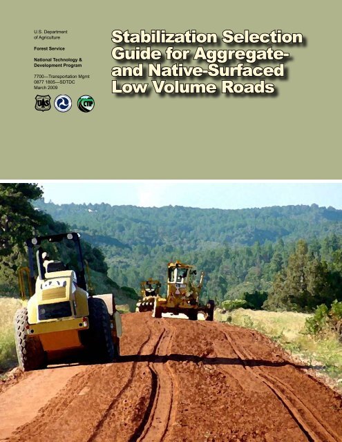
<strong>Stabilization</strong> <strong>Selection</strong><br />
<strong>Guide</strong> <strong>for</strong> <strong>Aggregate</strong>-<br />
and Native-Surfaced<br />
Low Volume Roads
Cover photo: Alan Anderson, Black Hills National Forest
<strong>Stabilization</strong> <strong>Selection</strong><br />
<strong>Guide</strong> <strong>for</strong> <strong>Aggregate</strong>-<br />
and Native-Surfaced<br />
Low-Volume Roads<br />
Maureen A. Kestler, Civil Engineer, Forest Service,<br />
San Dimas Technology & Development Center<br />
March 2009<br />
In<strong>for</strong>mation contained in this document has been developed <strong>for</strong> the guidance <strong>of</strong> employees <strong>of</strong> the<br />
U.S. <strong>Department</strong> <strong>of</strong> Agriculture (USDA) Forest Service, its contractors, and cooperating Federal and<br />
State agencies. The USDA Forest Service assumes no responsibility <strong>for</strong> the interpretation or use <strong>of</strong><br />
this in<strong>for</strong>mation by other than its own employees. The use <strong>of</strong> trade, firm, or corporation names is <strong>for</strong><br />
the in<strong>for</strong>mation and convenience <strong>of</strong> the reader. Such use does not constitute an <strong>of</strong>ficial evaluation,<br />
conclusion, recommendation, endorsement, or approval <strong>of</strong> any product or service to the exclusion <strong>of</strong><br />
others that may be suitable.<br />
The U.S. <strong>Department</strong> <strong>of</strong> Agriculture (USDA) prohibits discrimination in all its programs and activities<br />
on the basis <strong>of</strong> race, color, national origin, age, disability, and where applicable, sex, marital status,<br />
familial status, parental status, religion, sexual orientation, genetic in<strong>for</strong>mation, political beliefs,<br />
reprisal, or because all or part <strong>of</strong> an individual’s income is derived from any public assistance program.<br />
(Not all prohibited bases apply to all programs.) Persons with disabilities who require alternative<br />
means <strong>for</strong> communication <strong>of</strong> program in<strong>for</strong>mation (Braille, large print, audiotape, etc.) should contact<br />
USDA’s TARGET Center at (202) 720-2600 (voice and TDD). To file a complaint <strong>of</strong> discrimination,<br />
write USDA, Director, Office <strong>of</strong> Civil Rights, 1400 Independence Avenue, S.W., Washington, D.C.<br />
20250-9410, or call (800) 795-3272 (voice) or (202) 720-6382 (TDD). USDA is an equal opportunity<br />
provider and employer.
TABLE OF CONTENTS<br />
CHAPTER 1—OVERVIEW<br />
Introduction ................................................................................................ 1<br />
Purpose ...................................................................................................... 2<br />
Scope <strong>of</strong> <strong>Guide</strong> .......................................................................................... 2<br />
General In<strong>for</strong>mation and Background ........................................................ 5<br />
How To Use This <strong>Guide</strong> ............................................................................. 6<br />
CHAPTER 2—CHEMICAL STABILIZATION<br />
Selecting A Traditional Chemical Additive .................................................. 7<br />
Selecting A Nontraditional Chemical Additive .......................................... 13<br />
CHAPTER 3—MECHANICAL STABILIZATION<br />
Introduction .............................................................................................. 19<br />
Selecting a Mechanical <strong>Stabilization</strong> Technique ...................................... 19<br />
Background and Design Theory .............................................................. 24<br />
CHAPTER 4—CONSTRUCTION HINTS ................................................................ 33<br />
REFERENCES .................................................................................................... 37<br />
APPENdIx A—Definitions<br />
APPENdIx B—Traditional Chemical Stabilizers: Simplified method <strong>of</strong><br />
selecting and determining quantities (including FWHA 2005)<br />
APPENdIx C—Traditional Chemical Stabilizers: UASCE method <strong>of</strong><br />
selecting and determining quantities<br />
APPENdIx d—ASTM Soil Tests<br />
APPENdIx E—pH and Sulfate Tests<br />
APPENdIx F—Evaluation <strong>of</strong> Stabilizers<br />
APPENdIx G—Nontraditional Stabilizers (FHWA 2005)<br />
APPENdIx H—Mechanical <strong>Stabilization</strong> Techniques (FHWA 2005)<br />
APPENdIx I—Geosynthetics
ACKNOWLEdGMENTS This publication is the result <strong>of</strong> a partnership between the<br />
National Technology and Development Program <strong>of</strong> the Forest<br />
Service, U.S. <strong>Department</strong> <strong>of</strong> Agriculture and the U.S. <strong>Department</strong><br />
<strong>of</strong> Transportation Federal Highway administration (FHWA)<br />
Coordinated Federal Lands Highway Technology Improvement<br />
Program.<br />
We would like to acknowledge Pete Bolander and Douglas<br />
Scholen <strong>for</strong> providing the foundation from which this guide was<br />
developed, Gordon Keller <strong>for</strong> his recommendation <strong>of</strong> updating<br />
<strong>for</strong>mer selection guides to include recent developments and new<br />
in<strong>for</strong>mation on stabilizers that has come about during the past<br />
few years, Alan Yamada and Mike Mitchell <strong>for</strong> their guidance, and<br />
Charles Aldrich <strong>for</strong> providing helpful in<strong>for</strong>mation. The author also<br />
thanks Jeb Tingle at the U.S. Army Corps <strong>of</strong> Engineers Engineer<br />
Research and Development Center, Mike Voth and his colleagues<br />
at the Central Federal Lands, Minnesota Local Road Research<br />
Board, the Transportation Research Board, and also reviewers Bill<br />
Vischer, Pete Bolander, and Gordon Keller, those who provided<br />
photographs, the editors, and ever-so-many other Forest Service<br />
representatives who contributed toward the development <strong>of</strong> this<br />
updated stabilization guide.
CHAPTER ONE<br />
Overview<br />
Overview<br />
INTROdUCTION<br />
Soil stabilizers can be used to treat the upper several inches <strong>of</strong><br />
soil or aggregate surfaces <strong>of</strong> low-volume roads (LVRs) when<br />
the strength or other properties <strong>of</strong> the in-place soil do not meet<br />
the desired or required levels <strong>for</strong> anticipated traffic. Soil can<br />
be either modified or stabilized by many methods, including<br />
chemical, mechanical, thermal, and electrical (Danyluk 1986;<br />
Martel et al. unpublished). Modification is generally short term and<br />
includes benefits such as improvement in workability (expediting<br />
construction and saving time and money). <strong>Stabilization</strong> generally<br />
results in a longer term strength gain.<br />
q Chemical stabilization is achieved by mixing chemicals, such<br />
as cement, lime, fly ash, bitumen, or combinations <strong>of</strong> these<br />
materials, with soil to <strong>for</strong>m a stronger composite material.<br />
<strong>Selection</strong> <strong>of</strong> the type and percentage <strong>of</strong> additive is a function<br />
<strong>of</strong> the soil classification and the degree <strong>of</strong> improvement<br />
desired. Chemicals and/or emulsions can be used as:<br />
m Compaction aids to soils.<br />
m Binders and water repellents.<br />
m A means <strong>of</strong> modifying the behavior <strong>of</strong> clay to <strong>for</strong>m a<br />
stronger composite material.<br />
Chemical stabilization can aid in:<br />
m Dust control.<br />
m Water-erosion control.<br />
m Fixation and leaching control <strong>of</strong> both waste and recycled<br />
materials (Das 2000).<br />
q Mechanical modification/stabilization involves mixing (two<br />
or more soils to obtain a material <strong>of</strong> desired specification),<br />
draining, and/or compacting soil. Alternately, fibrous or<br />
other nonbiodegradable rein<strong>for</strong>cing materials, such as<br />
geosynthetics/geocomposites/fibers, can be mixed in or<br />
physically placed with the geomaterial to improve strength.<br />
q Thermal stabilization involves heating or freezing soil.<br />
m Heating the soil to 600 °C can irreversibly dehydrate or<br />
fuse soil particles.<br />
m Freezing can strengthen the soil by solidifying water<br />
content.<br />
q Electrical stabilization involves applying a direct electrical<br />
current to the soil. This causes water to migrate out <strong>of</strong> the<br />
soil to an electrode.<br />
1
CHAPTER ONE<br />
2<br />
This guide focuses on chemical and mechanical methods.<br />
Definitions used in conjunction with stabilization are provided in<br />
appendix A.<br />
PURPOSE The purpose <strong>of</strong> this guide is to facilitate the selection <strong>of</strong><br />
modification/stabilization agents and techniques <strong>for</strong> aggregatesurfaced<br />
and native/unsurfaced LVRs. The objective is to provide<br />
low-cost alternatives that reduce aggregate wear and loss, reduce<br />
road-surface maintenance (i.e., blading out ruts), and reduce the<br />
time period between major rehabilitation (i.e., between adding new<br />
aggregate or the total reconditioning <strong>of</strong> the road pavement).<br />
This guide provides in<strong>for</strong>mation on available stabilizing agents,<br />
appropriate conditions <strong>for</strong> use, selection procedures, quantity<br />
determination, and contact in<strong>for</strong>mation <strong>for</strong> manufacturers/suppliers.<br />
Emphasis is on the modification/stabilization <strong>of</strong> existing in-place<br />
road surface materials, but many <strong>of</strong> the methods can be used in the<br />
construction <strong>of</strong> new roads. Construction procedures <strong>for</strong> application<br />
are also presented.<br />
The intended audience includes road managers, engineers,<br />
and technicians involved in road maintenance, construction,<br />
and reconstruction. Those involved in trail maintenance and<br />
construction also may find the guide beneficial, as stabilizers<br />
used on trails, particularly accessible trails, help provide a<br />
smooth, durable surface. In<strong>for</strong>mation on the use <strong>of</strong> synthetics<br />
<strong>for</strong> trails can be found in the Forest Service, U.S. <strong>Department</strong> <strong>of</strong><br />
Agriculture, publication “Geosynthetics <strong>for</strong> Trails in Wet Areas” by<br />
Groenier (2008). In<strong>for</strong>mation on accessible trails is provided in<br />
another Forest Service publication, “Soil Stabilizers on Universally<br />
Accessible Trails” (Bergmann 2000).<br />
SCOPE OF GUIdE This guide focuses primarily on chemical and mechanical<br />
methods. It serves as an updated sequel to two reports prepared<br />
in the 1990s, “Non-Standard Stabilizers” (Scholen 1992) and<br />
“<strong>Stabilization</strong> with Standard and Nonstandard Stabilizers” (Bolander<br />
1995), and incorporates applicable tables from the “Surfacing<br />
<strong>Selection</strong> <strong>Guide</strong>” recently developed by the U.S. <strong>Department</strong> <strong>of</strong><br />
Transportation, Federal Highway Administration (FHWA), Central<br />
Lands Federal Highway Division (FHWA 2005), and tables from the<br />
Transportation Research Board (TRB) (Petry and Sobhan 2005).<br />
The guide also incorporates procedures from the U.S. Army Corps<br />
<strong>of</strong> Engineers (USACE), and reflects discussions with engineers<br />
and contractors, manufacturers and suppliers, and individuals from<br />
other agencies with stabilization expertise.
Traditional and Nontraditional<br />
Modification/Stabilizer Agents<br />
Overview<br />
Traditional Chemical<br />
Stabilizers Traditional chemical techniques include:<br />
q Cement (generally used as a base-course treatment and not<br />
as a surface treatment, but included because it is one <strong>of</strong> the<br />
standard “traditional” stabilizers).<br />
q Lime.<br />
q Fly ash.<br />
q Bituminous materials.<br />
q Combinations <strong>of</strong> the above.<br />
Two procedures <strong>for</strong> selecting types and quantities <strong>of</strong> these products<br />
are provided.<br />
Nontraditional Stabilizers Nontraditional stabilizers are typically grouped into seven<br />
categories:<br />
q Chlorides (chlorides, salts, calcium chloride, magnesium<br />
chloride, sodium chloride).<br />
q Clay additives (clay additives, clay, filler, bentonite,<br />
montmorillonite).<br />
q Electrolyte emulsions (electrolyte stabilizers, ionic stabilizers,<br />
electrochemical stabilizers, acids).<br />
q Enzymatic emulsions (enzymatic emulsions, enzymes).<br />
q Lignosulfonates (lignosulfonates, lignin, lignin sulfate, lignin<br />
sulfides).<br />
q Synthetic-polymer emulsions (synthetic-polymer emulsions,<br />
polyvinyl acetate, vinyl acrylic).<br />
q Tree-resin emulsions (tree-resin emulsions, tall-oil<br />
emulsions, pine-tar emulsions).<br />
Although the guide does not provide a comparable step-bystep<br />
procedure <strong>for</strong> selecting nontraditional stabilizers, general<br />
in<strong>for</strong>mation tables are provided to help select a nontraditional<br />
stabilizer.<br />
Mechanical Stabilizers The guide also includes in<strong>for</strong>mation on mechanical modification/<br />
stabilizing methods. These range from more conventional<br />
compaction and geosynthetics to less conventional woodchips and<br />
mats.<br />
3
CHAPTER ONE<br />
Other Categories Many categories are included under the topic <strong>of</strong> stabilization.<br />
However, because <strong>of</strong> the broadness <strong>of</strong> the following three<br />
categories, the reader will be referred to other specialty guides and<br />
design programs <strong>for</strong> guidance and further details.<br />
Dust Palliatives This guide includes chemicals that serve as both dust suppressants<br />
and stabilizers, but does not discuss chemicals that are used<br />
exclusively <strong>for</strong> dust control. Although dust control is a side benefit<br />
<strong>of</strong> many <strong>of</strong> the stabilization techniques described, if one’s primary<br />
objective is to control dust, the reader is referred to “Dust Palliative<br />
<strong>Selection</strong> and Application <strong>Guide</strong>” (Bolander and Yamada 1999),<br />
“Chemical Additives <strong>for</strong> Dust Control, What We Have Used and<br />
What We Have Learned” (Bolander 1997), and “Best Practices<br />
<strong>for</strong> Dust Control on <strong>Aggregate</strong> Roads” (Johnson and Olson 2009).<br />
Additional in<strong>for</strong>mation is available on the USACE Web site, https://<br />
transportation.wes.army.mil/triservice/fileslist.aspx?GroupId=2<br />
(U.S. Army Corps <strong>of</strong> Engineers), which provides a comprehensive<br />
list <strong>of</strong> manuals, videos, reports, photos, and PowerPoint<br />
presentations on various aspects <strong>of</strong> dust control including:<br />
q Chemical Dust Abatement <strong>for</strong> Desert Roads.<br />
q Chemical Dust Abatement <strong>for</strong> Roads in Temperate Climate.<br />
q Dust Abatement Equipment.<br />
4<br />
Additional publications on dust palliatives are available from<br />
the 2008 Road Dust Management Practices and Future Needs<br />
Conference in San Antonio, Texas, November 2008, http://www.<br />
meetingsnorthwest.com/DustConference.htm<br />
Stabilizers <strong>for</strong> Paved Roads Although stabilization can be used to improve foundation layers<br />
supporting a paved road—thereby reducing the required structural<br />
thickness—the design <strong>of</strong> a stabilized subgrade or base layers in<br />
conjunction with a paved surface is beyond the scope <strong>of</strong> this report.<br />
Numerous publications and pavement-design programs provide<br />
guidance on selection and design <strong>of</strong> stabilized layers <strong>for</strong> paved<br />
roads (<strong>Department</strong> <strong>of</strong> the Army 1994; FHWA 2005).<br />
For bituminous surface treatments, there is a vast list <strong>of</strong><br />
publications and guides by Local Technical Assistance Programs<br />
(LTAPs) or Technology Transfer (T 2 ) Centers, State <strong>Department</strong>s<br />
<strong>of</strong> Transportation, such as the “Minnesota Sealcoat Handbook”<br />
(Wood 2006), and the military. Additional publications include those<br />
by FHWA (2005), Yamada (1999), Bolander et al. (1999), and<br />
Niezgoda et al. (2000).
Overview<br />
Deep Mixing and Grouting Chemical stabilization also includes deep mixing and grouting.<br />
They are not covered in this guide; the reader is referred to outside<br />
references. (ASCE 2004; Bushman et al. 2004; Karol 2003; Warner<br />
2004).<br />
GENERAL INFORMATION<br />
ANd BACKGROUNd Much published literature on stabilization techniques <strong>for</strong> unpaved<br />
road surfacing is currently available. However, most publications<br />
are on specific methods—such as lime stabilization—or specific<br />
aspects <strong>of</strong> geosynthetics. Some general guides do exist, but even<br />
they are generally limited to selecting and designing <strong>for</strong> a traditional<br />
chemical treatment, or designing <strong>for</strong> a geosynthetic installation.<br />
One must generally have a slight idea <strong>of</strong> what type <strong>of</strong> stabilization<br />
task he or she wishes to pursue, then select and design from that<br />
starting point.<br />
A large-scale project to develop a decision tool <strong>for</strong> selecting the<br />
most cost-effective solution <strong>for</strong> a given site (road) and operating<br />
conditions (type <strong>of</strong> traffic, intensity, season <strong>of</strong> use, etc.) is ongoing<br />
at the time this guide is being written. The Web site http://carrlo.<br />
fsg.ulaval.ca/ is currently in French, but numerous publications in<br />
English are scheduled over the 5-year duration <strong>of</strong> the program and<br />
will be referenced on the Web site. A summary <strong>of</strong> the evaluation<br />
program (Legere 2007) follows:<br />
“Various studies have been conducted to understand the<br />
general behavior and improve the per<strong>for</strong>mance <strong>of</strong> unpaved<br />
roads. However, most <strong>of</strong> the research conducted is only<br />
applicable in specific working conditions. After consultation<br />
with many unpaved road managers, designers, and several<br />
key players in this area, a consensus was made on the need<br />
to develop a guide <strong>of</strong> adapted and economic solutions <strong>for</strong><br />
the construction, rehabilitation and management techniques<br />
<strong>for</strong> unpaved roads. This will take into consideration all <strong>of</strong> the<br />
characteristics <strong>of</strong> a given project in order to keep unpaved<br />
road surfaces per<strong>for</strong>ming, safe and smooth. It is in that<br />
perspective that Université Laval in Quebec city, Canada, with<br />
financial support from the Natural Sciences and Engineering<br />
Research Council <strong>of</strong> Canada, as well as a group <strong>of</strong> several<br />
partners from different interests such as FPInnovations –<br />
FERIC division, Ciment Saint-Laurent, Bitume-Québec,<br />
Junex, Les Entreprises Bourget, the Ministère des transports<br />
du Québec, and the Société de développement de la Baie-<br />
James, has undertaken in 2005 a major research project to<br />
5
CHAPTER ONE<br />
fulfill the needs in this field. The research project is identified<br />
as the CARRLo project, which stands <strong>for</strong> Chemins d’Accès<br />
aux Ressources et Routes Locales. To date, most testing<br />
has been conducted in the laboratory, but field tests are next<br />
scheduled, much <strong>of</strong> which includes test equipment as shown<br />
in figure 1.1.”<br />
Those seeking guidance <strong>for</strong> selecting stabilizers <strong>for</strong> surfacing<br />
unpaved roads are encouraged to seek publications from this<br />
ef<strong>for</strong>t as the program progresses, as well as other references cited<br />
throughout this guide.<br />
Figure 1.1—CARRLo test program simulator (Glen Legere).<br />
HOW TO USE THIS GUIdE After a general introduction to stabilization in chapter 1, chapter 2<br />
provides a discussion on traditional and nontraditional stabilizers.<br />
Corresponding appendixes show the procedure <strong>for</strong> selection and<br />
determination <strong>of</strong> traditional stabilizers, and include tables with<br />
general in<strong>for</strong>mation on nontraditional chemical additives. The tables<br />
provide specific products, suppliers, and contact in<strong>for</strong>mation.<br />
6<br />
Chapter 3 and corresponding appendixes cover mechanical<br />
stabilization. Several techniques are discussed, and design<br />
procedures, in<strong>for</strong>mation tables, and decision tables are provided.<br />
Chapter 4 and the corresponding appendixes discuss construction<br />
hints. Construction topics, such as materials, equipment, placement<br />
processes, and weather restrictions, are included.
CHAPTER TWO<br />
Chemical <strong>Stabilization</strong><br />
Chemical <strong>Stabilization</strong><br />
SELECTING A TRAdITIONAL CHEMICAL AddITIVE<br />
Consider these factors when selecting a chemical stabilizer:<br />
q Type <strong>of</strong> soil to be stabilized.<br />
q Purpose <strong>of</strong> the stabilized layer.<br />
q Type <strong>of</strong> soil improvement desired (modification or<br />
stabilization/improvement <strong>of</strong> strength characteristics).<br />
q Required strength and durability <strong>of</strong> the stabilized layer.<br />
q Cost.<br />
q Environmental conditions.<br />
Traditional chemical stabilizers include:<br />
q Cement.<br />
q Lime.<br />
q Fly ash.<br />
q Bituminous materials.<br />
q Combinations <strong>of</strong> the above.<br />
<strong>Selection</strong> Process<br />
Two procedures <strong>for</strong> selecting a traditional stabilizer are provided by<br />
table 2.1.<br />
Both methods require soil testing. The first method requires a<br />
gradation and Atterberg limit test; the second method requires some<br />
additional testing as noted in the procedure. General in<strong>for</strong>mation on<br />
each stabilizer follows table 2.1.<br />
Follow the USACE procedure to optimize the type and quantity<br />
<strong>of</strong> stabilizer required to achieve the desired characteristic and to<br />
minimize cost. The reason to do this is because there is generally<br />
more than one stabilizer applicable <strong>for</strong> any one soil type. However,<br />
based on features, such as soil granularity, plasticity, or texture,<br />
some stabilizers are more applicable to certain soils than others<br />
(Army 1994). The USACE procedure enables optimal selection<br />
<strong>of</strong> the right stabilizer <strong>for</strong> the particular soil, and optimizes the<br />
cost by determining the minimal quantity <strong>of</strong> stabilizer required to<br />
achieve the desired strength. The USACE procedure also provides<br />
quantities <strong>for</strong> modification. The simplified procedure is significantly<br />
easier; it just requires looking at tables <strong>for</strong> the known gradations<br />
and Atterberg limits. However, the quantities <strong>for</strong> modification will still<br />
require looking at tables <strong>for</strong> the USACE procedure.<br />
7
CHAPTER TWO<br />
Table 2.1—Two procedures <strong>for</strong> selecting a traditional chemical stabilizing agent.<br />
8<br />
1. Simplified Procedure or 2. Simplified USACE Procedure<br />
Step 1—Determine the type <strong>of</strong> material present<br />
(classify soil and/or aggregate). Conduct a grain<br />
size distribution and Atterberg limits tests (select<br />
either the ASTM or the AASHTO test from appendix<br />
table D.1).<br />
Step 2—Determine the objective (stabilization<br />
or modification). If modification, it is recommended<br />
to use method 2, or at least look at the<br />
USACE tables <strong>of</strong> method 2.<br />
Step 3—Select a stabilizing agent: Several candidate<br />
stabilizers can be selected using various<br />
combinations <strong>of</strong> appendix figure B.1 and appendix<br />
tables B.1 through B.4. The candidate stabilizers<br />
can be narrowed down to one by using<br />
multiple tables, including in<strong>for</strong>mation pertaining<br />
to each stabilizer in table B.4. Or one could use<br />
figure C.1 with table C.1.<br />
Step 4—Determine the amount required using<br />
recommendations in appendix table B.3 or B.4<br />
and by checking with local suppliers or manufacturers.<br />
Step 5—Select one or two alternatives <strong>for</strong> further<br />
evaluation.<br />
Step 6—Determine the expected costs <strong>of</strong> the<br />
various alternatives and determine if cost effective;<br />
appendix table B.4 may provide a rough<br />
idea, however, calling local suppliers and using<br />
local labor estimates is recommended <strong>for</strong> final<br />
selection.<br />
Step 1—Determine the type <strong>of</strong> material present<br />
(classify soil and/or aggregate). Conduct a<br />
grain size distribution and Atterberg limits tests<br />
(select either the ASTM or the AASHTO test<br />
from appendix table D.1). Further testing may<br />
be required as directed by the table.<br />
Step 2—Determine the objective (stabilization<br />
or modification). If modification is required, continue<br />
with this procedure as modification quantities<br />
are provided.<br />
Step 3—Select a stabilizing agent: appendix<br />
figure C.1 (a soil-gradation triangle) and appendix<br />
table C.1 are used, in combination, to<br />
determine candidate stabilizers. Accompanying<br />
instructions are provided immediately above<br />
figure C.1. Added general in<strong>for</strong>mation on each<br />
traditional stabilizer follows this table.<br />
Step 4—Determine the amount using the<br />
procedure in appendix tables C.2 (a-f). These<br />
are separate tables that provide instructions <strong>for</strong><br />
each chemical stabilizer.<br />
Step 5—Select one or two alternatives <strong>for</strong> further<br />
evaluation (using the simplified or USACE<br />
method).<br />
Step 6—Determine the expected costs <strong>of</strong> the<br />
various alternatives and determine if cost effective;<br />
appendix table B.4 may provide a rough<br />
idea, however, calling local suppliers and using<br />
local labor estimates is recommended.
Traditional Chemical<br />
Stabilizing Agents<br />
Chemical <strong>Stabilization</strong><br />
Portland Cement<br />
(Note: Do not use a cementstabilized<br />
material <strong>for</strong> surfacing) Adding cement to soil increases soil strength, decreases<br />
compressibility, reduces swell potential, and increases durability.<br />
It is similar to lime, but has pozzolanic materials that cause rapid<br />
hardening, resulting in a solid, bound, impermeable layer. Cementstabilized<br />
soils are typically used as a stabilized subgrade or<br />
road base (figure 2.1), but not as surfacing (except possibly <strong>for</strong><br />
low-speed roads and parking lots) primarily because the material<br />
becomes brittle and cracks under traffic loading. Shrinkage cracks<br />
in the surface can be avoided if unconfined strengths are kept<br />
below 700 pounds per square inch. Curing <strong>of</strong> a soil-cement mixture<br />
is essential (the surface must be kept wet <strong>for</strong> the first 7 days <strong>of</strong><br />
curing), at a minimum, by either periodically applying water or by<br />
sealing the surface with a fog seal or similar seal.<br />
Fine-grained soils can be stabilized with cement, and sandy soils<br />
are readily stabilized with cement; but the major application <strong>of</strong> soil<br />
cement is in bases and subbases <strong>of</strong> secondary roads. Cement<br />
should not be used <strong>for</strong> soils with high organic content or soils<br />
that contain sulfates. Extreme caution must be exercised if<br />
used in areas subject to seasonal freezing.<br />
Soils can be stabilized by several types <strong>of</strong> cement: Type I (normal),<br />
Type Ia (air entraining), Type II (greater sulfate resistance <strong>for</strong> a<br />
similar price to Types I and Ia), and Type III (high early strength,<br />
with a finer particle size and different chemical composition).<br />
Types I or II are more typically used <strong>for</strong> stabilizing, with Type II<br />
perhaps being used the most. Chemical- and physical-property<br />
specifications <strong>for</strong> Portland cement are available in ASTM C 150.<br />
In<strong>for</strong>mation on testing and determining quantities using the USACE<br />
method is available in appendix table C.2a. Additional details<br />
on construction, safety, environmental concerns, cost, etc. are<br />
provided in respective sections <strong>of</strong> appendix table B.4 (FHWA 2005).<br />
Section 6.3 <strong>of</strong> the FHWA Web site http://www.cflhd.gov/<br />
techDevelopment/completed_projects/pavement/context-roadwaysurfacing/#supplement<br />
(FHWA 1995), provides additional photos.<br />
9
CHAPTER TWO<br />
10<br />
2.1b—Water<br />
truck (Charles<br />
Miller, Porter,<br />
Maine).<br />
2.1a—Cement<br />
application.<br />
Figure 2.1c—<br />
Compacting<br />
(Charles Miller,<br />
Porter, Maine).<br />
Figure 2.1—Cement, a traditional stabilizing agent. Generally, cement is<br />
used <strong>for</strong> the base and not the surface.
Chemical <strong>Stabilization</strong><br />
Lime<br />
(Lime stabilized soil is rarely<br />
used as a surfacing material) Adding lime to soil generally decreases soil density, decreases<br />
plasticity, improves workability, and reduces volume-change<br />
characteristics. It may or may not improve strength characteristics.<br />
Strength characteristics depend on the soil type. It is used primarily<br />
to treat fine-grained soils.<br />
Common <strong>for</strong>ms <strong>of</strong> lime include hydrated high-calcium lime,<br />
monohydrated dolomitic lime, calcitic quicklime, and dolomitic<br />
quicklime. The design criteria presented here are <strong>for</strong> hydrated<br />
quicklime, the most commonly used <strong>for</strong>m <strong>of</strong> lime. Design quicklime<br />
quantities would be 75 percent <strong>of</strong> design hydrated lime quantities.<br />
In contrast to Portland cement, lime cementation takes place slowly.<br />
Like cement, a surface coat <strong>of</strong> a different material is typically<br />
applied because <strong>of</strong> the poor resistance to abrasive action<br />
<strong>of</strong> continued traffic. However, if there is no surfacing, periodic<br />
blading does remove de<strong>for</strong>mations without adversely affecting the<br />
lime-soil reaction.<br />
In<strong>for</strong>mation on testing and determining quantities using the USACE<br />
method is available in appendix table C.2b. Additional details<br />
on construction, safety, environmental concerns, cost, etc. are<br />
provided in respective sections <strong>of</strong> appendix table B.4 (FHWA 2005).<br />
Photos showing lime being used as a stabilizing agent are<br />
available in section 6.2 <strong>of</strong> the FHWA Web site http://www.cflhd.gov/<br />
techDevelopment/completed_projects/pavement/context-roadwaysurfacing/#supplement<br />
(FHWA 1995).<br />
Lime Fly Ash and<br />
Lime-Cement Fly Ash<br />
(Note: Do not use a cementstabilized<br />
material <strong>for</strong> surfacing) Coarse-grained soils with little to no fines can be stabilized using<br />
lime fly ash or lime-cement fly ash. Like cement, fly ash is typically<br />
used to stabilize the subbase or subgrade, and should not be used<br />
<strong>for</strong> surfacing materials. Fly ash (or coal ash) is a mineral residue<br />
from the combustion <strong>of</strong> pulverized coal, and is transported from the<br />
boilers by flue gases. When fly ash is mixed with lime and water, a<br />
cemented mass capable <strong>of</strong> withstanding high compressive stresses<br />
is <strong>for</strong>med.<br />
Fly ash requires good mixing, compaction immediately after mixing,<br />
and proper water <strong>for</strong> curing.<br />
11
CHAPTER TWO<br />
12<br />
In<strong>for</strong>mation on testing and determining quantities using the USACE<br />
method is available in appendix table C.2c.<br />
A photo showing fly ash being used as a stabilizing agent is<br />
available in section 6.1 <strong>of</strong> the FHWA Web site http://www.cflhd.gov/<br />
techDevelopment/completed_projects/pavement/context-roadwaysurfacing/#supplement<br />
(FHWA 1995).<br />
Bitumen/Asphalt <strong>Stabilization</strong> using asphalt differs significantly from stabilization<br />
using lime or cement. The primary mechanisms <strong>for</strong> cohesive and<br />
noncohesive materials are (1) waterpro<strong>of</strong>ing and (2) waterpro<strong>of</strong>ing<br />
and adhesion, respectively. Fine-grained materials are coated<br />
with asphalt, thereby slowing down the penetration <strong>of</strong> water,<br />
which would otherwise lead to reduced strength. Coarse-grained<br />
materials are similarly coated/waterpro<strong>of</strong>ed, but the particles also<br />
adhere to the asphalt, and the asphalt acts as a binder.<br />
In contrast to lime and cement, freeze-thaw and wet-dry durability<br />
tests are not applicable <strong>for</strong> asphalt-stabilized mixtures.<br />
Types <strong>of</strong> bituminous-stabilized soils include sand bitumen, gravel or<br />
crushed-aggregate bitumen, and bitumen lime (lime is added to the<br />
soil-bitumen mix when the soil’s plasticity index is higher than 10).<br />
In<strong>for</strong>mation on testing and determining quantities using the USACE<br />
method is available in appendix table C.2d.<br />
Photos showing bituminous surface treatments are available<br />
in chapter 1 <strong>of</strong> the FHWA Web site http://www.cflhd.gov/<br />
techDevelopment/completed_projects/pavement/context-roadwaysurfacing/#supplement<br />
(FHWA 1995).<br />
Lime-Cement and<br />
Lime-Bitumen Stabilizers can be used in combination to enable one stabilizer to<br />
compensate <strong>for</strong> the lack <strong>of</strong> effectiveness <strong>of</strong> another in treating a<br />
particular characteristic <strong>of</strong> a soil. For instance, Portland cement or<br />
asphalt cannot be mixed with plastic clays. However, adding lime<br />
makes the soil friable, in turn enabling the cement or asphalt to be<br />
mixed readily.<br />
In<strong>for</strong>mation on testing and determining quantities using the USACE<br />
method is available in appendix table C.2e.
Chemical <strong>Stabilization</strong><br />
SELECTING A<br />
NONTRAdITIONAL AddITIVE<br />
Introduction The market is becoming increasingly populated by alternative<br />
nontraditional stabilization products, such as concentrated liquid<br />
stabilizers and waste byproducts. This is because <strong>of</strong> the potentially<br />
lengthy cure times and the large quantities <strong>of</strong> additive required <strong>for</strong><br />
the desired strength gain <strong>for</strong> most traditional chemical stabilizing<br />
agents, as well as adverse chemical reactions <strong>for</strong> a few traditional<br />
chemical stabilizing agents (in sulfate-bearing soils <strong>for</strong> cement,<br />
lime, and fly ash).<br />
Nontraditional stabilizers are typically grouped into seven<br />
categories:<br />
q Chlorides (chlorides, salts, calcium chloride, magnesium<br />
chloride, sodium chloride).<br />
q Clay additives (clay additives, clay, filler, bentonite,<br />
montmorillonite).<br />
q Electrolyte emulsions (electrolyte stabilizers, ionic stabilizers,<br />
electrochemical stabilizers, acids).<br />
q Enzymatic emulsions (enzymatic emulsions, enzymes).<br />
q Lignosulfonates (lignosulfonates, lignin, lignin sulfate, lignin<br />
sulfides).<br />
q Synthetic-polymer emulsions (synthetic-polymer emulsions,<br />
polyvinyl acetate, vinyl acrylic).<br />
q Tree-resin emulsions (tree-resin emulsions, tall-oil emulsions,<br />
pine-tar emulsions).<br />
Appendix table G.1 (FHWA 2005) provides a comprehensive<br />
overview <strong>of</strong> nontraditional additives. However many <strong>of</strong> these<br />
products are advertised as (1) requiring lower additive quantities<br />
and reduced cure times, and (2) yielding higher material strengths<br />
and superior durability. It should be noted that limited independent<br />
research has been completed to distinguish between products<br />
that deliver such enhanced per<strong>for</strong>mance and those that do not,<br />
or only partially do (Tingle and Santoni 2003). Comparisons and<br />
subsequent selection <strong>of</strong> products can there<strong>for</strong>e be subjective and<br />
sometimes complicated.<br />
13
CHAPTER TWO<br />
14<br />
1. By nature, some stabilizing products per<strong>for</strong>m well in certain<br />
soil types or environments, but per<strong>for</strong>m poorly in others.<br />
2. Because most <strong>of</strong> the recently introduced products are<br />
proprietary, mechanisms <strong>of</strong> stabilization are generally<br />
unknown.<br />
3. Marketing strategies yield frequent discontinuity in brand<br />
names; this in turn, results in a lack <strong>of</strong> product history and<br />
user familiarity.<br />
Some stabilizers are literally resting on the laurels <strong>of</strong> the<br />
manufacturer’s claims. Procedures <strong>for</strong> the evaluation <strong>of</strong> a product<br />
are generally developed by individual agencies using the selected<br />
test standards in appendix F. Occasionally a summary <strong>of</strong> known<br />
evaluations by other agencies will be provided by the product<br />
manufacturer, as will recommendations <strong>for</strong> conducting in-house<br />
product evaluations, if desired.<br />
Evaluation and selection <strong>of</strong><br />
a nontraditional stabilizer If a nontraditional stabilizer is going to be used, one should<br />
consult appendix table G.1 (FHWA 2005) <strong>for</strong> suggested soil types,<br />
environments, etc. Some preliminary tests should be conducted to<br />
determine if the candidate stabilizer will work <strong>for</strong> the specific soil<br />
type. Table 2.2 lists tables taken from the TRB’s circular “Evaluation<br />
<strong>of</strong> Chemical Stabilizers, State <strong>of</strong> the Practice Report” (Petry and<br />
Sobhan 2005), which in turn lists applicable test protocols from<br />
which to choose <strong>for</strong> conducting evaluations.<br />
Table 2.2—Tables that list standardized tests from which one can choose<br />
<strong>for</strong> conducting an evaluation.<br />
Appendix table To test:<br />
Table D-1 Untreated soil<br />
Table F-1 Stabilizer<br />
Table F-2 Treated soil<br />
All tests certainly need not be conducted, just those on a limited<br />
number <strong>of</strong> desired properties to be altered (e.g., gradation,<br />
Atterberg limits, unconfined compression <strong>for</strong> strength). Based<br />
on the test results, an appropriate chemical stabilizer, which will<br />
improve this property, can be determined.
Chemical <strong>Stabilization</strong><br />
When considering a stabilizing agent, it might be beneficial to<br />
consult with someone who has used that product under as similar<br />
conditions as possible/practical (environment, soil type, anticipated<br />
traffic level, etc.). If time allows, try to conduct full-scale test<br />
sections in the field to enable a full-scale evaluation <strong>of</strong> per<strong>for</strong>mance<br />
in the project environment. Ideally, these tests should be done a<br />
year in advance to observe the per<strong>for</strong>mance over the passage <strong>of</strong><br />
time and seasons. Low application rates will provide modification<br />
and higher amounts will provide stabilization. It may be necessary<br />
to provide higher application rates than recommended by the<br />
manufacturer to make the product work.<br />
One major difference that should be noted be<strong>for</strong>e selecting a<br />
nontraditional stabilizing agent—or <strong>for</strong> that matter prior to choosing<br />
any stabilizing agent—is its ability to reactivate. Some products set<br />
up and cannot be reactivated with normal ripping and reshaping<br />
with routine maintenance equipment. Examples include traditional<br />
stabilizing agents, such as Portland cement, lime, and asphalt/<br />
emulsions, as well as some nontraditional stabilizing agents such<br />
as nontraditional enzymatic emulsions including EMC SQUARED<br />
(EMC 2 ). In contrast, nontraditional chlorides or clays (such as<br />
bentonite) allow reactivation.<br />
If reactivation is desired, an agent such as calcium chloride or<br />
magnesium chloride is recommended. The Forest Service has<br />
conducted fairly comprehensive studies on the chlorides but in<br />
specific locations; the reader is referred to Monlux and Mitchell<br />
(2006, 2007). Figure 2.2 shows the use <strong>of</strong> chlorides <strong>for</strong> this Forest<br />
Service evaluation.<br />
Conversely, if a permanent solid-wear surface (that cannot be<br />
recrowned if improperly crowned when the stabilizing agent was<br />
placed) is desired, an enzymatic emulsion should be evaluated<br />
and considered. The Ozark-St. Francis National Forest has used<br />
EMC 2 and Roadbond En1 extensively with much success. To the<br />
observer, a road stabilized with these products looks no different<br />
than an unstabilized gravel road (figure 2.3).<br />
An additional publication on nontraditional additives is available by<br />
Bolander (1999).<br />
15
CHAPTER TWO<br />
16<br />
Figure 2.2b—Mixing<br />
dry chloride.<br />
Figure 2.2d—Blade<br />
mixing dry chloride.<br />
Figure 2.2a—Dry<br />
chloride application.<br />
Figure 2.2c—<br />
Liquid chloride<br />
application.<br />
Figure 2.2—Calcium and magnesium chloride, Forest Service project<br />
(Steve Monlux and Mike Mitchell).
Figure 2.3b—<br />
Finished surface.<br />
Chemical <strong>Stabilization</strong><br />
Figure 2.3a—<br />
Spreading and<br />
compacting.<br />
Figure 2.3c—<br />
Close-up <strong>of</strong><br />
finished surface.<br />
Figure 2.3—EMC squared, an enzymatic emulsion, Black Hills National<br />
Forest (Alan Anderson, R2).<br />
17
CHAPTER TWO<br />
18<br />
A variety <strong>of</strong> additional photos <strong>of</strong> nontraditional stabilizing agents is<br />
available in chapter 5 <strong>of</strong> the FHWA Web site http://www.cflhd.gov/<br />
techDevelopment/completed_projects/pavement/context-roadwaysurfacing/#supplement<br />
(FHWA 1995). Sections (<strong>of</strong> that Web site)<br />
with photos <strong>of</strong> specific categories include:<br />
FHWA section 5.1 – Chlorides.<br />
FHWA section 5.2 – Clay Additives.<br />
FHWA section 5.3 – Electrolyte Emulsions.<br />
FHWA section 5.4 – Enzymatic Emulsions.<br />
FHWA section 5.5 – Lignosulfates.<br />
FHWA section 5.6 – Organic-Petroleum Emulsions.<br />
FHWA section 5.7 – Synthetic-Polymer Emulsions.<br />
FHWA section 5.8 – Tree-Resin Emulsions.
CHAPTER THREE<br />
Mechanical <strong>Stabilization</strong><br />
Mechanical <strong>Stabilization</strong><br />
INTROdUCTION<br />
Mechanical stabilization covers everything from compacting<br />
and blending soils, to incorporating any <strong>of</strong> a vast assortment<br />
<strong>of</strong> conventional geosynthetics, to using (installing, placing,<br />
incorporating, blending) less conventional materials, such as<br />
woodchips, sawdust, and woodmats, to aid in meeting the required<br />
strength. This section references tables that provide in<strong>for</strong>mation<br />
on conventional and less conventional mechanical-stabilization<br />
techniques.<br />
SELECTING A MECHANICAL-STABILIZING TECHNIqUE<br />
Compaction and geosynthetics are the most widely used and<br />
accepted mechanical-stabilizing techniques. Appendix table H.1<br />
provides a comprehensive listing <strong>of</strong> issues and concerns, such<br />
as serviceability, safety, environment, and cost <strong>for</strong> three selected<br />
mechanical-stabilization categories: cellular confinement, fiber<br />
rein<strong>for</strong>cement, and geotextile/geogrid rein<strong>for</strong>cement (FHWA 1995).<br />
The chapter also briefly discusses several less conventional<br />
and far less used techniques. Appendix table H.2 is a decision<br />
matrix resulting from a military test in which many <strong>of</strong> these less<br />
conventional expedient stabilization techniques were evaluated<br />
(Kestler et al. 1999). Although military and <strong>for</strong>est roads may differ<br />
in purpose, some <strong>of</strong> these stabilizing surfaces could be used<br />
within the Forest Service <strong>for</strong> temporary roads over s<strong>of</strong>t ground and<br />
localized sections requiring stabilization. The emphasis here is on<br />
localized sections; the surfaces are generally not recommended<br />
as a stabilization technique <strong>for</strong> a road <strong>of</strong> any length. The table<br />
provides rankings on factors such as traction, equipment required<br />
<strong>for</strong> construction, life expectancy, ease <strong>of</strong> walking/foot traffic, etc.<br />
Ashmawy et al. (2006) provide a comprehensive assessment <strong>of</strong><br />
various recycled materials that can be used to stabilize marginal<br />
soils in Florida. Such materials include scrap tires and slag because<br />
<strong>of</strong> their relatively low cost and desirable engineering properties.<br />
These less conventional techniques may provide viable alternatives<br />
to more costly standard stabilization techniques, but require sound<br />
engineering judgment and good management practices.<br />
Compaction<br />
Compaction is the most basic <strong>of</strong> the mechanical-stabilization<br />
techniques. Proper compaction is essential. It increases density<br />
thus lowering the potential <strong>of</strong> increased moisture content, even in<br />
case <strong>of</strong> saturation. Both increased density and decreased moisture<br />
content potentially increase strength.<br />
19
CHAPTER THREE<br />
Geosynthetics The term geosynthetics is defined as a set <strong>of</strong> materials used to<br />
improve the per<strong>for</strong>mance <strong>of</strong> grounds or foundations in geotechnical<br />
engineering. Thus incorporating any <strong>of</strong> an extensive variety<br />
<strong>of</strong> geosynthetics can stabilize a soil (figure 3.1). Excluding<br />
compacting, using a geosynthetic is probably the most widely<br />
accepted mechanical-stabilization technique.<br />
20<br />
Figure 3.1b—Geonets<br />
(GSI 2003).<br />
Figure 3.1—Geosynthetics.<br />
Figure 3.1a—<br />
Geogrids (GSI 2003).<br />
Figure 3.1c—<br />
Geomembranes (GSI<br />
2003).
Figure 3.1e—<br />
Polymeric Geogrid<br />
used on a slip-repair<br />
project on a paved<br />
road in the developed<br />
recreation area,<br />
Wayne NF (Cindy<br />
Henderson).<br />
Figure 3.1g—<br />
Geosynthetic installation<br />
at York Pond Road, White<br />
Mountain NF.<br />
Figure 3.1—Geosynthetics<br />
(continued).<br />
Mechanical <strong>Stabilization</strong><br />
Figure 3.1d—<br />
Geocomposites (GSI<br />
2003).<br />
Figure 3.1f—<br />
Geosynthetic used<br />
immediately beneath<br />
asphalt.<br />
21
CHAPTER THREE<br />
22<br />
Figure 3.1i—Be<strong>for</strong>e<br />
Geoblock: Cycle trail<br />
hardening project,<br />
Francis Marion NF<br />
(Scott Groenier).<br />
Figure 3.1—Geosynthetics (continued).<br />
Figure 3.1h—Geosynthetic used <strong>for</strong><br />
separation, White Mountain NF.<br />
Figure 3.1j—<br />
After Geoblock:<br />
Cycle trail<br />
hardening<br />
project,<br />
Francis Marion<br />
NF (Scott<br />
Groenier).
Figure 3.1l—<br />
Solgrid, Caribou<br />
Lake Trail<br />
2-years later,<br />
Alaska, (Kevin<br />
Meyer, National<br />
Park Service).<br />
Figure 3.1—Geosynthetics (continued).<br />
Mechanical <strong>Stabilization</strong><br />
Figure 3.1k—<br />
Caribou Lake<br />
Trail using<br />
Solgrid,<br />
intended <strong>for</strong><br />
minimal visual<br />
impact, Alaska,<br />
(Kevin Meyer,<br />
National Park<br />
Service).<br />
Additional photos <strong>of</strong> geotextiles/geogrid and cellular confinement<br />
are available in sections 4.3 and 4.1, respectively, <strong>of</strong> the FHWA<br />
Web site: http://www.cflhd.gov/techDevelopment/completed_<br />
projects/pavement/context-roadway-surfacing/#supplement (FHWA<br />
1995).<br />
23
CHAPTER THREE<br />
BACKGROUNd ANd<br />
dESIGN THEORy Geosynthetics have been used in LVRs <strong>for</strong> years to reduce the<br />
amount <strong>of</strong> aggregate required or to extend the service life <strong>of</strong> the<br />
road. However, successful implementation depends upon the<br />
design method, specifications, and construction. A comparison <strong>of</strong><br />
three primary empirical design methods, provided by Tingle and<br />
Jersey (2007), is summarized briefly below:<br />
24<br />
(1) The first design procedure <strong>for</strong> geotextile-rein<strong>for</strong>ced unpaved<br />
roads was provided by Barenberg (1975). This was based on<br />
limit equilibrium bearing capacity (aggregate base thickness<br />
is selected such that the vertical stress on the subgrade is<br />
less than the theoretical limit <strong>for</strong> subgrade shear failure). This<br />
was modified by Steward et al. (1977), and adopted by the<br />
Forest Service and the USACE. More recently, the method<br />
was further modified by Tingle and Webster (2003) to include<br />
geogrid design, and is described in Engineering Technical<br />
Letter 1110-1-189 (U.S. Army 2003).<br />
(2) An alternative design procedure was based on the tensioned<br />
membrane effect changing the failure mode from localized<br />
shear <strong>for</strong> an unrein<strong>for</strong>ced system to generalized shear <strong>for</strong><br />
the geotextile-rein<strong>for</strong>ced system. The classic popular design<br />
theory by Giroud and Noiray (1981) combined this concept<br />
with the limit equilibrium bearing capacity theory.<br />
(3) More recently, the Giroud and Noiray design theory was<br />
further modified by Giroud and Han (2004) to include stress<br />
distribution, base-course strength properties, geosyntheticbase<br />
interlock, and geosynthetic in-plane stiffness.<br />
Each <strong>of</strong> these methods may be advantageous <strong>for</strong> various<br />
scenarios. Tingle and Jersey conducted a cost–benefit analysis <strong>of</strong><br />
the three methods <strong>for</strong> selected subgrade Cali<strong>for</strong>nia Bearing Ratios<br />
(CBR). Table 3.1 shows a comparison <strong>of</strong> results.
Table 3-1. Cost benefit analysis <strong>of</strong> materials (Tingle and Jersey 2007).<br />
Mechanical <strong>Stabilization</strong><br />
Design <strong>Aggregate</strong> Geosynthetic <strong>Aggregate</strong> Materials<br />
Thickness Reduction Costs Savings Savings<br />
(in.) (in.) ($/mi) a ($/mi) b ($/mi) c<br />
1 CBR subgrade strength<br />
ETL 1110-1-189<br />
Unrein<strong>for</strong>ced 15 0 — — —<br />
Geotextile 9 6 26,400 81,312 54,912<br />
Geogrid 8 7 316,800 94,864 -221,936<br />
Giroud and Noiray<br />
Unrein<strong>for</strong>ced 15.5 0 — — —<br />
Geosynthetic 9.5 6 26,400 81,312 54,912<br />
Giroud and Han<br />
Unrein<strong>for</strong>ced 24 0 — — —<br />
Geotextile 17.5 6.5 26,400 88,088 61,688<br />
Geogrid 10.5 13.5 316,800 182,952 -133,848<br />
3 CBR subgrade strength<br />
ETL 1110-1-189<br />
Unrein<strong>for</strong>ced 8 0 — — —<br />
Geotextile 6 2 26,400 333 -26,067<br />
Geogrid 6 2 316,800 333 -316,467<br />
Giroud and Noiray<br />
Unrein<strong>for</strong>ced 8 0 — — —<br />
Geosynthetic 5.5 2.5 84,480 417 -84,063<br />
Giroud and Han<br />
Unrein<strong>for</strong>ced 15.5 0 — — —<br />
Geotextile 9 6.5 26,400 1,083 -25,317<br />
Geogrid 4 11.5 316,800 1,917 -314,883<br />
aAssumed aggregate cost <strong>of</strong> $22/ton.<br />
b 2 2 Assumed geotextile cost <strong>of</strong> $0.25/ft , assumed geogrid cost <strong>of</strong> $3/ft .<br />
cSavings purely in terms <strong>of</strong> material costs.<br />
Over the years, significant additional contributions to geosynthetic<br />
uses beyond just LVRs, such as <strong>for</strong> slope stability and retaining<br />
walls, have been made by Forest Service representatives,<br />
particularly those in region 6.<br />
25
CHAPTER THREE<br />
General Comprehensive overviews <strong>of</strong> all aspects <strong>of</strong> geosynthetics are<br />
provided by “Geosynthetic Design and Construction <strong>Guide</strong>lines<br />
Participant Notebook, National Highway Institute (NHI) Course No.<br />
13213” (Revised April 1998) FHWA-HI-95-038 (Holtz et al. 1998),<br />
and the “Handbook <strong>of</strong> Geosynthetics.” The <strong>for</strong>mer is available<br />
at http://www.fhwa.dot.gov/pavement/pub_details.cfm?id=1 .<br />
The latter can be downloaded from the Geosynthetics Materials<br />
Association Web site, http://www.gmanow.com, which provides<br />
added in<strong>for</strong>mation on geosynthetics and related activities as well.<br />
26<br />
The Minnesota Local Roads Research Board provides a Web site<br />
detailing a geosynthetic design process <strong>for</strong> roads and highways,<br />
including the design guidelines <strong>for</strong> temporary and unpaved roads<br />
referenced above, developed by Steward et al. (1977) <strong>for</strong> the<br />
Forest Service. http://www.lrrb.org/Geosynthetics_Design_CD/start.<br />
asp, more specifically: http://www.lrrb.org/Geosynthetics_Design_<br />
CD/InternetExplorer/HTMLsections/chapter5FHWA/5-6.html<br />
Appendix I provides guidelines <strong>for</strong> temporary and unpaved roads<br />
taken from these sites and Steward et al. (1977).<br />
The geosynthetics field in itself is so broad, the reader is<br />
referred to appropriate publications <strong>for</strong> additional details on<br />
any particular geosynthetic. An extensive list <strong>of</strong> geosynthetic<br />
consultants, distributors, installers, manufacturers, organizations,<br />
test laboratories, and regulatory agencies is available at http://<br />
www.geosynthetic-institute.org/links.htm. Further in<strong>for</strong>mation on<br />
geosynthetics is provided in Steward et al. (1977) and in<strong>for</strong>mation<br />
on trails in Monlux and Vachowski (2000) (revised by Groenier<br />
2008).<br />
Rein<strong>for</strong>cing Fibers Inclusion <strong>of</strong> randomly distributed, discrete synthetic fibers, which<br />
are used <strong>for</strong> fiber-rein<strong>for</strong>ced concrete and slopes, significantly<br />
increases load-bearing capacity <strong>of</strong> s<strong>of</strong>t soils, particularly sandy soils<br />
(Santoni et al. 2001; Santoni and Webster 2001; Tingle et al. 1999).<br />
The sand-fiber mix essentially <strong>for</strong>ms a rein<strong>for</strong>ced soil mesh. Fibers<br />
are most frequently polypropylene, and are generally available<br />
as mon<strong>of</strong>illament difibrillated. They are approximately 1/2 to 2<br />
inches in length. Further details are provided in appendix table H.1.<br />
Alternately, a less efficient but lower cost version made <strong>of</strong> materials
Mechanical <strong>Stabilization</strong><br />
such as straw flax, has been used in Canada (Bradley and Burns<br />
2002). A separate wear surface is required. (Appendix table H.1<br />
advises against using rein<strong>for</strong>ced soil as a high-speed surface<br />
course, but the table was taken from the surfacing guide and was<br />
evaluated as a surfacing material.)<br />
Figure 3.2b—<br />
Recycled Nycon-G-Plus green<br />
fibers. (Paul Bracegirdle, Pure<br />
Earth, Inc.).<br />
Figure 3.2—Discrete rein<strong>for</strong>cing fibers.<br />
Figure 3.2a—<br />
Rein<strong>for</strong>cing fibers. (Tammy Stewart,<br />
geosyntheticsolution.com)<br />
Figure 3.2c—Rein<strong>for</strong>cing<br />
fibers. (Tammy Stewart,<br />
geosyntheticsolution.com)<br />
Additional photos <strong>of</strong> fiber rein<strong>for</strong>cement are available in chapter<br />
4, section 4.2, <strong>of</strong> the FHWA Web site http://www.cflhd.gov/<br />
techDevelopment/completed_projects/pavement/context-roadwaysurfacing/#supplement<br />
(FHWA 1995).<br />
27
CHAPTER THREE<br />
Woodchips and Chunkwood <strong>Stabilization</strong> <strong>of</strong> sections <strong>of</strong> wet soils or sugar sands can be<br />
accomplished by mixing in woodchips or chunkwood (Arola et<br />
al. 1991). Chunkwood is preferred over woodchips because the<br />
chunks are well graded and chunk-interlock can be obtained.<br />
Chunkwood is difficult to find unless one is near an old Forest<br />
Service prototype woodchunker, or a newer commercial one.<br />
So realistically, woodchips are recommended. Because wood is<br />
biodegradable, this is not a permanent fix, but it will stabilize <strong>for</strong><br />
many years.<br />
28<br />
Figure 3.3b—Forest<br />
Service woodchunker.<br />
(Dick Karsky, Missoula<br />
Technology &<br />
Development Center)<br />
Figure 3.3—Chunkwood.<br />
Figure 3.3a—<br />
Chunkwood. (Sally<br />
Shoop, CRREL)<br />
Mats Mats, made from a variety <strong>of</strong> materials, can be placed atop s<strong>of</strong>t<br />
soil and provide a stabilized surface. Interlocking wood mats can<br />
be constructed in the field, or purchased commercially. The same<br />
applies <strong>for</strong> tire mats. Both work well <strong>for</strong> localized s<strong>of</strong>t spots. Figure<br />
3.4a depicts small prefabricated wood pallets that were constructed<br />
onsite by the Forest Service and the Wisconsin National Guard.<br />
Commercially available tire mats and “dura-mats” are shown<br />
in figures 3.4b through 3.4d. Unless the mats are small, as<br />
shown in figure 3.4a, heavy equipment is required <strong>for</strong> placement;
Mechanical <strong>Stabilization</strong><br />
nevertheless, placement is typically quick and easy <strong>for</strong> that<br />
equipment.<br />
Figure 3.4b—Tire mats<br />
(Sally Shoop, CRREL).<br />
Figure 3.4d—Dura-Base<br />
road construction, Alaska.<br />
(Dennis Swarthout, Carol<br />
Huber).<br />
Figure 3.4—Mats.<br />
Figure 3.4a—<br />
Wood mats being<br />
constructed by Forest<br />
Service and Wisconsin<br />
National Guard<br />
(Kestler et al. 1999).<br />
Figure 3.4c—Dura-Base<br />
mats, temporary access<br />
road <strong>for</strong> electrical contractor,<br />
tidal flats Girdwood, Alaska,<br />
(Dennis Swarthout, Compositech).<br />
29
CHAPTER THREE<br />
Fascine/Pipe Bundles A fascine is a series <strong>of</strong> polyvinyl chloride pipes linked together with<br />
steel cable (Mason 1990)(figure 3.5). A fascine can be used on<br />
s<strong>of</strong>t soils, or to fill in low-lying areas while still maintaining drainage<br />
though the pipes. Steel grating or fencing atop the fascine can<br />
provide an efficient travel surface. The fascine can be pulled out<br />
easily when the temporary road is no longer needed.<br />
30<br />
Figure 3.5 —Fascine (Mason and Moll 1995).
Mechanical <strong>Stabilization</strong><br />
Slash and Logs/Corduroy One <strong>of</strong> the simplest, most natural, and (excluding labor) economical<br />
methods <strong>of</strong> stabilization is to incorporate slash and tree limbs into a<br />
debris mat. This method is <strong>of</strong>ten used on peat (Phukan 1982), and<br />
was <strong>for</strong>merly used as a lightweight fill/base with a soil-wear surface<br />
<strong>for</strong> timber-access roads in the Tongass National Forest (Brunette<br />
1993). Slash can be placed at angles to the direction <strong>of</strong> travel,<br />
or ruts can be filled with logs, and covered with angled smaller<br />
branches. Slash can be used in combination with other stabilization<br />
methods when large quantities <strong>of</strong> fill material are not available<br />
within a reasonable haul distance. Typically wood/corduroy is used<br />
in combination with a geosynthetic as shown in figure 3.6.<br />
Figure 3.6—Corduroy atop geosynthetic, Australia (Gordon Keller).<br />
31
CHAPTER FOUR<br />
Construction Hints<br />
Construction Hints<br />
Construction hints <strong>for</strong> traditional chemical-stabilization techniques,<br />
nontraditional chemical-stabilization techniques, and selected<br />
mechanical-stabilization techniques are provided in appendix<br />
tables B.4, G.1, and H.1, respectively (FHWA 2005). For each<br />
stabilization material, there is a corresponding construction section<br />
that addresses:<br />
q Availability <strong>of</strong> experienced personnel.<br />
q Materials.<br />
q Equipment.<br />
q Manufacturing/mixing process.<br />
q Placement process.<br />
q Weather restrictions.<br />
q Construction rate.<br />
q Lane closure requirements.<br />
q Other comments.<br />
Figures in chapters 2 and 4, as well as several figures in chapter 3<br />
show typical construction activities <strong>for</strong> traditional and nontraditional<br />
stabilizing techniques.<br />
Figure 4.1a—Chemicals were placed on a test section, spread on the surface,<br />
tilled into the soil, compacted, and allowed to cure. Sections were trafficked<br />
after 48 hours <strong>of</strong> curing, and per<strong>for</strong>mance measured. (Sally Shoop, CRREL).<br />
4.1—Construction.<br />
33
CHAPTER FOUR<br />
34<br />
Figure 4.1c—<br />
Cement<br />
application,<br />
region 6 (Dave<br />
Katagiri).<br />
4.1—Construction (continued).<br />
Figure 4.1b—<br />
Cement<br />
application,<br />
region 6 (Dave<br />
Katagiri).<br />
Figure 4.1d—<br />
Grading<br />
cement-treated<br />
base, region 6<br />
(Dave Katagiri).
Figure 4.1—Construction (continued).<br />
Construction Hints<br />
Figure 4.1e—<br />
Rolling cementtreated<br />
base,<br />
region 6 (Dave<br />
Katagiri).<br />
35
REFERENCES<br />
References<br />
References<br />
ASTM Standard Test Methods. Annual Book <strong>of</strong> ASTM Standards.<br />
West vConshohocken, PA: American Society <strong>for</strong><br />
Testing and Materials.<br />
American Society <strong>of</strong> Civil Engineers (ASCE) Deep Mixing<br />
Workshop Notebook. 2004. Geo-Trans 2004. Los<br />
Angeles, CA. http://www.asce.org/conferences/<br />
geotrans04/pdf/dm04workshop.pdf [Accessed<br />
February 2008].<br />
Arola, R.; Hodek, R. J.; Bowman, J. K.; Schulze, G. B. 1991.<br />
Forest roads built with chunkwood. GTR NC-<br />
145. In: Chunkwood: Production, Characterization<br />
and Utilization. St.Paul, MN: U.S. <strong>Department</strong> <strong>of</strong><br />
Agriculture, Forest Service, North Central Experiment<br />
Station.<br />
Ashmawy, Alaa; McDonald, Rory; Carreon, Delfin; Atalay, Fikret.<br />
2006. <strong>Stabilization</strong> <strong>of</strong> marginal soils using recycled<br />
materials. BD-544-4. Tampa, FL: University <strong>of</strong><br />
South Florida, Civil and Environmental Engineering.<br />
Prepared <strong>for</strong> Florida <strong>Department</strong> <strong>of</strong> Transportation.<br />
Asphalt Institute. 1997. Mix design methods <strong>for</strong> asphalt, 6th ed.<br />
MS-02. Lexington, KY: Asphalt Institute.<br />
Barenberg, E. J.; Hales, J.; Dowland, J. 1975. Evaluation <strong>of</strong><br />
soil-aggregate systems with MIRAFI fabric. UILU-<br />
ENG-75-2020. Urbana, IL: University <strong>of</strong> <strong>Illinois</strong>.<br />
Prepared <strong>for</strong> Celanese Fibers Marketing Company.<br />
Bergmann, Roger. 2000. Soil stabilizers on universally accessible<br />
trails. 0023 1202-SDTDC. San Dimas, CA: U.S.<br />
<strong>Department</strong> <strong>of</strong> Agriculture, Forest Service, San Dimas<br />
Technology and Development Center. 10 p.<br />
Bolander, Peter. 1995. <strong>Stabilization</strong> with standard and nonstandard<br />
stabilizers [No in<strong>for</strong>mation found online].<br />
Bolander, Peter. 1997. Chemical additives <strong>for</strong> dust control: what<br />
we have used and what we have learned. In: Variable<br />
tire pressure, flowable fill, dust control, and base and<br />
slope stabilization. Washington, DC. Transportation<br />
Research Record 1589.<br />
37
CHAPTER FIVE<br />
Bolander, Peter. 1999. Laboratory testing <strong>of</strong> nontraditional additives <strong>for</strong> stabilization <strong>of</strong> roads and trail<br />
surfaces. In: Transportation Research Board Proceedings from the Seventh International<br />
Conference on Low-Volume Roads. Baton Rouge, LA. Transportation Research Record<br />
1652.<br />
Bolander, Peter; Chitwood, Lawrence A.; Steele, H. M. 1999. Lessons learned from the failure <strong>of</strong> a<br />
bituminous surface treatment in central Oregon. In: Transportation Research Board<br />
Proceedings from the Seventh International Conference on Low-Volume Roads. Baton<br />
Rouge, LA. Transportation Research Record 1652.<br />
Bolander, Peter; Yamada, Alan. 1999. Dust palliative selection and application guide. 9977<br />
1207-SDTDC. San Dimas, CA: U.S. <strong>Department</strong> <strong>of</strong> Agriculture, Forest Service, San<br />
Dimas Technology and Development Center. http://fsweb.sdtdc.wo.fs.fed.us/programs/<br />
eng/index.shtml [Accessed February 2008].<br />
Bradley, Allan; Burns, Norm. 2002. Land ferry project report phase I: technology review and land ferry<br />
tow testing. Saskatchewan <strong>Department</strong> <strong>of</strong> Highways and Transportation.<br />
Burnette, Bruce. 1993. Personal Communications. U.S. <strong>Department</strong> <strong>of</strong> Agriculture, Forest Service,<br />
Tongass National Forest, Alaska. (Retired.)<br />
Bushman, William H.; Freeman, Thomas E.; Hoppe, Edward J. 2004. <strong>Stabilization</strong> techniques <strong>for</strong><br />
unpaved roads. VTRC 04-R18. Charlottesville, VA: Virginia Transportation Research<br />
Council.<br />
Danyluk, L. S. 1986. <strong>Stabilization</strong> <strong>of</strong> fine-grained soil <strong>for</strong> road and airfield construction. Special<br />
Report 86-21. Hanover, NH: U. S. <strong>Department</strong> <strong>of</strong> the Army, Cold Regions Research and<br />
Engineering Laboratory.<br />
Das, Braja M. 2000. Chemical and mechanical stabilization. A2J02: Committee on Chemical and<br />
Mechanical <strong>Stabilization</strong>. Washington, DC: Transportation Research Board.<br />
<strong>Department</strong> <strong>of</strong> the Army, Navy, and Air Force. 1994. Soil stabilization <strong>for</strong> pavements. Army TM 5-822-<br />
14, Air Force AFJMAN 32-1019. Washington, DC.<br />
Geosynthetic Institute (GSI) 3-part Geosynthetic CD, Web Site: http://www.geosynthetic-Institute.org<br />
2003. [Accessed February 2008].<br />
Geosynthetic Materials Association. 2002. Handbook <strong>of</strong> geosynthetics, http://www.gmanow.com<br />
[Accessed February 2008].<br />
Giroud, J. P.; Noiray, L. 1981. Geotextile reinfiorced unpaved road design. Journal <strong>of</strong> the Geotechnical<br />
Engineering Division. 107(GT9): 1233-1254.<br />
38
References<br />
Giroud, J. P.; Han, J. 2004. Design method <strong>for</strong> geogrid-rein<strong>for</strong>ced unpaved roads. Development <strong>of</strong><br />
design method. American Society <strong>of</strong> Civil Engineering Journal <strong>of</strong> Geotechnical and<br />
Geoenvironmental Engineering. 130 (8): 775-786.<br />
Groenier, J. Scott; Monlux, Steve; Vachowski, Brian. 2008. Geosynthetics <strong>for</strong> trails in wet areas: 2008<br />
Edition. 0823-2813-MTDC. Missoula, MT: U.S. <strong>Department</strong> <strong>of</strong> Agriculture, Forest Service,<br />
Missoula Technology and Development Center.<br />
Hislop, Lola E.; Moll, Jeffry E. 1996. Portable crossings over low-bearing capacity soils using wood<br />
products and terra mats. 9624 1303—SDTDC. San Dimas, CA: U.S. <strong>Department</strong> <strong>of</strong><br />
Agriculture, Forest Service, San Dimas Technology and Development Center.<br />
Holtz, R. D.; Christopher, B. R.; Berg, R. R. 1998. Geosynthetic design and construction guidelines<br />
participant notebook, National Highway Institute (NHI) Course No. 13213. Rep. No.<br />
FHWA-HI-95-038. Washington, DC: U.S. <strong>Department</strong> <strong>of</strong> Transportation, Federal Highway<br />
Administration. Revised April 1998. http://www.fhwa.dot.gov/pavement/pub_details.<br />
cfm?id=1 [Accessed February 2008].<br />
Hoover, J. M.; Handy, R. L. 1978. Chemical compaction aids <strong>for</strong> fine-grained soils. Final Report, Vol. I<br />
and II. R FHWA-RD-79-63 and FHWA-RD-79-64. Washington, DC: U.S. <strong>Department</strong> <strong>of</strong><br />
Transportation, Federal Highway Administration.<br />
Johnson, Eddie; Olson, Roger C. 2009. Best Practices <strong>for</strong> Dust Control on <strong>Aggregate</strong> Roads.<br />
http://www.Irrb.org/pdf/200904.pdf [Accessed March 2009].<br />
Karol, Reuben H. 2003. Chemical grouting and soil stabilization. 3d ed. New York: Marcel Dekker Inc.<br />
Kestler, Maureen A.; Shoop, Sally A.; Henry, Karen S.; Stark, Jeffrey A.; Affleck, Rosa T. 1999. Rapid<br />
stabilization <strong>of</strong> thawing soils <strong>for</strong> enhanced vehicle mobility. Report 99-3. Hanover, NH:<br />
U.S. Army Corps <strong>of</strong> Engineers, Cold Regions Research and Engineering Laboratory.<br />
Laval University, CARRLo project - Chemins d’Accès aux Ressources et Routes Locales” http://carrlo.<br />
fsg.ulaval.ca/ (French) [Accessed February 2008].<br />
Legere, Glen. 2007. Personal communication. The Forest Engineering Research Institute <strong>of</strong> Canada<br />
(FERIC).<br />
Martel, C. James; Cortez, Edel R.; Kestler, Maureen A.; Henry, Karen S. 2002. Soil strengthening <strong>for</strong><br />
road and airfield construction in cold regions theaters <strong>of</strong> operation. Unpublished report.<br />
Hanover, NH: U.S. <strong>Department</strong> <strong>of</strong> the Army, Cold Regions Research and Engineering<br />
Laboratory.<br />
Mason, L. 1990. Portable wetland area and stream crossings. 9024 1203—SDTDC. San Dimas, CA:<br />
U.S. <strong>Department</strong> <strong>of</strong> Agriculture, Forest Service, San Dimas Technology and Development<br />
Center.<br />
39
CHAPTER FIVE<br />
Mason, L.; Moll, J. 1995. Pipe bundle and pipe mat stream crossings. 9524 1301—SDTDC. San<br />
Dimas, CA: U.S. <strong>Department</strong> <strong>of</strong> Agriculture, Forest Service, San Dimas Technology and<br />
Development Center.<br />
Minnesota Local Roads Research Board. [no date] Geosynthetics: use on local roads and highways,<br />
http://www.lrrb.org/Geosynthetics_Design_CD/start.asp. More specifically: http://www.lrrb.<br />
org/Geosynthetics_Design_CD/InternetExplorer/HTMLsections/chapter5FHWA/5-6.html<br />
Monlux, Steve; Mitchell, Michael. 2006. Surface-aggregate stabilization with chloride materials. 0677<br />
1805—SDTDC. San Dimas, CA: U.S. <strong>Department</strong> <strong>of</strong> Agriculture, Forest Service, San<br />
Dimas Technology and Development Center. http://fsweb.sdtdc.wo.fs.fed.us/cgi-bin/pubs/<br />
library_card.pl?pub_select=1344 2006. [Accessed February 2008].<br />
Monlux, Stephen; Mitchell, Michael. 2007. Chloride stabilization <strong>of</strong> unpaved road aggregate surfacing.<br />
In: Transportation Research Record No. 1989, Journal <strong>of</strong> the Transportation Research<br />
Board.<br />
Monlux, Steve; Vachowski, Brian. 2000. Geosynthetics <strong>for</strong> trails in wet areas: 2000 edition. 0023<br />
2838—MTDC. Missoula, MT: U.S. <strong>Department</strong> <strong>of</strong> Agriculture, Forest Service, Missoula<br />
Technology and Development Center.<br />
Niezgoda, Sue; Kestler, Maureen; Yamada, Alan. 2000. Bituminous surface treatments. In: Proceedings<br />
Transportation Systems Workshop 2000. February 28-March 3, San Antonio, TX.<br />
Petry, T. M. 1997. Per<strong>for</strong>mance-based testing <strong>of</strong> chemical stabilizers. In: Transportation Research<br />
Record, No. 1589. Washington, DC: Transportation Research Board, National Research<br />
Council.<br />
Petry, T. M.; Das, B. 2001. Evaluation <strong>of</strong> chemical modifiers and stabilizers <strong>for</strong> chemically active<br />
soils—clays. In: Transportation Research Record. Journal <strong>of</strong> the Transportation Research<br />
Board No. 1757. Washington, DC: Transportation Research Record, Journal <strong>of</strong> the<br />
Transportation Research Board, Transportation Research Board, National Research<br />
Council.<br />
Petry, Thomas M.; Sobhan, Khaled. 2005. Evaluation <strong>of</strong> chemical stabilizers: state-<strong>of</strong>-the-practice<br />
report. Transportation Research Circular E-C086. Washington, DC: Transportation<br />
Research Board.<br />
Phukan, Arvind. 1982. Design methods <strong>for</strong> muskeg area roads. FHWA-AK-RD-83-14. Juneau, AK:<br />
State <strong>of</strong> Alaska <strong>Department</strong> <strong>of</strong> Transportation and Public Facilities.<br />
Rollings, Raymond S.; Rollings, Marian P.; Martel, James. 2002. Chemical stabilization technology <strong>for</strong><br />
cold weather. [unnumbered]. Hanover, NH: U.S. <strong>Department</strong> <strong>of</strong> the Army, Cold Regions<br />
Research and Engineering Laboratory, published <strong>for</strong> the JRAC Program.<br />
40
References<br />
Santoni, R. L.; Tingle, J. S.; Webster, S. L. 2001. Engineering properties <strong>of</strong> sand-fiber mixtures <strong>for</strong><br />
road construction. American Society <strong>of</strong> Civil Engineers, Journal <strong>of</strong> Geotechnical and<br />
Geoenvironmental Engineering. 127(3): 258-268.<br />
Santoni, R. L.; Webster, S. L. 2001. Airfields and roads construction using fiber stabilization <strong>of</strong> sands.<br />
American Society <strong>of</strong> Civil Engineers, Journal <strong>of</strong> Transportation Engineering. 127(2): 96-<br />
104.<br />
Scholen, Douglas. 1992. Non-standard stabilizers. FHWA FLP-92-011. Washington, DC: U.S.<br />
<strong>Department</strong> <strong>of</strong> Transportation, Federal Highway Administration.<br />
Shoenberger, James; Smith, Donald; Webster, Steve. 2000. U.S. <strong>Department</strong> <strong>of</strong> the Air Force Soil<br />
<strong>Stabilization</strong> <strong>Guide</strong> – Field Manual. [unnumbered/unpublished] Vicksburg, MS: U.S. Army<br />
Corps <strong>of</strong> Engineers, Waterways Experiment Station.<br />
Steward, J. E.; Williamson, R.; Mohney, J. 1977. <strong>Guide</strong>lines <strong>for</strong> use <strong>of</strong> fabrics in construction <strong>of</strong> low<br />
volume roads. FHWA-TS-78-205. Portland, OR: U.S. <strong>Department</strong> <strong>of</strong> Agriculture, Forest<br />
Service, Pacific Northwest Region.<br />
Tingle, J. S.; Webster, S. L. 2003. Corps <strong>of</strong> engineers design <strong>of</strong> geosynthetic-rein<strong>for</strong>ced unpaved roads.<br />
In: Transportation Research Record No. 1849, Soil Mechanics 2003. Washington, DC:<br />
Transportation Research Board.<br />
Tingle, Jeb S.; Jersey, Sarah R. 2007. Empirical design methods <strong>for</strong> geosynthetic-rein<strong>for</strong>ced low<br />
volume roads. In: Transportation Research Record, Journal <strong>of</strong> the Transportation<br />
Research Board, No 1989, Low-Volume Roads 2007, Volume 2.<br />
Tingle, Jeb S.; Santoni, Rosa L. 2003. <strong>Stabilization</strong> <strong>of</strong> clay soils with nontraditional additives. In:<br />
Proceedings from the Eighth International Low Volume Roads Conference, Reno, NV,<br />
2003, June 22-25. Transportation Research Record No 1819, volume 2.<br />
Tingle, Jeb S.; Webster, Steven L.; Santoni, Rosa L. 1999. Discrete fiber rein<strong>for</strong>cement <strong>for</strong> sands <strong>for</strong><br />
expedient road construction. Technical Report GL-99-3. Vicksburg, MS: U.S. <strong>Department</strong><br />
<strong>of</strong> the Army, Corps <strong>of</strong> Engineers, U.S. Waterways Experiment Station.<br />
Transportation Research Board. 1977. Questionnaire summary—chemical stabilization <strong>of</strong> soils.<br />
Transportation Research Board In<strong>for</strong>mation Series, Group 2, No. 8.<br />
U.S. Army Corps <strong>of</strong> Engineers. 2003. Use <strong>of</strong> geogrids in pavement construction. Engineering Technical<br />
Letter 1110-1-189. Washington, DC: U.S. <strong>Department</strong> <strong>of</strong> the Army, U.S. Army Corps <strong>of</strong><br />
Engineers: 1-23.<br />
U.S. Army Corps <strong>of</strong> Engineers. Engineer Research and Development Center. Dust Abatement<br />
in<strong>for</strong>mation download Web site, https://transportation.wes.army.mil/triservice/fileslist.<br />
aspx?GroupId=2 [Accessed February 2008].<br />
41
CHAPTER FIVE<br />
U.S. <strong>Department</strong> <strong>of</strong> Transportation (FHWA). 1975. Special product evaluation list. FHWA-RD-76.<br />
Washington, DC: American Association <strong>of</strong> State Highway and Transportation Officials.<br />
U.S. <strong>Department</strong> <strong>of</strong> Transportation, Federal Highway Administration.<br />
U.S. <strong>Department</strong> <strong>of</strong> Transportation (FHWA). 2005. Context sensitive roadway surfacing selection guide.<br />
Lakewood, CO: U.S. <strong>Department</strong> <strong>of</strong> Transportation, Federal Highway Administration,<br />
Central Lands Federal Highway Division. http://www.cflhd.gov/techDevelopment/<br />
completed_projects/pavement/context-roadway-surfacing/ [Accessed February 2008].<br />
U.S. <strong>Department</strong> <strong>of</strong> Transportation (FHWA). 2005. Photos <strong>of</strong> cellular confinement. Lakewood, CO: U.S.<br />
<strong>Department</strong> <strong>of</strong> Transportation, Federal Highway Administration, Central Lands Federal<br />
Highway Division. http://www.cflhd.gov/techDevelopment/completed_projects/pavement/<br />
context-roadway-surfacing/#supplement 2005. [Accessed February 2008].<br />
Warner, James. 2004. Practical handbook <strong>of</strong> grouting: soil, rock, and structures. New York: John Wiley<br />
& Sons, Inc.<br />
Wood, Thomas J. 2006. Minnesota sealcoat handbook. Office <strong>of</strong> Minnesota Road Research. http://<br />
www.wsdot.wa.gov/TA/T2Center/Pavement/pdf/Minnesota_Seal_Coats_2006.pdf<br />
[Accessed February 2008].<br />
Yamada, Alan. 1999. Asphalt Seal Coat Treatments. 9977 1201—SDTDC. San Dimas, CA: U.S.<br />
<strong>Department</strong> <strong>of</strong> Agriculture, Forest Service, San Dimas Technology and Development<br />
Center. http://fsweb.mtdc.wo.fs.fed.us/php/library_card.php?p_num=9977%201201<br />
[Accessed February 2008].<br />
42
APPENDIX A<br />
Definitions<br />
APPENDIX A—DEFINITIONS (Army 1994)<br />
Definitions<br />
Bitumen—Asphalt or coal tar. Bituminous emulsions and cutback<br />
bitumens are used <strong>for</strong> stabilization.<br />
Cement—Term short <strong>for</strong> Portland cement. A manufactured material<br />
that reacts chemically and hardens in the presence <strong>of</strong><br />
water.<br />
Chemical stabilization/additive stabilization—Adding appropriate<br />
percentages <strong>of</strong> cement, lime, fly ash, bitumen, other<br />
chemicals, or combinations to the soil to change soil<br />
properties. Smaller amounts are required to “modify”<br />
(change properties such as gradation, workability, or<br />
plasticity); larger amounts are required to improve strength<br />
or durability.<br />
Fly Ash—Fine solid particle <strong>of</strong> noncombustible ash that is carried<br />
away in the draft during combustion <strong>of</strong> fuel (usually coal).<br />
There are two types;<br />
n Class C—contains high amounts <strong>of</strong> lime, is pozzolanic,<br />
and is self-reactive in the presence <strong>of</strong> water.<br />
n Class F—contains a low amount <strong>of</strong> lime and needs<br />
additional time to <strong>for</strong>m a pozzolanic reaction.<br />
Mechanical stabilization—Mixing two or more soils to obtain<br />
desired gradation, or placing a nonchemical, nongranular<br />
material in or on soil to provide added strength (e.g.,<br />
geocomposites, ge<strong>of</strong>ibers, etc.)<br />
Modification—<strong>Stabilization</strong> process that results in improvements<br />
<strong>of</strong> properties, but not targeted at increasing strength or<br />
durability.<br />
<strong>Stabilization</strong>—Process <strong>of</strong> blending and mixing materials with a soil to<br />
improve selected soil properties. This may include mixing<br />
soils to obtain desired gradation or mixing in a chemical<br />
additive to alter soil gradation, plasticity, or serve as a<br />
binder.<br />
A—1
APPENDIX B<br />
Traditional Chemical Stabilizers<br />
Traditional Chemical Stabilizers<br />
APPENDIX B - TrADITIONAl ChEmICAl STABIlIzErS: SImPlIFIED<br />
mEThOD OF SElECTINg AND DETErmININg QuANTITIES<br />
Figure B.1—<strong>Selection</strong> <strong>of</strong> stabilizer flowchart (Bolander 1995)<br />
Source Soil <strong>Stabilization</strong>.<br />
B—1
APPENDIX B<br />
Table B.1—Aid in selecting a commercial stabilization unit<br />
Source: “Soil <strong>Stabilization</strong> in Pavement Structures, A Users Manual – Volume 2, Mixture Design<br />
Considerations,” page 13.<br />
B—2
Traditional Chemical Stabilizers<br />
Table B.2—Soil types and stabilization methods that appear best suited <strong>for</strong> specific applications (Bolander 1995)<br />
B—3
APPENDIX B<br />
Table B.3—Summary <strong>of</strong> recommended stabilization procedure and recommended amount <strong>of</strong> admixture (Bolander<br />
1995)<br />
Sources: “Soil <strong>Stabilization</strong> in Pavement Structures, A Users Manual—Volume 2, Mixture Design<br />
Considerations,” page 26 and Evaluation <strong>of</strong> Alternate Systems <strong>for</strong> Surfacing Forest Roads—Final<br />
Report, page 47.<br />
B—4
Traditional Chemical Stabilizers<br />
Table B.4—Traditional chemical stabilizers (from FHWA surfacing context sensitive roadway surfacing selection<br />
guide 2005)<br />
GENERAL INFORMATION<br />
FLY ASH<br />
Generic Name(s): Fly Ash, Coal Ash, Bottom Ash<br />
Trade Names: N/A<br />
Product Description: Fly ash is a residue <strong>of</strong> coal combustion that occurs at power generation<br />
plants throughout the United States. Fly ash can be used to lower the water content <strong>of</strong> soils,<br />
reduce shrink-swell potential, increase workability, and increase soil strength and stiffness. Two<br />
types <strong>of</strong> fly ash can be used to stabilize soils: Class C and Class F. Both classes <strong>of</strong> fly ash contain<br />
pozzolans, but Class C fly ash is rich in calcium that allows it to be self-cementing. Class F fly ash<br />
requires an activation agent (e.g., lime or cement) <strong>for</strong> a pozzolanic reaction to occur and create<br />
cementitious bonds within the soil.<br />
Product Suppliers: Representative list <strong>of</strong> producers can be obtained from: American Coal<br />
Ash Association, 15200 East Girard Avenue, Suite 3050, Aurora, CO 80014, (720) 870-7897,<br />
www.acaa-usa.org.<br />
APPLICATION<br />
Typical Use: Soil stabilizer.<br />
Traffic Range: Fly ash-stabilized soils/aggregates are not used as a surfacing material. Fly<br />
ash-stabilized subgrade and subbase materials can be used <strong>for</strong> very low to high traffic volume<br />
applications.<br />
Restrictions:<br />
Traffic: None.<br />
Climate: None.<br />
Weather: None.<br />
Terrain: None.<br />
Soil type: Fly ash can be used to modify/stabilize a variety <strong>of</strong> materials, including clays, silts,<br />
sands, and gravel.<br />
Other: For fly ashes with greater than 10-percent sulfates, high initial strengths have been<br />
observed <strong>for</strong> fly ash-stabilized materials, but the durability <strong>of</strong> the stabilized material may be<br />
reduced.<br />
Other Comments: Fly ash stabilization is <strong>of</strong>ten used as a construction expedient when wet soil<br />
conditions are present and weather conditions or time constraints prevent the contractor from<br />
processing the soil to dry it out. The fly ash lowers the water content and plasticity <strong>of</strong> the soil and<br />
improves workability; this allows <strong>for</strong> construction <strong>of</strong> an adequate working plat<strong>for</strong>m <strong>for</strong> construction<br />
operations. Fly ash also is used to reduce the shrink/swell potential <strong>of</strong> clay soils.<br />
B—5
APPENDIX B<br />
Table B.4—Traditional chemical stabilizers (from FHWA surfacing context sensitive roadway surfacing selection<br />
guide 2005) (continued)<br />
DESIGN<br />
SLC: 0.10 to 0.20. Value will vary with soil type and fly ash mixing percentage. Laboratory<br />
mixing should be per<strong>for</strong>med to determine the strength <strong>of</strong> the stabilized material. Using laboratory<br />
strength testing results, an estimate <strong>of</strong> the SLC can be made using correlations, local practice, or<br />
engineering judgment.<br />
Other Design Values: Fly ash stabilization <strong>of</strong> clay soils can increase CBR values from 2 to 3<br />
(untreated) to 25 to 35 (treated). Unconfined compressive strengths <strong>for</strong> fly ash-stabilized clay soils<br />
can vary from 700 to 3,500 kPa (100 to 510 psi), depending on fly ash source and application rate<br />
and the material being stabilized.<br />
Base/Subbase Requirements: The use <strong>of</strong> fly ash-stabilized subgrade can reduce the design<br />
thickness <strong>for</strong> base and/or subbase layers.<br />
Other Comments: The base thickness and appropriate road surfacing should be selected based<br />
on anticipated traffic volumes.<br />
CONSTRUCTION<br />
Availability <strong>of</strong> Experienced Personnel: Fly ash stabilization is relatively straight<strong>for</strong>ward and<br />
qualified contractors are, in general, widely available.<br />
Materials: Fly ash and water are required <strong>for</strong> fly ash stabilization. Fly ash is a residue <strong>of</strong> coal<br />
combustion that occurs at power generation plants throughout the United States. Two types <strong>of</strong> fly<br />
ash can be used to stabilize soils: Class C and Class F. Class C fly ash is produced from burning<br />
lignite and subbituminous coal mostly found in the western United States. Class F fly ash is<br />
produced from burning anthracite or bituminous coal mostly found in the eastern, southern, and<br />
midwestern United States.<br />
Equipment: Equipment required <strong>for</strong> fly ash stabilization includes: mechanical spreader, tanker or<br />
water truck with spray bar, rotary mixer or disc, grading equipment (i.e., bulldozer or motorgrader),<br />
and light sheepsfoot or pneumatic roller. Equipment is widely available in most areas, but<br />
availability may be limited in remote areas.<br />
Manufacturing/Mixing Process: Subgrade and base materials are usually treated with fly ash<br />
using in-place mixing.<br />
B—6<br />
Placement Process: The fly ash is uni<strong>for</strong>mly applied to the existing surface and water is sprayed<br />
on the surface. A rotary mixer or disc is then used to mix the fly ash, soil, and water together.<br />
If water can be added by the rotary mixer during processing, this approach is recommended.<br />
Maximum strengths are obtained when the moisture content is 0 to 7 percent below the optimum<br />
water content, depending on the material being treated. Subgrade soils are usually treated to<br />
a depth <strong>of</strong> 200 mm (8 in). For deeper mixing and stabilization, the material should be mixed<br />
and compacted in 200 mm (8 in) lifts. Once mixed, the loose surface is graded and compacted.<br />
Delays in compaction can result in lower maximum strengths <strong>for</strong> the stabilized material. There<strong>for</strong>e,<br />
construction specifications <strong>of</strong>ten require that mixing, grading, and compacting must be finished<br />
within 2 hours <strong>of</strong> fly ash spreading.
Traditional Chemical Stabilizers<br />
Table B.4—Traditional chemical stabilizers (from FHWA surfacing context sensitive roadway surfacing selection<br />
guide 2005) (continued)<br />
Weather Restrictions: Avoid construction during heavy rain or snow events and when the soil is<br />
frozen. Fly ash stabilization should only be per<strong>for</strong>med when air temperatures are greater 10 ºC<br />
(50 ºF).<br />
Construction Rate: Fly ash application rates are in the range <strong>of</strong> 2,950 to 4,200 m2 /day (3,500 to<br />
5,000 yd2 /day).<br />
Lane Closure Requirements: The roadway lane should be closed during construction. If possible,<br />
it is recommended that the lane remain closed until a wearing surface can be applied; however,<br />
the treated material can be opened to temporary traffic after 1 day.<br />
Other Comments: The required application rate will vary based on the characteristics <strong>of</strong> the fly<br />
ash and the material to be treated and the degree <strong>of</strong> modification/stabilization desired. Application<br />
rates can be in the range <strong>of</strong> 10 to 20 percent. Laboratory testing is recommended to determine/<br />
verify the appropriate application rate.<br />
SERVICEABILITY<br />
Reliability and Per<strong>for</strong>mance History: Fly ash stabilization has been used <strong>for</strong> soil stabilization<br />
<strong>for</strong> roads <strong>for</strong> more than 50 years. Research, design and construction in<strong>for</strong>mation, and project<br />
experience are available.<br />
Life Expectancy: Life expectancy varies depending on traffic, degree <strong>of</strong> stabilization, total road<br />
structure, and weather conditions. Fly ash-stabilized materials should not be used as a permanent<br />
surfacing material. Typical life expectancy <strong>for</strong> fly ash-stabilized subgrade or base materials,<br />
assuming that the roadway has a proper structural design, is more than 20 years and will generally<br />
last <strong>for</strong> the lifetime <strong>of</strong> the roadway.<br />
Ride Quality: N/A; not a surfacing.<br />
Main Distress/Failure Modes: The road surfacing distress mode should not be directly impacted<br />
by the use <strong>of</strong> fly ash stabilization. Where a stabilized subbase layer is used, any differential<br />
movement <strong>of</strong> the underlying subgrade, due to expansive soils or frost action, could in turn crack<br />
the stabilized subbase and lead to cracking <strong>of</strong> the road surfacing.<br />
Preservation Needs: N/A; not a surfacing.<br />
SAFETY<br />
Hazards: None.<br />
Skid Resistance: N/A; not a surfacing.<br />
Road Striping Possible?: N/A; not a surfacing.<br />
Other Comments: None.<br />
B—7
APPENDIX B<br />
Table B.4—Traditional chemical stabilizers (from FHWA surfacing context sensitive roadway surfacing selection<br />
guide 2005) (continued)<br />
ENVIRONMENTAL CONCERNS<br />
Source <strong>of</strong> Raw Materials: Fly ash is a residue <strong>of</strong> coal combustion that occurs at power generation<br />
plants throughout the United States.<br />
Delivery and Haul Requirements: Fly ash must be transported to the site from the distributor.<br />
Haul distances may be significant <strong>for</strong> remote sites.<br />
Potential Short-Term Construction Impacts: Construction process can damage vegetation<br />
adjacent to the road.<br />
Potential Long-Term Environmental Impacts:<br />
Leachate: Fly ash stabilization can lower the permeability <strong>of</strong> the treated soil, but the treated<br />
material is still susceptible to leaching. Fly ash composition varies depending on the source<br />
<strong>of</strong> coal and the type <strong>of</strong> power plant that generated the fly ash. Most fly ashes contain heavy<br />
metals, as well as other compounds, that could potentially impact the environment. A water<br />
leach test should be per<strong>for</strong>med on the soil-fly ash mixture to determine if the leachate meets<br />
regulatory standards <strong>for</strong> use.<br />
Surface run<strong>of</strong>f: Since it is not used as a surfacing, fly ash does not impact surface run<strong>of</strong>f.<br />
Erosion: Fly ash-stabilized materials are a bound material and not very susceptible to<br />
erosion, especially considering that the stabilized material is not used as a surfacing material.<br />
Water quality: Fly ash-stabilized materials have the potential to leach out heavy metals and<br />
other compounds that may affect ground water and nearby surface waters. Laboratory testing<br />
and transport modeling may be required to determine potential water quality impacts if water<br />
sources are located near the stabilized area.<br />
Aquatic species: Fly ash-stabilized materials have the potential to leach out heavy metals<br />
and other compounds that may affect aquatic species. Laboratory testing and transport<br />
modeling may be required to determine potential aquatic species impacts if water sources are<br />
located near the stabilized area.<br />
Plant quality: None.<br />
Air quality: None.<br />
Other: None.<br />
Ability to Recycle/Reuse: The treated soil/aggregate can be reused as a construction material.<br />
Other Environmental Considerations: N/A<br />
B—8
Traditional Chemical Stabilizers<br />
Table B.4—Traditional chemical stabilizers (from FHWA surfacing context sensitive roadway surfacing selection<br />
guide 2005) (continued)<br />
AESTHETICS<br />
Appearance: Fly ash stabilization does not significantly alter the appearance <strong>of</strong> a soil/aggregate<br />
material. The appearance will be <strong>of</strong> a soil/aggregate surface with the overall color determined by<br />
the material type and source. However, the fly ash-stabilized material is typically covered with a<br />
wearing surface.<br />
Appearance Degradation Over Time: Fly ash-stabilized materials do not experience appearance<br />
degradation over time.<br />
COST<br />
Supply Price: N/A<br />
Supply + Install Price: $2.50 to $4.50/m2 ($2.10 to $3.80/yd2 )<br />
EXAMPLE PROJECTS<br />
Ozark National Forest, AR.<br />
Newark International Airport, Newark, NJ.<br />
SELECT RESOURCES<br />
Acosta, H.A.; Edil, T.B.; Benson, C.H. 2003. “Soil <strong>Stabilization</strong> and Drying Using Fly Ash,” Geo<br />
Engineering Report No. 03-03, University <strong>of</strong> Wisconsin-Madison, 137 p.<br />
Ferguson, Glen. 1993. “Use <strong>of</strong> Self-Cementing Fly Ashes as a Soil <strong>Stabilization</strong> Agent,” Fly Ash <strong>for</strong><br />
Soil Improvement, American Society <strong>of</strong> Civil Engineers, pp. 1-14.<br />
B—9
APPENDIX B<br />
Table B.4—Traditional chemical stabilizers (from FHWA surfacing context sensitive roadway surfacing selection<br />
guide 2005) (continued)<br />
B—10<br />
LIME<br />
GENERAL INFORMATION<br />
Generic Name(s): Lime, Quicklime, Hydrated Lime<br />
Trade Names: N/A<br />
Product Description: Lime can be obtained in the <strong>for</strong>m <strong>of</strong> quicklime or hydrated lime. Quicklime<br />
is manufactured by calcination <strong>of</strong> limestone at high temperatures, which chemically trans<strong>for</strong>ms<br />
calcium carbonate into calcium oxide. Hydrated lime is created when quicklime chemically reacts<br />
with water. Lime can be used to stabilize clay soils and submarginal base materials (i.e., claygravel,<br />
caliche, etc.). When added to clay soils, lime reacts with water in the soil and reduces the<br />
soil’s water content. The lime also causes ion exchange within the clay, resulting in flocculation<br />
<strong>of</strong> the clay particles. This reaction changes the soil structure and reduces the plasticity <strong>of</strong> the soil.<br />
These changes will increase soil workability and can increase the soil strength and stiffness. In<br />
the long term, calcium hydroxide in the water reacts with the silicates and aluminates (pozzolans)<br />
in the clay to <strong>for</strong>m cementitious bonds that further increase the soil strength.<br />
Product Suppliers: Representative list <strong>of</strong> manufacturers, suppliers, and contractors can be<br />
obtained from: National Lime Association, 200 North Glebe Road, Suite 800, Arlington, VA 22203,<br />
(703) 243-5463, www.lime.org.<br />
APPLICATION<br />
Typical Use: Soil stabilizer.<br />
Traffic Range: Lime-stabilized subgrade and subbase materials can be used <strong>for</strong> very low to high<br />
traffic volume applications.<br />
Restrictions:<br />
Traffic: None.<br />
Climate: None.<br />
Weather: None.<br />
Terrain: None.<br />
Soil type: Lime works best <strong>for</strong> clayey soils, especially those with moderate to high plasticity<br />
(plasticity index greater than 15). Lime does not work well with silts and granular materials<br />
because the pozzolanic reaction does not occur due to a lack <strong>of</strong> sufficient aluminates<br />
and silicates in these materials. For lime to effectively stabilize silts or granular materials,<br />
pozzolanic admixtures (i.e., fly ash) should be used in addition to lime.<br />
Other: For soils with high sulfate contents (greater than 0.3 percent), lime stabilization is<br />
generally not recommended.
Traditional Chemical Stabilizers<br />
Table B.4—Traditional chemical stabilizers (from FHWA surfacing context sensitive roadway surfacing selection<br />
guide 2005) (continued)<br />
Other Comments: Lime stabilization is <strong>of</strong>ten used as a construction expedient when wet soil<br />
conditions are present and weather conditions or time constraints prevent the contractor from<br />
processing the soil to dry it out. The lime lowers the water content and plasticity <strong>of</strong> the soil and<br />
improves workability; this allows <strong>for</strong> construction <strong>of</strong> an adequate working plat<strong>for</strong>m <strong>for</strong> construction<br />
operations. Lime is also used to reduce the shrink/swell potential <strong>of</strong> clay soils.<br />
Lime-stabilized soils/aggregates are rarely used as a surfacing material, except <strong>for</strong> possible<br />
use as temporary construction or haul roads. Unprotected lime-stabilized materials have poor<br />
resistance to the abrasive action <strong>of</strong> continued traffic. There<strong>for</strong>e, lime-stabilized materials should<br />
be covered with some type <strong>of</strong> wearing surface.<br />
DESIGN<br />
SLC: 0.08 to 0.14. Value will vary with soil type and lime mixing percentage. Laboratory mixing<br />
should be per<strong>for</strong>med to determine the strength <strong>of</strong> the stabilized material. Using laboratory<br />
strength testing results, an estimate <strong>of</strong> the SLC can be made using correlations, local practice, or<br />
engineering judgment.<br />
Other Design Values: For clayey soils treated with lime, unconfined compressive strengths <strong>of</strong><br />
greater than 690 kPa (100 psi) are common and can be 2,750 kPa (400 psi) or greater, depending<br />
on the soil.<br />
Base/Subbase Requirements: Roadway should be designed with adequate base and/or<br />
subbase support.<br />
Other Comments: The road surface should be graded to promote surface drainage and prevent<br />
ponding on the road surface that can promote s<strong>of</strong>tening <strong>of</strong> the treated materials. The base<br />
thickness and appropriate road surfacing should be selected based on anticipated traffic volumes.<br />
CONSTRUCTION<br />
Availability <strong>of</strong> Experienced Personnel: Lime stabilization is commonly used <strong>for</strong> soil modification<br />
and stabilization and experienced contractors are, in general, widely available.<br />
Materials: Quicklime or hydrated lime and water are required <strong>for</strong> lime stabilization. Quicklime is<br />
highly reactive with water and releases large quantities <strong>of</strong> heat during the chemical reaction. A<br />
detailed safety program is needed when constructing with quicklime. Although quicklime is more<br />
effective (25 percent more reactive), hydrated lime is commonly used because it is safer to work<br />
with.<br />
Equipment: Equipment required <strong>for</strong> lime stabilization includes: mechanical spreader, tanker or<br />
water truck with spray bar, rotary mixer, grading equipment (i.e., bulldozer or motorgrader), and<br />
light sheepsfoot or pneumatic roller. Equipment is widely available in most areas, but availability<br />
may be limited in remote areas.<br />
Manufacturing/Mixing Process: Lime can be mixed with base materials at the aggregate plant;<br />
however, subgrade and base materials are usually treated with lime using in-place mixing.<br />
B—11
APPENDIX B<br />
Table B.4—Traditional chemical stabilizers (from FHWA surfacing context sensitive roadway surfacing selection<br />
guide 2005) (continued)<br />
Placement Process: The lime is uni<strong>for</strong>mly applied to the existing surface and water is sprayed<br />
on the surface. A rotary mixer is then used to mix the lime, soil, and water together. If water can<br />
be added by the rotary mixer during processing, this approach is recommended. Enough water<br />
should be added to raise the soil moisture content to 3 percent above optimum moisture content,<br />
to allow <strong>for</strong> hydration <strong>of</strong> the lime. Subgrade soils are usually treated to a depth <strong>of</strong> 200 mm (8 in).<br />
For deeper mixing and stabilization, the material should be mixed and compacted in 200 mm<br />
(8 in) lifts. Once mixed, the loose surface is graded and compacted. For lime stabilization, the lime<br />
treated soil must be given time <strong>for</strong> the chemical reactions to change the material, or <strong>for</strong> the soil<br />
to “mellow;” the mellowing period is typically 1 to 7 days. After the mellowing period is over, the<br />
soil should be remixed, graded, and compacted. For drying or soil modification, mellowing is not<br />
usually required.<br />
Weather Restrictions: Avoid construction during heavy rain or snow events and when the soil is<br />
frozen. Warm temperatures are required <strong>for</strong> the chemical reactions to occur between the lime and<br />
soil; there<strong>for</strong>e, the air temperature should be above 4 ºC (40 ºF) <strong>for</strong> soil stabilization applications.<br />
Construction Rate: Lime application rates are in the range <strong>of</strong> 2,950 to 4,200 m2 /day (3,500 to<br />
5,000 yd2 /day).<br />
Lane Closure Requirements: The roadway lane should be closed during construction. If<br />
possible, it is recommended that the lane remain closed until a wearing surface can be applied;<br />
otherwise, the treated material can be opened to traffic after 1 day <strong>for</strong> temporary use.<br />
Other Comments: The required application rate will vary based on the characteristics <strong>of</strong> the<br />
material to be treated and the degree <strong>of</strong> modification/stabilization desired. For soil modification<br />
purposes, lime application rates are normally 2 to 3 percent (by weight). Larger quantities <strong>of</strong> lime<br />
are required <strong>for</strong> pozzolanic reactions, and thus strength gain, to occur. For soil stabilization, lime<br />
application rates are normally 5 to 6 percent (by weight). Laboratory testing is recommended to<br />
determine/verify the appropriate application rate.<br />
SERVICEABILITY<br />
Reliability and Per<strong>for</strong>mance History: Lime is a commonly used product <strong>for</strong> soil/aggregate<br />
modification and stabilization and has been used <strong>for</strong> well over 40 years. Significant research,<br />
design and construction in<strong>for</strong>mation, and project experience are available.<br />
Life Expectancy: Life expectancy varies depending on traffic, degree <strong>of</strong> stabilization, and<br />
weather conditions. Lime-stabilized materials can be used as a temporary road surfacing, but<br />
should not be used as a permanent surfacing material. For soils treated with a low percentage <strong>of</strong><br />
lime and not adequately protected from moisture, some studies claim that the lime can leach out<br />
<strong>of</strong> the treated soil and the soil will regain the properties <strong>of</strong> the untreated material. This leaching<br />
process has been observed in projects after 5 to 12 years or more. For higher application rates<br />
associated with soil stabilization, the lime is bound to the soil particles through the pozzolanic<br />
reactions that occur and is not susceptible to leaching. As a result, typical life expectancy <strong>for</strong> lime<br />
stabilized subgrade or base materials, assuming that the roadway has a proper structural design,<br />
is more than 20 years and can be greater than 45 years <strong>for</strong> some projects.<br />
B—12
Traditional Chemical Stabilizers<br />
Table B.4—Traditional chemical stabilizers (from FHWA surfacing context sensitive roadway surfacing selection<br />
guide 2005) (continued)<br />
Ride Quality: Lime-treated materials can provide fair-to-good ride quality, depending on the<br />
material characteristics, when used as a temporary road surfacing.<br />
Main Distress/Failure Modes: Cracking <strong>of</strong> the stabilized layer due to differential movement <strong>of</strong><br />
the underlying subgrade.<br />
Preservation Needs: None.<br />
SAFETY<br />
Hazards: Quicklime is highly reactive with water and releases large quantities <strong>of</strong> heat during the<br />
chemical reaction. A detailed safety program is needed when constructing with quicklime.<br />
Skid Resistance: Lime-stabilized materials can provide marginal to adequate skid resistance<br />
when used as a temporary road surfacing.<br />
Road Striping Possible?: N/A; not a surfacing.<br />
Other Comments: None.<br />
ENVIRONMENTAL CONCERNS<br />
Source <strong>of</strong> Raw Materials: Lime and water are required <strong>for</strong> lime stabilization. Lime is<br />
manufactured from limestone through a very energy intensive process. In addition to significant<br />
energy consumption during the manufacturing process, lime manufacturing produces large<br />
amounts <strong>of</strong> carbon dioxide (CO ). 2<br />
Delivery and Haul Requirements: Lime must be transported to the site from the distributor. Haul<br />
distances may be significant <strong>for</strong> remote sites.<br />
Potential Short-Term Construction Impacts: The construction process and equipment can<br />
damage vegetation adjacent to the road. If the lime-stabilized material is not protected from<br />
surface run<strong>of</strong>f, some lime could be washed into the surrounding environment and have an<br />
environmental impact by raising the pH <strong>of</strong> the water (lime treated soils have a pH <strong>of</strong> around 10).<br />
However, lime has a relatively low solubility in water, so the amount <strong>of</strong> lime product carried by the<br />
surface run<strong>of</strong>f should be small. Best Management Practices (BMPs) should be employed during<br />
construction to prevent the surrounding environment and water bodies from being exposed to<br />
large quantities <strong>of</strong> lime.<br />
Potential Long-Term Environmental Impacts:<br />
Leachate: For soils treated with a low percentage <strong>of</strong> lime and not adequately protected from<br />
moisture, the lime can leach out <strong>of</strong> the treated soil. The amount <strong>of</strong> movement due to leaching<br />
<strong>for</strong> calcium oxide particles is on the order <strong>of</strong> 125 mm (5 in). There<strong>for</strong>e, leaching <strong>of</strong> lime from<br />
the stabilized material should not adversely affect the surrounding environment.<br />
Surface run<strong>of</strong>f: Lime-stabilized soils generally have relatively low permeability and, thus<br />
promote surface run<strong>of</strong>f. However, surface run<strong>of</strong>f water quality is not generally impacted by<br />
lime stabilization. In parking areas, oil and other vehicle fluids can be collected by surface<br />
run<strong>of</strong>f, affecting the water quality.<br />
B—13
APPENDIX B<br />
Table B.4—Traditional chemical stabilizers (from FHWA surfacing context sensitive roadway surfacing selection<br />
guide 2005) (continued)<br />
B—14<br />
Erosion: Lime-stabilized materials are a bound material and not very susceptible to erosion.<br />
At lower application rates, lime-modified soil may still be subject to erosion when exposed to<br />
fast-moving waters; however, the lime-modified soil will usually be protected by a surfacing<br />
layer that will protect it from erosion.<br />
Water quality: None.<br />
Aquatic species: None.<br />
Plant quality: None.<br />
Air quality: None.<br />
Other: None.<br />
Ability to Recycle/Reuse: The treated soil/aggregate can be reused as a construction material.<br />
Other Environmental Considerations: None.<br />
AESTHETICS<br />
Appearance: Lime stabilization does not significantly alter the appearance <strong>of</strong> a soil/aggregate<br />
material. The appearance will be <strong>of</strong> a soil/aggregate surface with the overall color determined<br />
by the material type and source. However, the lime-stabilized material is typically covered with a<br />
wearing surface.<br />
Appearance Degradation Over Time: Lime-stabilized materials do not experience appearance<br />
degradation over time.<br />
COST<br />
Supply Price: N/A<br />
Supply+Install Price: $1.60 to $2.40/m2 ($1.30 to $2.00/yd2 ) <strong>for</strong> 200 mm (8 in) mixing depth.<br />
EXAMPLE PROJECTS<br />
Natchez Trace Parkway, Madison, MS.<br />
Bald Knob National Wildlife Refuge, White County, AR.<br />
SELECT RESOURCES<br />
Little, Dallas. 1987. Fundamentals <strong>of</strong> the <strong>Stabilization</strong> <strong>of</strong> Soils with Lime, Bulletin No. No. 332,<br />
National Lime Association, Arlington, VA, 21 p.<br />
Little, Dallas. 1999. Evaluation <strong>of</strong> Structural Properties <strong>of</strong> Lime Stabilized Soils and <strong>Aggregate</strong>s,<br />
Volume 1: Summary <strong>of</strong> Findings, National Lime Association, 97 p.<br />
National Lime Association. 2004. Lime-Treated Soil Construction Manual: Lime <strong>Stabilization</strong> &<br />
Lime Modification, Bulletin 326, National Lime Association, Arlington, VA, 41 p.
Traditional Chemical Stabilizers<br />
Table B.4—Traditional chemical stabilizers (from FHWA surfacing context sensitive roadway surfacing selection<br />
guide 2005) (continued)<br />
PORTLAND CEMENT<br />
GENERAL INFORMATION<br />
Generic Name(s): Portland Cement, Cement, Cement-Modified Soil (CMS), Cement-Treated<br />
Base (CTB), Soil-Cement<br />
Trade Names: N/A<br />
Product Description: Portland cement can be used to stabilize any soil except highly organic<br />
soils. Portland cement increases soil strength, decreases compressibility, reduces swell potential,<br />
and increases durability. Cement stabilization creates a hard, bound, impermeable layer. Cementstabilized<br />
materials are rarely used as a surfacing material because they can become brittle and<br />
crack under traffic loads; cement-treated soils are most frequently used as a stabilized subgrade<br />
or road base.<br />
Product Suppliers: Representative list <strong>of</strong> manufacturers, suppliers, and contractors can be<br />
obtained from: Portland Cement Association, 5420 Old Orchard Road, Skokie, IL, 60077-1083,<br />
(847) 966-6200, www.cement.org.<br />
APPLICATION<br />
Typical Use: Soil stabilizer.<br />
Traffic Range: Cement-stabilized materials are rarely used as a surfacing material. Cementstabilized<br />
subgrade and base materials can be used in roads <strong>for</strong> very low to high traffic volume<br />
applications.<br />
Restrictions:<br />
Traffic: None.<br />
Climate: Cement-stabilized bases should not be used in areas subject to seasonal frost<br />
heave.<br />
Weather: None.<br />
Terrain: None.<br />
Soil type: Cement stabilization should not be used <strong>for</strong> soils with high organic content or<br />
containing sulfates.<br />
Other: None.<br />
Other Comments: Portland cement can be used <strong>for</strong> soil modification (e.g., decrease plasticity<br />
<strong>of</strong> marginal aggregate to make it acceptable <strong>for</strong> use as a base material) or soil stabilization (e.g.,<br />
increase strength <strong>of</strong> existing s<strong>of</strong>t subgrade material). Portland cement binds the surface particles<br />
and reduces dust generation when used as a temporary road surfacing.<br />
B—15
APPENDIX B<br />
Table B.4—Traditional chemical stabilizers (from FHWA surfacing context sensitive roadway surfacing selection<br />
guide 2005) (continued)<br />
DESIGN<br />
SLC: 0.12 to 0.25 (increases with increasing compressive strength).<br />
Other Design Values: For fine-grained soils, unconfined compressive strengths <strong>of</strong> 860 to<br />
3,450 kPa (125 to 500 psi) are common. CBR values <strong>for</strong> weak soils (CBR <strong>of</strong> 2) can be increased<br />
to a CBR <strong>of</strong> 40.<br />
Base/Subbase Requirements: Roadway should be designed with adequate base and/or<br />
subbase support. For cement-stabilized subgrades, a subbase layer is usually not required and a<br />
bound base should be used. Where cement is used to provide a treated base, the surfacing can<br />
consist <strong>of</strong> a range <strong>of</strong> materials including PCCP and HACP.<br />
Other Comments: The road surface should be sloped to promote surface run<strong>of</strong>f and prevent<br />
ponding on the road surface that can lead to s<strong>of</strong>tening <strong>of</strong> the treated materials. The base<br />
thickness and appropriate road surfacing should be selected based on anticipated traffic volumes.<br />
CONSTRUCTION<br />
Availability <strong>of</strong> Experienced Personnel: Portland cement stabilization is a commonly used soil<br />
stabilizer and experienced contractors are, in general, widely available.<br />
Materials: Portland cement and water are required <strong>for</strong> cement stabilization.<br />
Equipment: Equipment required <strong>for</strong> Portland cement stabilization includes: tanker or water<br />
truck with spray bar, pulverizer, grading equipment (i.e., bulldozer or motorgrader), and roller.<br />
Equipment is widely available in most areas, but availability may be limited in remote areas.<br />
Manufacturing/Mixing Process: Portland cement is typically mixed with base materials at the<br />
aggregate plant; stabilization <strong>of</strong> subgrade soils with cement is normally achieved by in-place<br />
mixing.<br />
Placement Process: For new construction projects where aggregate must be hauled to the<br />
site, the cement can be mixed with the aggregate in a pugmill be<strong>for</strong>e transporting to site. This<br />
method provides the most uni<strong>for</strong>m mixing. Alternatively, if the soil/aggregate is in place, the<br />
cement is uni<strong>for</strong>mly applied to the existing surface and then mixed into the surface using a rotary<br />
mixer. Subgrade soils are usually treated to a depth <strong>of</strong> 150 mm (6 in). For deeper mixing and<br />
stabilization, the material should be mixed and compacted in 150 mm (6 in) lifts. Once mixed, the<br />
loose surface is sprayed with water using a water truck and then graded and compacted. The<br />
compacted surface should be sprayed with water again to ensure that enough water is provided<br />
<strong>for</strong> cement hydration.<br />
Weather Restrictions: Avoid construction during heavy rain or snow events and when the<br />
subgrade is frozen.<br />
Construction Rate: Portland cement application rates are on the order <strong>of</strong> 2,950 to 4,200 m2 /day<br />
(3,500 to 5,000 yd2 /day).<br />
Lane Closure Requirements: The roadway lane should be closed during construction, but can<br />
be opened to light traffic once construction is complete.<br />
B—16
Traditional Chemical Stabilizers<br />
Table B.4—Traditional chemical stabilizers (from FHWA surfacing context sensitive roadway surfacing selection<br />
guide 2005) (continued)<br />
Other Comments: The required application rate will vary based on the characteristics <strong>of</strong> the<br />
material to be treated and the degree <strong>of</strong> stabilization desired; typical application rates are 3 to<br />
5 percent by weight. Laboratory testing is recommended to determine/verify the appropriate<br />
application rate.<br />
SERVICEABILITY<br />
Reliability and Per<strong>for</strong>mance History: Portland cement is a commonly used product <strong>for</strong> soil/<br />
aggregate modification and stabilization and has been used <strong>for</strong> well over 50 years. Significant<br />
research, design and construction in<strong>for</strong>mation, and documented project experience are available.<br />
Life Expectancy: Life expectancy varies depending on traffic, weather conditions, and surfacing<br />
type. Cement stabilized materials can be used as a temporary road surfacing, but should not be<br />
used as a permanent surfacing material because they can become brittle and crack under traffic<br />
loads. Typical life expectancy <strong>for</strong> cement stabilized subgrade or base materials, assuming that<br />
the roadway has a proper structural design, is more than 20 years and can be greater than 45<br />
years <strong>for</strong> some projects.<br />
Ride Quality: Portland cement-treated materials can provide fair to good ride quality, depending<br />
on the material characteristics, when used as a temporary road surfacing.<br />
Main Distress/Failure Modes: Cracking (due to nonuni<strong>for</strong>m subgrade support and frost action,<br />
when used as a road base layer)<br />
Preservation Needs: None.<br />
SAFETY<br />
Hazards: None.<br />
Skid Resistance: Cement-stabilized materials can provide adequate skid resistance when used<br />
as a temporary road surfacing.<br />
Road Striping Possible?: N/A; not a surfacing.<br />
Other Comments: None.<br />
ENVIRONMENTAL CONCERNS<br />
Source <strong>of</strong> Raw Materials: Portland cement and water are required <strong>for</strong> cement stabilization.<br />
Portland cement is manufactured from limestone through a very energy intensive process. In<br />
addition to significant energy consumption during the manufacturing process, Portland cement<br />
manufacturing produces large amounts <strong>of</strong> carbon dioxide (CO ); various reports claim that<br />
2<br />
cement manufacturing is responsible <strong>for</strong> 2 to 7 percent <strong>of</strong> CO produced by humans.<br />
2<br />
Delivery and Haul Requirements: Portland cement must be transported to the site from the<br />
distributor. Haul distances may be significant <strong>for</strong> remote sites.<br />
Potential Short-Term Construction Impacts: Construction process can damage vegetation<br />
adjacent to the road, but <strong>of</strong>fsite impacts can be mitigated by careful handling.<br />
B—17
APPENDIX B<br />
Table B.4—Traditional chemical stabilizers (from FHWA surfacing context sensitive roadway surfacing selection<br />
guide 2005) (continued)<br />
B—18<br />
Potential Long-Term Environmental Impacts:<br />
Leachate: None.<br />
Surface run<strong>of</strong>f: None.<br />
Erosion: None.<br />
Water quality: None.<br />
Aquatic species: None.<br />
Plant quality: None.<br />
Air quality: None.<br />
Other: None.<br />
Ability to Recycle/Reuse: The treated soil/aggregate can be crushed/pulverized and reused a<br />
general construction fill material.<br />
Other Environmental Considerations: None.<br />
AESTHETICS<br />
Appearance: Cement stabilization does not significantly alter the appearance <strong>of</strong> a soil/aggregate<br />
material. The appearance will be <strong>of</strong> a soil/aggregate surface with the overall color determined<br />
by the material type and source. However, the cement-stabilized subgrade and base layers are<br />
typically not visible once the roadway is constructed.<br />
Appearance Degradation Over Time: N/A<br />
COST<br />
Supply Price: N/A<br />
Supply + Install Price: $3.30 to $4.10/m2 ($2.80 to $3.40/yd2 ) <strong>for</strong> 150 mm (6 in) mixing depth.<br />
EXAMPLE PROJECTS<br />
Joshua Tree National Park, CA.<br />
SELECT RESOURCES<br />
Portland Cement Association (2003). Soil-Cement In<strong>for</strong>mation: Properties and Uses <strong>of</strong> Cement-<br />
Modified Soils, IS 411.02, Portland Cement Association, 12 pp.
APPENDIX C<br />
Traditional Chemical Stabilizers<br />
Traditional Chemical Stabilizers<br />
APPENDIX C—TrADITIONAl ChEmICAl STABIlIzErS: uSACE<br />
mEThOD OF SElECTINg AND DETErmININg QuANTITIES<br />
Figure C.1 (a soil gradation triangle) and table C.1 are used, in<br />
combination, to determine candidate stabilizers. The triangle in<br />
figure C.1 is divided into areas <strong>of</strong> soils with similar grain size. Enter<br />
the figure with percent passing the #200 sieve and total percent<br />
material between the #4 and #200 sieves (i.e., percent passing<br />
the #4 but retained on the #200 sieve), then proceed to table<br />
C.1, which provides candidate stabilizers corresponding to each<br />
area in the triangle as well as restrictions based on grains size<br />
and/or plasticity index (PI). The area from figure C.1 is in the first<br />
column, the soil classification (which provides a check) is in the<br />
second column, candidate stabilizers are in the third column, and<br />
restrictions on use are in the remaining columns.<br />
Figure C.1—Gradation triangle <strong>for</strong> aid in selecting a commercial stabilizing<br />
agent (from Army 1994).<br />
C—1
APPENDIX C<br />
Table C.1—<strong>Guide</strong> <strong>for</strong> selecting stabilizing additive (slight variation <strong>of</strong> table B-1) (from Army 1994)<br />
Caution: If using cement, lime, or lime-cement-fly ash, it is critical that materials be stabilized well<br />
in advance <strong>of</strong> freezing. Chemical reactions will not occur <strong>for</strong> lime-stabilized materials when the soil<br />
temperature is less than 60 °F and is not expected to increase <strong>for</strong> a month. Significant additional<br />
research was recently conducted by the U.S. Army Engineer and Research Development Center;<br />
results are discussed in Rollings et al. (internal CRREL report 2002).<br />
C—2
Table C.2a—Portland Cement (Note: Do not use cement-stabilized material <strong>for</strong> surfacing)<br />
Portland Cement<br />
Screening tests <strong>for</strong> organic matter and sulfates.<br />
Traditional Chemical Stabilizers<br />
Organic compounds: Organic compounds <strong>of</strong> low molecular weight, such as nucleic acid and<br />
dextrose, both retard hydration and reduce strength. If organic compounds are suspected, a<br />
pH test should be conducted as described in table E.1, appendix E (Army 1994). If the pH <strong>of</strong> a<br />
10:1 mixture by weight <strong>of</strong> soil and cement is at least 12 (15 minutes after mixing), organics will<br />
probably not adversely affect hardening.<br />
Sulfates: Sulfate-clay reactions can cause deterioration <strong>of</strong> fine-grained soil cement. If sulfate is<br />
suspected, a procedure <strong>for</strong> determining percent SO should be conducted as outlined in appendix<br />
4<br />
E (Army 1994).<br />
If either <strong>of</strong> these test positive, you may have problems; try an alternate stabilizer.<br />
The procedure <strong>for</strong> determining quantity <strong>of</strong> additive (by conducting strength tests on trial<br />
specimens <strong>of</strong> varying cement content) follows.<br />
Proceed to appropriate steps in modifying or improving strength characteristics box, depending on<br />
objective.<br />
Determining cement content <strong>for</strong> modification.<br />
Improve plasticity<br />
n For reducing plasticity, trial-and-error is recommended.<br />
n For reducing PI, successive samples should be prepared at various treatment levels, and<br />
the PI <strong>for</strong> each determined using ASTM D 423 and D 424. Select the minimum cement<br />
content that yields the desired PI. Because this was determined based on the minus 40<br />
fraction <strong>of</strong> the soil, an adjustment must be made to determine the design cement content<br />
based on total sample weight:<br />
A=100BC where:<br />
A = design cement content, percent total weight <strong>of</strong> soil.<br />
B = percent passing #40 sieve, expressed as a decimal.<br />
C = percent cement required to obtain desired PI <strong>of</strong> minus 40 material, expressed as<br />
a decimal.<br />
Improve gradation—Determine gradation (ASTM D 422) at various treatment levels and select<br />
lowest cement content that yields acceptable gradation.<br />
Reduce swell potential—Portland cement is not as effective as lime <strong>for</strong> reducing swell potential,<br />
and will probably be expensive. However, the quantity required can be determined by molding<br />
several samples at various cement content, and soaking along with untreated samples <strong>for</strong> 4 days.<br />
Design cement content is the minimum cement content that reduces swell characteristics to a<br />
minimum.<br />
Frost considerations—Extreme caution must be exercised if used in areas subject to seasonal<br />
freezing. See <strong>Department</strong> <strong>of</strong> the Army, Navy, and Air Force (1994) or Rollings et al. (2002) <strong>for</strong><br />
details if it must be used in frost situations.<br />
C—3
APPENDIX C<br />
Table C.2a—Portland Cement (Note: Do not use cement-stabilized material <strong>for</strong> surfacing) continued<br />
C—4<br />
Determining cement content <strong>for</strong> stabilization (<strong>for</strong> improved strength characteristics).<br />
1. Determine the classification (ASTM D 422) and gradation (ASTM D 2487) <strong>of</strong> the<br />
untreated soil. (This was probably already determined when deciding if a stabilizer was<br />
needed at all.)<br />
2. Using the table immediately below, select an estimated trial cement content <strong>for</strong><br />
moisture density tests.<br />
Cement requirements <strong>for</strong> various soils<br />
Initial Estimated<br />
Soil Classification Cement Content<br />
percent dry weight<br />
GW, SW 5<br />
GP, GW-GC, GW-GM, SW-SC, SW-SM 6<br />
GC, GM, GP-GC, GP-GM, GM-GC, SC<br />
SM, SP-SC, SP-SM, SM-SC, SP 7<br />
CL, ML, MH 8<br />
CH 11<br />
3. Prepare soil-cement mixture according to ASTM D 558.<br />
4. Conduct moisture-density tests to determine maximum dry density and optimum water<br />
content <strong>of</strong> the soil-cement mixture in accordance to ASTM D 1557.<br />
5. Prepare three samples in accordance with ASTM D 1632 (exception: if more than 35<br />
percent is retained on the #4 sieve, a 4-inch diameter mold should be used to prepare the<br />
specimen) – one each at the cement content determined in steps 4, at 2 percent above that<br />
cement content and at 2 percent below that cement content. Water content and density<br />
should be approximately the same as expected in the field.<br />
6. Cure in a humid room <strong>for</strong> 7 days.<br />
7. Test specimens using unconfined compression tests in accordance with ASTM D 560.<br />
8. The lowest cement content that yields an unconfined compressive strength <strong>of</strong> 250 psi<br />
is the design cement content. If results do not meet this criterion, the steps 3 through 7<br />
should be repeated at higher cement contents.
Table C.2b—Lime<br />
Lime<br />
Traditional Chemical Stabilizers<br />
The procedure <strong>for</strong> determining quantity <strong>of</strong> additive (by conducting strength tests on trial<br />
specimens <strong>of</strong> varying lime content) is provided below.<br />
Proceed to appropriate steps in modifying or improving strength characteristics box, depending on<br />
objective.<br />
Lime content <strong>for</strong> lime-modified soil.<br />
The same trial-and-error process is used to determine quantities to modify using lime as were<br />
used to modify using cement.<br />
Lime content <strong>for</strong> lime stabilization (<strong>for</strong> improved strength characteristics).<br />
1. Determine initial design lime content via figure C.2. An example problem is provided in<br />
the figure’s key.<br />
2. Prepare soil lime mixture in accordance with ASTM D 3351, using the initial design<br />
lime content determined in step 1.<br />
3. Conduct moisture-density tests in accordance with ASTM D 1557.<br />
4. Prepare three samples in accordance with ASTM D 3551. (If less than 35 percent is retained<br />
on the #4 sieve, samples should be approximately 2 inches in diameter and 4 inches<br />
high. If more than 35 percent is retained on the #4 sieve, samples should be approximately<br />
4 inches in diameter and 8 inches high.) Samples should be one each at the lime content<br />
determined above, at 2 percent above that lime content and at 2 percent below that lime content.<br />
Water content and density should be approximately the same as expected in the field.<br />
5. Cure specimens at approximately 73 ºF <strong>for</strong> 28 days in a sealed metal can or plastic bag<br />
to prevent moisture loss and lime carbonation.<br />
6. Test specimens using unconfined compression tests in accordance with ASTM D 560.<br />
7. The lowest lime content that yields an unconfined compressive strength <strong>of</strong> 250 psi<br />
is the design cement content. If results do not meet this criterion, process should be<br />
repeated at higher cement contents.<br />
C—5
APPENDIX C<br />
Figure C.2—Initial lime content.<br />
C—6
Table C.2c—Lime-Fly Ash (LF) and Lime-Cement Fly Ash (LCF)<br />
Lime-Fly Ash and Lime-Cement Fly Ash<br />
Traditional Chemical Stabilizers<br />
The procedure <strong>for</strong> determining quantity <strong>of</strong> additive (by conducting strength tests on trial<br />
specimens <strong>of</strong> varying lime content) is provided below.<br />
Proceed to appropriate steps in modifying or improving strength characteristics box, depending on<br />
objective.<br />
Lime content <strong>for</strong> lime-modified soils.<br />
The same trial-and-error process is used to determine quantities to modify using lime as were<br />
used to modify using cement.<br />
Lime content <strong>for</strong> lime stabilization (<strong>for</strong> improved strength characteristics)<br />
1. Determine initial design lime content via figure C.2. An example problem is provided<br />
in the figure’s key.<br />
2. Prepare soil lime mixture in accordance with ASTM D 3351, using the initial design<br />
lime content determined in step 1.<br />
3. Conduct moisture-density tests in accordance with ASTM D 1557.<br />
4. Prepare three samples in accordance with ASTM D 3551. (If less than 35 percent is retained<br />
on the #4 sieve, samples should be approximately 2 inches in diameter and 4 inches<br />
high. If more than 35 percent is retained on the #4 sieve, samples should be approximately<br />
4 inches in diameter and 8 inches high.) Samples should be one each at the lime content<br />
determined above, at 2 percent above that lime content and at 2 percent below that lime<br />
content. Water content and density should be approximately the same as expected in the<br />
field.<br />
5. Cure specimens at approximately 73 ºF <strong>for</strong> 28 days in a sealed metal can or plastic<br />
bag to prevent moisture loss and lime carbonation.<br />
6. Test specimens using unconfined compression tests in accordance with ASTM D 560.<br />
7. The lowest lime content that yields an unconfined compressive strength <strong>of</strong> 250 psi<br />
is the design cement content. If results do not meet this criterion, process should be<br />
repeated at higher cement contents.<br />
C—7
APPENDIX C<br />
Table C.2d—Bitumen/asphalt<br />
C—8<br />
Bitument/Asphalt<br />
The type <strong>of</strong> bitumen (asphalt cement, black asphalt, or asphalt emulsion) to be used depends on<br />
type <strong>of</strong> soil to be stabilized, construction method, and weather conditions.<br />
Frost areas: Tar should be avoided <strong>for</strong> use as a binder because it is highly sensitive to<br />
temperature. Asphalts are slightly less affected by temperature; best results can be obtained by<br />
using the most viscous liquid asphalt that can be readily mixed into the soil.<br />
Construction: Bituminous stabilization can be per<strong>for</strong>med in place – the bitumen is applied directly<br />
on the soil, and it is mixed and compacted immediately. Liquid asphalts, cutbacks, and emulsions<br />
can be used. However, emulsions are preferred because <strong>of</strong> pollution control ef<strong>for</strong>ts. Bitumen<br />
type and grade depends on characteristics <strong>of</strong> the aggregate, type <strong>of</strong> construction equipment, and<br />
climate. General guidelines follow:<br />
Open-graded aggregate.<br />
n Rapid- and medium-curing liquid asphalts RC-250, RC-800, and MC-3000.<br />
n Medium-setting asphalt emulsion MS-2 and CMS-2.<br />
Well-graded aggregate with little or no material passing the #200 sieve.<br />
n Rapid- and medium-curing liquid asphalt RC-250, RC-800, MC-250, and MC-800.<br />
n Slow-curing liquid asphalts SC-250 and SC-800.<br />
n Medium-setting and slow-setting asphalt emulsions MS-2, CMS-2, SS-1, and CSS-1<br />
<strong>Aggregate</strong> with a considerable percentage <strong>of</strong> fine aggregate and material passing the #200 sieve.<br />
n Medium-curing liquid asphalt MC-250 and MC-800.<br />
n Slow-curing liquid asphalts SC-250 and SC-800.<br />
n Slow-setting asphalt emulsions SS-1, SS-01h, CSS-1, and CSS-1h.<br />
The easiest type <strong>of</strong> bitumen stabilization is the application <strong>of</strong> liquid asphalt to the surface <strong>of</strong><br />
an aggregate-surfaced or unsurfaced road, in which case slow- and medium-curing liquid<br />
asphalts SC-70, SC-250, MC-70, and MC-250 are used. The table immediately below provides<br />
recommended subgrade soil gradation.<br />
Recommended subgrade soil gradation<br />
Sieve Size Percent Passing<br />
3 in 100<br />
#4 50-100<br />
#30 38-100<br />
#200 2-30
Table C.2d—Bitumen/asphalt continued.<br />
Traditional Chemical Stabilizers<br />
For subgrade stabilization, the preliminary quantity <strong>of</strong> cutback can be estimated by:<br />
where:<br />
P = .002(a) + 0.07(b) + 0.15(c) +0.20(d) x 100<br />
(100-S)<br />
p = percent cutback asphalt by weight <strong>of</strong> dry aggregate<br />
a = percent <strong>of</strong> mineral aggregate retained on #50 sieve<br />
b = percent <strong>of</strong> mineral aggregate passing #50 sieve and retained on #100 sieve<br />
c = percent <strong>of</strong> mineral aggregate passing #100 and retained on #200 sieve<br />
d = percent <strong>of</strong> mineral aggregate passing #200 sieve<br />
S = percent solvent<br />
The table immediately below provides the preliminary quantity <strong>of</strong> emulsified asphalt to be used in<br />
stabilizing subgrades.<br />
Emulsified Asphalt Requirements<br />
Percent Passing Pounds <strong>of</strong> Emulsified Asphalt per 100 pound <strong>of</strong> Dry <strong>Aggregate</strong> at<br />
#200 Sieve Percent Passing #10 Sieve<br />
0<br />
2<br />
4<br />
6<br />
8<br />
10<br />
12<br />
14<br />
16<br />
18<br />
20<br />
22<br />
24<br />
25<br />
APPENDIX C<br />
Final quantities <strong>of</strong> emulsified or cutback asphalts can be selected based on results <strong>of</strong> the Marshall<br />
Stability test procedure. Detailed procedures vary from agency to agency, and State to State;<br />
however, typical procedures are available in MS-02, Asphalt Institute (1997).<br />
If an increase in stability is not exhibited by adding reasonable amounts <strong>of</strong> bituminous materials,<br />
the soil should either be modified or a different bituminous material should be used. The soil can<br />
be modified by adding material passing the #200 sieve.<br />
Table C.2e—Lime-Cement and Lime-Bitumen<br />
Lime-Cement and Lime-Bitumen<br />
Lime-Cement: Lime can serve as an additive to the primary stabilizer, cement, to reduce soil<br />
plasticity <strong>for</strong> improved workability.<br />
Design lime quantity is the minimum amount that achieves desired workability.<br />
Design cement quantity is determined as outlined above under cement.<br />
Lime-Bitumen: Lime can serve as an additive to the primary stabilizer, asphalt, to act as an<br />
antistripping agent and improve workability.<br />
Design lime quantity is 1-2 percent.<br />
Design quantity <strong>for</strong> asphalt is determined as outlined above under bitumen/asphalt stabilization.<br />
Table C.2f—Lime Treatment <strong>of</strong> Expansive Soils<br />
Expansive soils are defined as those that exhibit swelling <strong>of</strong> 3 percent or greater. The table<br />
immediately below shows swell potential <strong>of</strong> soils, based on plasticity characteristics.<br />
Swell Potential <strong>of</strong> Soils<br />
Liquid Limit Plasticity Index Potential Swell<br />
>60 >35 High<br />
50-60 25-35 Marginal<br />
APPENDIX D<br />
ASTM Soil Tests<br />
ASTM Soil Tests<br />
D—1
APPENDIX D<br />
Table D.1—Testing the soil. From Transportation Research Circular E-C086: Evaluation <strong>of</strong> Chemical Stabilizers,<br />
State-<strong>of</strong>-the-Practice Report, Transportation Research Board <strong>of</strong> the National Academies, Washington, D.C.,<br />
2005, Table 2, pages 6-8. Reprinted with permission <strong>of</strong> TRB.<br />
D—2
ASTM Soil Tests<br />
Table D.1—Testing the soil. From Transportation Research Circular E-C086: Evaluation <strong>of</strong> Chemical Stabilizers,<br />
State-<strong>of</strong>-the-Practice Report, Transportation Research Board <strong>of</strong> the National Academies, Washington, D.C.,<br />
2005, Table 2, pages 6-8. Reprinted with permission <strong>of</strong> TRB (continued).<br />
D—3
APPENDIX D<br />
Table D.1—Testing the soil. From Transportation Research Circular E-C086: Evaluation <strong>of</strong> Chemical Stabilizers,<br />
State-<strong>of</strong>-the-Practice Report, Transportation Research Board <strong>of</strong> the National Academies, Washington, D.C.,<br />
2005, Table 2, pages 6-8. Reprinted with permission <strong>of</strong> TRB (continued).<br />
D—4
APPENDIX E<br />
pH and Sulfate Tests<br />
APPENDIX E—Ph AND SulFATE TESTS<br />
Table E.1—pH Test on Soil-Cement Mixtures (Army 1994)<br />
pH and Sulfate Tests<br />
Materials Portland cement to be used <strong>for</strong> soil stabilization.<br />
Apparatus Apparatus used are the pH meter (the pH meter must<br />
be equipped with an electrode having a pH range <strong>of</strong><br />
14), 150 milliliter plastic bottles with screw-tops lids,<br />
150-milliliter plastic beakers, distilled water, balance,<br />
oven, and moisture cans.<br />
Procedure a. Standardization: Standardize the pH meter with a<br />
buffer solution <strong>of</strong> 12.00.<br />
b. Representative samples: Weigh to the nearest 0.01<br />
grams, representative samples <strong>of</strong> air-dried soil,<br />
passing the #40 sieve and equal to 25.0 grams <strong>of</strong><br />
oven dried soil.<br />
c. Soil samples: Pour the samples into 150-milliliter<br />
plastic bottles with screw-top lids.<br />
d. Portland cement: Add 2.5 grams <strong>of</strong> the Portland<br />
cement.<br />
e. Mixture: Thoroughly mix soil and Portland cement.<br />
f. Distilled water: Add sufficient distilled water to make<br />
a thick paste. (Caution: Too much water will reduce<br />
the pH and produce an incorrect result.)<br />
g. Blending: Stir the soil-cement and water until<br />
thorough blending is achieved.<br />
h. Transferal: After 15 minutes, transfer part <strong>of</strong> the<br />
paste to a plastic beaker and measure the pH.<br />
Interference: If the pH is 12.1 or greater, the soil<br />
organic matter content should not interfere with the<br />
cement stabilizing mechanism.<br />
E—1
APPENDIX E<br />
E—2<br />
Determination <strong>of</strong> Sulfate in Soils Gravimetric Method (Army 1994)
pH and Sulfate Tests<br />
Determination <strong>of</strong> Sulfate in Soils Turbidimetric Method (Army 1994)<br />
E—3
APPENDIX E<br />
E—4<br />
Determination <strong>of</strong> Sulfate in Soils Turbidimetric Method (Army 1994)<br />
(continued)
APPENDIX F<br />
Evaluation <strong>of</strong> Stabilizers<br />
Evaluation <strong>of</strong> Stabilizers<br />
Evaluation <strong>of</strong> Stabilizers<br />
Many chemical stabilizers have been evaluated by the U.S. Army<br />
Corps <strong>of</strong> Engineers Research and Development Centers, Texas<br />
Transportation Institute, and State departments <strong>of</strong> transportation.<br />
The following publications provide comprehensive summaries <strong>of</strong><br />
such evaluation procedures, results, and related in<strong>for</strong>mation (Petry<br />
and Sobhan 2005). It is recommended that the following selected<br />
publications be reviewed prior to undertaking evaluations <strong>of</strong> a<br />
product or expanding upon baseline evaluations.<br />
Chemical<br />
n Special Product Evaluation List published by FHWA (FHWA<br />
1975).<br />
n Similar in<strong>for</strong>mation published by TRB (TRB 1977).<br />
n University <strong>of</strong> Arizona (Sultan 1976).<br />
n Iowa State (Hoover and Handy 1978).<br />
n Summaries <strong>for</strong> evaluating chemical stabilizers and<br />
per<strong>for</strong>mance-based testing <strong>of</strong> stabilized soils (Petry 1997,<br />
Petry and Das 2001).<br />
Testing Properties Be<strong>for</strong>e and After Chemical <strong>Stabilization</strong><br />
Laboratory Testing To Aid in <strong>Selection</strong> <strong>of</strong> Chemical Stabilizer<br />
Tables D-1 and F-1 (Petry and Sobhan 2005) provide ASTM,<br />
AASHTO and other procedures <strong>for</strong> testing various properties <strong>of</strong> the<br />
chemical stabilizer and soil to be treated, respectively.<br />
Laboratory and Field Testing To Determine Effectiveness <strong>of</strong><br />
Chemical Stabilizer<br />
Table F-2 provides similar and additional procedures <strong>for</strong> testing the<br />
effectiveness <strong>of</strong> the stabilizer (Petry and Sobhan 2005).<br />
Monitoring To Determine Long-Term Per<strong>for</strong>mance<br />
Field monitoring is recommended to determine long-term<br />
per<strong>for</strong>mance. In addition to observing properties that were intended<br />
to be modified by stabilization (i.e., does the increased strength<br />
last, or does road deteriorate), one should be alert to (anticipated<br />
or unanticipated) beneficial or detrimental effect <strong>of</strong> stabilizer on<br />
surrounding vegetation, culverts, etc.<br />
F—1
APPENDIX F<br />
Table F.1—Testing the chemicals (From Transportation Research Circular E-C086: Evaluation <strong>of</strong> Chemical Stabilizers,<br />
State-<strong>of</strong>-the-Practice Report, Transportation Research Board <strong>of</strong> the National Academies, Washington, D.C.,<br />
2005, Table 1, pages 4-5) (Reprinted with permission <strong>of</strong> TRB)<br />
F—2
Table F.1—Testing the chemicals (continued)<br />
Evaluation <strong>of</strong> Stabilizers<br />
F—3
APPENDIX F<br />
Table F.2—Testing treated soil (From Transportation Research Circular E-C086: Evaluation <strong>of</strong> Chemical Stabilizers,<br />
State-<strong>of</strong>-the-Practice Report, Transportation Research Board <strong>of</strong> the National Academies, Washington, D.C.,<br />
2005, Table 3, pages 12-14) (Reprinted with permission <strong>of</strong> TRB)<br />
F—4
Table F.2—Testing treated soil (continued)<br />
Evaluation <strong>of</strong> Stabilizers<br />
F—5
APPENDIX G<br />
Nontraditional Stabilizers<br />
Nontraditional Stabilizers<br />
Table G.1—Nontraditional stabilizers (from FHWA Surfacing Context<br />
Sensitive Roadway Surfacing <strong>Selection</strong> <strong>Guide</strong> 2005)<br />
CHLORIDES<br />
GENERAL INFORMATION<br />
Generic Name(s): Chlorides, Salts, Calcium Chloride (CaCl ), 2<br />
Magnesium Chloride (MgCl ), Sodium Chloride (NaCl )<br />
2 2<br />
Trade Names: CaCl : Dowflake, LiquidDow, Roadmaster; MgCl :<br />
2 2<br />
Dust-Off, Dus-Top, DustGuard, etc.<br />
Product Description: Chlorides are the most commonly used<br />
products <strong>for</strong> dust suppression in unbound road surfacings. These<br />
compounds, which contain chloride salts, can be mixed with other<br />
ingredients and are applied either in a liquid or solid state flakes<br />
or pellets. Chlorides draw moisture from the air to keep the road<br />
surface moist (i.e., hydroscopic) and help resist evaporation <strong>of</strong><br />
road surface moisture (i.e., deliquescent). By keeping the road<br />
surface moist, chlorides reduce the amount <strong>of</strong> dust generated.<br />
Chlorides also facilitate compaction and promote soil stabilization.<br />
Product Suppliers: Cargill Salt, P.O. Box 5621, Minneapolis, MN,<br />
55440-5621, (888) 385-7258, www.cargillsalt.com;<br />
The Dow Chemical Company, P.O. Box 1206, Midland, MI, 48642,<br />
(800) 447-4369, www.dow.com; and<br />
Tetra Chemicals, P.O. Box 73087, Houston, TX, 77273,<br />
(281) 367-1983, www.tetratec.com.<br />
APPLICATION<br />
Typical Use: Dust suppressant.<br />
Traffic Range: Very low. Chlorides can be used on unbound<br />
road surfacing with higher traffic volumes, but more frequent<br />
applications are required.<br />
Restrictions:<br />
Traffic: Required application frequency will increase with<br />
increased truck traffic or increased vehicle speed.<br />
Climate: Chlorides are not effective in very arid or very wet<br />
climates. MgCl 2 requires a relative humidity greater than 32 percent<br />
at 25 ºC (77 °F) and CaCl 2 requires a relative humidity greater than<br />
29 percent at 25 ºC (77 °F) to be effective. CaCl 2 per<strong>for</strong>ms better<br />
at higher humidity; MgCl 2 per<strong>for</strong>ms better during long dry spells.<br />
Chlorides can be leached from an unbound surfacing by rainfall,<br />
thus requiring frequent reapplication in very wet climates. CaCl 2 will<br />
not be leached by rainfall as easily as MgCl 2 .<br />
G—1
APPENDIX g<br />
Table G.1—Nontraditional stabilizers (from FHWA Surfacing Context Sensitive Roadway Surfacing <strong>Selection</strong><br />
<strong>Guide</strong> 2005) (continued)<br />
G—2<br />
Weather: Unbound road surfacings, including those treated with chlorides, are very susceptible to<br />
adverse weather conditions. They will s<strong>of</strong>ten significantly in very wet weather and during periods<br />
<strong>of</strong> thaw. Chlorides can reduce the number <strong>of</strong> freeze-thaw cycles experienced by a surfacing by<br />
reducing the freezing temperature <strong>of</strong> the moisture contained within the unbound material.<br />
Terrain: Unbound road surfacings treated with chlorides can become slippery when wet and<br />
should not be used on road sections with steep grades or tight curves.<br />
Soil type: Chlorides should be used in conjunction with competent unbound road surfacing<br />
materials (e.g., well-graded gravels). A moderate amount <strong>of</strong> fines is required to facilitate retention<br />
<strong>of</strong> the chlorides (10 to 25 percent range).<br />
Other: None.<br />
Other Comments: CaCl is slightly more effective than MgCl at absorbing water and decreasing<br />
2 2<br />
evaporation. Chlorides can cause corrosion damage to vehicles. Sodium chloride is not as<br />
effective as CaCl or MgCl and is typically only used in cases when other chloride products are<br />
2 2<br />
not available.<br />
DESIGN<br />
SLC: N/A<br />
Other Design Values: N/A<br />
Base/Subbase Requirements: Unbound road surfacings, including those treated with chloride,<br />
should be designed with adequate base and/or subbase support.<br />
Other Comments: Chlorides work best on engineered aggregate surfaces rather than native or<br />
uncontrolled, variable materials.<br />
CONSTRUCTION<br />
Availability <strong>of</strong> Experienced Personnel: Chlorides are a commonly used dust suppressant and<br />
experienced contractors are, in general, widely available. Availability may be limited <strong>for</strong> projects in<br />
remote areas. Maintenance crews are used by some agencies <strong>for</strong> chloride application.<br />
Materials: Chloride additives, which contain chloride salts, can be mixed with other ingredients<br />
and are applied either in a liquid or solid state (flakes or pellets). MgCl is more readily available<br />
2<br />
in the western United States and CaCl is more readily available in the central and eastern United<br />
2<br />
States.<br />
Equipment: Equipment required <strong>for</strong> chloride application includes: haul vehicles, spreader (<strong>for</strong><br />
flakes or pellets) or tanker with spray bar (<strong>for</strong> liquid), grading equipment (i.e., bulldozer or motor<br />
grader), water truck (<strong>for</strong> flakes or pellets), and pneumatic tire roller. Equipment is widely available<br />
in urban areas, but availability may be limited in remote areas.<br />
Manufacturing/Mixing Process: Chlorides are obtained from natural brine deposits or as a<br />
byproduct <strong>of</strong> other manufacturing processes. Flakes or pellets are commonly provided in bulk or<br />
in 36 or 45 kg (80 or 100 lb) bags. Liquid chloride solutions are transported by rail car or tanker<br />
truck. Pellets have the highest chloride concentration, followed by flakes and liquid solution. As an
Nontraditional Stabilizers<br />
Table G.1—Nontraditional stabilizers (from FHWA Surfacing Context Sensitive Roadway Surfacing <strong>Selection</strong><br />
<strong>Guide</strong> 2005) (continued)<br />
alternative to sprayed-on or in-place mixing, the chloride additive can be mixed with the unbound<br />
surfacing material in a pug mill prior to placement.<br />
Placement Process: Chlorides are typically sprayed on. The road surface should be graded<br />
to promote drainage and prevent ponding on the road surface that can s<strong>of</strong>ten the road surface<br />
and underlying subgrade. The top 50 to 100 mm (2 to 4 in) <strong>of</strong> the road surface may be scarified<br />
and loosened, either with a disc or grading equipment, be<strong>for</strong>e chloride application. Scarifying the<br />
surface allows the chlorides to penetrate evenly and quickly into the road surface. The unbound<br />
surfacing material should be moist prior to chloride application if flakes or pellets are used. The<br />
chloride additive is applied uni<strong>for</strong>mly using a spreader <strong>for</strong> pellets or flakes or a tanker with a spray<br />
bar <strong>for</strong> liquid chloride solutions. A water truck must be used to spray the surface and dissolve<br />
all flakes and pellets, when used. Chlorides can be blended with the surfacing material using<br />
a disc or grading equipment to improve per<strong>for</strong>mance, but is generally not as cost effective as<br />
the sprayed-on application. If the surface is scarified, a pneumatic tire roller should be used to<br />
compact the surfacing material after the chloride additive is applied and mixed.<br />
Weather Restrictions: Do not apply chlorides if rain is likely within 24 hours or during periods <strong>of</strong><br />
prolonged subfreezing temperatures.<br />
Construction Rate: Chloride application rates can typically be about 3,300 to 5,000 m2 /hr (4,000<br />
to 6,000 yd2 /hr).<br />
Lane Closure Requirements: If the roadway surface is scarified prior to treatment, the roadway<br />
lane(s) being treated are closed during construction, so adequate traffic control is needed. The<br />
roadway can be opened to traffic as soon as the construction equipment is cleared from the<br />
roadway. If the chloride is applied to the surface without scarifying the surface, lane closures are<br />
not required.<br />
Other Comments: None.<br />
SERVICEABILITY<br />
Reliability and Per<strong>for</strong>mance History: Chlorides are commonly used dust suppressants and<br />
have been used on roadway projects <strong>for</strong> more than 50 years; an extensive amount <strong>of</strong> research,<br />
design and construction in<strong>for</strong>mation, and project experience is available.<br />
Life Expectancy: Life expectancy varies depending on traffic and rainfall. The life expectancy<br />
decreases with increasing traffic, vehicle speed, and rainfall. Based on one published survey<br />
(Birst and Hough, 1999), CaCl is effective <strong>for</strong> 3 to 6 months (71 percent) and 6 to 12 months (21<br />
2<br />
percent). MgCl is effective <strong>for</strong> 3 to 6 months (33 percent) and 6 to 12 months (42 percent). In the<br />
2<br />
majority <strong>of</strong> the cases, no benefit is seen after 1 year.<br />
Ride Quality: Chloride additives do not affect initial ride quality <strong>of</strong> the unbound road surfacing;<br />
however, chlorides help to decrease the rate <strong>of</strong> serviceability loss due to potholes and<br />
washboarding by reducing the amount <strong>of</strong> surface particle loss.<br />
Main Distress/Failure Modes: Rutting, washboarding, potholes, dust.<br />
Preservation Needs: All unbound road surfacings should be inspected on a regular basis and<br />
maintenance undertaken as appropriate. Periodic grading can correct surface rutting. Regrading<br />
can be difficult due to flaking <strong>of</strong> the treated surfacing.<br />
G—3
APPENDIX g<br />
Table G.1—Nontraditional stabilizers (from FHWA Surfacing Context Sensitive Roadway Surfacing <strong>Selection</strong><br />
<strong>Guide</strong> 2005) (continued)<br />
G—4<br />
SAFETY<br />
Hazards: During construction, exposure to chlorides can cause skin and eye irritation. Loose<br />
aggregate chips can create a windshield hazard.<br />
Skid Resistance: Unbound road surfacings generally have poor to average skid resistance.<br />
Unbound road surfacings treated with chlorides can become slippery when wet<br />
Road Striping Possible?: No.<br />
Other Comments: Chlorides can increase visibility by reducing dust generation by 50 percent or<br />
more.<br />
ENVIRONMENTAL CONCERNS<br />
Source <strong>of</strong> Raw Materials: Chlorides are obtained from natural brine deposits or as a byproduct<br />
<strong>of</strong> other manufacturing processes.<br />
Delivery and Haul Requirements: Chlorides must be hauled from the nearest manufacturer or<br />
supplier. Chlorides are generally widely available; however, haul distances may be significant<br />
<strong>for</strong> remote sites. MgCl is more readily available in the western United States and CaCl is more<br />
2 2<br />
readily available in the central and eastern United States.<br />
Potential Short-Term Construction Impacts: Chlorides act as a defoliant and may impact<br />
vegetation adjacent to the roadway during construction.<br />
Potential Long-Term Environmental Impacts:<br />
Leachate: There is a potential <strong>for</strong> leaching <strong>of</strong> chlorides from the road surface in moderate to<br />
heavy rains.<br />
Surface run<strong>of</strong>f: The amount <strong>of</strong> surface run<strong>of</strong>f will be determined by the unbound surfacing<br />
material and will not be significantly affected by the chlorides.<br />
Erosion: Chlorides will reduce the amount <strong>of</strong> erosion compared to an untreated unbound<br />
surfacing.<br />
Water quality: Water quality can be impacted by chlorides when leaching occurs unless an<br />
adequate buffer zone is provided. Public drinking water standards require chloride levels<br />
not to exceed 250 mg/L (ppm). Chlorides should not be used when shallow ground water<br />
conditions exist because it may cause ground water contamination.<br />
Aquatic species: Chlorides can potentially impact aquatic species if a buffer zone is not<br />
provided. A buffer zone <strong>of</strong> at least 8 m (25 ft) is recommended between chloride-treated roads<br />
and bodies <strong>of</strong> water. Criteria <strong>for</strong> protection <strong>of</strong> aquatic species require levels <strong>of</strong> less than 600<br />
mg/L (ppm) <strong>for</strong> chronic exposure and 1,200 mg/L (ppm) <strong>for</strong> short-term exposure. Trout can be<br />
affected by concentrations as low as 400 mg/L (ppm).<br />
Plant quality: Chlorides can potentially impact certain plant species; susceptible species<br />
include alder, birch, pine, hemlock, larch, poplar, ash, spruce, ornamentals, maple, and<br />
numerous species <strong>of</strong> shrubs and grasses. Chloride use should be restricted within 8 to 9 m<br />
(25 to 30 ft) <strong>of</strong> susceptible vegetation.
Nontraditional Stabilizers<br />
Table G.1—Nontraditional stabilizers (from FHWA Surfacing Context Sensitive Roadway Surfacing <strong>Selection</strong><br />
<strong>Guide</strong> 2005) (continued)<br />
Air quality: Chlorides reduce dust generation by 50 percent or more.<br />
Other: Chlorides can initiate corrosive effects in steel and aluminum alloys.<br />
Ability to Recycle/Reuse: Chloride-treated roadway materials can be fully recycled as a<br />
pavement construction material. Potential environmental impacts should be considered prior to<br />
reuse <strong>of</strong> chloride-treated materials.<br />
Other Environmental Considerations: Heat is generated by mixing CaCl flakes or pellets<br />
2<br />
with water. For unbound road surfacings, tire/road noise depends on the gradation and surface<br />
roughness, but is generally high.<br />
AESTHETICS<br />
Appearance: Chlorides do not significantly alter the appearance <strong>of</strong> the road surfacing, which will<br />
be determined by the unbound surfacing aggregate type and source; however, chlorides may<br />
darken the appearance <strong>of</strong> the surfacing. The surfacing may also appear mottled or blotchy due to<br />
segregated fines absorbing more <strong>of</strong> the chlorides.<br />
Appearance Degradation Over Time: All unbound road surfacing deteriorate over time.<br />
Chlorides do not affect the change in appearance over time.<br />
COST<br />
Supply Price: $360 to $450/Mg ($400 to $500/ton).<br />
Supply+Install Price: $0.30 to $0.60/m2 ($0.25 to $0.50/yd2 ) <strong>for</strong> surface treatment.<br />
EXAMPLE PROJECTS<br />
Buenos Aires National Wildlife Refuge, AZ.<br />
Deschutes National Forest, OR.<br />
Winema National Forest, OR.<br />
SELECT RESOURCES<br />
Birst, S.; Hough, J. 1999. Chemical Additive Usage on Unpaved Roads in Mountain Plains States,<br />
UGPTI <strong>Department</strong> Publication No. 130, Upper Great Plains Transportation Institute, North<br />
Dakota State University, 119 p.<br />
USDA Forest Service. 1999. Dust Palliative <strong>Selection</strong> and Application <strong>Guide</strong>, San Dimas<br />
Technology and Development Center, 23 p.<br />
G—5
APPENDIX g<br />
Table G.1—Nontraditional stabilizers (from FHWA Surfacing Context Sensitive Roadway Surfacing <strong>Selection</strong><br />
<strong>Guide</strong> 2005) (continued)<br />
G—6<br />
CLAY ADDITIVES<br />
GENERAL INFORMATION<br />
Generic Name(s): Clay Additives, Clay Filler, Bentonite, Montmorillonite<br />
Trade Names: Central Oregon Bentonite, Pelbron, Stabilite, Volclay, and others.<br />
Product Description: Clay additives are naturally occurring soils composed <strong>of</strong> the mineral<br />
montmorillonite. Montmorillonite is a highly plastic clay mineral with a high affinity <strong>for</strong> water. Clay<br />
additives are typically used to stabilize nonplastic crushed aggregates; the cohesive properties <strong>of</strong><br />
the clay additive help to bind the aggregate particles and prevent raveling and washboarding. The<br />
clay additive will also attach to fines in the aggregate mix to reduce fugitive dust. Some dust is still<br />
to be expected with clay-stabilized aggregates, so additional dust suppressants are also used in<br />
conjunction with the clay additive when dust is an important concern.<br />
Product Suppliers: American Colloid Company, 1500 West Shure Drive, Arlington Heights, IL<br />
60004, (800) 426-5564, www.colloid.com.<br />
Representative product suppliers and trade names are provided <strong>for</strong> in<strong>for</strong>mational purposes<br />
only. Inclusion <strong>of</strong> this in<strong>for</strong>mation is not an endorsement <strong>of</strong> any product or company. Additional<br />
suppliers and clay additive products are available.<br />
APPLICATION<br />
Typical Use: Dust suppressant, soil stabilizer.<br />
Traffic Range: Very low to low (AADT < 250). Above this traffic range, the surface will require<br />
more frequent product mixing and surface grading.<br />
Restrictions:<br />
Traffic: None.<br />
Climate: None; however, wet and/or cold climates will lead to more rapid deterioration and more<br />
frequent maintenance requirements.<br />
Weather: Clay-stabilized aggregate roads are very susceptible to adverse weather conditions.<br />
They can quickly become impassable in very wet weather and, in areas subject to freezing<br />
temperatures, will s<strong>of</strong>ten significantly during thaw periods.<br />
Terrain: None.<br />
Soil type: The effectiveness <strong>of</strong> clay additives is affected by the aggregate mineralogy; negatively<br />
charged montmorillonite will adhere well to limestone, but will be repelled by a negatively charged<br />
igneous rock aggregate. Clay additives generally provide no benefit <strong>for</strong> high plasticity soils or soils<br />
with more than 20- to 30-percent fines.<br />
Other: None.<br />
Other Comments: None.
Nontraditional Stabilizers<br />
Table G.1—Nontraditional stabilizers (from FHWA Surfacing Context Sensitive Roadway Surfacing <strong>Selection</strong><br />
<strong>Guide</strong> 2005) (continued)<br />
DESIGN<br />
SLC: 0.10 to 0.14.<br />
Other Design Values: None.<br />
Base/Subbase Requirements: The road should be designed as a unbound gravel/aggregate<br />
road. The need <strong>for</strong> a subbase layer will depend on subgrade characteristics and traffic loading.<br />
Other Comments: The road surface should be sloped to promote surface drainage and prevent<br />
ponding on the road surface that can promote s<strong>of</strong>tening <strong>of</strong> the treated materials.<br />
CONSTRUCTION<br />
Availability <strong>of</strong> Experienced Personnel: Clay additive application is relatively straight<strong>for</strong>ward and<br />
qualified contractors are, in general, widely available. Maintenance crews <strong>of</strong>ten can be used by<br />
agencies <strong>for</strong> clay additive applications.<br />
Materials: Clay additives are naturally occurring soils composed <strong>of</strong> the mineral montmorillonite.<br />
Material is mined from sources in the northwestern United States and Mississippi. Clay additives<br />
can be applied in a dry <strong>for</strong>m or as a slurry.<br />
Equipment: Equipment required <strong>for</strong> clay additive application includes: tanker or water truck<br />
with spray bar, grading equipment (i.e., bulldozer or motor grader), and roller. A pugmill can be<br />
used to achieve more uni<strong>for</strong>m mixing. Equipment is widely available in most areas, but availability<br />
may be limited in remote areas.<br />
Manufacturing/Mixing Process: Thorough mixing is required to create a uni<strong>for</strong>m mixture. The<br />
clay additive can be mixed with the aggregate in a pugmill (results in most uni<strong>for</strong>m mixture) or inplace<br />
using a pulverizer, disc, or blade mixing.<br />
Placement Process: For new construction projects where the aggregate must be hauled to the<br />
site, the clay additive (dry) should be thoroughly mixed with the aggregate in a pugmill be<strong>for</strong>e the<br />
aggregate is shipped to the site. This method provides the most uni<strong>for</strong>m mixing. Alternatively, if<br />
the aggregate is in place, the aggregate should be loosened to the desired treatment depth. The<br />
clay additive is then applied uni<strong>for</strong>mly to the loosened aggregate surface. If the additive is applied<br />
in dry <strong>for</strong>m, a spreader is used; if the additive is applied in slurry <strong>for</strong>m, a spray truck is used. Once<br />
applied, the clay additive is mixed with the aggregate using a pulverizer, disc, or by blade mixing.<br />
For the dry additive, a water truck is used to wet the mixture; water is provided to get the material<br />
to an optimum moisture content <strong>for</strong> compaction. Soda ash (dispersing agent) can be added to the<br />
water to reduce clumping when higher percentages (greater than 5 percent) <strong>of</strong> clay additive are<br />
applied. Once mixed, the treated material is graded and compacted.<br />
Weather Restrictions: Avoid construction during rain or snow events and when the subgrade is<br />
saturated or frozen.<br />
Construction Rate: Clay additive construction rates are in the range <strong>of</strong> 2,000 to 5,000 m2 /day<br />
(2,400 to 6,000 yd2 /day) <strong>for</strong> a mixing depth <strong>of</strong> 100 mm (4 in).<br />
G—7
APPENDIX g<br />
Table G.1—Nontraditional stabilizers (from FHWA Surfacing Context Sensitive Roadway Surfacing <strong>Selection</strong><br />
<strong>Guide</strong> 2005) (continued)<br />
G—8<br />
Lane Closure Requirements: The roadway lane should be closed during construction, but can<br />
be opened to traffic once construction is complete.<br />
Other Comments: The required application rate will vary based on the characteristics <strong>of</strong> the<br />
material to be treated and the degree <strong>of</strong> stabilization desired. Test sections are recommended to<br />
determine/verify the appropriate application rate.<br />
SERVICEABILITY<br />
Reliability and Per<strong>for</strong>mance History: Clay additives are commonly used in some regions <strong>of</strong> the<br />
United States, but not in other areas; limited research, design and construction in<strong>for</strong>mation, and<br />
documented project experience are available.<br />
Life Expectancy: Life expectancy varies depending on traffic and weather conditions. Typical life<br />
expectancy is 2 to 4 years. Life expectancy could be longer if routine maintenance is per<strong>for</strong>med.<br />
Ride Quality: Ride quality depends on the aggregate used <strong>for</strong> surface material. Clay additives<br />
do not provide any improvement in ride quality; however, clay additives can reduce the rate<br />
<strong>of</strong> deterioration over the serviceable life. By reducing particle loss and washboarding, surface<br />
distress is reduced and ride quality is preserved.<br />
Main Distress/Failure Modes: Rutting, washboarding, potholes, raveling.<br />
Preservation Needs: Periodic grading/reshaping/compaction and localized repair may be<br />
required, typically every 3 to 6 months. Regrading does not negatively affect the clay additive’s<br />
per<strong>for</strong>mance.<br />
SAFETY<br />
Hazards: Clay additives can contain a small amount <strong>of</strong> crystalline silica (typically 1 to 3 percent);<br />
crystalline silica dust can be an inhalation hazard <strong>for</strong> construction crews. Proper construction<br />
practices and engineering controls should be utilized to minimize exposure risks.<br />
Skid Resistance: Excessive quantities <strong>of</strong> clay additives in a treated aggregate or a wet climate<br />
can cause roads stabilized with clay additives to become slippery. No noticeable change in skid<br />
resistance was noticed in a study where the clay additive application rate was varied between 3<br />
and 12 percent.<br />
Road Striping Possible?: No.<br />
Other Comments: Clay additives can typically reduce road dust by 20 percent (1.5-percent clay<br />
additive treatment) to 70 percent (9-percent clay additive treatment). Studies have shown that<br />
clay additives can reduce road dust by 60 to 70 percent the first year, 40 to 50 percent the second<br />
year, and 20 to 30 percent the third year. In some cases, the driving public may not perceive<br />
any reduction in road dust generation because the improvement is not as dramatic as the dust<br />
reduction associated with some other dust control products. Clay additives can reduce the amount<br />
<strong>of</strong> flying aggregate particles by binding the surface particles.
Nontraditional Stabilizers<br />
Table G.1—Nontraditional stabilizers (from FHWA Surfacing Context Sensitive Roadway Surfacing <strong>Selection</strong><br />
<strong>Guide</strong> 2005) (continued)<br />
ENVIRONMENTAL CONCERNS<br />
Source <strong>of</strong> Raw Materials: Clay additives are naturally occurring materials that are mined <strong>for</strong><br />
commercial use.<br />
Delivery and Haul Requirements: Clay additives must be transported to the site from the<br />
distributor. Haul distances may be significant <strong>for</strong> remote sites.<br />
Potential Short-Term Construction Impacts: Construction process can damage vegetation<br />
adjacent to the road, but <strong>of</strong>fsite impacts can be mitigated by careful application.<br />
Potential Long-Term Environmental Impacts:<br />
Leachate: None.<br />
Surface run<strong>of</strong>f: Clay additives can reduce the permeability <strong>of</strong> the surface material and, thus<br />
promote more surface run<strong>of</strong>f. However, surface run<strong>of</strong>f water quality is not generally impacted<br />
by clay additives.<br />
Erosion: Clay additives reduce the erodibility <strong>of</strong> the unbound roadway surface by binding<br />
surface particles together.<br />
Water quality: None.<br />
Aquatic species: None.<br />
Plant quality: None.<br />
Air quality: None.<br />
Other: None.<br />
Ability to Recycle/Reuse: The treated aggregate can be reused as an aggregate <strong>for</strong> appropriate<br />
applications, considering the modified properties and gradation <strong>of</strong> the treated material.<br />
Other Environmental Considerations: Clay additives are natural materials, and there<strong>for</strong>e are<br />
typically nontoxic, nonhazardous, noncorrosive, and generally environmentally friendly.<br />
AESTHETICS<br />
Appearance: The addition <strong>of</strong> clay additives does not significantly alter the appearance <strong>of</strong> an<br />
aggregate road. The appearance will be <strong>of</strong> an aggregate surface with the overall color determined<br />
by the aggregate type and source.<br />
Appearance Degradation Over Time: Without maintenance, clay-treated aggregate roads<br />
deteriorate over time in terms <strong>of</strong> surface uni<strong>for</strong>mity.<br />
COST<br />
Supply Price: $145 to $181/Mg ($160 to $200/ton).<br />
Supply+Install Price: $10.60 to $14.10/m3 ($8.10 to $10.80/yd3 ) <strong>for</strong> an aggregate stabilized with<br />
clay.<br />
G—9
APPENDIX g<br />
Table G.1—Nontraditional stabilizers (from FHWA Surfacing Context Sensitive Roadway Surfacing <strong>Selection</strong><br />
<strong>Guide</strong> 2005) (continued)<br />
G—10<br />
EXAMPLE PROJECTS<br />
Minuteman Missile Access Roads in Colorado, Montana, Nebraska, and Wyoming.<br />
SELECT RESOURCES<br />
Bergeson, K.L.; Brocka, S.G. 1996. “Bentonite Treatment <strong>for</strong> Fugitive Dust Control,” Proceedings<br />
<strong>of</strong> the 1996 Semisesquicentennial Transportation Conference, Ames, IA.<br />
ELECTROLYTE EMULSIONS<br />
GENERAL INFORMATION<br />
Generic Name(s): Electrolyte Stabilizers, Ionic Stabilizers, Sulfonated Oils, Electrochemical<br />
Stabilizers, Acids.<br />
Trade Names: CBR Plus, Condor SS, Road Bond EN-1, SA-44 System, Terrabond Clay<br />
Stabilizer, Terrastone, and others.<br />
Product Description: Many <strong>of</strong> the emulsions <strong>for</strong> dust suppression and/or soil stabilization are<br />
proprietary in nature and the exact composition and stabilization mechanisms are not publicly<br />
available; there<strong>for</strong>e, it is <strong>of</strong>ten difficult to group or classify the various emulsions accurately.<br />
Electrolyte emulsions contain chemicals that affect the electro-chemical bonding characteristics<br />
<strong>of</strong> soils and replace water molecules within the soil structure. The treated soil loses its affinity<br />
<strong>for</strong> water. When applied at low application rates to the surface <strong>of</strong> the unbound road surface,<br />
electrolyte emulsions per<strong>for</strong>m well <strong>for</strong> dust suppression. They bond soil particles together and so<br />
reduce dust generation. At higher application rates, electrolyte emulsions can be used to stabilize<br />
soils. When applied and compacted properly, the treated soil can be stabilized to <strong>for</strong>m a firm to<br />
hard bound layer that can be used as a road surfacing.<br />
Most <strong>of</strong> the in<strong>for</strong>mation available on electrolyte emulsions comes from brochures and literature<br />
provided by the manufacturer. There<strong>for</strong>e, it may be difficult to find independent test in<strong>for</strong>mation <strong>for</strong><br />
a particular product. The per<strong>for</strong>mance and applicability <strong>of</strong> electrolyte emulsions can vary from one<br />
product to the next. In addition, products are frequently re<strong>for</strong>mulated; so, historical case studies<br />
may no longer be representative <strong>of</strong> a current product. As a result, product-specific testing and/or<br />
per<strong>for</strong>mance verification is recommended when selecting an electrolyte emulsion.<br />
Product Suppliers: CBR Plus North America, 580 Hornby Street, Suite 640, Vancouver, BC,<br />
Canada, V6C3B6, (604) 683-0430, www.cbrplus.com; and<br />
C.S.S. Technology, Inc., P.O. Box 1618, Granbury, TX 76048, (817) 279-1136, www.csstech.com.<br />
Representative product suppliers and trade names are provided <strong>for</strong> in<strong>for</strong>mational purposes<br />
only. Inclusion <strong>of</strong> this in<strong>for</strong>mation is not an endorsement <strong>of</strong> any product or company. Additional<br />
suppliers and electrolyte emulsion products are available.
Nontraditional Stabilizers<br />
Table G.1—Nontraditional stabilizers (from FHWA Surfacing Context Sensitive Roadway Surfacing <strong>Selection</strong><br />
<strong>Guide</strong> 2005) (continued)<br />
APPLICATION<br />
Typical Use: Dust suppressant, soil stabilizer.<br />
Traffic Range: Very low to low (AADT < 250).<br />
Restrictions:<br />
Traffic: Required application frequency will increase with increased truck traffic or increased<br />
vehicle speed. Additional traffic loading restrictions may be required depending on the<br />
material being treated (e.g., the load-carrying capacity <strong>of</strong> a clay soil is typically much less<br />
than that <strong>of</strong> a granular material).<br />
Climate: None.<br />
Weather: Minor grading/reshaping and localized repair may be required after heavy rainfalls.<br />
Terrain: None.<br />
Soil type: Categorically speaking, electrolyte emulsions work on a variety <strong>of</strong> soils as long as<br />
a minimum amount <strong>of</strong> clay particles are present (greater than 10 percent) and the plasticity<br />
index is greater than 10. Electrolyte emulsions generally work best on soils with 10- to<br />
20-percent clay, but are effective on soils with higher clay contents as well.<br />
Other: None.<br />
Other Comments: None.<br />
DESIGN<br />
SLC: N/A <strong>for</strong> dust suppression applications; typically 0.08 to 0.14 (increases with increased<br />
quality <strong>of</strong> treated material) <strong>for</strong> stabilization applications.<br />
Other Design Values: Electrolyte emulsions can increase the soil strength by 30 to 50 percent,<br />
in terms <strong>of</strong> CBR, <strong>for</strong> example. Stabilized natural soil road surfacings are <strong>for</strong> very low traffic<br />
applications, and generally are designed empirically and are not subject to structural analysis.<br />
Base/Subbase Requirements: Roadway should be designed with adequate base and/or<br />
subbase support. In cases where natural soils are stabilized in situ, no subbase layer is provided.<br />
Other Comments: The road surface should be graded to promote surface drainage and prevent<br />
ponding on the road surface that can promote s<strong>of</strong>tening <strong>of</strong> the treated materials.<br />
CONSTRUCTION<br />
Availability <strong>of</strong> Experienced Personnel: Electrolyte emulsions are a commonly used dust<br />
suppressant and soil stabilizer and experienced contractors are, in general, widely available.<br />
Maintenance crews are used by some agencies <strong>for</strong> spray-on applications.<br />
Materials: Electrolyte emulsion products are typically purchased in liquid concentrate <strong>for</strong>m. Water<br />
is required to dilute the electrolyte concentrate once it is delivered to the site.<br />
G—11
APPENDIX g<br />
Table G.1—Nontraditional stabilizers (from FHWA Surfacing Context Sensitive Roadway Surfacing <strong>Selection</strong><br />
<strong>Guide</strong> 2005) (continued)<br />
G—12<br />
Equipment: Equipment required <strong>for</strong> electrolyte emulsion application includes: tanker or water<br />
truck with spray bar, grading equipment (i.e., bulldozer or motorgrader), and roller. Equipment is<br />
widely available in most areas, but availability may be limited in remote areas.<br />
Manufacturing/Mixing Process: Electrolyte concentrate must be mixed with water to achieve<br />
the desired concentration level prior to application. Dilution ratios <strong>of</strong> 1 part electrolyte concentrate<br />
mixed with 100 to 600 parts water or more are common.<br />
Placement Process: Electrolyte emulsions can be applied by a sprayed-on method or mixedin<br />
method, but mixed-in method is most common. Recommended mixing depth <strong>for</strong> dust<br />
suppression and stabilization ranges from 25 to 50 mm (1 to 2 in) and 100 to 200 mm (4 to 8<br />
in), respectively. The moisture content <strong>of</strong> the soil prior to treatment should be below optimum <strong>for</strong><br />
compaction so that the soil moisture content will be near optimum once the electrolyte emulsion<br />
is added, considering the water provided by the emulsion; if the material is very dry or saturated,<br />
processing to achieve moisture content adjustments is recommended prior to treatment. For<br />
dust suppression applications, scarifying the surface allows the electrolyte emulsion to penetrate<br />
evenly and quickly into the road surface. For soil stabilization applications, the soil is loosened<br />
to the desired treatment depth. The electrolyte emulsion is then applied uni<strong>for</strong>mly using a tanker<br />
or water truck with a spray bar and mixed with the loose soil. The electrolyte emulsion is <strong>of</strong>ten<br />
applied in multiple passes to get better overall mixing. Once mixed, the treated material is graded<br />
and compacted.<br />
Weather Restrictions: Do not apply electrolyte emulsions if is raining or if temperatures are<br />
below freezing.<br />
Construction Rate: Electrolyte emulsion application rates are in the range <strong>of</strong> 2,000 to<br />
5,000 m2 /day (2,400 to 6,000 yd2 /day).<br />
Lane Closure Requirements: The roadway lane should be closed during construction, but can<br />
be opened to traffic once construction is complete.<br />
Other Comments: The required application rate will vary based on the characteristics <strong>of</strong> the<br />
material to be treated and the degree <strong>of</strong> stabilization desired. Test sections are recommended to<br />
determine/verify the appropriate application rate.<br />
SERVICEABILITY<br />
Reliability and Per<strong>for</strong>mance History: Electrolyte emulsions are a common dust suppressant<br />
and soil stabilizer and were initially developed more than 40 years ago. Research, design and<br />
construction in<strong>for</strong>mation, and project experience are available. Per<strong>for</strong>mance can vary significantly<br />
between different products and is influenced by traffic, soil type, weather conditions, application<br />
method and rate, and contractor per<strong>for</strong>mance. As a result, product specific testing and/or<br />
per<strong>for</strong>mance verification is recommended when selecting an electrolyte emulsion.
Nontraditional Stabilizers<br />
Table G.1—Nontraditional stabilizers (from FHWA Surfacing Context Sensitive Roadway Surfacing <strong>Selection</strong><br />
<strong>Guide</strong> 2005) (continued)<br />
Life Expectancy: Life expectancy varies depending on traffic and weather conditions. Typical life<br />
expectancy is 3 to 5 years <strong>for</strong> stabilization applications, with some treated surfaces still in service<br />
after 15 years or more. Electrolyte emulsions do not leach from the soil; there<strong>for</strong>e, the treatment<br />
is “permanent,” in theory. When an effective electrolyte emulsion product is applied in the proper<br />
situation, constructed properly, and maintained, good per<strong>for</strong>mance and long life expectancies are<br />
realized.<br />
Ride Quality: Ride quality depends on the treated aggregate. Ride quality deteriorates over the<br />
serviceable life. Electrolyte emulsions do not provide any improvement in ride quality; however,<br />
the rate <strong>of</strong> deterioration is less than the rate <strong>for</strong> untreated surfaces. By reducing particle loss and<br />
washboarding, surface distress is reduced and ride quality is preserved. Electrolyte emulsions<br />
can reduce aggregate loss by 50 percent or more.<br />
Main Distress/Failure Modes: Dust, rutting, washboarding, potholes.<br />
Preservation Needs: Periodic grading may be required, typically every 6 months to 1 year. For<br />
dust suppression applications, grading should be per<strong>for</strong>med in a manner such that the stabilized<br />
“surface crust” is not broken.<br />
SAFETY<br />
Hazards: Some electrolyte products are highly acidic in their concentrated <strong>for</strong>m. Proper handling<br />
and mixing procedures should be followed when mixing the concentrated liquid with water to<br />
create an emulsion.<br />
Skid Resistance: Electrolyte emulsion-treated materials <strong>for</strong>m a firm to hard, skid resistant<br />
surface.<br />
Road Striping Possible?: No.<br />
Other Comments: Electrolyte emulsions can typically reduce road dust by 60 to 80 percent.<br />
ENVIRONMENTAL CONCERNS<br />
Source <strong>of</strong> Raw Materials: Electrolyte emulsions are typically byproducts or intermediate<br />
products <strong>of</strong> various manufacturing processes. Sulfonated D-limonene and sulfonated naphthalene<br />
are two <strong>of</strong> the chemicals that can be primary components <strong>of</strong> electrolyte emulsions.<br />
Delivery and Haul Requirements: Electrolyte concentrate must be hauled to the site from the<br />
distributor. Haul distances may be significant <strong>for</strong> remote sites. Hauling requirements are reduced<br />
somewhat by the fact that the product is shipped in concentrated <strong>for</strong>m and can be mixed with<br />
water at the site.<br />
Potential Short-Term Construction Impacts: Spills or run<strong>of</strong>f during the emulsion mixing process<br />
could have a negative impact on nearby vegetation, water quality, or aquatic species.<br />
G—13
APPENDIX g<br />
Table G.1—Nontraditional stabilizers (from FHWA Surfacing Context Sensitive Roadway Surfacing <strong>Selection</strong><br />
<strong>Guide</strong> 2005) (continued)<br />
G—14<br />
Potential Long-Term Environmental Impacts:<br />
Leachate: None.<br />
Surface run<strong>of</strong>f: Electrolyte emulsion-treated soil is relatively impermeable, which promotes<br />
surface run<strong>of</strong>f. However, surface run<strong>of</strong>f water quality generally is not impacted by electrolyte<br />
emulsion treatments.<br />
Erosion: Electrolyte emulsions reduce the erodibility <strong>of</strong> the unbound roadway surface by<br />
binding surface particles together.<br />
Water quality: None.<br />
Aquatic species: None.<br />
Plant quality: None.<br />
Air quality: None.<br />
Other: None.<br />
Ability to Recycle/Reuse: The treated soil/aggregate can be reused in any manner similar to the<br />
untreated material.<br />
Other Environmental Considerations: Environmental impacts <strong>of</strong> electrolyte emulsions may<br />
vary between different proprietary products; specific product in<strong>for</strong>mation should be collected and<br />
reviewed prior to product use. Once diluted to normal application rates, electrolyte emulsions are<br />
typically nontoxic, nonhazardous, noncorrosive, and generally environmentally friendly.<br />
AESTHETICS<br />
Appearance: The addition <strong>of</strong> electrolyte emulsion does not alter significantly the appearance <strong>of</strong><br />
a soil or aggregate road. The appearance will be <strong>of</strong> a soil/aggregate surface with the overall color<br />
determined by the soil/aggregate type and source. The treated soil /aggregate will have a slightly<br />
darker appearance than the parent material.<br />
Appearance Degradation Over Time: Without maintenance, electrolyte emulsion-treated roads<br />
deteriorate over time in terms <strong>of</strong> surface uni<strong>for</strong>mity.<br />
COST<br />
Supply Price: N/A<br />
Supply+Install Price: $0.40 to $0.80/m2 ($0.35 to $0.70/yd2 ).<br />
EXAMPLE PROJECTS<br />
City <strong>of</strong> Calgary, Canada.<br />
Ozark National Forest, AR.<br />
SELECT RESOURCES<br />
Scholen, Douglas E. 1992. Non-Standard Stabilizers, FHWA-FLP-92-011, U.S. <strong>Department</strong> <strong>of</strong><br />
Transportation, Washington, D.C., 113 p.<br />
USDA Forest Service. 1999. Dust Palliative <strong>Selection</strong> and Application <strong>Guide</strong>, San Dimas<br />
Technology and Development Center, 23 p.
Nontraditional Stabilizers<br />
Table G.1—Nontraditional stabilizers (from FHWA Surfacing Context Sensitive Roadway Surfacing <strong>Selection</strong><br />
<strong>Guide</strong> 2005) (continued)<br />
ENZYMATIC EMULSIONS<br />
GENERAL INFORMATION<br />
Generic Name(s): Enzymatic Emulsions, Enzymes<br />
Trade Names: Bio Cat 300-1, EMC SQUARED, Perma-Zyme 11X, Terrazyme, UBIX No. 0010,<br />
and others.<br />
Product Description: Many <strong>of</strong> the emulsions <strong>for</strong> dust suppression and/or soil stabilization are<br />
proprietary in nature and the exact composition and stabilization mechanisms are not publicly<br />
available; there<strong>for</strong>e, <strong>of</strong>ten it is difficult to group or classify the various emulsions accurately.<br />
Enzymatic emulsions contain enzymes (protein molecules) that react with soil molecules to<br />
<strong>for</strong>m a cementing bond that stabilizes the soil structure and reduces the soil’s affinity <strong>for</strong> water.<br />
Categorically speaking, enzymatic emulsions work on a variety <strong>of</strong> soils as long as a minimum<br />
amount <strong>of</strong> clay particles are present. When applied at low application rates to the surface <strong>of</strong><br />
the unbound road surface, enzymatic emulsions per<strong>for</strong>m well <strong>for</strong> dust suppression. They bond<br />
soil particles together and so reduce dust generation. At higher application rates, enzymatic<br />
emulsions can be used to stabilize soils. When applied and compacted properly, the treated soil<br />
can be stabilized to <strong>for</strong>m a dense, firm to hard, water-resistant bound layer that can be used as a<br />
road surfacing.<br />
Most <strong>of</strong> the in<strong>for</strong>mation available on enzymatic emulsions comes from brochures and literature<br />
provided by the manufacturer. There<strong>for</strong>e, it may be difficult to find independent test in<strong>for</strong>mation <strong>for</strong><br />
a particular product. The per<strong>for</strong>mance and applicability <strong>of</strong> enzymatic emulsions can vary from one<br />
product to the next. In addition, products are frequently re<strong>for</strong>mulated; so, historical case studies<br />
may no longer be representative <strong>of</strong> a current product. As a result, product-specific testing and/or<br />
per<strong>for</strong>mance verification is recommended when selecting an enzymatic emulsion.<br />
Product Suppliers: C.S.S. Technology, Inc., P.O. Box 1618, Granbury, TX 76048,<br />
(817) 279-1136, www.csstech.com.<br />
Representative product suppliers and trade names are provided <strong>for</strong> in<strong>for</strong>mational purposes<br />
only. Inclusion <strong>of</strong> this in<strong>for</strong>mation is not an endorsement <strong>of</strong> any product or company. Additional<br />
suppliers and enzymatic emulsion products are available.<br />
APPLICATION<br />
Typical Use: Dust suppressant, soil stabilizer.<br />
Traffic Range: Very low to low (AADT < 250).<br />
Restrictions:<br />
Traffic: Required application frequency will increase with increased truck traffic or increased<br />
vehicle speed. Additional traffic loading restrictions may be required depending on the<br />
material being treated (e.g., the load-carrying capacity <strong>of</strong> a clay soil is typically much less<br />
than that <strong>of</strong> a granular material).<br />
G—15
APPENDIX g<br />
Table G.1—Nontraditional stabilizers (from FHWA Surfacing Context Sensitive Roadway Surfacing <strong>Selection</strong><br />
<strong>Guide</strong> 2005) (continued)<br />
G—16<br />
Climate: None.<br />
Weather: Enzymatic emulsion-treated surfaces can become slippery when wet, particularly<br />
with soils with high clay content (greater than 20 or 30 percent). Minor grading/reshaping and<br />
localized repair may be required after heavy rainfalls.<br />
Terrain: None.<br />
Soil type: Categorically speaking, enzymatic emulsions work on a variety <strong>of</strong> soils as long as<br />
a minimum amount <strong>of</strong> clay particles are present (greater than 10 percent) and the plasticity<br />
index is greater than 8. Enzymatic emulsions generally work best on soils with 12- to<br />
24-percent clay and a plasticity index between 8 and 35. Enzymatic emulsions work best<br />
when the moisture content is 2- to 3-percent below optimum moisture content <strong>for</strong> compaction.<br />
Other: None.<br />
Other Comments: None.<br />
DESIGN<br />
SLC: N/A <strong>for</strong> dust suppression applications; typically 0.08 to 0.14 (increases with increased<br />
quality <strong>of</strong> treated material) <strong>for</strong> stabilization applications.<br />
Other Design Values: Enzymatic emulsions can increase the soil strength by 30 to 300 percent.<br />
Base/Subbase Requirements: Roadway should be designed with adequate base and/or<br />
subbase support.<br />
Other Comments: The road surface should be graded to promote surface drainage and prevent<br />
ponding on the road surface that can promote s<strong>of</strong>tening <strong>of</strong> the treated materials.<br />
CONSTRUCTION<br />
Availability <strong>of</strong> Experienced Personnel: Enzymatic emulsions are not as commonly used as<br />
some other dust suppressant and soil stabilizer products, but experienced contractors are, in<br />
general, available.<br />
Materials: Enzymatic emulsion products are typically purchased in liquid concentrate <strong>for</strong>m. Water<br />
is required to dilute the enzymatic concentrate once it is delivered to the site.<br />
Equipment: Equipment required <strong>for</strong> enzymatic emulsion application includes: tanker or water<br />
truck with spray bar, grading equipment (i.e., bulldozer or motorgrader), and roller. Equipment is<br />
widely available in most areas, but availability may be limited in remote areas.<br />
Manufacturing/Mixing Process: Enzymatic concentrate must be mixed with water to achieve<br />
the desired concentration level prior to application. Dilution ratios <strong>of</strong> 1 part enzymatic concentrate<br />
mixed with 100 to 500 parts water are common.
Nontraditional Stabilizers<br />
Table G.1—Nontraditional stabilizers (from FHWA Surfacing Context Sensitive Roadway Surfacing <strong>Selection</strong><br />
<strong>Guide</strong> 2005) (continued)<br />
Placement Process: Enzymatic emulsions can be applied by a sprayed-on method or mixedin<br />
(windrowing) method, but mixed-in method is most common. Recommended mixing depths<br />
<strong>for</strong> dust suppression and stabilization range from 25 to 50 mm (1 to 2 in) and 100 to 200 mm<br />
(4 to 8 in), respectively. The moisture content <strong>of</strong> the soil prior to treatment should be below<br />
optimum <strong>for</strong> compaction so that the soil moisture content will be below or near optimum once<br />
the enzymatic emulsion is added, considering the water provided by the emulsion; if the material<br />
is very dry or saturated, processing to achieve moisture content adjustments is recommended<br />
prior to treatment. For dust suppression applications, scarifying the surface allows the enzymatic<br />
emulsion to penetrate evenly and quickly into the road surface. For soil stabilization applications,<br />
the soil is loosened to the desired treatment depth. The enzymatic emulsion is then applied<br />
uni<strong>for</strong>mly using a tanker or water truck with a spray bar and mixed with the loose soil. The<br />
enzymatic emulsion is <strong>of</strong>ten applied in multiple passes to get better overall mixing. Once mixed in<br />
place, the treated material is graded and compacted.<br />
Weather Restrictions: Do not apply enzymatic emulsions if rain is likely within 24 hours or if<br />
temperatures are below 4 °C (40 °F) or 16 °C (60 °F), depending on the product used.<br />
Construction Rate: Enzymatic emulsion construction rates are in the range <strong>of</strong> 2,000 to<br />
5,000 m2 /day (2,400 to 6,000 yd2 /day).<br />
Lane Closure Requirements: The roadway lane should be closed during construction, but can<br />
be opened to light traffic once construction is complete. The stabilized material should be allowed<br />
to cure <strong>for</strong> 2 to 3 days be<strong>for</strong>e normal traffic, including heavy loads, are allowed onto the surface.<br />
Other Comments: The required application rate will vary based on the characteristics <strong>of</strong> the<br />
material to be treated and the degree <strong>of</strong> stabilization desired. Test sections are recommended to<br />
determine/verify the appropriate application rate.<br />
SERVICEABILITY<br />
Reliability and Per<strong>for</strong>mance History: Enzymatic emulsions are still relatively new compared<br />
to some other commonly used dust suppressant and soil stabilizer products. Limited research,<br />
design and construction in<strong>for</strong>mation, and project experience are available. Per<strong>for</strong>mance can vary<br />
significantly between different products and is influenced by traffic, soil type, weather conditions,<br />
application method and rate, and contractor per<strong>for</strong>mance. As a result, product specific testing<br />
and/or per<strong>for</strong>mance verification is recommended when selecting an enzymatic emulsion.<br />
Life Expectancy: Life expectancy varies depending on traffic and weather conditions. Typical life<br />
expectancy is 5 to 7 years <strong>for</strong> stabilization applications, with some treated surfaces still in service<br />
after 12 years or more. When an effective enzymatic emulsion product is applied in the proper<br />
situation, constructed properly, and maintained, good per<strong>for</strong>mance and long life expectancies are<br />
realized.<br />
G—17
APPENDIX g<br />
Table G.1—Nontraditional stabilizers (from FHWA Surfacing Context Sensitive Roadway Surfacing <strong>Selection</strong><br />
<strong>Guide</strong> 2005) (continued)<br />
G—18<br />
Ride Quality: Ride quality depends on the treated aggregate. Ride quality deteriorates over the<br />
serviceable life. Enzymatic emulsions do not provide any improvement in ride quality; however,<br />
the rate <strong>of</strong> deterioration is less than the rate <strong>for</strong> untreated surfaces. By reducing particle loss and<br />
washboarding, surface distress is reduced and ride quality is preserved. Enzymatic emulsions<br />
can reduce aggregate loss by 50 percent or more.<br />
Main Distress/Failure Modes: Dust, rutting, washboarding, potholes.<br />
Preservation Needs: Periodic grading may be required, typically every year and possibly after<br />
heavy rainfalls. For dust suppression applications, grading should be per<strong>for</strong>med in a manner<br />
such that the stabilized “surface crust” is not broken. For soil stabilization applications, additional<br />
sprayed-on applications may be required periodically to extend the serviceable life.<br />
SAFETY<br />
Hazards: Proper handling and mixing procedures should be followed when mixing the<br />
concentrated liquid with water to create an emulsion.<br />
Skid Resistance: Enzymatic emulsion-treated materials <strong>for</strong>m a firm to hard, skid resistant<br />
surface. However, the road can become slippery when wet when the surface contains high clay<br />
content (greater than 20- or 30-percent clay).<br />
Road Striping Possible?: No.<br />
Other Comments: Enzymatic emulsions can typically reduce road dust by a significant amount.<br />
ENVIRONMENTAL CONCERNS<br />
Source <strong>of</strong> Raw Materials: Enzymes are natural materials that are manufactured from natural<br />
materials or obtained as byproducts <strong>of</strong> the food processing and manufacturing industries.<br />
Delivery and Haul Requirements: Enzymatic concentrate must be hauled to the site from the<br />
distributor. Haul distances may be significant <strong>for</strong> remote sites. Hauling requirements are reduced<br />
somewhat by the fact that the product is shipped in concentrated <strong>for</strong>m and can be mixed with<br />
water at the site.<br />
Potential Short-Term Construction Impacts: Spills or run<strong>of</strong>f during the emulsion mixing process<br />
could have a negative impact on nearby vegetation, water quality, or aquatic species.<br />
Potential Long-Term Environmental Impacts:<br />
Leachate: None.<br />
Surface run<strong>of</strong>f: Enzymatic emulsion-treated soil is relatively impermeable, which promotes<br />
surface run<strong>of</strong>f. However, surface run<strong>of</strong>f water quality is not generally impacted by enzymatic<br />
emulsion treatments.<br />
Erosion: Enzymatic emulsions reduce the erodibility <strong>of</strong> the unbound roadway surface by<br />
binding surface particles together.
Nontraditional Stabilizers<br />
Table G.1—Nontraditional stabilizers (from FHWA Surfacing Context Sensitive Roadway Surfacing <strong>Selection</strong><br />
<strong>Guide</strong> 2005) (continued)<br />
Water quality: None.<br />
Aquatic species: None.<br />
Plant quality: None.<br />
Air quality: None.<br />
Other: None.<br />
Ability to Recycle/Reuse: The treated soil/aggregate can be reused in any manner similar to the<br />
untreated material.<br />
Other Environmental Considerations: Environmental impacts <strong>of</strong> enzymatic emulsions may<br />
vary between different proprietary products; specific product in<strong>for</strong>mation should be collected and<br />
reviewed prior to product use. Once diluted to normal application rates, enzymatic emulsions are<br />
typically biodegradable, nontoxic, nonhazardous, noncorrosive, and generally environmentally<br />
friendly.<br />
AESTHETICS<br />
Appearance: The addition <strong>of</strong> enzymatic emulsion does not significantly alter the appearance <strong>of</strong><br />
a soil or aggregate road. The appearance will be <strong>of</strong> a soil/aggregate surface with the overall color<br />
determined by the soil/aggregate type and source. The treated soil/aggregate will have a slightly<br />
darker appearance than the parent material.<br />
Appearance Degradation Over Time: Without maintenance, enzymatic emulsion-treated roads<br />
deteriorate over time in terms <strong>of</strong> surface uni<strong>for</strong>mity.<br />
COST<br />
Supply Price: N/A<br />
Supply+Install Price: $2.40 to $4.80/m2 ($2.00 to $4.00/yd2 ) <strong>for</strong> mixing to a depth <strong>of</strong> 150 mm<br />
(6 in.).<br />
EXAMPLE PROJECTS<br />
Laguna Atascosa National Wildlife Refuge, Rio Hondo, TX.<br />
Auto Tour Roads, Buenos Aires National Wildlife Refuge, Pima County, AZ.<br />
SELECT RESOURCES<br />
Scholen, Douglas E. 1992. Non-Standard Stabilizers, FHWA-FLP-92-011, U.S. <strong>Department</strong> <strong>of</strong><br />
Transportation, Washington, D.C. 113 p.<br />
USDA Forest Service. 1999. Dust Palliative <strong>Selection</strong> and Application <strong>Guide</strong>, San Dimas<br />
Technology and Development Center. 23 p.<br />
G—19
APPENDIX g<br />
Table G.1—Nontraditional stabilizers (from FHWA Surfacing Context Sensitive Roadway Surfacing <strong>Selection</strong><br />
<strong>Guide</strong> 2005) (continued)<br />
G—20<br />
LIGNOSULFONATES<br />
GENERAL INFORMATION<br />
Generic Name(s): Lignosulfonates, Lignin, Lignin Sulfate, Lignin Sulfides<br />
Trade Names: Dustac, RB Ultra Plus, Polybinder, DC-22, Calbinder, and others.<br />
Product Description: Lignosulfonates are derived from the lignin that naturally binds cellulose<br />
fibers together to give trees firmness. They have cementitious properties that bind the road<br />
surface particles together. Lignosulfonates also draw moisture from the air to keep the road<br />
surface moist (i.e., hydroscopic). When applied at low application rates to the top 25 mm (1 in)<br />
<strong>of</strong> an unbound road surfacing, lignosulfonates are well suited <strong>for</strong> dust suppression because<br />
they bond soil particles together and help to maintain a moist road surface, and so reduce<br />
dust generation. At higher application rates and deep mixing, typically 100 to 200 mm (4 to<br />
8 in), lignosulfonates can be used to stabilize subgrade or base materials containing fines.<br />
Lignosulfonates increase the compressive strength and load bearing capacity <strong>of</strong> the treated<br />
material, bind materials to reduce particle loss, and provide a firm to hard dust-free surface.<br />
Product Suppliers: Representative list <strong>of</strong> manufacturers and suppliers can be obtained<br />
from: Lignin Institute, 5775 Peachtree-Dunwoody Road, Suite 500-G, Atlanta, GA 30342,<br />
(404) 252-3663, www.lignin.info.<br />
APPLICATION<br />
Typical Use: Dust suppressant, soil stabilizer.<br />
Traffic Range: Very low to low (AADT < 250).<br />
Restrictions:<br />
Traffic: Required application frequency will increase with increased truck traffic or increased<br />
vehicle speed. Additional traffic loading restrictions may be required depending on the<br />
material being treated (e.g., the load-carrying capacity <strong>of</strong> a clay soil is typically much less<br />
than that <strong>of</strong> a sand or gravel).<br />
Climate: Lignosulfonates work best in arid to moderate precipitation areas; they per<strong>for</strong>m<br />
poorly in extremely wet regions.<br />
Weather: Lignosulfonate-treated surfaces can become slippery when wet, particularly with<br />
soils with high fines content or plasticity. Minor grading/reshaping and localized repair may be<br />
required after heavy rainfalls.<br />
Terrain: Because lignosulfonate-treated surfaces can become slippery when wet, they are<br />
not recommended <strong>for</strong> areas with steep terrain and regular precipitation.
Nontraditional Stabilizers<br />
Table G.1—Nontraditional stabilizers (from FHWA Surfacing Context Sensitive Roadway Surfacing <strong>Selection</strong><br />
<strong>Guide</strong> 2005) (continued)<br />
Soil type: Lignosulfonates can be used <strong>for</strong> a variety <strong>of</strong> soil types, but are most cost effective<br />
<strong>for</strong> soils having 8 to 30 percent fines and a plasticity index greater than 8. They do not work<br />
as well <strong>for</strong> sandy soils; permeable soils allow rapid leaching <strong>of</strong> product. For soils with high<br />
clay contents, the treated soils tend to remain slightly plastic, permitting reshaping and<br />
additional compaction under vehicle loads. Some studies have shown little to no improvement<br />
<strong>for</strong> soils with a high plasticity index (i.e., greater than 20).<br />
Other: None.<br />
Other Comments: None.<br />
DESIGN<br />
SLC: N/A <strong>for</strong> dust suppression applications; typically 0.08 to 0.14 (increases with increased<br />
quality <strong>of</strong> treated material) <strong>for</strong> stabilization applications.<br />
Other Design Values: Lignosulfonates can increase the dry strength <strong>of</strong> soils by a factor <strong>of</strong> 2 or 3.<br />
Base/Subbase Requirements: Roadway should be designed with adequate base and/or<br />
subbase support.<br />
Other Comments: The road surface should be graded to promote surface drainage and prevent<br />
ponding on the road surface that can promote leaching and s<strong>of</strong>tening <strong>of</strong> the treated materials. For<br />
soil stabilization applications, a thin asphalt surface treatment (e.g., chip seal) can be placed on<br />
top <strong>of</strong> the stabilized layer to reduce surface water infiltration into the stabilized material and, thus,<br />
reducing leaching <strong>of</strong> the lignosulfonates.<br />
CONSTRUCTION<br />
Availability <strong>of</strong> Experienced Personnel: Lignosulfonates are a commonly used dust suppressant<br />
and soil stabilizer and experienced contractors are, in general, widely available. Maintenance<br />
crews are used by some agencies <strong>for</strong> spray-on applications.<br />
Materials: Lignosulfonates are a waste by-product <strong>of</strong> the pulp and paper industry. The main<br />
component <strong>of</strong> lignosulfonates is lignin, which comes from trees. Lignosulfonates can be<br />
purchased in liquid concentrate or dry powder <strong>for</strong>m. Water is required to dilute the lignosulfonate<br />
once it is delivered to the site.<br />
Equipment: Equipment required <strong>for</strong> lignosulfonate application includes: tanker or water truck<br />
with spray bar, grading equipment (i.e., bulldozer or motorgrader), and steel drum vibratory roller.<br />
Equipment is widely available in most areas, but availability may be limited in remote areas.<br />
Manufacturing/Mixing Process: Lignosulfonates must be mixed with water to achieve the<br />
desired concentration level prior to application.<br />
G—21
APPENDIX g<br />
Table G.1—Nontraditional stabilizers (from FHWA Surfacing Context Sensitive Roadway Surfacing <strong>Selection</strong><br />
<strong>Guide</strong> 2005) (continued)<br />
G—22<br />
Placement Process: When used <strong>for</strong> dust suppression, lignosulfonates can be applied by a<br />
sprayed-on method or mixed-in method, with mixed-in being more effective, but more costly.<br />
When used <strong>for</strong> soil stabilization, the mixed-in method is used. Recommended mixing depth <strong>for</strong><br />
dust suppression and stabilization ranges from 25 to 50 mm (1 to 2 in) and 100 to 200 mm (4 to<br />
8 in), respectively. The moisture content <strong>of</strong> the soil prior to treatment should be close to optimum<br />
<strong>for</strong> compaction; if the material is very dry or saturated, processing to achieve moisture content<br />
adjustments is recommended prior to treatment. For dust suppression applications, scarifying the<br />
surface allows the lignosulfonates to penetrate evenly and quickly into the road surface. For soil<br />
stabilization applications, the soil is loosened to the desired treatment depth. The lignosulfonate<br />
is then applied uni<strong>for</strong>mly using a tanker or water truck with a spray bar and mixed with the loose<br />
soil. The lignosulfonate is <strong>of</strong>ten applied in multiple passes to get better overall mixing. Once<br />
mixed, the treated material is graded and compacted.<br />
Weather Restrictions: Do not apply lignosulfonates if rain is likely within 24 hours or if the soil/<br />
aggregate is frozen.<br />
Construction Rate: Lignosulfonate application rates are in the range <strong>of</strong> 3,300 to 5,000 m2 /hr<br />
(4,000 to 6,000 yd2 /hr) <strong>for</strong> spray-on applications.<br />
Lane Closure Requirements: For spray-on applications, the road may remain open during<br />
application, although it is preferable to allow some time <strong>for</strong> the lignosulfonate to infiltrate into the<br />
surface material. For mixed-in applications, the lane should be closed during construction, but can<br />
be opened to traffic once construction is complete.<br />
Other Comments: The required application rate will vary based on the characteristics <strong>of</strong> the<br />
material to be treated and the degree <strong>of</strong> stabilization desired. Higher application rates are<br />
needed <strong>for</strong> higher clay contents. Multiple applications are <strong>of</strong>ten required to obtain the desired<br />
per<strong>for</strong>mance. Test sections are recommended to determine/verify the appropriate application rate.<br />
SERVICEABILITY<br />
Reliability and Per<strong>for</strong>mance History: Lignosulfonate is a very common dust suppressant and<br />
soil stabilizer and has been used on projects <strong>for</strong> more than 50 years. Research, design and<br />
construction in<strong>for</strong>mation, and project experience are available. Per<strong>for</strong>mance can vary significantly<br />
based on traffic, soil type, weather conditions, application method and rate, contractor<br />
per<strong>for</strong>mance, and manufacturer.<br />
Life Expectancy: Life expectancy varies depending on traffic and rainfall. Typical life expectancy<br />
can range from several months to more than a year <strong>for</strong> dust suppressant applications and 3 to 5<br />
years <strong>for</strong> stabilization applications.<br />
Ride Quality: Ride quality depends on the material being stabilized. Lignosulfonates do not<br />
provide any improvement in ride quality; however, they can reduce the rate <strong>of</strong> deterioration over<br />
the serviceable life. By reducing particle loss and washboarding, surface distress is reduced and<br />
ride quality is preserved. Lignosulfonates can reduce aggregate loss by 50 percent or more.<br />
Main Distress/Failure Modes: Dust, rutting, washboarding, potholes.
Nontraditional Stabilizers<br />
Table G.1—Nontraditional stabilizers (from FHWA Surfacing Context Sensitive Roadway Surfacing <strong>Selection</strong><br />
<strong>Guide</strong> 2005) (continued)<br />
Preservation Needs: For dust suppressant applications, little to no preventative maintenance is<br />
required due to the short life expectancy. For soil stabilization applications, additional sprayed-on<br />
lignosulfonate applications may be required periodically, yearly to several times per year. Periodic<br />
patching or road grading may also be required. For mixed-in applications, regrading should not<br />
reduce lignosulfonate effectiveness.<br />
SAFETY<br />
Hazards: Concentrated lignosulfonate is corrosive to aluminum due to its acidity.<br />
Skid Resistance: When dry, lignosulfonate-treated materials <strong>for</strong>m a firm to hard, skid resistant<br />
surface. However, the surface can become slippery when wet, particularly with soils with high<br />
fines content or plasticity.<br />
Road Striping Possible?: No.<br />
Other Comments: Lignosulfonates can typically reduce road dust by more than 50 percent.<br />
ENVIRONMENTAL CONCERNS<br />
Source <strong>of</strong> Raw Materials: Lignosulfonates are a waste byproduct <strong>of</strong> the paper pulp industry. The<br />
main component <strong>of</strong> lignosulfonates is lignin, which comes from trees.<br />
Delivery and Haul Requirements: Lignosulfonate products must be hauled to the site from the<br />
distributor. Haul distances may be significant <strong>for</strong> remote sites. Delivery and haul requirements will<br />
vary depending on whether the lignosulfonate is purchased in liquid concentrate or dry powder<br />
<strong>for</strong>m.<br />
Potential Short-Term Construction Impacts: Spills or run<strong>of</strong>f into surface water or infiltration into<br />
ground water during construction can lower dissolved oxygen levels, possibly resulting in fish kills<br />
or increases in ground water concentrations <strong>of</strong> iron, sulfur compounds, and other pollutants.<br />
Potential Long-Term Environmental Impacts:<br />
Leachate: Lignosulfonates are water soluble, so products can be leached from the road<br />
surface, particularly during heavy or sustained periods <strong>of</strong> rainfall.<br />
Surface run<strong>of</strong>f: The percentage <strong>of</strong> surface run<strong>of</strong>f versus infiltration into the road surface will<br />
vary depending on the treated soil type and gradation.<br />
Erosion: Lignosulfonates reduce the erodibility <strong>of</strong> the unbound roadway surface by binding<br />
surface particles together.<br />
Water quality: Lignosulfonates applied as a dust palliative have a minimal impact on water<br />
quality. Lignosulfonates discharged at high-level concentrations into water bodies have been<br />
shown to increase the biological oxygen demand (BOD) <strong>of</strong> the water body. The BOD <strong>of</strong> small<br />
streams may be increased by leaching <strong>of</strong> lignosulfonates from the road surface.<br />
Aquatic species: At normal application rates, lignosulfonates are not expected to impact<br />
aquatic species; however, leaching <strong>of</strong> lignosulfonates from the road surface during extended<br />
heavy rain events may increase the BOD <strong>of</strong> small streams, which may negatively impact<br />
aquatic species.<br />
G—23
APPENDIX g<br />
Table G.1—Nontraditional stabilizers (from FHWA Surfacing Context Sensitive Roadway Surfacing <strong>Selection</strong><br />
<strong>Guide</strong> 2005) (continued)<br />
G—24<br />
Plant quality: None.<br />
Air quality: None.<br />
Other: None.<br />
Ability to Recycle/Reuse: With time, the lignosulfonates will degrade or leach from the soil. The<br />
treated soil/aggregate can be reused in any manner similar to the untreated material.<br />
Other Environmental Considerations: Environmental impacts <strong>of</strong> lignosulfonates may<br />
vary between different proprietary products; specific product in<strong>for</strong>mation should be collected<br />
and reviewed prior to product use. At normal application rates, lignosulfonates are typically<br />
biodegradable, nontoxic, nonhazardous, noncorrosive, and generally environmentally friendly.<br />
Few studies are available that document the affects <strong>of</strong> leaching <strong>of</strong> surface-applied lignosulfonates<br />
on the BOD <strong>of</strong> streams or the rate at which lignosulfonates move through soil. Best Management<br />
Practices (BMPs) should be employed to prevent lignosulfonates from reaching water bodies.<br />
AESTHETICS<br />
Appearance: The addition <strong>of</strong> lignosulfonate does not significantly alter the appearance <strong>of</strong> a<br />
soil or aggregate road. The appearance will be <strong>of</strong> a soil/aggregate surface with the overall color<br />
determined by the soil/aggregate type and source.<br />
Appearance Degradation Over Time: Without maintenance, lignosulfonate-treated roads<br />
deteriorate over time in terms <strong>of</strong> surface uni<strong>for</strong>mity.<br />
COST<br />
Supply Price: N/A<br />
Supply+Install Price: $0.30 to $0.60/m2 ($0.25 to $0.50/yd2 ) <strong>for</strong> surface application (spray-on<br />
method).<br />
EXAMPLE PROJECTS<br />
Buenos Aires National Wildlife Refuge, Pima County, AZ.<br />
CR-12/29, Larimer County, CO.<br />
SELECT RESOURCES<br />
Lignin Institute, (404) 252-3663, www.lignin.info<br />
Luns<strong>for</strong>d, Lt. G.D.; Mahoney, J. 2001. Dust Control on Low-Volume Roads: A Review <strong>of</strong><br />
Techniques and Chemicals Used, Report No. FHWA-LT-01-002, Federal Highway Administration,<br />
Washington, D.C. 58 p.<br />
USDA Forest Service. 1999. Dust Palliative <strong>Selection</strong> and Application <strong>Guide</strong>, San Dimas<br />
Technology and Development Center. 23 p.
Nontraditional Stabilizers<br />
Table G.1—Nontraditional stabilizers (from FHWA Surfacing Context Sensitive Roadway Surfacing <strong>Selection</strong><br />
<strong>Guide</strong> 2005) (continued)<br />
SYNTHETIC POLYMER EMULSIONS<br />
GENERAL INFORMATION<br />
Generic Name(s): Synthetic Polymer Emulsions, Polyvinyl Acetate, Vinyl Acrylic<br />
Trade Names: Aerospray 70A, Earthbound, Liquid Dust Control, PolyPavement, PX-300, Soil<br />
Sement, TerraBond, and more.<br />
Product Description: Many <strong>of</strong> the emulsions <strong>for</strong> dust suppression and/or soil stabilization are<br />
proprietary in nature and the exact composition and stabilization mechanisms are not publicly<br />
available; there<strong>for</strong>e, it is <strong>of</strong>ten difficult to group or classify the various emulsions accurately.<br />
Synthetic polymer emulsions primarily consist <strong>of</strong> acrylic or acetate polymers that are specifically<br />
produced <strong>for</strong> dust control or soil stabilization, or are by-products from the adhesive or paint<br />
industries. The polymers cause a chemical bond to <strong>for</strong>m between soil particles, creating a<br />
dense and water-resistant road surface. In general, polymer emulsions can be used on most<br />
soils; however, certain products are more effective on specific soil types. When applied at low<br />
application rates (sprayed-on or mixed-in) to the surface <strong>of</strong> the unbound road surface, synthetic<br />
polymer emulsions per<strong>for</strong>m well <strong>for</strong> dust suppression. They bond soil particles together and so<br />
reduce dust generation. At higher application rates (mixed-in), synthetic polymer emulsions can<br />
be used to stabilize soils. Graded aggregates can be stabilized to <strong>for</strong>m a very hard bound layer<br />
that can be used as a road surfacing.<br />
Most <strong>of</strong> the in<strong>for</strong>mation available on synthetic polymer emulsions comes from brochures<br />
and literature provided by the manufacturer. There<strong>for</strong>e, it may be difficult to find independent<br />
test in<strong>for</strong>mation <strong>for</strong> a particular product. The per<strong>for</strong>mance and applicability <strong>of</strong> synthetic<br />
polymer emulsions can vary from one product to the next. In addition, products are frequently<br />
re<strong>for</strong>mulated; so, historical case studies may no longer be representative <strong>of</strong> a current product. As<br />
a result, product specific testing and/or per<strong>for</strong>mance verification is recommended when selecting<br />
a synthetic polymer emulsion.<br />
Product Suppliers: Enviroseal Corporation, 1019 SE Holbrook Ct., Port Saint Lucie, FL 34952,<br />
(800) 775-9474, www.enviroseal.com; and<br />
Midwest Industrial Supply, Inc., P.O. Box 8431, Canton, OH 44711, (800) 321-0699,<br />
www.midwestind.com.<br />
Representative product suppliers and trade names are provided <strong>for</strong> in<strong>for</strong>mational purposes<br />
only. Inclusion <strong>of</strong> this in<strong>for</strong>mation is not an endorsement <strong>of</strong> any product or company. Additional<br />
suppliers and synthetic polymer emulsion products are available.<br />
APPLICATION<br />
Typical Use: Dust suppressant, soil stabilizer.<br />
Traffic Range: Very low to low (AADT < 250).<br />
G—25
APPENDIX g<br />
Table G.1—Nontraditional stabilizers (from FHWA Surfacing Context Sensitive Roadway Surfacing <strong>Selection</strong><br />
<strong>Guide</strong> 2005) (continued)<br />
G—26<br />
Restrictions:<br />
Traffic: Required application frequency will increase with increased truck traffic or increased<br />
vehicle speed. Additional traffic loading restrictions may be required depending on the<br />
material being treated (e.g., the load-carrying capacity <strong>of</strong> a clay soil is typically much less<br />
than that <strong>of</strong> an aggregate material).<br />
Climate: Synthetic polymer emulsions require a period <strong>of</strong> dry weather after construction to<br />
dry out and begin curing. In extremely wet climates, a sufficient dry spell may not occur <strong>for</strong><br />
the initial drying <strong>of</strong> the stabilized material.<br />
Weather: For extended periods <strong>of</strong> wet weather (greater than 2 weeks), some materials<br />
treated with synthetic polymer emulsion will s<strong>of</strong>ten and have reduced abrasion resistance.<br />
Terrain: None.<br />
Soil type: Categorically speaking, synthetic polymer emulsions provide effective dust<br />
control and soil stabilization on a variety <strong>of</strong> soils, including sands, silts, and clays. Certain<br />
manufacturers may recommend which soil types their product is best suited <strong>for</strong>. In general,<br />
synthetic polymer emulsions work best <strong>for</strong> silty sand materials with fines content between 5<br />
and 20 percent and plasticity index below 8. For granular materials with little to no fines (less<br />
than 2 percent), an excessive amount <strong>of</strong> polymer may be required <strong>for</strong> stabilization.<br />
Other: Surfaces treated with synthetic polymer emulsions are susceptible to damage by<br />
snowplowing operations. Well-maintained surfaces are less susceptible to damage than worn<br />
surfaces and mixed-in applications are less susceptible than sprayed-on applications.<br />
Other Comments: None.<br />
DESIGN<br />
SLC: N/A <strong>for</strong> dust suppression applications; 0.05 to 0.20 <strong>for</strong> soil stabilization. Value will vary with<br />
soil type, synthetic polymer product, and application rate. Laboratory mixing should be per<strong>for</strong>med<br />
to determine the strength <strong>of</strong> the stabilized material. Using laboratory strength testing results, an<br />
estimate <strong>of</strong> the SLC can be made using correlations or engineering judgment.<br />
Other Design Values: The unconfined compressive strength <strong>of</strong> soils stabilized with synthetic<br />
polymers can range from 5.5 to 15.1 MPa (800 to 2,200 psi). Synthetic polymer emulsions can<br />
increase the soil strength by up to 200 percent.<br />
Base/Subbase Requirements: Roadway should be designed with adequate base and/or<br />
subbase support to prevent rutting, potholes, etc.<br />
Other Comments: The road surface should be graded to promote surface drainage and prevent<br />
ponding on the road surface that can promote s<strong>of</strong>tening <strong>of</strong> the treated materials.
Nontraditional Stabilizers<br />
Table G.1—Nontraditional stabilizers (from FHWA Surfacing Context Sensitive Roadway Surfacing <strong>Selection</strong><br />
<strong>Guide</strong> 2005) (continued)<br />
CONSTRUCTION<br />
Availability <strong>of</strong> Experienced Personnel: Contractors experienced in the application <strong>of</strong> dust<br />
suppressants and soil stabilizers are, in general, widely available. Contractors with experience<br />
using a particular product may be limited in a certain area. Contractors should work closely with<br />
the product supplier’s technical representative to ensure that the product is applied properly.<br />
Materials: Synthetic polymer emulsions are typically purchased in liquid concentrate <strong>for</strong>m. Water<br />
is required to dilute the polymer concentrate once it is delivered to the site.<br />
Equipment: Equipment required <strong>for</strong> synthetic polymer emulsion application includes: tanker<br />
or water truck with spray bar, disc or rotary mixer, grading equipment (i.e., bulldozer or motor<br />
grader), and roller. Equipment is widely available in most areas, but availability may be limited in<br />
remote areas.<br />
Manufacturing/Mixing Process: Synthetic polymer concentrate must be mixed with water to<br />
achieve the desired concentration level prior to application.<br />
Placement Process: Synthetic polymer emulsions can be applied by a sprayed-on method or<br />
mixed-in method. Recommended mixing depths <strong>for</strong> dust suppression and stabilization ranges<br />
from 25 to 50 mm (1 to 2 in) and 100 to 200 mm (4 to 8 in), respectively. For dust suppression<br />
applications, scarifying the surface allows the synthetic polymer emulsion to penetrate evenly<br />
and quickly into the road surface. For soil stabilization applications, the soil is loosened to the<br />
desired treatment depth. The synthetic polymer emulsion is then applied uni<strong>for</strong>mly using a tanker<br />
or water truck with a spray bar and mixed with the loose soil using a disc, rotary mixer, or blading<br />
equipment. The synthetic polymer emulsion is <strong>of</strong>ten applied in multiple passes to get better<br />
overall mixing. Once mixed, the treated material is graded and compacted. Even when the mixedin<br />
method is used, some <strong>of</strong> the emulsion (up to 40 percent) is saved <strong>for</strong> a spray-on application<br />
prior to compaction. This spray-on application is applied to ensure that a good crust is <strong>for</strong>med at<br />
the surface.<br />
Weather Restrictions: Do not apply synthetic polymer emulsions if rain is likely within 48 hours<br />
or if temperatures are below 6 °C (42 °F).<br />
Construction Rate: Synthetic polymer emulsion application rates are in the range <strong>of</strong> 2,000 to<br />
5,000 m2 /day (2,400 to 6,000 yd2 /day).<br />
Lane Closure Requirements: For sprayed-on applications, the roadway can remain open,<br />
although emulsion splash/spray on vehicles can be a problem. For mixed-in applications, the<br />
roadway lane should be closed during construction, but can be opened to traffic once the<br />
stabilized material has dried, typically after less than 1 or 2 hours (warm, sunny weather) to 1<br />
day (cool, cloudy weather). Synthetic polymer emulsions will take approximately 30 days to cure<br />
completely and develop their full strength.<br />
Other Comments: The required application rate will vary based on the characteristics <strong>of</strong> the<br />
material to be treated and the degree <strong>of</strong> stabilization desired. Laboratory tests and/or test sections<br />
are recommended to determine/verify the appropriate application rate.<br />
G—27
APPENDIX g<br />
Table G.1—Nontraditional stabilizers (from FHWA Surfacing Context Sensitive Roadway Surfacing <strong>Selection</strong><br />
<strong>Guide</strong> 2005) (continued)<br />
G—28<br />
SERVICEABILITY<br />
Reliability and Per<strong>for</strong>mance History: Synthetic polymer emulsions are commonly used dust<br />
suppressant and soil stabilizer products. Limited research, design and construction in<strong>for</strong>mation,<br />
and project experience are available. Per<strong>for</strong>mance can vary significantly between different<br />
products and is influenced by traffic, soil type, weather conditions, application method and rate,<br />
and contractor per<strong>for</strong>mance. As a result, product specific testing and/or per<strong>for</strong>mance verification<br />
is recommended when selecting a synthetic polymer emulsion.<br />
Life Expectancy: Life expectancy varies depending on application rate and depth, traffic,<br />
and weather conditions. Typical life expectancy is 6 months to 1 year <strong>for</strong> dust suppression<br />
applications. Typical life expectancy is 5 to 10 years <strong>for</strong> stabilization applications.<br />
Ride Quality: Ride quality depends on the material being stabilized. Synthetic polymer emulsions<br />
do not provide any improvement in ride quality; however, they can reduce the rate <strong>of</strong> deterioration<br />
over the serviceable life. By reducing particle loss and washboarding, surface distress is reduced<br />
and ride quality is preserved. Synthetic polymer emulsions can reduce aggregate loss by 50<br />
percent or more.<br />
Main Distress/Failure Modes: Dust, rutting, washboarding, potholes.<br />
Preservation Needs: For soil stabilization applications, additional light sprayed-on applications<br />
may be required periodically to extend the serviceable life. The first maintenance application is<br />
typically 1 to 1.5 years after initial construction; subsequent applications typically occur every 2 to<br />
3 years. Localized patching and repair work may be required periodically.<br />
SAFETY<br />
Hazards: Proper handling and mixing procedures should be followed when mixing the<br />
concentrated liquid with water to create an emulsion. Rutting can lead to water accumulation on<br />
the pavement surface, causing a driving hazard.<br />
Skid Resistance: Synthetic polymer emulsion-treated materials <strong>for</strong>m a firm to hard, skid resistant<br />
surface.<br />
Road Striping Possible?: No.<br />
Other Comments: Synthetic polymer emulsions can typically reduce road dust by a significant<br />
amount. Field tests have shown that a particular synthetic polymer product reduced fugitive dust<br />
by at least 95 percent after 3 months and at least 80 percent after 11 months.<br />
ENVIRONMENTAL CONCERNS<br />
Source <strong>of</strong> Raw Materials: Synthetic polymer emulsions primarily consist <strong>of</strong> acrylic or acetate<br />
polymers that are specifically produced <strong>for</strong> dust control or soil stabilization, or are by-products<br />
from the adhesive or paint industries.
Nontraditional Stabilizers<br />
Table G.1—Nontraditional stabilizers (from FHWA Surfacing Context Sensitive Roadway Surfacing <strong>Selection</strong><br />
<strong>Guide</strong> 2005) (continued)<br />
Delivery and Haul Requirements: Synthetic polymer concentrate must be hauled to the site<br />
from the distributor. Haul distances may be significant <strong>for</strong> remote sites. Hauling requirements are<br />
reduced somewhat by the fact that the product is shipped in concentrated <strong>for</strong>m and can be mixed<br />
with water at the site.<br />
Potential Short-Term Construction Impacts: Construction processes may impact vegetation<br />
adjacent to the roadway.<br />
Potential Long-Term Environmental Impacts:<br />
Leachate: None.<br />
Surface run<strong>of</strong>f: Tests have shown that synthetic polymer emulsions can reduce surface<br />
run<strong>of</strong>f by about 20 percent compared to the untreated soil.<br />
Erosion: Synthetic polymer emulsions reduce the erodibility <strong>of</strong> the unbound roadway surface<br />
by binding surface particles together. Sediment loading in surface run<strong>of</strong>f water can be<br />
reduced by 50 percent.<br />
Water quality: None.<br />
Aquatic species: None.<br />
Plant quality: None.<br />
Air quality: None.<br />
Other: None.<br />
Ability to Recycle/Reuse: The treated soil/aggregate can be reused in any manner similar to the<br />
untreated material.<br />
Other Environmental Considerations: Environmental impacts <strong>of</strong> synthetic polymer emulsions<br />
may vary between different proprietary products; specific product in<strong>for</strong>mation should be collected<br />
and reviewed prior to product use. Categorically speaking, synthetic polymer emulsions are<br />
typically nontoxic, nonhazardous, noncorrosive, and generally environmentally friendly.<br />
AESTHETICS<br />
Appearance: The addition <strong>of</strong> synthetic polymer emulsion does not significantly alter the<br />
appearance <strong>of</strong> a soil or aggregate road. The appearance will be <strong>of</strong> a soil/aggregate surface with<br />
the overall color determined by the soil/aggregate type and source.<br />
Appearance Degradation Over Time: Without maintenance, synthetic polymer emulsion-treated<br />
roads deteriorate over time in terms <strong>of</strong> surface uni<strong>for</strong>mity.<br />
COST<br />
Supply Price: $0.80 to $4.25/L ($3.00 to $16.00/gal)<br />
Supply+Install Price: $2.40 to $14.30/m2 ($2.00 to $12.00/yd2 ) <strong>for</strong> mixing to a depth <strong>of</strong> 150 mm<br />
(6 in).<br />
G—29
APPENDIX g<br />
Table G.1—Nontraditional stabilizers (from FHWA Surfacing Context Sensitive Roadway Surfacing <strong>Selection</strong><br />
<strong>Guide</strong> 2005) (continued)<br />
G—30<br />
EXAMPLE PROJECTS<br />
Kelso Dunes Access Road, Mojave National Preserve, CA.<br />
Auto Tour Roads, Buenos Aires National Wildlife Refuge, Pima County, AZ.<br />
SELECT RESOURCES<br />
USDA Forest Service. 1999. Dust Palliative <strong>Selection</strong> and Application <strong>Guide</strong>, San Dimas<br />
Technology and Development Center, 23 p.<br />
TREE RESIN EMULSIONS<br />
GENERAL INFORMATION<br />
Generic Name(s): Tree Resin Emulsions, Tall Oil Emulsions, Pitch Emulsions, Pine Tar<br />
Emulsions<br />
Trade Names: Dustbinder, Dustrol EX, Enduraseal 200, RESIN PAVEMENT, RESINPAVE, ROAD<br />
OYL, TerraPave, and others.<br />
Product Description: Tree resin emulsions are derived from tree resins (mainly pine, fir,<br />
and spruce) combined with other additives to produce an emulsion that can be used <strong>for</strong> dust<br />
suppression or soil stabilization. When applied at low application rates to the top 25 mm (1 in) <strong>of</strong><br />
an unbound road surfacing, tree resin emulsions are well suited <strong>for</strong> dust suppression because<br />
they bond soil particles together and so reduce dust generation. At higher application rates and<br />
deep mixing, typically 100 to 200 mm (4 to 8 in), tree resin emulsions can be used to stabilize<br />
subgrade or base materials containing fines. Graded aggregates (typical maximum particle size<br />
less than 10 mm [3/8 in]) can be stabilized to <strong>for</strong>m a relatively hard surface layer that can be used<br />
as a road surfacing; the stabilized aggregate is purported to be up to three times stronger than<br />
asphalt concrete. The bound aggregate surfacing is usually 50 mm (2 in) thick.<br />
Most <strong>of</strong> the in<strong>for</strong>mation available on tree resin emulsions comes from brochures and literature<br />
provided by the manufacturer. There<strong>for</strong>e, it may be difficult to find independent test in<strong>for</strong>mation <strong>for</strong><br />
a particular product. The per<strong>for</strong>mance and applicability <strong>of</strong> tree resin emulsions can vary from one<br />
product to the next. In addition, products are frequently re<strong>for</strong>mulated; so, historical case studies<br />
may no longer be representative <strong>of</strong> a current product. As a result, product specific testing and/or<br />
per<strong>for</strong>mance verification is recommended when selecting a tree resin emulsion.<br />
Product Suppliers: ARR-MAZ Products, LP, 621 Winter Haven, FL 33880, (800) 541-8926,<br />
www.roadproductscorp.com.<br />
Representative product suppliers and trade names are provided <strong>for</strong> in<strong>for</strong>mational purposes<br />
only. Inclusion <strong>of</strong> this in<strong>for</strong>mation is not an endorsement <strong>of</strong> any product or company. Additional<br />
suppliers and tree resin emulsion products are available.
Nontraditional Stabilizers<br />
Table G.1—Nontraditional stabilizers (from FHWA Surfacing Context Sensitive Roadway Surfacing <strong>Selection</strong><br />
<strong>Guide</strong> 2005) (continued)<br />
APPLICATION<br />
Typical Use: Dust suppressant, soil stabilizer.<br />
Traffic Range: Very low to low (AADT < 250); above this traffic range, the surface will require<br />
more frequent product applications and surface grading.<br />
Restrictions:<br />
Traffic: Required application frequency will increase with increased truck traffic or increased<br />
vehicle speed. Additional traffic loading restrictions may be required depending on the<br />
material being treated (e.g., the load-carrying capacity <strong>of</strong> a clay soil is typically much less<br />
than that <strong>of</strong> a sand or gravel material).<br />
Climate: Tree resin emulsions can be used in all climates, but work best in areas with arid or<br />
moderate precipitation conditions.<br />
Weather: For extended periods <strong>of</strong> wet weather (greater than 2 weeks), some materials<br />
treated with tree resin emulsion will s<strong>of</strong>ten and allow ruts to <strong>for</strong>m.<br />
Terrain: Surfaces treated with tree resin emulsions can become slippery when wet,<br />
particularly with soils with high fines content or high plasticity; there<strong>for</strong>e, tree resin emulsions<br />
are not recommended <strong>for</strong> steep terrain applications in wet climates.<br />
Soil type: Categorically speaking, tree resin emulsions provide effective dust control and soil<br />
stabilization on a variety <strong>of</strong> soils, including sands, silts, and clays. Certain manufacturers may<br />
recommend which soil types their product is best suited <strong>for</strong>. In general, tree resin emulsions<br />
work best <strong>for</strong> silty sand materials with fines content between 5 and 30 percent and plasticity<br />
index below 8. Tree resin emulsions provide little to no improvement <strong>for</strong> soils with high<br />
plasticity (plasticity index greater than 30). For granular materials with little to no fines (less<br />
than 2 percent), an excessive amount <strong>of</strong> tree resin emulsion may be required <strong>for</strong> stabilization.<br />
Other: Surfaces treated with tree resin emulsions are susceptible to damage by snowplowing<br />
operations. Well-maintained surfaces are less susceptible to damage than worn surfaces and<br />
mixed-in applications are less susceptible than sprayed-on applications.<br />
Other Comments: None.<br />
DESIGN<br />
SLC: N/A <strong>for</strong> dust suppression applications; 0.10 to 0.30 <strong>for</strong> soil stabilization (lower values <strong>for</strong><br />
clay soils, higher values <strong>for</strong> granular materials). Value will vary with soil type, tree resin product,<br />
and application rate. Laboratory mixing should be per<strong>for</strong>med to determine the strength <strong>of</strong> the<br />
stabilized material. Using laboratory strength testing results, an estimate <strong>of</strong> the SLC can be made<br />
using correlations or engineering judgment.<br />
Other Design Values: Tree resin emulsions can increase the unconfined compressive strength<br />
<strong>of</strong> clay soils by 25 to 75 percent or more. The compressive strength <strong>of</strong> granular materials treated<br />
with tree resin emulsions can be 3 times greater than hot asphalt concrete pavement.<br />
G—31
APPENDIX g<br />
Table G.1—Nontraditional stabilizers (from FHWA Surfacing Context Sensitive Roadway Surfacing <strong>Selection</strong><br />
<strong>Guide</strong> 2005) (continued)<br />
G—32<br />
Base/Subbase Requirements: Where local soils are treated with tree resin emulsion to <strong>for</strong>m a<br />
stabilized surfacing, it is unlikely that an imported base/subbase layer would be provided. The<br />
stabilized zone and underlying soil should be designed to provide adequate structural support <strong>for</strong><br />
traffic.<br />
Other Comments: The road surface should be sloped to promote surface drainage and prevent<br />
ponding on the road surface that can promote s<strong>of</strong>tening <strong>of</strong> the treated materials.<br />
CONSTRUCTION<br />
Availability <strong>of</strong> Experienced Personnel: Contractors experienced in the application <strong>of</strong> dust<br />
suppressants and soil stabilizers are, in general, widely available. Contractors with experience<br />
using a particular product may be limited in a certain area. Contractors should work closely with<br />
the product supplier’s technical representative to ensure that the product is applied properly.<br />
Materials: Tree resin emulsions are typically purchased in liquid concentrate <strong>for</strong>m. Water is<br />
required to dilute the resin concentrate once it is delivered to the site.<br />
Equipment: Equipment required <strong>for</strong> tree resin emulsion application includes: tanker or water<br />
truck with spray bar, disc or rotary mixer, grading equipment (i.e., bulldozer or motor grader), and<br />
roller. For treatment <strong>of</strong> aggregates, a pugmill <strong>for</strong> mixing is recommended. Equipment is widely<br />
available in most areas, but availability may be limited in remote areas.<br />
Manufacturing/Mixing Process: Tree resin concentrate must be mixed with water to achieve<br />
the desired concentration level prior to application. For stabilization <strong>of</strong> aggregates, mixing the<br />
aggregate and emulsion in a pugmill is recommended.<br />
Placement Process: Tree resin emulsions can be applied by a sprayed-on method or mixed-in<br />
method. Recommended mixing depths <strong>for</strong> dust suppression and stabilization ranges from 25 to<br />
50 mm (1 to 2 in) and 100 to 200 mm (4 to 8 in), respectively. For dust suppression applications,<br />
scarifying the surface allows the tree resin emulsion to penetrate evenly and quickly into the road<br />
surface. For soil stabilization applications, the soil is loosened to the desired treatment depth. The<br />
tree resin emulsion is then applied uni<strong>for</strong>mly using a tanker or water truck with a spray bar and<br />
mixed with the loose soil using a disc, rotary mixer, or blading equipment. The tree resin emulsion<br />
is <strong>of</strong>ten applied in multiple passes to get better overall mixing. Once mixed, the treated material<br />
is graded and compacted. Even when the mixed-in method is used, some <strong>of</strong> the emulsion (up to<br />
40 percent) is saved <strong>for</strong> a spray-on application prior to compaction. This spray-on application is<br />
applied to ensure that a good crust is <strong>for</strong>med at the surface.<br />
For mixing with aggregates to <strong>for</strong>m a bound surfacing, the aggregate and emulsion are mixed in a<br />
pugmill, spread onto the prepared base, and compacted. The surface is then sprayed with a light<br />
spray-on application <strong>of</strong> tree resin emulsion.<br />
Weather Restrictions: Do not apply tree resin emulsions if rain is likely within 48 hours or if<br />
temperatures are below 6 °C (42 °F).<br />
Construction Rate: Tree resin emulsion application rates are in the range <strong>of</strong> 2,000 to<br />
5,000 m2 /day (2,400 to 6,000 yd2 /day).
Nontraditional Stabilizers<br />
Table G.1—Nontraditional stabilizers (from FHWA Surfacing Context Sensitive Roadway Surfacing <strong>Selection</strong><br />
<strong>Guide</strong> 2005) (continued)<br />
Lane Closure Requirements: For sprayed-on applications, the roadway can remain open,<br />
although emulsion splash/spray on vehicles can be a problem. For mixed-in applications,<br />
the roadway lane should be closed during construction, but can be opened to traffic once<br />
the stabilized material has dried, typically after 1 to 4 days. Tree resin emulsions will take<br />
approximately 30 days to cure completely and develop their full strength.<br />
Other Comments: The required application rate will vary based on the characteristics <strong>of</strong> the<br />
material to be treated and the degree <strong>of</strong> stabilization desired. Laboratory tests and/or test sections<br />
are recommended to determine/verify the appropriate application rate. Some project managers<br />
have reported that tree resin emulsions are messy and difficult to work with.<br />
SERVICEABILITY<br />
Reliability and Per<strong>for</strong>mance History: Tree resin emulsions are commonly used dust<br />
suppressant and soil stabilizer products. Limited research, design and construction in<strong>for</strong>mation,<br />
and project experience are available. Per<strong>for</strong>mance can vary significantly between different<br />
products and is influenced by traffic, soil type, weather conditions, application method and rate,<br />
and contractor per<strong>for</strong>mance. As a result, product-specific testing and/or per<strong>for</strong>mance verification<br />
is recommended when selecting a tree resin emulsion.<br />
Life Expectancy: Life expectancy varies depending on application rate and depth, traffic, and<br />
weather conditions. Typical life expectancy is 6 months <strong>for</strong> dust suppression applications. Typical<br />
life expectancy is 5 to 10 years or more <strong>for</strong> stabilization applications.<br />
Ride Quality: Ride quality depends on the material being stabilized. Synthetic polymer emulsions<br />
do not provide any improvement in ride quality; however, they can reduce the rate <strong>of</strong> deterioration<br />
over the serviceable life. By reducing particle loss and washboarding, surface distress is reduced<br />
and ride quality is preserved. Tree resin emulsions can significantly reduce aggregate loss.<br />
Main Distress/Failure Modes: Dust, rutting, washboarding, potholes.<br />
Preservation Needs: For soil stabilization applications, additional light sprayed-on applications<br />
may be required periodically to extend the serviceable life. The first maintenance application is<br />
typically 1 to 1.5 years after initial construction; subsequent applications typically occur every 2 to<br />
3 years. Localized patching and repair work may be required periodically.<br />
SAFETY<br />
Hazards: Proper handling and mixing procedures should be followed when mixing the<br />
concentrated liquid with water to create an emulsion. Rutting can lead to water accumulation on<br />
the pavement surface, causing a driving hazard.<br />
Skid Resistance: Tree resin emulsion-treated materials <strong>for</strong>m a firm to hard, skid resistant<br />
surface. However, surfaces treated with tree resin emulsions can become slippery when wet,<br />
particularly with soils with high fines content or high plasticity.<br />
Road Striping Possible?: No.<br />
G—33
APPENDIX g<br />
Table G.1—Nontraditional stabilizers (from FHWA Surfacing Context Sensitive Roadway Surfacing <strong>Selection</strong><br />
<strong>Guide</strong> 2005) (continued)<br />
G—34<br />
Other Comments: Tree resin emulsions typically can reduce road dust by a significant amount.<br />
Field tests have shown that a particular tree resin emulsion product reduced fugitive dust by at<br />
least 70 percent after 3 months, 50 percent after 6 months, and 30 percent after 12 months.<br />
ENVIRONMENTAL CONCERNS<br />
Source <strong>of</strong> Raw Materials: Tree resin emulsions are derived from tree resins (mainly pine, fir,<br />
and spruce) combined with other additives. The tree resins are a byproduct <strong>of</strong> the pulp and paper<br />
industry.<br />
Delivery and Haul Requirements: Tree resin concentrate must be hauled to the site from the<br />
distributor. Haul distances may be significant <strong>for</strong> remote sites. Hauling requirements are reduced<br />
somewhat by the fact that the product is shipped in concentrated <strong>for</strong>m and can be mixed with<br />
water at the site.<br />
Potential Short-Term Construction Impacts: Construction processes may impact vegetation<br />
adjacent to the roadway. Large tree resin emulsion spills during construction could potentially<br />
impact water quality and aquatic species in nearby streams. A spill prevention and containment<br />
plan should be in place to reduce the probability <strong>of</strong> spills and <strong>of</strong>fsite run<strong>of</strong>f.<br />
Potential Long-Term Environmental Impacts:<br />
Leachate: None once the product has cured.<br />
Surface run<strong>of</strong>f: Tree resin emulsions can reduce the permeability <strong>of</strong> surface materials,<br />
resulting in an increase in surface run<strong>of</strong>f. However, surface run<strong>of</strong>f water quality is not<br />
generally impacted by tree resin emulsion-treated surfacings. In parking areas, oil and other<br />
vehicle fluids can be collected by surface run<strong>of</strong>f, affecting the water quality.<br />
Erosion: Tree resin emulsions reduce the erodibility <strong>of</strong> the unbound roadway surface<br />
by binding surface particles together. Sediment loading in surface run<strong>of</strong>f water can be<br />
significantly reduced.<br />
Water quality: None.<br />
Aquatic species: None.<br />
Plant quality: None.<br />
Air quality: None.<br />
Other: None.<br />
Ability to Recycle/Reuse: The treated soil/aggregate can be reused in any manner similar to the<br />
untreated material.<br />
Other Environmental Considerations: Environmental impacts <strong>of</strong> tree resin emulsions may<br />
vary between different proprietary products; specific product in<strong>for</strong>mation should be collected and<br />
reviewed prior to product use. Categorically speaking, tree resin emulsions are typically nontoxic,<br />
nonhazardous, noncorrosive, and generally environmentally friendly.
Nontraditional Stabilizers<br />
Table G.1—Nontraditional stabilizers (from FHWA Surfacing Context Sensitive Roadway Surfacing <strong>Selection</strong><br />
<strong>Guide</strong> 2005) (continued)<br />
AESTHETICS<br />
Appearance: The addition <strong>of</strong> tree resin emulsion does not significantly alter the appearance <strong>of</strong> a<br />
soil or aggregate road. The appearance will be <strong>of</strong> a soil/aggregate surface with the overall color<br />
determined by the soil/aggregate type and source.<br />
Appearance Degradation Over Time: Without maintenance, tree resin emulsion-treated roads<br />
deteriorate over time in terms <strong>of</strong> surface uni<strong>for</strong>mity.<br />
COST<br />
Supply Price: N/A<br />
Supply+Install Price: $21.40 to $53.60/m2 ($18.00 to $45.00/yd2 ) <strong>for</strong> 50 mm (2 in) thick stabilized<br />
aggregate layer.<br />
EXAMPLE PROJECTS<br />
Chicago Center <strong>for</strong> Green Technology, Chicago, IL.<br />
SELECT RESOURCES<br />
USDA Forest Service. 1999. Dust Palliative <strong>Selection</strong> and Application <strong>Guide</strong>, San Dimas Technology<br />
and Development Center. 23 p.<br />
G—35
APPENDIX H<br />
Mechanical <strong>Stabilization</strong> Techniques<br />
Mechanical <strong>Stabilization</strong> Techniques<br />
Table H.1—Mechanical stabilization techniques (from FHWA surfacing<br />
context sensitive roadway surfacing selection guide 2005)<br />
CELLULAR CONFINEMENT<br />
GENERAL INFORMATION<br />
Generic Name(s): Cellular-Confined <strong>Aggregate</strong>, Geocell, Cellular<br />
Confinement System<br />
Trade Names: Geoweb, Hyson Cells<br />
Product Description: Cellular-confined aggregate, sometimes<br />
referred to as geocells, are constructed with a geosynthetic product<br />
that <strong>for</strong>ms a honeycomb-like cellular structure that is infilled<br />
with aggregate to create a stabilized aggregate layer. Cellularconfined<br />
aggregate improves the load distribution characteristics<br />
<strong>of</strong> the granular material due to the rein<strong>for</strong>cement provided by the<br />
geosynthetic, the passive resistance <strong>of</strong> material in adjoining cells,<br />
and the transfer <strong>of</strong> vertical stresses to adjoining cells. High friction<br />
values between the infill material and cell walls are developed by<br />
the use <strong>of</strong> geocells with textured or per<strong>for</strong>ated walls. Per<strong>for</strong>atedwall<br />
geocells have the added advantage <strong>of</strong> allowing lateral drainage<br />
through the granular layer, which is beneficial when the cellularconfined<br />
aggregate is founded on low permeability, cohesive soil.<br />
Product Suppliers: GeoProducts, LLC, 8615 Golden Spike Lane,<br />
Houston, TX 77086, (281) 820-5493, www.geoproducts.org; and<br />
Presto Products Company, P.O. Box 2399, Appleton, WI 54912-<br />
2399, (800) 548-3424, www.prestogeo.com.<br />
Representative product suppliers and trade names are provided <strong>for</strong><br />
in<strong>for</strong>mational purposes only. Inclusion <strong>of</strong> this in<strong>for</strong>mation is not an<br />
endorsement <strong>of</strong> any product or company. Additional suppliers and<br />
geocell products are available.<br />
APPLICATION<br />
Typical Use: Soil rein<strong>for</strong>cement, road surfacing.<br />
Traffic Range: As a rein<strong>for</strong>ced base, cellular-confined aggregate<br />
can be used <strong>for</strong> very low to high traffic volume applications. As a<br />
road surfacing, cellular-confined aggregate can be used <strong>for</strong> very<br />
low to medium traffic volume applications.<br />
Restrictions:<br />
Traffic: None.<br />
Climate: None; however, use in wet and/or cold climates<br />
will lead to more frequent deterioration and more frequent<br />
maintenance.<br />
H—1
APPENDIX h<br />
Table H.1—Mechanical stabilization techniques (from FHWA surfacing context sensitive roadway surfacing<br />
selection guide 2005) (continued)<br />
H—2<br />
Weather: None.<br />
Terrain: None.<br />
Soil type: N/A<br />
Other: None.<br />
Other Comments: Cellular-confined aggregate can be used to reduce the required granular layer<br />
thickness in a roadway design, allow the use <strong>of</strong> locally available marginal materials, or reduce the<br />
maintenance requirements <strong>of</strong> a gravel road over its design life. Depending on the infill material<br />
used, geocells can support grass growth where a more natural appearance is desired.<br />
DESIGN<br />
SLC: 0.35 (geocell with granular infill).<br />
Other Design Values: None.<br />
Base/Subbase Requirements: Roadway should be designed with adequate base and/or<br />
subbase support. For low volume applications, geocells can be constructed directly on the<br />
subgrade unless heavy loads dictate the need <strong>for</strong> greater subbase/subgrade support. Subgrade<br />
and base materials should be compacted and graded to provide a uni<strong>for</strong>m working plat<strong>for</strong>m prior<br />
to geocell placement. When built over fine-grained, cohesive soils, a nonwoven geotextile is<br />
placed on the subgrade surface as a separation layer to prevent the migration <strong>of</strong> fines into the<br />
cellular-confined aggregate.<br />
Other Comments: The road surface should be graded to promote surface drainage and<br />
prevent ponding on the road surface that can promote s<strong>of</strong>tening <strong>of</strong> the rein<strong>for</strong>ced materials,<br />
although the infill materials are usually quite permeable. Cellular-confined aggregate can be<br />
constructed with a thickness <strong>of</strong> 100 to 200 mm (4 to 8 in). Lower-quality granular materials can<br />
be used <strong>for</strong> applications where driving speeds are slow and ride quality is not critical. Highquality<br />
granular materials should be used <strong>for</strong> roads that have higher driving speeds and ride<br />
quality is more important. Cellular-confined aggregate is usually covered with a surface course.<br />
A minimum <strong>of</strong> 50 mm (2 in) <strong>of</strong> dense-graded crushed granular material that has good rut<br />
resistance is recommended as a surface course above the cellular-confined aggregate. If a hot<br />
asphalt concrete pavement layer is used <strong>for</strong> road surfacing, a minimum <strong>of</strong> 25 mm (1 in) <strong>of</strong> cover<br />
aggregate over the geocells is recommended.<br />
CONSTRUCTION<br />
Availability <strong>of</strong> Experienced Personnel: Cellular-confined aggregate is not a commonly used<br />
surfacing, but the installation is relatively simple. Qualified contractors are, in general, locally<br />
available in large urban areas and regionally available in remote areas.<br />
Materials: The geocell geosynthetic product and aggregate are required <strong>for</strong> construction <strong>of</strong><br />
cellular-confined aggregate. <strong>Aggregate</strong> infill material should be granular with a maximum particle<br />
size <strong>of</strong> 50 mm (2 in). The aggregate material should have less than 10 percent fines content and a<br />
plasticity index below 6.
Mechanical <strong>Stabilization</strong> Techniques<br />
Table H.1—Mechanical stabilization techniques (from FHWA surfacing context sensitive roadway surfacing<br />
selection guide 2005) (continued)<br />
Equipment: Equipment required <strong>for</strong> cellular-confined aggregate construction includes: backhoe,<br />
excavator, or front-end loader, grading equipment, and compaction equipment. Equipment is<br />
widely available in most areas, but availability may be limited in remote areas.<br />
Manufacturing/Mixing Process: N/A<br />
Placement Process: The geocell sections are placed on the prepared subgrade/base, stretched<br />
out to their design length, and staked to hold the sections in place. If the geocell sections are<br />
placed on a fine-grained material, a nonwoven geotextile should be placed prior to the geocell<br />
sections to act as a separation layer to prevent aggregate/subgrade mixing. Adjacent geocell<br />
sections are laid out and connected with adjoining sections. Once the geocell sections are in<br />
place, the geocells are infilled with aggregate. When infilling, the aggregate drop height should be<br />
less than 0.9 m (3 ft). The geocell sections should be overfilled by 25 to 50 mm (1 to 2 in) to allow<br />
<strong>for</strong> settling and compaction. The infill material is then compacted using tamping equipment. The<br />
cover aggregate can then be placed, compacted, and graded.<br />
Weather Restrictions: Avoid construction during heavy rain or snow events and when the soil is<br />
frozen.<br />
Construction Rate: Cellular-confined aggregate construction rates are in the range <strong>of</strong> 200 to<br />
400 m2 /day (240 to 480 yd2 /day).<br />
Lane Closure Requirements: The roadway lane should be closed during construction, but can<br />
be opened to traffic once construction is complete.<br />
Other Comments: None.<br />
SERVICEABILITY<br />
Reliability and Per<strong>for</strong>mance History: Cellular-confined aggregate was developed by the U.S.<br />
Army Corps <strong>of</strong> Engineers in the late 1970s. Cellular-confined aggregate has been used on<br />
a variety <strong>of</strong> projects, but it is not a commonly used surfacing material. Research, design and<br />
construction in<strong>for</strong>mation, and project experience are available.<br />
Life Expectancy: Life expectancy varies depending on traffic, subgrade support, and weather<br />
conditions. Cellular-confined aggregate should not be used as a permanent surfacing material;<br />
some aggregate cover is required to protect the geocells from traffic abrasion. Typical life<br />
expectancy <strong>for</strong> cellular-confined aggregate, assuming that an aggregate surface course is placed<br />
over the cellular-confined aggregate, is expected to be 15 to 20 years. However, considerably<br />
longer lives are possible with regular maintenance.<br />
Ride Quality: Cellular-confined aggregate can provide fair to good ride quality if a thin aggregate<br />
surface course is placed over the geocells. Ride quality deteriorates over the serviceable life.<br />
Main Distress/Failure Modes: Surface erosion, aggregate/subgrade mixing (that effectively<br />
reduces the aggregate thickness providing structural support), edge failures.<br />
H—3
APPENDIX h<br />
Table H.1—Mechanical stabilization techniques (from FHWA surfacing context sensitive roadway surfacing<br />
selection guide 2005) (continued)<br />
H—4<br />
Preservation Needs: When covered with a surface course, the cellular-confined aggregate<br />
layer generally does not require maintenance. The aggregate surface course will require periodic<br />
grading (typically every 6 months) and the periodic placement <strong>of</strong> additional aggregate (typically<br />
every 1 to 2 years).<br />
SAFETY<br />
Hazards: Loose aggregate can create a windshield hazard. Large quantities <strong>of</strong> fugitive dust, which<br />
reduces driver visibility, can be produced by untreated surfacings during dry weather conditions.<br />
Skid Resistance: Unbound gravel/aggregate road surfacings can provide poor-to-good skid<br />
resistance, depending on the type <strong>of</strong> aggregate and gradation. Hard, durable crushed aggregates<br />
can provide good skid resistance. The wearing course must also be well graded and compacted to<br />
reduce the amount <strong>of</strong> loose particles on the surface that can reduce skid resistance.<br />
Road Striping Possible?: No.<br />
Other Comments: None.<br />
ENVIRONMENTAL CONCERNS<br />
Source <strong>of</strong> Raw Materials: Geocells are manufactured from polypropylene. <strong>Aggregate</strong>s may be<br />
naturally occurring or quarried, but either requires mechanical processing (crushing, sizing) be<strong>for</strong>e<br />
they can be used.<br />
Delivery and Haul Requirements: Geocells must be transported to the site from the distributor.<br />
Geocell sections collapse into a compact configuration to minimize the haul space required.<br />
Delivery distances may be significant <strong>for</strong> remote sites. If quality aggregates are not locally<br />
available, they must be transported to the site also.<br />
Potential Short-Term Construction Impacts: Construction process can damage vegetation<br />
adjacent to the road.<br />
Potential Long-Term Environmental Impacts:<br />
Leachate: None.<br />
Surface run<strong>of</strong>f: The amount <strong>of</strong> surface run<strong>of</strong>f will depend on the permeability <strong>of</strong> the<br />
surface material. Water infiltration into a dense, well-graded unbound wearing course that is<br />
adequately sloped will generally be small, with the majority <strong>of</strong> the water becoming surface<br />
run<strong>of</strong>f. However, if the surfacing is permeable, surface run<strong>of</strong>f will be reduced.<br />
Erosion: Cellular-confined aggregate helps to reduce erosion <strong>of</strong> poorly graded and<br />
compacted gravel/aggregate material. Dense, well-graded wearing course materials are<br />
generally less susceptible to erosion. Surface water control and management should be<br />
considered in the road design to minimize the potential <strong>for</strong> surface erosion.<br />
Water quality: None. However, sediment loading from erosion <strong>of</strong> gravel/aggregate surfacings<br />
can possibly impact water quality. A buffer zone should be provided between the roadway<br />
and nearby bodies <strong>of</strong> water and the road surface should be properly maintained to minimize<br />
erosion <strong>of</strong> surface particles.
Mechanical <strong>Stabilization</strong> Techniques<br />
Table H.1—Mechanical stabilization techniques (from FHWA surfacing context sensitive roadway surfacing<br />
selection guide 2005) (continued)<br />
Aquatic species: None. However, sediment loading from erosion <strong>of</strong> gravel/aggregate<br />
surfacings can possibly impact aquatic species. A buffer zone should be provided between<br />
the roadway and nearby bodies <strong>of</strong> water and the road surface should be maintained properly<br />
to minimize erosion <strong>of</strong> surface particles.<br />
Plant quality: None. However, dust generated from untreated gravel/aggregate surfacings<br />
can impact plant quality by covering the leaves and reducing the amount <strong>of</strong> sunlight received<br />
by the plant.<br />
Air quality: None. However, dust generated from untreated gravel/aggregate surfacings can<br />
have a long-term impact on air quality.<br />
Other: None.<br />
Ability to Recycle/Reuse: The aggregate infill can be reused as a construction material. Geocell<br />
geosynthetic material is not recyclable.<br />
Other Environmental Considerations: Cellular-confined aggregate is particularly useful on<br />
sections <strong>of</strong> gravel roads subject to periodic flooding or overtopping. The geocells help to retain the<br />
gravel infill from wash out.<br />
AESTHETICS<br />
Appearance: Cellular-confined aggregate is typically covered with a wearing surface, so the<br />
geocell product does not alter the appearance <strong>of</strong> an aggregate material. The appearance will be <strong>of</strong><br />
an aggregate surface with the overall color determined by the aggregate material type and source.<br />
Appearance Degradation Over Time: Cellular-confined aggregates do not experience<br />
appearance degradation over time. Without maintenance, unbound aggregate surfacings<br />
deteriorate over time in terms <strong>of</strong> surface uni<strong>for</strong>mity.<br />
COST<br />
Supply Price: N/A<br />
Supply+Install Price: $36 to $42/m2 ($30 to $35/yd2 ).<br />
EXAMPLE PROJECTS<br />
Overflow Parking Lot, Brazoria National Wildlife Refuge, Brazoria County, TX.<br />
Stone Mountain Park, Stone Mountain, GA.<br />
SELECT RESOURCES<br />
Presto Products Company, www.prestogeo.com.<br />
H—5
APPENDIX h<br />
Table H.1—Mechanical stabilization techniques (from FHWA surfacing context sensitive roadway surfacing<br />
selection guide 2005) (continued)<br />
H—6<br />
FIBER REINFORCEMENT<br />
GENERAL INFORMATION<br />
Generic Name(s): Fiber-Rein<strong>for</strong>ced Soil, Fiber-Rein<strong>for</strong>ced Sand<br />
Trade Names: Ge<strong>of</strong>ibers<br />
Product Description: Fiber rein<strong>for</strong>cement can be used to stabilize clays, sands, and sandy<br />
gravel soils. It can increase the shear strength, stiffness, and bearing capacity <strong>of</strong> the material<br />
being treated. Fibers can be natural or man made. Materials that have been used <strong>for</strong> fiber<br />
rein<strong>for</strong>cement include metallic, polypropylene, glass, wire, cellophane, straw, and hemp fibers.<br />
The fibers are mixed with the soil to create a uni<strong>for</strong>mly rein<strong>for</strong>ced soil mix with discrete, randomly<br />
oriented fibers. The soil is then placed and compacted. Typical fiber-application rates are 0.1 to<br />
0.5 percent, by weight. Fiber rein<strong>for</strong>cement improves the quality and suitability <strong>of</strong> soils as road<br />
making materials.<br />
Product Suppliers: Fiber Rein<strong>for</strong>ced Soil, LLC, P.O. Box 17455, Chattanooga, TN 37415,<br />
(423) 877-9550, www.fibersoils.com.<br />
Representative product suppliers and trade names are provided <strong>for</strong> in<strong>for</strong>mational purposes<br />
only. Inclusion <strong>of</strong> this in<strong>for</strong>mation is not an endorsement <strong>of</strong> any product or company. Additional<br />
suppliers and fiber rein<strong>for</strong>cement products are available.<br />
APPLICATION<br />
Typical Use: Road surfacing, soil stabilizer.<br />
Traffic Range: As a road surfacing, very low.<br />
Restrictions:<br />
Traffic: Fiber-rein<strong>for</strong>ced soils should not be used as a surfacing <strong>for</strong> high speed traffic<br />
applications.<br />
Climate: None; however, wet and/or cold climates will lead to more frequent deterioration and<br />
require more frequent maintenance.<br />
Weather: Fiber-rein<strong>for</strong>ced soils are very susceptible to adverse weather conditions. They will<br />
s<strong>of</strong>ten significantly in very wet weather and during periods <strong>of</strong> thaw.<br />
Terrain: Fiber-rein<strong>for</strong>ced soil surfaces should be limited to relatively flat terrains.<br />
Soil type: N/A<br />
Other: Fiber-rein<strong>for</strong>ced surfacings are highly susceptible to damage from snowplow<br />
operations.<br />
Other Comments: None.
Mechanical <strong>Stabilization</strong> Techniques<br />
Table H.1—Mechanical stabilization techniques (from FHWA surfacing context sensitive roadway surfacing<br />
selection guide 2005) (continued)<br />
DESIGN<br />
SLC: 0.05 to 0.20. Value will vary with soil type, fiber product, and application rate. Laboratory<br />
mixing should be per<strong>for</strong>med to determine the strength <strong>of</strong> the stabilized material. Using laboratory<br />
strength testing results, an estimate <strong>of</strong> the SLC can be made using correlations or engineering<br />
judgment.<br />
Other Design Values: Fiber rein<strong>for</strong>cement can increase the soil strength by 30 to 100 percent or<br />
more.<br />
Base/Subbase Requirements: Roadway should be designed with adequate base and/or<br />
subbase support.<br />
Other Comments: The road surface should be graded to promote surface drainage and prevent<br />
ponding on the road surface that can promote s<strong>of</strong>tening <strong>of</strong> unbound materials.<br />
The strength and durability <strong>of</strong> fiber-rein<strong>for</strong>ced soils is affected by the fiber type, length, diameter,<br />
and application rate and depth <strong>of</strong> treatment. Fiber rein<strong>for</strong>cement is also influenced by the soil<br />
type, percent fines, moisture content, and percent compaction. Typically, fines contents <strong>of</strong> up<br />
to 10 percent are preferred <strong>for</strong> granular surfacings. Polypropylene fibers are currently the most<br />
commonly used fiber type. Studies have shown that <strong>for</strong> sand soils, the optimum fiber length and<br />
application rate are 50 mm (2 in) and 1 percent by weight, respectively. At application rates below<br />
0.6 percent, the sand acts as a strain s<strong>of</strong>tening material; at application rates above 0.6 percent,<br />
fiber-rein<strong>for</strong>ced sands behave as a strain hardening material.<br />
A persistent per<strong>for</strong>mance problem with unbound surfaces is the generation <strong>of</strong> dust as the surface<br />
dries. Several dust suppression and stabilization products have been developed to reduce<br />
the amount <strong>of</strong> fugitive dust originating from the unbound surface. Many <strong>of</strong> these products also<br />
improve the strength and durability <strong>of</strong> the surfacing and reduce surface erosion. Use <strong>of</strong> dust<br />
suppressants in conjunction with fiber-rein<strong>for</strong>ced soil is recommended.<br />
CONSTRUCTION<br />
Availability <strong>of</strong> Experienced Personnel: Fiber-rein<strong>for</strong>ced soil is not a common road surfacing,<br />
so the availability <strong>of</strong> experienced contractors may be limited. However, the construction process<br />
is relatively straight<strong>for</strong>ward and experienced soil stabilization contractors should be able to<br />
successfully construct fiber-rein<strong>for</strong>ced soil surfacings, with guidance from the supplier’s technical<br />
representative.<br />
Materials: Fibers are the only material required. Materials that have been used <strong>for</strong> fiber<br />
rein<strong>for</strong>cement include metallic, polypropylene, glass, wire, cellophane, straw, and hemp fibers.<br />
Polypropylene is currently the most commonly used fiber type.<br />
Equipment: Equipment required <strong>for</strong> fiber rein<strong>for</strong>cement construction includes: rotary mixer,<br />
grading equipment (i.e., bulldozer or motorgrader), and compactor. Equipment is widely available<br />
in most areas.<br />
H—7
APPENDIX h<br />
Table H.1—Mechanical stabilization techniques (from FHWA surfacing context sensitive roadway surfacing<br />
selection guide 2005) (continued)<br />
H—8<br />
Manufacturing/Mixing Process: If the unbound surfacing material is not already in place, fibers<br />
can be mixed with the material prior to shipment to the site.<br />
Placement Process: The fibers are spread and mixed in situ with the unbound material using<br />
several passes <strong>of</strong> a rotary mixer to obtain a uni<strong>for</strong>m mixture. Uni<strong>for</strong>m mixing <strong>of</strong> the fibers into<br />
the unbound material becomes more difficult as the application rate is increased. Once mixing<br />
is complete, the surface is compacted and graded. The compactive ef<strong>for</strong>t required <strong>for</strong> fiberrein<strong>for</strong>ced<br />
soil may be slightly greater than <strong>for</strong> unrein<strong>for</strong>ced soil.<br />
Weather Restrictions: Avoid construction during heavy rain or snow events and when the<br />
subgrade is saturated or frozen.<br />
Construction Rate: Fiber rein<strong>for</strong>cement application rates are in the range <strong>of</strong> 2,000 to<br />
4,000 m2 /day (2,400 to 4,800 yd2 /day).<br />
Lane Closure Requirements: It is recommended that the roadway lane be closed during<br />
construction. The lane can be reopened once construction is completed.<br />
Other Comments: None.<br />
SERVICEABILITY<br />
Reliability and Per<strong>for</strong>mance History: Fiber rein<strong>for</strong>cement <strong>for</strong> road surfacings is a fairly new<br />
concept that has developed within the past 20 years. Only a limited amount <strong>of</strong> in<strong>for</strong>mation is<br />
available on design and construction and project experience.<br />
Life Expectancy: Life expectancy varies depending on traffic, surfacing material characteristics,<br />
fiber type and application rate, and weather conditions. Fiber-rein<strong>for</strong>ced surfacings will lose<br />
material annually due to erosion, mixing with subgrade, dust, and shoving. Regular maintenance<br />
and periodic applications <strong>of</strong> additional material must be per<strong>for</strong>med to maintain the structural<br />
integrity <strong>of</strong> the fiber-rein<strong>for</strong>ced layer. Even with regular maintenance, many fiber-rein<strong>for</strong>ced<br />
surfacings must be reconstructed after 4 to 6 years; however, some roads will last much longer<br />
with regular maintenance.<br />
Ride Quality: Fair-to-good ride quality can be achieved with fiber-rein<strong>for</strong>ced surfacings. Ride<br />
quality deteriorates with time if timely maintenance is not conducted.<br />
Main Distress/Failure Modes: <strong>Aggregate</strong> loss, rutting, erosion, washboarding, washouts.<br />
Preservation Needs: Regrading <strong>of</strong> the road surfacing is periodically required, depending on<br />
traffic conditions; a regrading frequency <strong>of</strong> 6 months to 1 year is typical. In addition, surfacing<br />
material has to be added to repair distressed areas and replace the aggregate lost due to mixing<br />
with underlying soils, erosion, and dust. Depending on the thickness <strong>of</strong> the rein<strong>for</strong>ced surface<br />
layer, new material may have to be added to the surface every 2 to 4 years.
Mechanical <strong>Stabilization</strong> Techniques<br />
Table H.1—Mechanical stabilization techniques (from FHWA surfacing context sensitive roadway surfacing<br />
selection guide 2005) (continued)<br />
SAFETY<br />
Hazards: Loose aggregate can create a windshield hazard; if sand is the surfacing material,<br />
the sand particles are usually too small to cause vehicle damage. Large quantities <strong>of</strong> fugitive<br />
dust, which reduces driver visibility, can be produced by untreated surfacings during dry weather<br />
conditions.<br />
Skid Resistance: Fiber-rein<strong>for</strong>ced soils usually provide poor-to-good skid resistance, depending<br />
on the type <strong>of</strong> material stabilized. Coarse granular soils provide better skid resistance.<br />
Road Striping Possible?: No.<br />
Other Comments: None.<br />
ENVIRONMENTAL CONCERNS<br />
Source <strong>of</strong> Raw Materials: Fibers can be natural or man made. Materials that have been used<br />
<strong>for</strong> fiber rein<strong>for</strong>cement include metallic, polypropylene, glass, wire, cellophane, straw, and hemp<br />
fibers. Polypropylene fibers are the most commonly used and are manufactured materials.<br />
Delivery and Haul Requirements: Fibers must be delivered to the site from the supplier. Delivery<br />
distances may be significant <strong>for</strong> remote sites.<br />
Potential Short-Term Construction Impacts: Dust generated during fiber application can<br />
damage vegetation adjacent to the road.<br />
Potential Long-Term Environmental Impacts:<br />
Leachate: None.<br />
Surface run<strong>of</strong>f: None. Permeable surfacing materials, such as gravels and sands, will allow<br />
<strong>for</strong> increased infiltration into the road structure and less surface run<strong>of</strong>f.<br />
Erosion: Poorly graded and compacted unbound surfacings can be highly susceptible to<br />
erosion. Dense, well-graded materials are generally less susceptible to erosion, but erosion<br />
is still a primary concern <strong>for</strong> these materials as well. Fiber rein<strong>for</strong>cement can help reduce<br />
erosion susceptibility to a certain extent. Surface water control and management should be<br />
considered in the road design to minimize the potential <strong>for</strong> surface erosion.<br />
Water quality: Fiber rein<strong>for</strong>cement will reduce, but not eliminate erosion <strong>of</strong> untreated surface<br />
soils. Sediment loading from erosion <strong>of</strong> unbound surfacings can possibly impact water quality.<br />
If the surrounding environment is sensitive to sediment loading, then a buffer zone should be<br />
provided between the roadway and nearby bodies <strong>of</strong> water and the road surface should be<br />
properly maintained to minimize erosion <strong>of</strong> surface particles.<br />
Aquatic species: Fiber rein<strong>for</strong>cement will reduce, but not eliminate erosion <strong>of</strong> untreated<br />
surface soils. Sediment loading from erosion <strong>of</strong> unbound surface materials can possibly<br />
impact aquatic species. If the surrounding environment is sensitive to sediment loading, a<br />
buffer zone should be provided between the roadway and nearby bodies <strong>of</strong> water and the<br />
road surface should be properly maintained to minimize erosion <strong>of</strong> surface particles.<br />
H—9
APPENDIX h<br />
Table H.1—Mechanical stabilization techniques (from FHWA surfacing context sensitive roadway surfacing<br />
selection guide 2005) (continued)<br />
H—10<br />
Plant quality: None. However, dust generated from untreated fiber rein<strong>for</strong>ced surfacings can<br />
impact plant quality by covering the leaves and reducing the amount <strong>of</strong> sunlight received by<br />
the plant.<br />
Air quality: Dust generated from untreated fiber-rein<strong>for</strong>ced soils can have a long-term impact<br />
on air quality. Dust suppression products can be used to reduce fugitive dust generation.<br />
Other: None.<br />
Ability to Recycle/Reuse: Fiber-rein<strong>for</strong>ced materials can be reused as a construction material.<br />
However, it is not practical to remove fibers from a fiber-stabilized material <strong>for</strong> reuse.<br />
Other Environmental Considerations: For fiber-rein<strong>for</strong>ced soils, tire/road noise will depend on<br />
the material gradation and surface smoothness, but will generally be high.<br />
AESTHETICS<br />
Appearance: The appearance and color will mainly be influenced by the soil type and gradation.<br />
However, the color <strong>of</strong> the fiber rein<strong>for</strong>cement, typically black <strong>for</strong> polypropylene, will also influence<br />
the appearance, depending on the amount <strong>of</strong> fibers added. The fibers will be visible in the<br />
surfacing material, with strands <strong>of</strong> fiber protruding from the soil mixture.<br />
Appearance Degradation Over Time: Fiber-rein<strong>for</strong>ced surfacings can deteriorate over time, in<br />
terms <strong>of</strong> surface uni<strong>for</strong>mity. Fiber-rein<strong>for</strong>ced surfaces can experience appearance degradation<br />
over time due to surface distresses, such as rutting, shoving, and material loss.<br />
COST<br />
Supply Price: $4.40/kg ($2.00/lb) <strong>of</strong> fiber.<br />
Supply+Install Price: $10.00 to $16.00/m2 ($7.70 to $12.30/yd2 ) <strong>for</strong> a 200 mm (8 in) thick<br />
rein<strong>for</strong>ced layer.<br />
EXAMPLE PROJECTS<br />
None.<br />
SELECT RESOURCES<br />
Santoni, R.L.; Tingle, J.S.; Webster, S.L. 2001. Engineering properties <strong>of</strong> sand-fiber mixtures <strong>for</strong><br />
road construction. Journal <strong>of</strong> Geotechnical and Geoenvironmental Engineering, ASCE, Vol. 127,<br />
No. 3. pp. 258-268.<br />
Santoni, R.L.; Webster, S.L. 2001. Airfields and roads construction using fiber stabilization <strong>of</strong><br />
sands. Journal <strong>of</strong> Transportation Engineering, ASCE, Vol. 127, No. 2. pp. 96-104.<br />
Schaefer, V.R. (Ed.). 1997. 2.11- Fiber rein<strong>for</strong>ced soils. Ground Improvement, Ground<br />
Rein<strong>for</strong>cement, Ground Treatment: Developments 1987-1997, Geotechnical Special Publication<br />
No. 69, ASCE, Reston, VA.
Mechanical <strong>Stabilization</strong> Techniques<br />
Table H.1—Mechanical stabilization techniques (from FHWA surfacing context sensitive roadway surfacing<br />
selection guide 2005) (continued)<br />
GEOTEXTILE / GEOGRID REINFORCEMENT<br />
GENERAL INFORMATION<br />
Generic Name(s): Geotextile, Geogrid, Geotextile/geogrid-supported aggregate<br />
Trade Names: Numerous products available.<br />
Product Description: A geotextile is a flexible porous fabric constructed <strong>of</strong> synthetic fibers<br />
and designed specifically <strong>for</strong> use in applications related to soil, rock, or any other earthen<br />
materials. The geotextile can be manufactured with standard weaving machinery (referred to as<br />
a woven geotextile) or by matting fibers together in a random fashion (referred to as a nonwoven<br />
geotextile). A geogrid is manufactured from a polymer into a “fabric” with an open, grid-like<br />
structure and designed specifically <strong>for</strong> use in applications related to soil, rock, or any other<br />
earthen material. Geogrids are generally stronger, stiffer, and tougher products than geotextiles.<br />
Geotextiles and geogrids both belong to a group <strong>of</strong> synthetic products collectively referred to as<br />
geosynthetics. Geosynthetic products can be used in a wide range <strong>of</strong> applications to rein<strong>for</strong>ce<br />
soils and to act as filter or separation layers in pavement construction. Geosynthetics are also<br />
used in the construction <strong>of</strong> paved roads but this product sheet only deals with their use on<br />
unpaved roads.<br />
Product Suppliers: Representative list <strong>of</strong> manufacturers, suppliers, and contractors can be<br />
obtained from: Geosynthetic Materials Association (GMA), (800) 225-4324, www.gmanow.com.<br />
APPLICATION<br />
Typical Use: Soil rein<strong>for</strong>cement, road surfacing (frequently on sites with poor strength subgrades<br />
or with shortage <strong>of</strong> quality aggregates).<br />
Traffic Range: As a rein<strong>for</strong>ced base, very low to high. As a road surfacing, very low to low.<br />
Restrictions:<br />
Traffic: None.<br />
Climate: None; however, wet and/or cold climates will lead to more frequent deterioration and<br />
more frequent maintenance.<br />
Weather: Unbound road surfacings, including those rein<strong>for</strong>ced with geotextiles/geogrids, are<br />
susceptible to adverse weather conditions. They will s<strong>of</strong>ten significantly in very wet weather<br />
and during periods <strong>of</strong> thaw.<br />
Terrain: None.<br />
Soil type: Geotextile/geogrid-supported aggregates should have a maximum <strong>of</strong> 15-percent<br />
fines <strong>for</strong> use as a road surfacing and 10 percent <strong>for</strong> use as a base material.<br />
Other: None.<br />
H—11
APPENDIX h<br />
Table H.1—Mechanical stabilization techniques (from FHWA surfacing context sensitive roadway surfacing<br />
selection guide 2005) (continued)<br />
H—12<br />
Other Comments: Geosynthetics serve one <strong>of</strong> two primary functions when used with unbound<br />
aggregate layers in roadway applications: separation and/or rein<strong>for</strong>cement. Geotextiles are<br />
used primarily <strong>for</strong> separation and sometimes <strong>for</strong> rein<strong>for</strong>cement. Geogrids are used primarily <strong>for</strong><br />
rein<strong>for</strong>cement and are more effective than geotextiles <strong>for</strong> that purpose. When used <strong>for</strong> separation,<br />
geotextiles are placed on top <strong>of</strong> a fine-grained subgrade prior to placing the aggregate layer. The<br />
purpose <strong>of</strong> the geotextile is to prevent (1) aggregate loss from the aggregate being pushed into<br />
the subgrade and (2) fines from the subgrade infiltrating into the aggregate layer and reducing the<br />
aggregate’s structural and drainage properties.<br />
For rein<strong>for</strong>cement purposes, the geotextile or geogrid is typically placed at or near the bottom <strong>of</strong><br />
the aggregate base layer. The geosynthetic rein<strong>for</strong>ces the base layer through shear interaction<br />
between the aggregate and geosynthetic, referred to as lateral base course restraint. Geogrids<br />
are considered to be better rein<strong>for</strong>cement materials than geotextiles because they are stiffer and<br />
more durable.<br />
Geotextile separation layers have the potential to reduce aggregate requirements by 25 percent.<br />
Geotextiles and geogrids used together <strong>for</strong> rein<strong>for</strong>cement have the potential to reduce aggregate<br />
requirements by 50 percent. There<strong>for</strong>e, geotextiles and/or geogrids can be used to reduce the<br />
thickness <strong>of</strong> aggregate layers required over s<strong>of</strong>t soils or to reduce the amount <strong>of</strong> aggregate<br />
required in areas where aggregate is scarce. For the geotextile/geogrid to be beneficial as<br />
rein<strong>for</strong>cement, the geosynthetic must be stiffer than the underlying soil.<br />
DESIGN<br />
SLC: N/A; <strong>for</strong> low volume unpaved road design, geotextile and/or geogrid rein<strong>for</strong>cement is taken<br />
into consideration by increasing the equivalent bearing capacity <strong>of</strong> the underlying subgrade soil.<br />
For s<strong>of</strong>t subgrade soils, the bearing capacity factor, NC, <strong>for</strong> unrein<strong>for</strong>ced, unpaved roads is 2.8,<br />
while NC <strong>for</strong> geotextile-rein<strong>for</strong>ced roads is 4.2 and NC <strong>for</strong> geogrid and geotextile-rein<strong>for</strong>ced soils<br />
is 6.7. Some agencies do not include separation as a structural design consideration; it is only<br />
used to prevent aggregate/subgrade intermixing.<br />
Other Design Values: None.<br />
Base/Subbase Requirements: Roadway should be designed with adequate base and/or<br />
subbase support, taking into account the improved strength from the geosynthetic product.<br />
Other Comments: The road surface should be sloped to promote surface drainage and prevent<br />
ponding on the road surface that can promote s<strong>of</strong>tening <strong>of</strong> the rein<strong>for</strong>ced materials.<br />
Geotextiles and geogrids are more effective when used with thin aggregate layers. As the<br />
base layer thickness increases, the stresses and strains near the bottom <strong>of</strong> the base layer<br />
decrease and the influence <strong>of</strong> the lateral base course restraint decreases as well. In addition, the<br />
mechanisms causing base/subgrade intermixing are reduced as the aggregate base thickness<br />
increases.
Mechanical <strong>Stabilization</strong> Techniques<br />
Table H.1—Mechanical stabilization techniques (from FHWA surfacing context sensitive roadway surfacing<br />
selection guide 2005) (continued)<br />
CONSTRUCTION<br />
Availability <strong>of</strong> Experienced Personnel: Geotextile/geogrid-supported aggregate is a fairly<br />
common treatment and qualified contractors are, in general, widely available.<br />
Materials: Geotextiles and/or geogrids and aggregate are required <strong>for</strong> construction <strong>of</strong> geotextile/<br />
geogrid-supported aggregate. Geotextiles/geogrids are shipped to the site in rolls. Nonwoven<br />
geotextiles per<strong>for</strong>m better than woven geotextiles; nonwoven geotextiles <strong>of</strong>fer better abrasion<br />
resistance, drainage capabilities, and interface friction with aggregates. Geogrids <strong>of</strong>fer higher<br />
strengths and better abrasion resistance than geotextiles.<br />
Equipment: Equipment required <strong>for</strong> geotextile/geogrid-supported aggregate construction<br />
includes: rear or bottom dump trucks <strong>for</strong> hauling material, grading equipment (i.e., bulldozer or<br />
motorgrader), watertruck, and compactor. Equipment is widely available in most areas.<br />
Manufacturing/Mixing Process: N/A<br />
Placement Process: When using a geotextile, the geotextile is rolled out onto the prepared<br />
subgrade. The material should be placed so that there are no, or very few, wrinkles. Material from<br />
different rolls should be overlapped to ensure complete coverage. When using a geogrid, the<br />
geogrid is placed on the subgrade or geotextile separation layer, or after a thin lift <strong>of</strong> the aggregate<br />
material is placed. The geogrid should be placed taut and with no wrinkles. The unbound wearing<br />
course material is dumped by the haul trucks and spread using grading equipment, typically a<br />
motorgrader, until the unbound layer has a uni<strong>for</strong>m and adequate thickness and is graded to<br />
the proper slope. The use <strong>of</strong> a watertruck and compaction equipment is highly recommended to<br />
adequately compact the surfacing layer.<br />
Weather Restrictions: Avoid construction during heavy rain or snow events and when the soil is<br />
frozen.<br />
Construction Rate: Geotextile/geogrid-supported aggregate construction rates are in the range<br />
<strong>of</strong> 8,000 to 10,000 m2 /day (9,600 to 12,000 yd2 /day).<br />
Lane Closure Requirements: The road is closed to traffic during construction but can be opened<br />
once construction is completed.<br />
Other Comments: None.<br />
SERVICEABILITY<br />
Reliability and Per<strong>for</strong>mance History: Geotextile/geogrid-supported aggregate is a common<br />
base and surfacing material. Research, design and construction in<strong>for</strong>mation, and project<br />
experience are available.<br />
Life Expectancy: Life expectancy varies depending on traffic, surfacing material characteristics,<br />
and weather conditions. Unbound gravel/aggregate surfaced roads can typically lose 25 mm (1 in)<br />
<strong>of</strong> thickness per year; a geotextile separation layer will help reduce this loss rate by preventing<br />
aggregate loss due to aggregate/subgrade intermixing. Regular maintenance and periodic<br />
H—13
APPENDIX h<br />
Table H.1—Mechanical stabilization techniques (from FHWA surfacing context sensitive roadway surfacing<br />
selection guide 2005) (continued)<br />
H—14<br />
applications <strong>of</strong> additional material must be per<strong>for</strong>med to maintain the structural integrity <strong>of</strong> the<br />
unbound layer. Even with regular maintenance, many unbound gravel/aggregate surfaced roads<br />
must be reconstructed after 6 to 10 years; however, some roads will last much longer with regular<br />
maintenance.<br />
Ride Quality: Fair-to-good ride quality can be achieved with unbound gravel/aggregate<br />
road surfacings supported by geotextile/geogrid. Ride quality deteriorates with time if timely<br />
maintenance is not conducted.<br />
Main Distress/Failure Modes: <strong>Aggregate</strong> loss, rutting, washboarding, potholes.<br />
Preservation Needs: The geotextile/geogrid material does not require maintenance. For unbound<br />
gravel/aggregate surfacings, regrading <strong>of</strong> the road surfacing is periodically required, depending on<br />
traffic conditions; a regrading frequency <strong>of</strong> 6 months is typical, but can easily range from 3 months<br />
to 2 years. In addition gravel has to be added to repair potholes and replace the aggregate lost<br />
due to erosion and dust. Depending on the thickness <strong>of</strong> the unbound layer, new material may<br />
have to be added to the surface every 1 to 3 years.<br />
SAFETY<br />
Hazards: Loose aggregate can create a windshield hazard. Large quantities <strong>of</strong> fugitive dust,<br />
which reduces driver visibility, can be produced by untreated surfacings during dry weather<br />
conditions.<br />
Skid Resistance: Unbound gravel/aggregate road surfacings can provide poor-to-good skid<br />
resistance, depending on the type <strong>of</strong> aggregate and gradation. Hard, durable crushed aggregates<br />
can provide good skid resistance. The wearing course must also be well graded and compacted to<br />
reduce the amount <strong>of</strong> loose particles on the surface that can reduce skid resistance.<br />
Road Striping Possible?: No.<br />
Other Comments: None.<br />
ENVIRONMENTAL CONCERNS<br />
Source <strong>of</strong> Raw Materials: Geotextiles and geogrids are manufactured products <strong>for</strong> the<br />
construction industry and are made <strong>of</strong> high density polyethylene (HDPE).<br />
Delivery and Haul Requirements: Geotextiles and/or geogrids must be transported to the site<br />
from the distributor. Haul distances may be significant <strong>for</strong> remote sites.<br />
Potential Short-Term Construction Impacts: Construction process can damage vegetation<br />
adjacent to the road.<br />
Potential Long-Term Environmental Impacts:<br />
Leachate: None.<br />
Surface run<strong>of</strong>f: None. The amount <strong>of</strong> surface run<strong>of</strong>f will depend on the permeability <strong>of</strong> the<br />
surface material. Water infiltration into a dense, well-graded unbound wearing course that is<br />
adequately sloped will generally be small, with the majority <strong>of</strong> the water becoming surface<br />
run<strong>of</strong>f.
Mechanical <strong>Stabilization</strong> Techniques<br />
Table H.1—Mechanical stabilization techniques (from FHWA surfacing context sensitive roadway surfacing<br />
selection guide 2005) (continued)<br />
Erosion: None. Poorly graded and compacted gravel/aggregate surfacing material can be<br />
highly susceptible to erosion. Dense, well-graded wearing course materials are generally less<br />
susceptible to erosion. Surface water control and management should be considered in the<br />
road design to minimize the potential <strong>for</strong> surface erosion.<br />
Water quality: None. Sediment loading from erosion <strong>of</strong> gravel/aggregate surfacings can<br />
possibly impact water quality. A buffer zone should be provided between the roadway and<br />
nearby bodies <strong>of</strong> water, and the road surface should be properly maintained to minimize<br />
erosion <strong>of</strong> surface particles.<br />
Aquatic species: None. Sediment loading from erosion <strong>of</strong> gravel/aggregate surfacings can<br />
possibly impact aquatic species. A buffer zone should be provided between the roadway<br />
and nearby bodies <strong>of</strong> water, and the road surface should be properly maintained to minimize<br />
erosion <strong>of</strong> surface particles.<br />
Plant quality: None. Dust generated from untreated gravel/aggregate surfacings can impact<br />
plant quality by covering the leaves and reducing the amount <strong>of</strong> sunlight received by the<br />
plant. Particularly in agricultural areas, studies have shown that dust generation from roads<br />
adjacent to farmland can significantly reduce crop outputs. Dust suppression products can be<br />
used to reduce fugitive dust generation.<br />
Air quality: None. Dust generated from untreated gravel/aggregate surfacings can have a<br />
long-term impact on air quality. Dust-suppression products can be used to reduce fugitive<br />
dust generation.<br />
Other: None.<br />
Ability to Recycle/Reuse: The treated soil/aggregate can be reused as a construction material.<br />
The geotextile/geogrid material cannot be reused or recycled.<br />
Other Environmental Considerations: For unbound gravel/aggregate surfacings, tire/road noise<br />
will depend on the material gradation and surface smoothness, but will generally be high.<br />
AESTHETICS<br />
Appearance: Geotextile/geogrid support does not alter the appearance <strong>of</strong> a soil/aggregate<br />
material. The color will be determined by the gravel/aggregate material type and source. The<br />
texture can vary depending on the aggregate gradation and maximum particle size, but will<br />
generally be rough (texture).<br />
Appearance Degradation Over Time: Gravel/crushed aggregate surfaces can experience<br />
appearance degradation over time due to surface distresses, such as rutting, washboarding, and<br />
aggregate loss.<br />
COST<br />
Supply Price: N/A<br />
Supply+Install Price: $2.80 to $5.00/m2 ($2.30 to $4.20/yd2 ), not including aggregate.<br />
H—15
APPENDIX h<br />
Table H.1—Mechanical stabilization techniques (from FHWA surfacing context sensitive roadway surfacing<br />
selection guide 2005) (continued)<br />
EXAMPLE PROJECTS<br />
Marshall Municipal Airport, Marshall, MO.<br />
IWV Road, Johnson County, IA.<br />
SELECT RESOURCES<br />
Geosynthetic Materials Association (GMA), (800) 225-4324, www.gmanow.com.<br />
Table H.2—Decision aid and guidelines <strong>for</strong> selecting rapid stabilization techniques <strong>for</strong> vehicle mobility on<br />
thawing ground (from Kestler et al. 1999)<br />
H—16
APPENDIX I<br />
Geosynthetics<br />
APPENDIX I – gEOSyNThETICS<br />
Geosynthetics<br />
DESIGN GUIDELINES FOR TEMPORARY AND UNPAVED ROADS<br />
Minnesota Local Roads Research Board (LRRB)<br />
geosynthetic design guidelines (taken directly from MN/LRRB<br />
Web site, in turn taken from FHWA and Forest Service),<br />
(Referenced sections, tables, figures, etc. refer to original, not<br />
this guide):<br />
FHWA Geosynthetic Design and Construction <strong>Guide</strong>lines (Berg<br />
et al.1998)<br />
5.6 DESIgN guIDElINES FOr TEmPOrAry AND uNPAVED<br />
rOADS<br />
There are two main approaches to the design <strong>of</strong> temporary<br />
and unpaved roads. The first assumes no rein<strong>for</strong>cing effect <strong>of</strong><br />
the geotextile; that is, the geotextile acts as a separator only.<br />
The second approach considers a possible rein<strong>for</strong>cing effect<br />
due to the geotextile. It appears that the separation function<br />
is more important <strong>for</strong> thin roadway sections with relatively<br />
small live loads where ruts, approximating 50 to 100 mm<br />
are anticipated. In these cases, a design which assumes<br />
no rein<strong>for</strong>cing effect is generally conservative. On the other<br />
hand, <strong>for</strong> large live loads on thin roadways where deep ruts<br />
(> 100 mm) may occur, and <strong>for</strong> thicker roadways on s<strong>of</strong>ter<br />
subgrades, the rein<strong>for</strong>cing function becomes increasingly<br />
more important if stability is to be maintained. It is <strong>for</strong> these<br />
latter cases that rein<strong>for</strong>cing analyses have been developed<br />
and are appropriate.<br />
The design method presented in this manual considers<br />
mainly the separation and filtration functions. It was selected<br />
because it has a long history <strong>of</strong> successful use, it is based<br />
on principles <strong>of</strong> soil mechanics, and it has been calibrated by<br />
full-scale field tests. It can also be adapted to a wide variety<br />
<strong>of</strong> conditions. Other methods considering rein<strong>for</strong>cement<br />
functions are described by Koerner (1994), Christopher and<br />
Holtz (1985), and Giroud and Noiray (1981). For roadways<br />
where stability <strong>of</strong> the embankment foundation is questionable<br />
(i.e., ((H)/c > 3), refer to chapter 7 <strong>for</strong> in<strong>for</strong>mation on<br />
rein<strong>for</strong>ced embankments.<br />
I—1
APPENDIX I<br />
I—2<br />
The following design method was developed by Steward,<br />
Williamson, and Mohney (1977) <strong>for</strong> the Forest Service. It allows the<br />
designer to consider:<br />
n vehicle passes.<br />
n equivalent axle loads.<br />
n axle configurations.<br />
n tire pressures.<br />
n subgrade strengths.<br />
n rut depths.<br />
The following limitations apply:<br />
n the aggregate layer must be<br />
l compacted to CBR 80.<br />
l cohesionless (nonplastic).<br />
n vehicle passes less than 10,000.<br />
n geotextile survivability criteria must be considered.<br />
n subgrade undrained shear strength less than about 90 kPa<br />
(CBR < 3).<br />
As discussed in section 5.1-2, <strong>for</strong> subgrades stronger than about<br />
90 kPa (CBR > 3), geotextiles are rarely required <strong>for</strong> stabilization,<br />
although they may provide some drainage and filtration. In this<br />
case, the principles developed in chapter 2 are applicable, just as<br />
they are <strong>for</strong> weaker subgrades where drainage and filtration are<br />
likely to be very important.<br />
Based on both theoretical analysis and empirical (laboratory and<br />
full-scale field) tests on geotextiles, Steward, Williamson, and<br />
Mohney (1977) determined that a certain amount <strong>of</strong> rutting would<br />
occur under various traffic conditions, both with and without a<br />
geotextile separator and <strong>for</strong> a given stress level acting on the<br />
subgrade. They present this stress level in terms <strong>of</strong> bearing<br />
capacity factors, similar to those commonly used <strong>for</strong> the design <strong>of</strong><br />
shallow foundations on cohesive soils. These factors and conditions<br />
are given in table 5.3.
Geosynthetics<br />
Table 5.3—Bearing capacity factors <strong>for</strong> different ruts and traffic conditions<br />
both with and without geotextile separators. (after Steward, Williamson,<br />
and Mohney, 1977)<br />
Condition Ruts Traffic Bearing<br />
Capacity<br />
(mm) Passes <strong>of</strong> 80 kN<br />
axle equivalents)<br />
Factor, NC Without Geotextile 1,000 2.8<br />
>100 100
APPENDIX I<br />
I—4<br />
For example, an 8 m 3 dump truck with tandem axles will have a<br />
dual wheel load <strong>of</strong> approximately 35 kN. A motorgrader has a wheel<br />
load <strong>of</strong> 22 to 44 kN.<br />
STEP 4—Estimate amount <strong>of</strong> traffic Estimate the maximum amount <strong>of</strong> traffic anticipated <strong>for</strong> each design<br />
vehicle class.<br />
STEP 5—Establish tolerable<br />
rutting Establish the amount <strong>of</strong> tolerable rutting during the design life<br />
<strong>of</strong> the roadway. For example, 50 to 75 mm <strong>of</strong> rutting is generally<br />
acceptable during construction.<br />
STEP 6—Obtain bearing capacity<br />
factor Obtain appropriate subgrade stress level in terms <strong>of</strong> the bearing<br />
capacity factors in table 5.3.<br />
STEP 7—Determine required<br />
aggregate thickness Determine the required aggregate thickness from the Forest<br />
Service design charts (figures 5.4, 5.5, and 5.6) <strong>for</strong> each maximum<br />
loading. Enter the curve with appropriate bearing capacity factors<br />
(N C ) multiplied by the design subgrade undrained shear strength (c)<br />
to evaluate each required stress level (cN C ).<br />
STEP 8—Select design thickness Select the design thickness based on the design requirements. The<br />
design thickness should be given to the next higher 25 mm.<br />
STEP 9—Check geotextile<br />
drainage and filtration<br />
characteristics Check the geotextile drainage and filtration requirements. Use<br />
the gradation and permeability <strong>of</strong> the subgrade, the water table<br />
conditions, and the retention and permeability criteria given in<br />
chapter 2. In high water table conditions with heavy traffic, filtration<br />
criteria may also be required. From chapter 2, that criteria is:<br />
AOS ≤ D 85 (Wovens) (Eq. 2-3)<br />
AOS ≤ 1.8 D 85 (Nonwovens) (Eq. 2-4)<br />
k geotextile ≥ k soil (Eq. 2-7a)<br />
c ≥ 0.1 sec -1 (Eq. 2-8c)
Geosynthetics<br />
STEP 10—Determine geotextile<br />
survivability requirements Check the geotextile survivability strength requirements as<br />
discussed in section 5.5.<br />
STEP 11—Specify geotextile<br />
property requirements Specify geotextiles that meet or exceed these survivability criteria.<br />
STEP 12—Specify construction<br />
requirements Follow the construction recommendations in section 5.12<br />
Figure 5.4—Forest Service thickness design curve <strong>for</strong> single wheel load.<br />
I—5
APPENDIX I<br />
I—6<br />
Figure 5.5—Forest Service thickness design curve <strong>for</strong> dual wheel load<br />
(Steward et al. 1977).
Geosynthetics<br />
Figure 5.6—Forest Service thickness design curve <strong>for</strong> tandem wheel load<br />
(Steward et al. 1977).<br />
TEmPOrAry rOAD DESIgN EXAmPlE<br />
DEFINITION OF DESIGN EXAMPLE n Project Description: A haul road over wet, s<strong>of</strong>t soils is required<br />
<strong>for</strong> a highway construction project.<br />
n Type <strong>of</strong> Structure: temporary unpaved road.<br />
n Type <strong>of</strong> Application: geotextile separator.<br />
n Alternatives:<br />
l excavate unsuitable material and increased aggregate<br />
thickness.<br />
l geotextile separator between aggregate and subgrade.<br />
l use an estimated depth <strong>of</strong> aggregate and maintain as<br />
required.<br />
GIVEN DATA n Subgrade<br />
l cohesive subgrade soils<br />
l high water table<br />
l average undrained shear strength about 30 kPa or CBR = 1<br />
I—7
APPENDIX I<br />
I—8<br />
n Traffic—approximately 5,000 passes<br />
l 90 kN single axle truck<br />
l 550 kPa tire pressure<br />
n Ruts—maximum <strong>of</strong> 50 to 100 mm<br />
REQUIRED Design the roadway section.<br />
Consider:<br />
n design without a geotextile; and<br />
n alternate with geotextile.<br />
DEFINE n Geotextile function(s):<br />
n Geotextile properties required:<br />
n Geotextile specification:<br />
SOLUTION n Geotextile function(s):<br />
l Primary - separation<br />
l Secondary - filtration, drainage, rein<strong>for</strong>cement<br />
n Geotextile properties required:<br />
l Survivability<br />
l Apparent opening size (AOS)<br />
DESIGN Design roadway with and without geotextile inclusion. Compare<br />
options.<br />
STEP 1—DETERMINE SOIL SUBGRADE STRENGTH<br />
given—CBR ≈ 1<br />
STEP 2—DETERMINE SUBGRADE STRENGTH AT SEVERAL<br />
LOCATIONS<br />
Assume that CBR ≈ 1 is taken from area(s) where the subgrade<br />
appears to be the weakest.<br />
STEP 3—DETERMINE WHEEL LOADING<br />
given<br />
—90 kN single-axle truck, with 550 kPa tire pressure<br />
—there<strong>for</strong>e, 45 kN single wheel load
STEP 4—ESTIMATE AMOUNT OF TRAFFIC<br />
given—5,000 passes<br />
STEP 5—ESTABLISH TOLERABLE RUTTING<br />
given—150 to 200 mm<br />
Geosynthetics<br />
STEP 6—OBTAIN BEARING CAPACITY FACTOR<br />
without a geotextile:<br />
—2.8 < N < 3.3<br />
C<br />
—assume N ≈ 3.0 <strong>for</strong> 5,000 passes and 50 to 100 mm ruts<br />
C<br />
with a geotextile:<br />
—5.0 < N < 6.0<br />
C<br />
—assume N ≈ 5.5 <strong>for</strong> 5,000 passes and 50 to 100 mm ruts<br />
C<br />
STEP 7—DETERMINE REQUIRED AGGREGATE<br />
THICKNESSES<br />
without a geotextile<br />
with a geotextile<br />
—c N C = 30 kPa x 3.0 = 90 kPa<br />
—depth <strong>of</strong> aggregate . 475 mm<br />
—c N C = 30 kPa x 5.5 = 165 kPa<br />
—depth <strong>of</strong> aggregate ≈ 325 mm<br />
I—9
APPENDIX I<br />
I—10<br />
STEP 8—SELECT DESIGN THICKNESS<br />
Use 325 mm and a geotextile<br />
STEP 9—CHECK GEOTEXTILE DRAINAGE AND FILTRATION<br />
CHARACTERISTICS<br />
Use AOS < 0.3 mm and permittivity ≥ 0.1 sec -1 , per requirement<br />
<strong>of</strong> table 5.1 since soil has > 50% passing the 0.075 mm sieve.<br />
Permeability <strong>of</strong> geotextile must be greater than soil permeability.<br />
STEP 10—DETERMINE GEOTEXTILE SURVIVABILITY<br />
REQUIREMENTS<br />
Use table 5.2: with CBR = 1, dump truck contact pressure ><br />
550 kPa, and 325 mm cover thickness, and find a MODERATE<br />
survivability to NOT RECOMMENDED rating.<br />
Use a HIGH, or Class 1, survivability geotextile, or greater.<br />
STEP 11—SPECIFY GEOTEXTILE PROPERTY REQUIREMENTS<br />
From table 5.1; geotextile separator shall meet or exceed the<br />
minimum average roll values, with elongation at failure determined<br />
with the ASTM D 4632 test method, <strong>of</strong>:<br />
Property Test Method Elongation Elongation<br />
< 50% > 50%<br />
Grab Strength ASTM D 4632 1400 900<br />
Sewn Seam Strength ATSM D 4632 1200 810<br />
Tear Resistance ATSM D 4533 500 350<br />
Puncture ATSM D 4833 500 350<br />
Burst ATSM D 3786 3500 1700<br />
Ultraviolet Stability ATSM D 4355 50% strength retained<br />
after 500 hours<br />
The geotextile shall have an AOS < 0.3 mm, ≥ 0.1 sec-1 , and the<br />
permeability shall be ______.<br />
STEP 12—SPECIFY CONSTRUCTION REQUIREMENTS<br />
See section 5.12