Hydraulic Filtration Technical Reference - Donaldson Company, Inc.
Hydraulic Filtration Technical Reference - Donaldson Company, Inc.
Hydraulic Filtration Technical Reference - Donaldson Company, Inc.

You also want an ePaper? Increase the reach of your titles
YUMPU automatically turns print PDFs into web optimized ePapers that Google loves.
Symbols Used<br />
ß Beta Ratio<br />
cSt Centistokes<br />
DP Pressure Drop or Differential Pressure<br />
ISO International Standards Organization<br />
µm Micron or micrometer<br />
ppm Parts per million<br />
SSU<br />
SUS<br />
Saybolt Seconds Universal<br />
Material in this section is in the public domain, not confidential, and may<br />
be copied for educational purposes at any time. Information was collected<br />
from many sources, both public and private, including <strong>Donaldson</strong> <strong>Company</strong>,<br />
<strong>Inc</strong>. Engineering Departments, Eaton Corporation, the Lightning ® <strong>Reference</strong><br />
Handbook from Berendsen Fluid Power, <strong>Hydraulic</strong>s & Pneumatics Magazine,<br />
National Fluid Power Association (NFPA), and various industry authorities.<br />
www.buydonaldson.com<br />
<strong>Hydraulic</strong> <strong>Filtration</strong> <strong>Technical</strong> <strong>Reference</strong><br />
<strong>Donaldson</strong> provides this technical reference as a short course in<br />
“<strong>Hydraulic</strong> <strong>Filtration</strong> 101”— for those who want to gain a better<br />
understanding of hydraulic filtration.<br />
In industrial and mobile applications at factories all over the<br />
world, we too often see hydraulic circuits that don’t include<br />
proper fluid filtration, or include it as an afterthought. Good<br />
filtration needs to be an integral part of the hydraulic circuit to<br />
ensure the long life and proper operation of the pumps, valves<br />
and motors. A $100 filter protects your $100,000 equipment.<br />
This section is offered to aid in choosing the filter that will help<br />
you achieve the ideal cleanliness levels and longest life for your<br />
critical components.<br />
Topics<br />
Why <strong>Hydraulic</strong> Components<br />
Need Protection ...............................330<br />
How Contamination Damages<br />
Precision Parts .................................330<br />
Types of Contaminant .....................330<br />
Factors in Component Life .............330<br />
Sources of Contamination ...............331<br />
Fluid Conditioning ...........................332<br />
Proper Filter Application ..................333<br />
Fluid Properties ...............................333<br />
Types of <strong>Hydraulic</strong> Fluid ..................334<br />
How Filter Media Functions .............335<br />
Basic Types of Filter Media ..............336<br />
ISO 16889 Test Standards................339<br />
<strong>Hydraulic</strong> <strong>Filtration</strong> Pressure Drop ...340<br />
Fluid Viscosity/Temperature Chart ..341<br />
Physical Characteristics of Filters ....342<br />
Combining the ISO Ratings and Filter<br />
Performamnce Ratings ....................343<br />
Micron Size Comparison ................. 343<br />
ISO Beta Rating System ................. 344<br />
Application Guide for<br />
<strong>Donaldson</strong> Media ............................ 345<br />
Filter Efficiency Standards .............. 346<br />
Efficiency of <strong>Donaldson</strong> Filter<br />
Media (Re-rated per ISO 16889) ..... 348<br />
Cleanliness Level Correlation Table . 349<br />
Fluid to Filter Media Compatibility .. 350<br />
Seal Installation Instructions ............351<br />
Filter Positioning ............................. 352<br />
HYDRAULIC FILTRATION - TECHNICAL REFERENCE<br />
<strong>Hydraulic</strong> <strong>Filtration</strong> • 329
HYDRAULIC FILTRATION TECHNICAL REFERENCE<br />
<strong>Technical</strong> <strong>Reference</strong><br />
<strong>Hydraulic</strong> Components<br />
Need Protection<br />
Fluid power circuits are designed in all shapes and<br />
sizes, both simple and complex in design, and they<br />
all need protection from damaging contamination.<br />
Abrasive particles enter the system and, if unfiltered,<br />
damage sensitive components like pumps, valves and<br />
motors. It is the job of the hydraulic filter to remove<br />
these particles from the oil flow to help prevent<br />
premature component wear and system failure. As<br />
the sophistication of hydraulic systems increases, the<br />
need for reliable filtration protection becomes ever<br />
more critical.<br />
How Contamination Damages<br />
Precision Parts<br />
This illustration of<br />
a simple hydraulic<br />
valve illustrates how<br />
particles damage<br />
components. In<br />
normal operation,<br />
the spool slides back<br />
and forth in the valve<br />
body, diverting oil to one side of the valve or the other.<br />
If a particle lodges between the spool and valve body, it<br />
will erode small wear particles from the metal surfaces.<br />
As these wear particles are moved back and forth by the<br />
action of the spool, they can roll into a burr that jams the<br />
spool and disables the valve.<br />
Component Damage<br />
Looking down the barrel of an hydraulic cylinder, we can see<br />
the scratches along the inside surface. Don’t cut costs by<br />
eliminating hydraulic filters. It could cost you more in the long<br />
run in major component repairs.<br />
330 • <strong>Hydraulic</strong> <strong>Filtration</strong><br />
Types of Contaminant<br />
• Many different types of contamination may<br />
be present in hydraulic fluid, causing various<br />
problems. Some are:<br />
• Particulate (dust, dirt, sand, rust, fibers,<br />
elastomers, paint chips)<br />
• Wear metals, silicon, and excessive additives<br />
(aluminum, chromium copper, iron, lead, tin,<br />
silicon, sodium, zinc, barium, phosphorous)<br />
• Water<br />
• Sealants (Teflon®* tape, pastes)<br />
• Sludge, oxidation, and other corrosion products<br />
• Acids and other chemicals<br />
• Biological, microbes (in high water based fluids)<br />
Typical Factors in Component Life<br />
Studies show that<br />
most (typically 70%)<br />
of hydraulic<br />
component<br />
replacement is<br />
necessary because of<br />
surface degradation,<br />
and most of that is<br />
due to mechanical<br />
wear. Proper filtration<br />
of hydraulic fluids can<br />
lengthen<br />
component life.<br />
70% Surface Degradation<br />
70% mechanical wear from:<br />
• abrasion<br />
• fatigue<br />
• adhesion<br />
30% corrosion<br />
15% Accidents<br />
15% Obsolescence<br />
* Teflon is a registered trademark of E.I. Dupont de Nemours & Co., <strong>Inc</strong>.<br />
Disaster Strikes<br />
When filters are not<br />
a main component of<br />
the hydraulic circuit,<br />
disaster awaits. Here,<br />
piston rings were eaten<br />
away by contaminants.<br />
www.buydonaldson.com
Where Contamination Comes From<br />
There are a surprising number of contaminated<br />
sources in a hydraulic system or circuit.<br />
New <strong>Hydraulic</strong> Fluid<br />
Adding new fluid can be a source; even though it’s fresh<br />
from the drum, new hydraulic fluid isn’t clean. (It may<br />
look clean, but, remember, the human eye can only see<br />
a particle the size of about 40 µm.) Oil out of shipping<br />
containers is usually contaminated to a level above what<br />
is acceptable for most hydraulic systems: typically, new<br />
fluid has a cleanliness level about the same as ISO Code<br />
23/21/19, and water content is typically 200 to 300 ppm.<br />
Never assume your oil is clean until it has been filtered.<br />
One very effective way of ensuring thorough fluid<br />
conditioning is with a dedicated off-line circulation loop,<br />
or “kidney” loop filtration. Learn more on page 299.<br />
Built-In<br />
Built-in contamination, also called primary<br />
contamination, is caused during the manufacture,<br />
assembly and testing of hydraulic components. Metal<br />
filings, small burrs, pieces of Teflon tape, sand and<br />
other contaminants are routinely found in initial clean up<br />
filtration of newly manufactured systems.<br />
Ingressed<br />
Ingressed or external contamination comes from the<br />
environment surrounding the system. Dirt can enter the<br />
hydraulic fluid supply through leaking seals, reservoir<br />
breather caps, and worn cylinder rod seals. Ingressed<br />
moisture, particularly, can cause long-term problems. As<br />
a hot system cools at night, cool moisture-laden air can<br />
be drawn into the reservoir; as the air condenses, water<br />
is released into the reservoir. Water in excess of 0.5%<br />
by volume in a hydrocarbon-based fluid accelerates the<br />
formation of acids, sludge and oxidation that can attack<br />
internal components, cause rust, and adversely affect<br />
lubrication properties. The severity of ingression and<br />
type of contaminant are dictated by the applications and<br />
environment.<br />
Induced<br />
Maintenance procedures can introduce contamination<br />
into the system. Opening the system allows airborne<br />
particles to enter. Leaving the system open during<br />
operation provides continuous ambient particle<br />
ingression. Keep your system closed as much<br />
as possible.<br />
www.buydonaldson.com<br />
Flow<br />
Chip/Grit<br />
too large to<br />
enter clearance<br />
Motion<br />
<strong>Technical</strong> <strong>Reference</strong><br />
In-Operation<br />
The major source of contamination are the pump and<br />
actuators, the hydraulic cylinder, or the hydraulic motor.<br />
Wear-generated contaminants<br />
are a hazard during normal hydraulic system<br />
operation. The circuit actually generates additional<br />
particles as the fluid comes into contact with the<br />
precision machined surfaces of valves, motors and<br />
pumps. Contaminant levels can keep doubling<br />
with every new particle generated. The result<br />
can be catastrophic if these contaminants are not<br />
properly filtered out of the system.<br />
Load<br />
Clearance Size Particles<br />
interact with surfaces to cause abrasive wear<br />
Dynamic<br />
Clearance<br />
(µm)<br />
Rubber & Elastomers<br />
Due to temperature, time, and high-velocity<br />
fluid streams, rubber compounds and elastomers<br />
degrade—thus releasing particulates into the fluid. This<br />
may be from hoses, accumulator bladders, seals, or<br />
other elastomer products.<br />
High Water Based Fluids<br />
The water in HWBF tends to support biological growth<br />
and generate organic contamination and microbes.<br />
Replacement of Failed Components<br />
Failure to thoroughly clean fluid conductor lines after<br />
replacing a failed hydraulic pump will cause premature<br />
catastrophic failure.<br />
<strong>Donaldson</strong> recommends frequent oil sampling to<br />
ensure proper contamination control. Sample test<br />
points should be close to hydraulic pumps and at other<br />
key locations that provide safe, reliable access to the<br />
fluid while under full system pressure.<br />
<strong>Hydraulic</strong> <strong>Filtration</strong> • 331<br />
HYDRAULIC FILTRATION - TECHNICAL REFERENCE
HYDRAULIC FILTRATION TECHNICAL REFERENCE<br />
<strong>Technical</strong> <strong>Reference</strong><br />
Fluid Conditioning<br />
Fluid Conditioning is the term for the overall<br />
conditioning of the fluid in the hydraulic system, and<br />
encompasses particulate removal via filters along<br />
with other various methods for removing silt, air,<br />
water, heat, acid, sludge or chemicals.<br />
Particulate Removal<br />
Particulate removal is usually done with mechanical<br />
filters. A well designed reservoir that allows settling will<br />
also help in keeping particulates out of the mainstream<br />
fluid. For ferrous particulates and rust, reservoir<br />
magnets or strainer band magnets can also be used.<br />
Other methods such as centrifuging or<br />
electrostatic filtration units can also be used,<br />
particularly in continuous batch processing and fluid<br />
reclamation.<br />
Removal of Silt<br />
Silt, defined as very fine particulate under 5 µm in size,<br />
requires very fine filtration or “oil polishing.”<br />
Air Removal<br />
Getting air out of the system is best done by adding 100<br />
mesh screen in the reservoir, approximately 30° from<br />
horizontal to coalesce entrained air and allow larger<br />
bubbles to rise to the surface when reservoir velocities<br />
are low.<br />
Water Removal<br />
A number of techniques exist to prevent water or<br />
moisture ingression or to remove water once it is<br />
present in a hydraulic or lube oil system. The best choice<br />
of technique for removal is dependent on the whether<br />
or not the water exists as a separate phase (dissolved<br />
or free), and also on the quantity of water present. For<br />
example, the presence of water or moisture can be<br />
reduced or prevented from entering a fluid reservoir<br />
through the use of absorptive breathers or active<br />
venting systems. However once free water is present in<br />
small quantities, water absorbing filters or active venting<br />
Water Prevention and Removal Techniques<br />
332 • <strong>Hydraulic</strong> <strong>Filtration</strong><br />
Usage<br />
Prevents<br />
Humidity<br />
Ingression<br />
systems usually provide adequate removal means.<br />
For large quantities of water, vacuum dehydration,<br />
coalescence, and centrifuges are appropriate techniques<br />
for its removal. However, as each of these techniques<br />
operates on different principles, they have various<br />
levels of water removal effectiveness. The chart below<br />
provides comparative information on these techniques<br />
and their relative effectiveness. Care should be taken<br />
to apply the best technique to a given situation and its<br />
demands for water removal.<br />
Chemical Removal<br />
Removal of acids, sludge, gums, varnishes, soaps,<br />
oxidation products and other chemicals generally<br />
requires an adsorbent (active) filter with Fuller Earth,<br />
active type clays, charcoal, or activated alumina.<br />
Heat Removal<br />
Removing heat is important to maintain viscosity and<br />
prevent fluid breakdown. Usually performed with heat<br />
exchangers, including air-to-oil and water-to-oil types,<br />
finned coolers, or refrigerated units.<br />
Heat Addition<br />
Added heat is used for cold temp start-up to get fluid<br />
viscosities within operational limits. Use heaters,<br />
immersion or in-line.<br />
Kidney Loop <strong>Filtration</strong><br />
One very effective way of ensuring thorough fluid<br />
conditioning is with a dedicated off-line circulation<br />
loop, or “kidney” loop. This system uses a separate<br />
circulation pump that runs continuously, circulating<br />
and conditioning the fluid. Multiple stages and types<br />
of filters can be included in the circuit, as well as heat<br />
exchangers and in-line immersion heaters.<br />
For further information on fluid conditioning, reference the<br />
off-line filtration section on page 299.<br />
Removes<br />
Dissolved<br />
Water<br />
Removes<br />
Free<br />
Water<br />
Removes Large<br />
Quantities of<br />
Free Water Limit of Water Removal<br />
Adsorptive Passive Breather prevention<br />
prevention<br />
Y n/a<br />
Active Venting System<br />
and removal Y Y Y down to
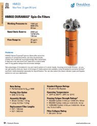
Proper Filter Application<br />
When selecting a new filter assembly or replacement<br />
filter, it’s important to first answer some basic<br />
questions about your application. Where will the<br />
filter be used? What is the required cleanliness level<br />
(ISO code) of your system? What type of oil are you<br />
filtering? Are there specific problems that needed to<br />
be addressed?<br />
It’s also important to think about the viscosity<br />
of the fluid in your system. In some machinery<br />
lubrication applications, for example, the oil is very<br />
thick and has a tougher time passing through the layer<br />
of media fibers. Heating techniques and the addition<br />
of polymers can make the liquid less viscous and<br />
therefore easier to filter. Another option is to install<br />
a filter with larger media surface area, such as the<br />
<strong>Donaldson</strong> W041 or HRK10 low pressure filters, that<br />
can accommodate more viscous fluids.<br />
Next, think about duty cycle and flow issues. Working<br />
components such as cylinders often create wide<br />
variations in flow—also called pulsating flow —that can<br />
be problematic for filters with higher efficiency ratings.<br />
On the other hand, dedicated off-line filtration (also<br />
called “kidney loop”) produces a very consistent flow,<br />
so it makes sense to use a more efficient filter. Learn<br />
more about off-line filtration on page 352.<br />
Filters used in applications with steady, continuous<br />
operation at lower pressures will last longer than filters<br />
that must endure cycles of high pressure pulsating<br />
flow. Generally, the lower the micron rating of a filter,<br />
the more often it needs to be changed since it is<br />
trapping more particles.<br />
Finally, it’s wise to ask yourself, “How much is my<br />
equipment worth?” Calculate how much it would cost<br />
to replace the equipment in your system, in case of<br />
component failure, and make sure those areas are well<br />
protected with proper filtration. (For example, high<br />
performance servo valves are very sensitive, costly<br />
components that need to be protected with finer<br />
filtration media.)<br />
Minimizing maintenance costs through good<br />
contamination control practices requires proper filter<br />
application based on the specific contamination<br />
problems. Good contamination control means costeffective<br />
filtration. When looking for a filter, first assess<br />
the needs of your system and any problem areas.<br />
Learn more about proper filter positioning on page 352.<br />
www.buydonaldson.com<br />
Fluid Properties<br />
<strong>Technical</strong> <strong>Reference</strong><br />
Characteristics to Consider<br />
When Specifying a <strong>Filtration</strong> System<br />
1) Oil Viscosity<br />
2) Flow<br />
3) Pressure<br />
4) What Components will be protected by the filter<br />
5) Cleanliness level required (expressed in<br />
ISO code)<br />
6) Type of oil/fluid<br />
7) Environment (the system, the surrounding<br />
conditions, etc.)<br />
8) Duty cycle<br />
9) Operating Temperature<br />
A <strong>Hydraulic</strong> System Design Worksheet is available on page 335.<br />
Lubricity The property of the fluid that keeps friction<br />
low and maintains an adequate film between moving<br />
parts.<br />
Viscosity The thickness of the fluid as measured by<br />
resistance to flow. The fluid must be thin enough to<br />
flow freely, heavy enough to prevent wear and leakage.<br />
<strong>Hydraulic</strong> fluids thicken when they cool and thin out as<br />
they heat up. Because some hydraulic systems work<br />
under wide temperature extremes, viscosity can be an<br />
important factor.<br />
Viscosity Index (VI) The rate of viscosity change<br />
with temperature: the higher the index, the more stable<br />
the viscosity as temperature varies. VI can sometimes<br />
be improved by additives, usually polymers.<br />
Rust Resistance Rust inhibiting chemicals in<br />
hydraulic fluids help overcome the effects of moisture<br />
from condensation.<br />
Oxidation Resistance Oxidation inhibitors delay the<br />
sludgy/acidic effects of air, heat, and contamination in<br />
the system.<br />
Foaming Resistance Although control of foaming<br />
depends largely on reservoir design, anti-foaming<br />
additives in the fluid also help.<br />
<strong>Hydraulic</strong> <strong>Filtration</strong> • 333<br />
HYDRAULIC FILTRATION - TECHNICAL REFERENCE
HYDRAULIC FILTRATION TECHNICAL REFERENCE<br />
<strong>Technical</strong> <strong>Reference</strong><br />
Types of <strong>Hydraulic</strong> Fluid<br />
There are many kinds of fluids used for power,<br />
but they can basically be called petroleum-based<br />
fluids, biodegradable fluids, and fire-resistant<br />
fluids. A brief description of some of the types<br />
in each category are listed below; for details on<br />
these or others, consult your filter supplier or<br />
refer to a reputable manual on hydraulics, such as<br />
the Lightning <strong>Reference</strong> Handbook, published by<br />
Berendsen Fluid Power, Whittier, CA 90601.<br />
Petroleum Based (Hydrocarbon)<br />
These are the most commonly used fluids in hydraulic<br />
systems. Their major advantages are low cost, good<br />
lubricity, relatively low/non-toxicity, and common<br />
availability. This type of fluid is not just plain oil; rather,<br />
it is a special formulation with additives that make it<br />
suitable for hydraulic systems. Mostly, the additives<br />
inhibit or prevent rust, oxidation, foam and wear.<br />
Variations:<br />
• Straight oils: same as petroleum-based oil but without<br />
the additives.<br />
• Automatic transmission fluids (ATF): excellent low temp<br />
viscosity and very high VI.<br />
• Military hydraulic fluids (ie: MIL-H-5606 and<br />
MIL-H-83282): also called ‘red oil’ because of the color.<br />
Low viscosity, good for cold temp operations, but may<br />
have to be modified for pumps.<br />
Fire Resistant Fluids<br />
There are two types of fire-resistant fluids<br />
commonly used in hydraulic applications: Phosphate<br />
Esters and High Water Based Fluids (HWBF). Although<br />
generally not as viscous at cold temperatures as<br />
petroleum-based fluids, they are fire resistant due to<br />
their high content of noncombustible material. Very<br />
useful in overcoming the likelihood of fire caused by a<br />
broken hydraulic line spraying petroleum fluid into a pit<br />
of molten metal, onto a hot manifold, into a heattreating<br />
furnace, or other ignition source.<br />
Some types of HWBF:<br />
• Oil-in-water emulsions (HFA): typically 95% water and<br />
5% oil, with the oil droplets dispersed throughout the<br />
water. Provide some fire resistance, but due to oil<br />
content, other fluids are superior.<br />
• Water-in-oil emulsions (invert emulsion HFB): typically<br />
40% water and 60% oil, with the water dispersed in the<br />
oil. Provide some fire resistance, but due to oil content,<br />
other fluids are superior.<br />
• Water-glycol (HFC): typically 40% water and 60% glycol.<br />
Excellent fire resistance. Since glycol is an antifreeze,<br />
water-glycol can be used at lower temps.<br />
NOTE: HWBF may require reduced pressure rating of pumps and<br />
other components.<br />
334 • <strong>Hydraulic</strong> <strong>Filtration</strong><br />
HFD Fluids<br />
The HFD group is a classification giben to several<br />
different types of synthetic products that do not contain<br />
petroleum oil or water. Phosphate ester fluids were<br />
the first HFD fluids and are the most fire resistant<br />
within the HFD family. Not as popular today, their use<br />
declined due to poor environmental performance,<br />
limited compatibility, and high cost. Certain phosphate<br />
esters have very high auto-ignition temperatures and<br />
are still used in specific applications, such as aircraft<br />
and power generation. A common brand is known<br />
as Sydrol® (registered trademark of Solution, <strong>Inc</strong>.).<br />
Skydrol requires EPR seal for chemical compatibility.<br />
Today most phosphate esters have been replaced by<br />
polyol esters. Based on organic esters, polyol esters<br />
are the most common HFD fluids used today. They offer<br />
good inherent fire resistance, good compatibility with<br />
system materials, excellent hydraulic fluid performance,<br />
and easy conversion from petroleum oil. In addition,<br />
the organic nature of these fluids gives them good<br />
environmental performance in biodegradability and<br />
aquatic toxicity. Another type of synthetic, fire resistant<br />
fluids have been formulated for certain niche markets.<br />
Water free polyalkylene glycols (PAGs) feature extended<br />
fluid life and good environmental performance.<br />
<strong>Technical</strong>ly an HFD fluid, PAGs (also known as<br />
polyalphaolefins (PAOs) are more often used for their<br />
biodegradability and overall environmental friendliness.<br />
This group also contains the synthetic silicone (siloxane)<br />
oils, known for their anti-foaming properties.<br />
Biodegradable<br />
With increasing concern about the environmental<br />
impact of hydraulic system leaks and spills,<br />
biodegradable fluids are receiving expanded<br />
usage, particularly in Europe. There are two<br />
types of common biodegradable hydraulic fluids:<br />
1) vegetable-based oils, such as sunflower or<br />
rapeseed oils, and 2) synthetic oils like diesters, etc.<br />
Generally, systems using biodegradable fluids are<br />
derated for maximum and minimum temperatures.<br />
Users who replace standard hydraulic oils with<br />
biodegradable oils must check with filtration component<br />
manufacturers to confirm that the fluid and components<br />
are compatible.<br />
www.buydonaldson.com
How Filter Media Functions<br />
In a <strong>Filtration</strong> System<br />
The job of the media is to capture particles and allow<br />
the fluid to flow through. For fluid to pass through, the<br />
media must have holes or channels to direct the fluid<br />
flow and allow it to pass. That’s why filter media is a<br />
porous mat of fibers that alters the fluid flow stream<br />
by causing fluid to twist, turn and accelerate during<br />
passage.<br />
The fluid changes direction as it comes into contact<br />
with the media fibers, as illustrated above. As the<br />
fluid flows through the media, it changes direction<br />
continuously as it works its way through the maze of<br />
media fibers. As it works its way through the depths<br />
of the layers of fibers, the fluid becomes cleaner and<br />
cleaner. Generally, the thicker the media, the greater<br />
the dirt-holding capacity it has.<br />
Looking at a cross-<br />
section view of the fibers,<br />
we can see how the<br />
flowstream is accelerated<br />
as it flows into the spaces<br />
between the fibers.<br />
www.buydonaldson.com<br />
<strong>Technical</strong> <strong>Reference</strong><br />
How Filter Media Collects Particles<br />
There are four basic ways media<br />
captures particles.<br />
The first, called inertia, works on large, heavy<br />
particles suspended in the flow stream. These<br />
particles are heavier than the fluid surrounding them. As<br />
the fluid changes direction to enter the fiber space, the<br />
particle continues in a straight line and collides with the<br />
media fibers where it is trapped and held.<br />
The second way media can capture particles is<br />
by diffusion. Diffusion works on the smallest<br />
particles. Small particles are not held in place<br />
by the viscous fluid and diffuse within the flow stream.<br />
As the particles traverse the flow stream, they collide<br />
with the fiber and are collected.<br />
The third method of particle entrapment is call<br />
interception. Direct interception works on particles<br />
in the mid-range size that are not quite large enough to<br />
have inertia and not small enough to diffuse within the<br />
flow stream. These mid-sized particles follow the flow<br />
stream as it bends through the fiber spaces. Particles<br />
are intercepted or captured when they touch a fiber.<br />
The fourth method of capture is called sieving<br />
and is the most common mechanism in hydraulic<br />
filtration. As shown at right, this is when the particle<br />
is too large to fit<br />
between the fiber<br />
spaces.<br />
<strong>Hydraulic</strong> <strong>Filtration</strong> • 335<br />
HYDRAULIC FILTRATION - TECHNICAL REFERENCE
HYDRAULIC FILTRATION TECHNICAL REFERENCE<br />
<strong>Technical</strong> <strong>Reference</strong><br />
Basic Types of <strong>Hydraulic</strong> Filter Media<br />
Filter Media<br />
Media is a term used to describe any material used to filter particles out of a fluid flow stream.<br />
There are six basic types used to remove contamination in hydraulic applications:<br />
Cellulose Media (Traditional)<br />
Cellulose fibers are actually wood fibers, microscopic in size and held together<br />
by resin. Fibers are irregular in both shape and size. Cellulose often has lower<br />
beta ratings, which means there are smaller pores in the media. Smaller media<br />
pores cause more flow resistance, resulting higher pressure drop.<br />
While cellulose provides effective filtration for a wide variety of petroleumbase<br />
fluids, in certain applications it results in poor filtration performance as<br />
compared to synthetic media.<br />
SEM 100x SEM 600x<br />
MEdia iMagE<br />
Synteq Media (Full Synthetic)<br />
Synthetic fibers are man-made, smooth, rounded and provide the least<br />
resistance to flow. Their consistent shape allows for control of the fiber size<br />
and distribution pattern throughout the media mat to create the smoothest,<br />
least inhibited fluid flow. Consistency of fiber shape allows the maximum<br />
amount of contaminant-catching surface area and specific pore size control.<br />
The result is media with predictable filtration efficiencies removing specified<br />
contaminants and maximum dirt holding capacity.<br />
The low resistance of synthetic media to fluid flow makes it ideal for use with<br />
synthetic fluids, water glycols, water/oil emulsions, HWCF and petroleumbased<br />
fluids.<br />
SEM 100x SEM 600x<br />
MEdia iMagE<br />
336 • <strong>Hydraulic</strong> <strong>Filtration</strong><br />
HOW iT WORkS<br />
HOW iT WORkS<br />
www.buydonaldson.com
DT Synteq Media (High-Performance)<br />
<strong>Donaldson</strong> high-performance DT grades of Synteq media utilize a blend<br />
of borosilicate glass fiber whose matrix is bonded together with an<br />
epoxy-based resin system. <strong>Donaldson</strong> filter media scientists found this to<br />
provides the best available chemical resistance for the broadest array of<br />
hydraulic applications.<br />
DT Synteq is ideal for use with phosphate ester and water glycol fluids.<br />
SEM 100x SEM 600x<br />
MEDiA iMAgE<br />
The chemical and thermal compatibility of fluid filters<br />
is an increasingly difficult design challenge due to the<br />
complex variety of fluid systems. Today’s fluid systems<br />
are often tailored towards the special needs fire<br />
resistance, biodegradability, and electrical insulating<br />
ability. Fortunately, there are chemical solutions<br />
available to meet these challenges.<br />
Average Beta Ratio<br />
10000<br />
1000<br />
100<br />
10<br />
www.buydonaldson.com<br />
<strong>Donaldson</strong> DT Synteq Media<br />
Beta 200<br />
Beta 1000<br />
<strong>Technical</strong> <strong>Reference</strong><br />
HOW iT WORkS<br />
<strong>Donaldson</strong> DT grades of Synteq media utilize a blend of<br />
borosilicate glass fiber whose matrix is bonded together<br />
with an epoxy-based resin system. <strong>Donaldson</strong> filter<br />
media scientists found this to provide the best available<br />
chemical resistance for the broadest array of hydraulic,<br />
fuel, and lube oil filtration applications.<br />
2 5 8<br />
14<br />
25<br />
DT 2UM<br />
DT 5UM<br />
DT 8UM<br />
DT 14UM<br />
DT 25UM<br />
0 5 10 15 20 25<br />
Particle Diameter (µm)<br />
<strong>Hydraulic</strong> <strong>Filtration</strong> • 337<br />
HYDRAULIC FILTRATION - TECHNICAL REFERENCE
HYDRAULIC FILTRATION TECHNICAL REFERENCE<br />
<strong>Technical</strong> <strong>Reference</strong><br />
Wire-Mesh Media<br />
Wire-mesh media consists of stainless steel, epoxy-coated wire mesh<br />
available in 3 mesh sizes:<br />
• 100 mesh yields 150 µm filtration<br />
• 200 mesh yields 74 µm filtration<br />
• 325 mesh yields 44 µm filtration<br />
Typically wire-mesh filters will be applied to catch very large, harsh<br />
particulate that would rip up a normal filter. You may also find this media<br />
useful as a coarse filter in viscous fluid applications.<br />
SEM 60x SEM 100x<br />
MEDiA iMAgE<br />
Water Absorbing Media<br />
Water absorption media quickly and effectively removes free water from<br />
hydraulic systems. Using super-absorbent polymer technology with a high<br />
affinity for water absorption, this media alleviates many of the problems<br />
associated with water contamination found in petroleum-based fluids.<br />
SEM 100x SEM 600x<br />
MEDiA iMAgE<br />
338 • <strong>Hydraulic</strong> <strong>Filtration</strong><br />
HOW iT WORkS<br />
HOW iT WORkS<br />
www.buydonaldson.com
www.buydonaldson.com<br />
<strong>Technical</strong> <strong>Reference</strong><br />
<strong>Donaldson</strong> Filter Media Efficiency Ratings per ISO 16889 Test Standards<br />
ISO 16889 is the international standard for<br />
Multi-Pass Testing to determine the efficiency (beta<br />
rating or beta ratio) and the dirt-holding capacity of<br />
the filter. It replaced the ISO 4572 test standard.<br />
<strong>Donaldson</strong> filter media has been re-tested per the<br />
new standard and the current beta ratios are shown<br />
at right. New beta ratios are shown at 200 and 1000,<br />
with a (c) to indicate test adherence to the ISO 16889<br />
standard and traceability to NIST test dust.<br />
Fluid to be Recommended<br />
Filtered Media<br />
Petroleum-based ................................Synteq or Cellulose<br />
Phosphate Ester ..............................................DT Synteq<br />
Diester ...................................................................Synteq<br />
Water Glycol ....................................................DT Synteq<br />
Water-Oil Emulsion ................................................Synteq<br />
Biodegradable Fluid ...............................................Synteq<br />
HWCF (high water content fluids) ........................Synteq<br />
Coarse <strong>Filtration</strong> ..............................................Wire Mesh<br />
<strong>Donaldson</strong> Filter Media Efficiency Ratings<br />
Per ISO 16889 Test Standards<br />
FORMER<br />
Media Rating NEW Rating NEW Rating<br />
Number Beta X=75 Beta X(C)=200 Beta X(C)=1000<br />
per ISO 4572 per ISO 16889 per ISO 16889<br />
<strong>Donaldson</strong> Synteq Synthetic Media<br />
No. ½ 2 µm 50 µm (c)<br />
<strong>Donaldson</strong> DT Synteq Synthetic Media<br />
DT 2µm<br />
DT 5µm<br />
DT 8µm<br />
DT 14µm<br />
N/A<br />
N/A<br />
N/A<br />
N/A<br />
40 µm (c)<br />
No. 25 N/A 32 µm (c) >40 µm (c)<br />
<strong>Donaldson</strong> Wire Mesh Media<br />
No. 44 45 µm nominal 325 mesh N/A<br />
No. 74 75 µm nominal 200 mesh N/A<br />
No. 149 150 µm nominal 100 mesh N/A<br />
<strong>Donaldson</strong> Water Absorbing Media<br />
WA N/A >30 µm(c) >30 µm(c)<br />
<strong>Hydraulic</strong> <strong>Filtration</strong> • 339<br />
HYDRAULIC FILTRATION - TECHNICAL REFERENCE
HYDRAULIC FILTRATION TECHNICAL REFERENCE<br />
<strong>Technical</strong> <strong>Reference</strong><br />
<strong>Hydraulic</strong> <strong>Filtration</strong> Pressure Drop<br />
The difference between the inlet pressure and<br />
the outlet pressure is called pressure drop or<br />
differential pressure. It’s symbolized by ∆P. ∆P is an<br />
irrecoverable loss of total pressure caused by the<br />
filter, and is mostly due to frictional drag on the<br />
fibers in the media.<br />
Differential drop drop may increase as the<br />
particulate rating or efficiency of the filter (as<br />
expressed by its beta ratio) gets better. ∆P<br />
also increases as the filter is being loaded with<br />
contaminant.<br />
Four Major Factors Contribute to Pressure Drop<br />
1. Filter Media<br />
Natural Fiber Cellulose media,<br />
as seen under the scanning<br />
electron microscope.<br />
340 • <strong>Hydraulic</strong> <strong>Filtration</strong><br />
Media is, of course,<br />
the main factor<br />
influencing pressure<br />
drop; indeed, it<br />
causes pressure<br />
drop. That’s why<br />
having a low-friction,<br />
high-flowing media<br />
is so important. The<br />
natural cellulose or<br />
paper fibers (shown<br />
at left) typically used<br />
in filtration are large, rough, and as irregular as nature<br />
made them.<br />
<strong>Donaldson</strong> developed a synthetic media with smooth,<br />
rounded fibers, consistently shaped so that we can<br />
control the fiber size and distribution pattern throughout<br />
the media mat, and still allow the smoothest, least<br />
inhibited fluid flow. Our synthetic media is named<br />
Synteq.<br />
<strong>Donaldson</strong>’s synthetic Synteq filter media<br />
— photo from scanning electron microscope<br />
— magnified hundreds of times.<br />
Synteq fibers offer the least amount of resistance to<br />
fluid passing through the media. Consistency of fiber<br />
shape allows the maximum amount of contaminantcatching<br />
surface area and specific pore size control.<br />
The result is media with predictable filtration<br />
efficiencies at removing specified contaminants<br />
(i.g., 4 µm) and maximum dirt holding capacity.<br />
Natural cellulose fibers are larger than synthetic fibers<br />
and jagged in shape, so controlling size of the pores in<br />
the media mat is difficult and there<br />
is less open volume. In most applications this results in<br />
higher ∆P as compared to synthetic<br />
filters. Higher beta ratings mean there are smaller<br />
pores in the media; smaller media pores cause more<br />
flow resistance, in turn causing higher pressure drop.<br />
2. Dirt, Contaminant<br />
As dirt gets caught in the media, it eventually begins<br />
to build up and fill the pore openings. As the pore<br />
openings shrink, the differential pressure (pressure<br />
drop) increases. This is called restriction. This photo<br />
from our scanning electron microscope shows actual<br />
dirt particles building up in the media pores.<br />
Excessive dirt<br />
in the media<br />
can cause dirt<br />
migration or<br />
even filter failure.<br />
Dirt migration<br />
occurs when the<br />
restriction is so<br />
great that the<br />
differential<br />
pressure pushes dirt deeper into the media and,<br />
eventually, through the media and back into the<br />
system. Filter failure occurs when the restriction<br />
becomes so high that the filter cartridge collapses<br />
(outside-in flow) or bursts (inside-out flow) to relieve<br />
the upstream pressure.<br />
To avoid such catastrophe, use of a filter service<br />
indicator is recommended. It measures the pressure<br />
drop across the filter, then signals when the filter is<br />
‘full’ and needs to be changed.<br />
www.buydonaldson.com
3. Flow<br />
Higher flows create higher pressure drop. With<br />
fast moving fluid, there will be more friction<br />
causing higher pressure drop across the media.<br />
4. Fluid Viscosity<br />
Measured in centistokes (cSt) or Saybolt Seconds<br />
Universal (SSU or SUS), fluid viscosity is the resistance<br />
of a fluid to flow. As fluid viscosity increases, the cSt<br />
rating increases. Higher fluid viscosities also mean<br />
higher pressure drop because the thicker oil has a<br />
tougher time passing through the layer of media fibers.<br />
Cold start fluid is a good example of highly viscous<br />
fluid. See chart below.<br />
Viscosity/Temperature Chart<br />
A.S.T.M. Standard Viscosity-Temperature Chart for Liquid Petroleum Products (D 341-43) Saybolt Universal Viscosity<br />
www.buydonaldson.com<br />
TYPE A<br />
AUTOMATiC<br />
TRANSMiSSiON FLUiD<br />
DiESEL<br />
FUEL<br />
JP4 AVERAgE<br />
kEROSENE<br />
<strong>Technical</strong> <strong>Reference</strong><br />
Filter media, amount of contamination, the flow rate,<br />
and fluid viscosity are all factors in the importance of<br />
sizing the filter for the system requirements. Filters<br />
that are too small won’t be able to handle the system<br />
flow rate and will create excessive pressure drop from<br />
the start. The results could be filter operation in the<br />
bypass mode, filter failure, component malfunction, or<br />
catastrophic system failures. Filters that are too large for<br />
the system can be too costly. Oversized filters require<br />
more system oil and higher cost replacement<br />
filters. Optimal sizing is best.<br />
SAE 140 gEAR OiL<br />
SAE 20<br />
MiL-H-5606<br />
SAE 30<br />
SAE 40<br />
SAE 50<br />
10W-30<br />
SAE 10<br />
<strong>Hydraulic</strong> <strong>Filtration</strong> • 341<br />
HYDRAULIC FILTRATION - TECHNICAL REFERENCE
HYDRAULIC FILTRATION TECHNICAL REFERENCE<br />
<strong>Technical</strong> <strong>Reference</strong><br />
Filter Design and Construction<br />
There are two main differences in a filter. The first is<br />
the design of the filter itself, and the second is the<br />
type of media that is used in the filter.<br />
Filter<br />
Filters have some attributes that are immediately<br />
obvious to the casual observer, such as height, inside<br />
diameter, outside diameter, media concentration,<br />
type of liner, seal design, and the way the media and<br />
components are glued or potted together.<br />
Liners<br />
Liners must be structurally sturdy to withstand pressure<br />
variance, yet open enough to allow good flow.<br />
Seals<br />
The top seal design must be leak-free, with a gasket or<br />
sealing device that ensures a good seal throughout the<br />
life of the filter. Standard seals are made of Buna-N ®<br />
material, which is fine for most applications. However, if<br />
the filtered fluid is diester or phosphate ester fluid, you’ll<br />
need a seal made of a fluoroelastomer such as Viton ®.<br />
Buna-N ® and Viton ® are registered trademarks of E. I. DuPont de Nemours and <strong>Company</strong>.<br />
Media Potting<br />
Media potting is key since it holds the media in place in<br />
between the end caps (not visiable). Not only should the<br />
potting be fully around the ends of the media to prevent<br />
leaks, it should also be of a material that can withstand<br />
the application. For instance, epoxy potting should be<br />
used in filters that must perform in higher temperature<br />
environments, phosphate ester fluids and some high<br />
342 • <strong>Hydraulic</strong> <strong>Filtration</strong><br />
water based fluids.<br />
Inside the filter, the media can vary in thickness, pleat<br />
depth and pleat concentration.<br />
For example, <strong>Donaldson</strong> hydraulic filters are<br />
generally equipped with either white (“Synteq ” our<br />
synthetic material) or natural brown (paper or cellulose<br />
material) media. It is important to note that media<br />
colors vary according to each manufacturer—it<br />
should not be assumed that any white-colored<br />
media is made of synthetic material.<br />
Some of the most important characteristics of<br />
filter media (structure, fiber diameter, volume solidity,<br />
basis weight, thickness, layering) can only be detected<br />
under a microscope.<br />
Damaged Equipment<br />
Damage happens when key<br />
filtration points are ignored!<br />
The pistons in this pump<br />
are severely damaged from<br />
contamination in the oil.<br />
www.buydonaldson.com
Combining the ISO Rating and<br />
Filter Performance Ratings<br />
While filter manufacturers publish beta ratings<br />
for filter media to describe efficiency performance<br />
levels, a direct connection between the beta rating<br />
scale and the ISO rating scale cannot be made.<br />
The solution is monitoring filter media performance<br />
at removing particles in the 4 µm, 6 µm, and 14 µm<br />
ranges. Fluid analysis and field monitoring are the<br />
only ways to get these measurements. Combine data<br />
from several tests to form a range of performance.<br />
Remember, actual filter performance will vary<br />
between applications.<br />
Here’s how to determine which filter media will best<br />
protect your hydraulic components: plot any media<br />
performance range on the Application Guide to<br />
<strong>Donaldson</strong> Filter Media (page 345), then connect the<br />
dots to make a line. On the same graph, plot your<br />
component requirement. (<strong>Reference</strong> chart below<br />
for some popular components, or ask your supplier<br />
for the recommended ISO rating.) If the line of the<br />
media falls below the ISO line, or if the bottom line<br />
of the filtration range does not intersect the ISO line,<br />
the component will be protected.<br />
Typical ISO Cleanliness<br />
Here are some typical<br />
ISO cleanliness<br />
recommendations from<br />
component manufacturers.<br />
(These are guidelines; always<br />
check the ratings specified<br />
by the manufacturer of your<br />
specific components.)<br />
www.buydonaldson.com<br />
Pressure 3000 PSi<br />
210 Bar >210 Bar<br />
Pumps --- iSO RATiNgS ---<br />
Fixed Gear Pump 19/17/15 18/16/13<br />
Fixed Vane Pump 19/17/14 18/16/13<br />
Fixed Piston Pump 18/16/14 17/15/13<br />
Variable Vane Pump 18/16/14 17/15/13<br />
Varibale Piston Pump 17/15/13 16/14/12<br />
Valves<br />
Directional (solenoid) 20/18/15 19/17/14<br />
Pressure (modulating) 19/17/14 19/17/14<br />
Flow Controls (standard) 19/17/14 19/17/14<br />
Check Valves 20/18/15 20/18/15<br />
Cartridge Valves 20/18/15 19/17/14<br />
Load-sensing Directional Valves 18/16/14 17/15/13<br />
Proportional Pressure Controls 18/16/13 17/15/12*<br />
Proportional Cartridge Valves 18/16/13 17/15/12*<br />
Servo Valves 16/14/11* 15/13/10*<br />
Actuators<br />
Cylinders 20/18/15 20/18/15<br />
Vane Motors 19/17/14 18/16/13<br />
Axial Piston Motors 18/16/13 17/15/12<br />
Gear Motors 20/18/15 19/17/14<br />
Radial Piston Motors 19/17/15 18/16/13<br />
* Requires precise sampling practices to verify cleanliness levels.<br />
Source: Vickers<br />
<strong>Technical</strong> <strong>Reference</strong><br />
Micron Sizes of Familiar Particles<br />
Grain of table salt 100 µm<br />
Human hair 80 µm<br />
Lower limit of visibility 40 µm<br />
White blood cell 25 µm<br />
Talcum powder 10 µm<br />
Red blood cell 8 µm<br />
Bacteria 2 µm<br />
Silt
HYDRAULIC FILTRATION TECHNICAL REFERENCE<br />
<strong>Technical</strong> <strong>Reference</strong><br />
Media Application Guide and ISO Rating System<br />
The Application Guide for <strong>Donaldson</strong> Filter Media<br />
on page 345 provides a data format for rating<br />
fluid contamination level and plotting filter media<br />
performance.<br />
The vertical numbers on the left side of the<br />
chart represent particle counts in a logarithmic<br />
progression of ten: .01, .1, 1,10, 102, 103, 104, 105<br />
and 106. (This represents the number of particle in<br />
the oil sample at the given size.) The numbers across<br />
the bottom of the chart represent particle size in<br />
microns.<br />
<strong>Donaldson</strong> media efficiency performance levels are<br />
derived from the ISO 16889 test standard with<br />
NIST-certified on-line automatic particle counters<br />
and ISO medium test dust. The <strong>Donaldson</strong> media<br />
efficiency performance levels shown are based on<br />
test averages under steady flow conditions. Actual<br />
performance levels may vary by application,<br />
viscosity, flow variance and contamination<br />
differences. Contact <strong>Donaldson</strong> or your <strong>Donaldson</strong><br />
distributor for specific application calculations.<br />
The international rating system for fluid<br />
contamination levels is called the ISO contamination<br />
code and it is detailed in the ISO 4406 document.<br />
Most component manufacturers publish filtration<br />
level recommendations using the ISO code. The<br />
ISO code, located on the right side of the media<br />
application guide on page 345, is easy to use if you<br />
remember the 4 µm, 6 µm and 14 µm numbers<br />
along the bottom of the chart.<br />
ISO 4406 Contamination Code<br />
µm à<br />
4 6 14<br />
This correlates to the numbers in the boxes along the right side of the graph on the next page.<br />
Range of number of particles per milliliter:<br />
Code More Than Up to & <strong>Inc</strong>luding<br />
24 80,000 160,000<br />
23 40,000 80,000<br />
22 20,000 40,000<br />
21 10,000 20,000<br />
20 5,000 10,000<br />
19 2,500 5,000<br />
18 1,300 2,500<br />
17 640 1,300<br />
16 320 640<br />
15 160 320<br />
344 • <strong>Hydraulic</strong> <strong>Filtration</strong><br />
Manufacturer’s ISO contamination levels are based<br />
on controlling the particle counts of 4 µm, 6 µm and<br />
14 µm particles in hydraulic system oil. This level<br />
is identified by measuring the number of particles<br />
4µm and greater, 6 µm and greater, and 14 µm and<br />
greater in one milliliter of the system hydraulic oil<br />
sample.<br />
How to Use the ISO Rating<br />
Example: A cartridge valve manufacturer recommends an<br />
ISO cleanliness level of 18/16/13.<br />
1) On the Application Guide for <strong>Donaldson</strong> Filter Media on the<br />
next page, place a dot on the vertical 4 µm line, horizontally<br />
even with the 18 box of the ISO code.<br />
2) Place a dot on the vertical 6 µm line horizontally even with<br />
the16 box of the ISO code.<br />
3) Place a dot on the vertical 14 µm line horizontally even with<br />
the13 box of the ISO code.<br />
4) Connect the dots to get the ISO cleanliness level 18/16/13.<br />
As illustrated below, particle counts falling on and above the<br />
18/16/13 line are damaging to the component and exceed the<br />
18/16/13 specification set by the manufacturer.<br />
Select a <strong>Donaldson</strong> media that falls below 18/16/13 to achieve<br />
cleanliness level tolerable to the component.<br />
Code More Than Up to & <strong>Inc</strong>luding<br />
14 80 160<br />
13 40 80<br />
12 20 40<br />
11 10 20<br />
10 5 10<br />
9 2.5 5<br />
8 1.3 2.5<br />
7 .64 1.3<br />
6 .32 .64<br />
iSO 18/16/13<br />
www.buydonaldson.com
Number of Particles per Milliliter<br />
10 6<br />
10 5<br />
10 4<br />
10 3<br />
10 2<br />
10 1<br />
10 0<br />
www.buydonaldson.com<br />
10 -1<br />
10 -2<br />
Logarithmic<br />
Scale á<br />
This represents the<br />
number of particles<br />
at a given size in<br />
the oil sample<br />
Application Guide for <strong>Donaldson</strong> Filter Media<br />
DT25 µm<br />
DT14 µm<br />
DT8 µm<br />
#2 Media<br />
DT5 µm<br />
#1 Media<br />
DT2 µm<br />
#½ Media<br />
4µm<br />
Particle Size<br />
#20 Media<br />
#9 Media<br />
ISO 18/16/13<br />
6µm 14µm<br />
<strong>Technical</strong> <strong>Reference</strong><br />
#2½, 3, 4 Media<br />
26<br />
25<br />
24<br />
23<br />
22<br />
21<br />
20<br />
19<br />
18<br />
17<br />
16<br />
15<br />
14<br />
13<br />
12<br />
11<br />
10<br />
9<br />
8<br />
7<br />
6<br />
5<br />
4<br />
3<br />
2<br />
1<br />
Contamination Code Number<br />
<strong>Hydraulic</strong> <strong>Filtration</strong> • 345<br />
HYDRAULIC FILTRATION - TECHNICAL REFERENCE
HYDRAULIC FILTRATION TECHNICAL REFERENCE<br />
<strong>Technical</strong> <strong>Reference</strong><br />
Filter Efficiency Standards<br />
Understanding the Beta Rating System<br />
This information is provided as an aid to<br />
understanding fluid filter efficiency terminology<br />
based on current ISO, ANSI and NFPA test standards.<br />
It is not proprietary and may be reproduced or<br />
distributed in any manner for educational purposes.<br />
What is Beta Ratio?<br />
Beta ratio (symbolized by ß) is a formula used<br />
to calculate the filtration efficiency of a particular fluid<br />
filter using base data obtained from multi-pass testing.<br />
In a multi-pass test, fluid is continuously injected with<br />
a uniform amount of contaminant (i.e., ISO medium<br />
test dust), then pumped through the filter unit being<br />
tested. Filter efficiency is determined by monitoring<br />
oil contamination levels upstream and downstream of<br />
the test filter at specific times. An automatic particle<br />
counter is used to determine the contamination level.<br />
Through this process an upstream to downstream<br />
particle count ratio is developed, known as the beta<br />
ratio. The formula used to calculate the beta ratio is:<br />
Beta ratio (x) = particle count in upstream oil___<br />
particle count in downstream oil<br />
where (x) is a given particle size<br />
Indicates that testing was done with<br />
APC’s calibrated with NIST fluid<br />
ß10(c) = 1000<br />
346 • <strong>Hydraulic</strong> <strong>Filtration</strong><br />
1000 times more particles<br />
upstream than downstream<br />
that are 10 µm and larger<br />
Find further information on ISO 16889<br />
at www.NFPA.com or your ISO document source.<br />
Ask for ISO/TR16386: 1999 “The Impact of<br />
Changes in ISO Fluid Power Particle Counting—<br />
Contamination Control and Filter Test Standards.”<br />
Why the Efficiency Rating Test Standard<br />
was Updated<br />
The International Industry Standard (ISO) for multipass<br />
testing provides a common testing format for<br />
filter manufacturers to rate filter performance. This<br />
standardization gives you the ability to reliably compare<br />
published filter ratings among different brands of filters.<br />
ISO test standards were updated in 1999 to reflect the<br />
improved technology available in<br />
particle counters and other test equipment. The newer<br />
particle counters provide more precise counting and<br />
greater detail— reflecting a truer indication of filter<br />
performance.<br />
The National Fluid Power Association (NFPA), the<br />
National Institute of Standards & Technology (NIST),<br />
and industry volunteers, including several engineers<br />
from <strong>Donaldson</strong>, helped revise the ISO standard. ISO<br />
16889 has been in force since late 1999 and ISO 4572 is<br />
officially discontinued.<br />
Better Test Dust<br />
The old test dust (AC fine test dust or ACFTD) was “ball<br />
milled,” which produced dust particles of varying size<br />
and shape. Particle distribution was often different from<br />
batch to batch. The accuracy of ACFTD distribution and<br />
previous APC calibration procedure was questioned<br />
by industry, due to lack of traceability and certification.<br />
ACFTD hasn’t been produced since 1992.<br />
Now, the new test dust (ISO medium test dust)<br />
is “jet milled” to produce consistent particle size, shape,<br />
and distribution from batch to batch. See dust size<br />
comparison chart below.<br />
Liquid Automatic Particle Counters (APC’s)<br />
In the old test standard (ISO 4572), fluid samples<br />
obtained in bottles and off-line particle counting were<br />
allowed. Now, in the updated standard<br />
(ISO 16889), on-line, laser-based automatic<br />
particle counters, especially made for measuring<br />
liquids, are required and bottle counting methods are<br />
disallowed, as illustrated on next page.<br />
www.buydonaldson.com
The old particle counter calibration was based<br />
on only one dimension of an irregularly-shaped<br />
particle (the longest cord). Today, the particle counter<br />
calibration is based on equivalent spherical area of<br />
an irregularly-shaped particle.<br />
NIST provides calibration suspension, which is<br />
certified with X number of particles at a certain<br />
size. This is verified by NIST. The new way to list<br />
beta ratios includes a subscript (c) to indicate<br />
NIST certified test suspension and assures you of<br />
traceability and repeatability.<br />
Injection<br />
Reservoir<br />
pump<br />
www.buydonaldson.com<br />
Test<br />
Reservoir<br />
pump<br />
Down<br />
Stream<br />
Up Stream<br />
Test<br />
Filter<br />
* APC = Liquid Automatic<br />
Particle Counter<br />
<strong>Technical</strong> <strong>Reference</strong><br />
Overall, you can have strong confidence in filter<br />
ratings resulting from tests per ISO 16889, as they<br />
are highly accurate. As always, keep in mind that<br />
beta ratings are laboratory measurements under<br />
steady flow conditions with artificial contaminants<br />
— the real proof of the performance is how clean the<br />
filter keeps the fluids in the application. A good oil<br />
analysis program that checks the cleanliness of the<br />
oil periodically will verify that the proper filters are<br />
being used.<br />
Test Dust Size Comparisons<br />
ACFTD calibrated size (µm) per iSO 4402 corresponds to a NiST-calibrated size [µm (c)] per iSO 11171<br />
ACFTD 0.8 1 2 2.7 3 4.3 5 7 10 12 15 15.5 20 25 30 40 50<br />
NiST 4 4.2 4.6 5 5.1 6 6.4 7.7 9.8 11.3 13.6 14 17.5 21.2 24.9 31.7 38.2<br />
Injection<br />
Reservoir<br />
pump<br />
Test<br />
Reservoir<br />
flow meter<br />
pump<br />
flow meter<br />
Down<br />
Stream<br />
Up<br />
Stream<br />
Test<br />
Filter<br />
Online<br />
APC*<br />
Online<br />
APC*<br />
Bottle<br />
Sample<br />
Bottle<br />
Sample<br />
iSO 16889<br />
n In-Line Liquid Automatic Particle<br />
Counters (APC) are now<br />
required for proper testing.<br />
n APC calibration follows<br />
ISO 11171 procedures<br />
n ISO 11171 uses NIST (National<br />
Instistute of Standards & Technology)<br />
certified calibration fluid<br />
iSO 4572<br />
(Discontinued)<br />
n Either bottle samples<br />
or APC’s were allowed.<br />
n APC calibration followed ISO4402<br />
ACFTD (Discontinued)<br />
<strong>Hydraulic</strong> <strong>Filtration</strong> • 347<br />
HYDRAULIC FILTRATION - TECHNICAL REFERENCE
HYDRAULIC FILTRATION TECHNICAL REFERENCE<br />
<strong>Technical</strong> <strong>Reference</strong><br />
Highlights of ISO 16889<br />
• ISO 4572 is now replaced by ISO 16889<br />
as the international standard for Multi-Pass Tests to<br />
determine the efficiency (beta rating or beta ratio)<br />
and the dirt-holding capacity of the filter.<br />
• The test bench for ISO 16889 must have<br />
On-Line Liquid Automatic Optical Particle Counters<br />
(APC) calibrated using NIST (National Institute of<br />
Standards & Technology)-certified calibration fluid.<br />
This includes added enhancements to APC’s, to<br />
allow for better resolution, accuracy, repeatability and<br />
reproducibility.<br />
• ISO 12103-1,A3 (ISO Medium, 5µm-80µm<br />
• Test Dust was selected as replacement dust for<br />
calibration and testing procedures.<br />
• APC’s are calibrated by passing a sample of<br />
calibration fluid with a known particle size distribution<br />
and producing a calibration curve to match the<br />
known count distribution.<br />
• NIST used the Scanning Electron Microscope<br />
analysis and statistical analysis techniques to certify<br />
the particle size distribution.<br />
• Particle counts, upstream and downstream, are<br />
taken every minute of the test.<br />
• Beta ratios are reported with (c) to designate NIST<br />
traceability.<br />
iSO 16889 recommends reporting beta ratings at:<br />
Rating Efficiency<br />
2 .......................50%<br />
10 .....................90%<br />
75 .....................98.7%<br />
100 ...................99%<br />
200 ...................99.5%<br />
1000 .................99.9%<br />
Example: ß4(c) =200 signifies that there are 200<br />
times as many particles that are 4 µm and larger<br />
upstream as downstream. This is 99.5% efficiency.<br />
Example: ß5(c) =1000 indicates that there are 1000<br />
times as many particles that are 5 µm and larger<br />
upstream as downstream. This is 99.9% efficiency.<br />
348 • <strong>Hydraulic</strong> <strong>Filtration</strong><br />
<strong>Donaldson</strong> <strong>Hydraulic</strong> Filter Media<br />
Beta Ratings<br />
<strong>Donaldson</strong> hydraulic filter media beta ratings are<br />
average ratings obtained from multi-pass tests<br />
performed per the new ISO 16889 standard.<br />
According to the ISO standard, each filter<br />
manufacturer can test a given filter at a variety<br />
of flow rates and terminal pressure drop ratings<br />
that fit the application, system configuration<br />
and filter size. Your actual performance may<br />
vary depending on the configuration of the<br />
filter tested and test conditions.<br />
<strong>Donaldson</strong> Filter Media Efficiency Ratings<br />
Per ISO 16889 Test Standards<br />
FORMER<br />
Media Rating NEW Rating NEW Rating<br />
Number Beta X=75 Beta X(C)=200 Beta X(C)=1000<br />
per ISO 4572 per ISO 16889 per ISO 16889<br />
<strong>Donaldson</strong> Synteq Synthetic Media<br />
No. ½ 2 µm 50 µm (c)<br />
<strong>Donaldson</strong> DT Synteq Synthetic Media<br />
DT 2µm<br />
DT 5µm<br />
DT 8µm<br />
DT 14µm<br />
N/A<br />
N/A<br />
N/A<br />
N/A<br />
40 µm (c)<br />
No. 25 N/A 32 µm (c) >40 µm (c)<br />
<strong>Donaldson</strong> Wire Mesh Media<br />
No. 44 45 µm nominal 325 mesh<br />
No. 74 75 µm nominal 200 mesh<br />
No. 149 150 µm nominal 100 mesh<br />
<strong>Donaldson</strong> Water Absorbing Media<br />
WA N/A >30 µm(c) >30 µm(c)<br />
www.buydonaldson.com
Cleanliness Level Correlation Table<br />
Conversion of cleanliness specifications to filter<br />
performance is not an exact science because the<br />
contamination level in a hydraulic system is a<br />
function of the ingression and generation rate as<br />
well as the filter performance.<br />
Factors That Affect Cleanliness Levels<br />
in a <strong>Hydraulic</strong> System<br />
• Abrasive wear in space between adjacent moving<br />
surfaces of components.<br />
• Erosive wear at component edges or direction<br />
changes where there is high fluid velocity.<br />
• Fatigue wear by particles trapped between moving<br />
surfaces.<br />
Identification of the Most Sensitive<br />
Component<br />
• Required cleanliness level is dominated by the<br />
component with smallest clearances and/or highest<br />
loading on the lubricating film.<br />
• Best source for determining this level is the<br />
specification published by the component<br />
manufacturer.<br />
• Higher pressures reduce component life, unless<br />
contamination level is decreased accordingly.<br />
• Operating at half the rated pressure of component will<br />
increase its life by more than four times.<br />
• Percent of operating time at maximum<br />
pressure depends on individual machines<br />
and application.<br />
www.buydonaldson.com<br />
<strong>Technical</strong> <strong>Reference</strong><br />
iSO Particles iSO FTD* Mil Std NAS<br />
Code Per Milliliter gravimetric 1236A 1638 SAE Level<br />
>10 microns Level (mg/l) (1967) (1964) (1963)<br />
30/26/23 140,000 1000<br />
29/25/23 85,000 1000<br />
26/25/20 14,000 100 700<br />
23/21/18 4,500 12<br />
2220/18 2,400 500<br />
22/20/17 2,300 11<br />
21/20/17 1,400 10<br />
21/19/16 1,200 10<br />
20/18/15 580 9 6<br />
19/17/14 280 300 8 5<br />
18/16/13 140 1 7 4<br />
17/15/12 70 6 3<br />
16/14/12 40 200<br />
16/14/10 35 5 2<br />
15/13/10 14 0.1 4 1<br />
14/12/9 9 3 0<br />
13/11/8 5 2<br />
12/10/8 3 100<br />
12/10/7 2.3 1<br />
11/10/6 1.4 0.01<br />
11/9/6 1.2 0<br />
10/8/5 0.6 0<br />
9/7/5 0.3 50<br />
8/6/3 0.14 0.001<br />
7/5/2 0.04 25<br />
6/2/.8 0.01 10<br />
* SAE Fine Test Dust — ISO approved test and calibration contaminant.<br />
Source: Milwaukee School of Engineering Seminar, Contamination &<br />
<strong>Filtration</strong> of <strong>Hydraulic</strong> Systems<br />
<strong>Hydraulic</strong> <strong>Filtration</strong> • 349<br />
HYDRAULIC FILTRATION - TECHNICAL REFERENCE
HYDRAULIC FILTRATION TECHNICAL REFERENCE<br />
<strong>Technical</strong> <strong>Reference</strong><br />
Compatibility of <strong>Donaldson</strong> Filter<br />
Media with <strong>Hydraulic</strong> Fluids<br />
While <strong>Donaldson</strong> has developed many formulations<br />
of media, they can be divided into two broad<br />
categories: natural fibers, usually cellulose, and<br />
synthetic or man-made fibers.<br />
350 • <strong>Hydraulic</strong> <strong>Filtration</strong><br />
Recommended Filter Media<br />
Petroleum-Based (Hydrocarbon) Fluids Cellulose Synteq DT Synteq<br />
Straight oils Yes Yes Yes<br />
ATFs Yes Yes Yes<br />
Military hydraulic fluids Yes Yes Yes<br />
#2 Diesel fuel Yes Yes Yes<br />
Gasoline Yes Yes Yes<br />
E85 (85/15 Ethanol/Gasoline) No No Yes<br />
Fire Resistant Fluids Cellulose Synteq DT Synteq<br />
HFA - Oil-in-water emulsion No
A Note on Seals<br />
www.buydonaldson.com<br />
<strong>Technical</strong> <strong>Reference</strong><br />
• Filters with seals made of Buna-N ® are appropriate for most applications involving petroleum oil and some high<br />
water content fluids. Filters with seals made of Viton ® or Fluorel ® (both fluoroelastomers) are required when<br />
using diesters, phosphate ester fluids. <strong>Donaldson</strong> offers both types. EPR (ethylene propylene rubber) seals are<br />
required for use with Skydrol ® and Skydrol 500 fluids.<br />
Buna-N ® and Viton ® are registered trademarks of E. I. DuPont de Nemours and <strong>Company</strong>. Skydrol is a registered trademarks of Solutin, <strong>Inc</strong>.<br />
• In <strong>Donaldson</strong> filters with fluorocarbon elastomer seals, epoxy potting is used to accommodate higher<br />
temperature environments and for compatibility with fluids such as phosphate ester, diesters, and high water<br />
based fluids. The plastisol (heat cured) and urethane (self curing) potting materials used in other filters perform<br />
well with petroleum-based fluids.<br />
Seal Installation Instructions<br />
Remember...<br />
• Over-tightening filter may damage head.<br />
• Dispose of used filter properly<br />
O-Ring Seal<br />
P166435<br />
1. Remove used seal and clean<br />
gasket seat in head. Apply<br />
clean oil to new surfaces.<br />
2. Install new seal on inside lip<br />
of filter.<br />
3. Screw on new filter until<br />
gasket makes contact. Tighten<br />
filter until top edge makes<br />
metal to metal contact with<br />
filter head (approximately 1½<br />
turns).<br />
O-Ring O-Ring O-Ring<br />
L-Cut<br />
L-Cut<br />
L-Cut Gasket<br />
P170894 or P569908<br />
1. Remove used seal and clean<br />
gasket seat in head. Apply<br />
clean oil to new surfaces.<br />
2. Install new seal on inside lip<br />
of filter.<br />
3. Screw on new filter until<br />
gasket makes contact. Tighten<br />
filter an additional ¾ turn.<br />
Square-Cut Gasket<br />
P165641<br />
Square Square Cut<br />
Cut<br />
1. Remove old gasket and clean<br />
groove in head. Apply clean oil<br />
to new gasket surfaces.<br />
2. Install new gasket into groove<br />
in filter head.<br />
3. Screw on new filter until<br />
gasket makes contact. Tighten<br />
filter an additional ¼ turn.<br />
<strong>Hydraulic</strong> <strong>Filtration</strong> • 351<br />
HYDRAULIC FILTRATION - TECHNICAL REFERENCE
HYDRAULIC FILTRATION TECHNICAL REFERENCE<br />
<strong>Technical</strong> <strong>Reference</strong><br />
How to Best Position Filters in Your <strong>Hydraulic</strong> Circuit<br />
Within every hydraulic circuit<br />
there are many possible places<br />
for filters.<br />
The best systems are strategically<br />
engineered to ensure that oil is<br />
filtered properly at each stage of<br />
its journey through the circuit.<br />
Ideally, filtration should occur in<br />
the following places:<br />
• In the Reservoir<br />
• Before/After the Pump<br />
• In the Return-line System<br />
• Off-line<br />
In reality, many companies have<br />
to make tough decisions about<br />
which filters they can afford and<br />
which ones they’ll have to live<br />
without.<br />
Much depends on the cleanliness<br />
level requirements of the<br />
components, environment, duty<br />
cycle of the equipment and other<br />
variables that can vary from<br />
application to application.<br />
This diagram shows<br />
how various types of<br />
filters can be used in<br />
hydraulic circuits.<br />
352 • <strong>Hydraulic</strong> <strong>Filtration</strong><br />
PM<br />
Suction<br />
Filter<br />
Pump<br />
Kidney Loop Filters<br />
Kidney<br />
Loop<br />
Filter<br />
Breather<br />
Portable Kidney<br />
Loop Filter Cart<br />
Benefit: High<br />
Sometimes referred to as “off-line”<br />
filters, kidney loop filters achieve<br />
very fine filtration by maintaining<br />
steady-state flow, independent of<br />
the hydraulic circuit.<br />
With this type of filtration, the entire<br />
hydraulic system can keep operating<br />
while the kidney loop filter is being<br />
serviced.<br />
A kidney loop filter utilizes lowpressure<br />
housings that are easily<br />
accessible and serviceable. These<br />
filters can either be integrated into<br />
the main hydraulic reservoir, or<br />
used in mobile filter carts like the<br />
one shown at left to service many<br />
hydraulic systems.<br />
Relief<br />
Valve<br />
Pressure<br />
Filter<br />
Suction<br />
Strainer<br />
Note that kidney loop filters do<br />
not directly protect components —<br />
rather, their main function is<br />
to polish the oil to a very clean<br />
condition. It’s also important<br />
to remember that an additional<br />
pump and motor will be required.<br />
Filler / Breather<br />
Benefit: High<br />
Tank breathers are placed on<br />
hydraulic reservoirs to prevent<br />
atmospheric contamination from<br />
entering and<br />
to allow for<br />
sufficient air<br />
movement inside<br />
the reservoir.<br />
Breathers should<br />
prevent particles<br />
larger than 3 microns<br />
from entering the system. This is<br />
a sensible, affordable solution for<br />
any hydraulic system, but by all<br />
means cannot be the only filter on a<br />
hydraulic system.<br />
PM<br />
Return-Line<br />
Filter<br />
www.buydonaldson.com
Suction Filter<br />
Benefit: Medium<br />
Normally placed between the<br />
reservoir and the pump, suction<br />
filters are designed to remove<br />
particles in the 5 to 150 micron<br />
range. They are easier to service<br />
and less expensive than many<br />
other types of filters—but because<br />
restriction in the suction line must<br />
be kept very low, filter housing size<br />
tends to be larger than similar flow<br />
return or pressure filter housings.<br />
The most popular application for<br />
suction filters is with variable-speed<br />
hydrostatic pumps commonly found<br />
in off-road mobile applications and<br />
industrial variable-speed drives.<br />
They are also often used in harsh<br />
environments and charge pump<br />
applications.<br />
Suction Strainer<br />
Benefit: Low<br />
Suction strainers, or sump-type<br />
filters, are often used in hydraulic<br />
fluid reservoirs. Their only real use is<br />
to keep cigarette butts, moths, nuts<br />
& bolts and the like out of the pump.<br />
Instead, such contaminants can<br />
easily be eliminated by keeping the<br />
reservoir sealed and by using<br />
a Filler/Breather and Return-<br />
Line Filter.<br />
www.buydonaldson.com<br />
Return-Line Filter<br />
Benefit: High<br />
The advantages of return-line filters<br />
are many. They are usually lowpressure<br />
housings, which are less<br />
typically expensive. Their purpose<br />
is to collect the dirt from around<br />
the circuit as the oil returns to the<br />
reservoir. Much like the kidney<br />
loop, the return-line filter provides<br />
ultimate flexibility in positioning—<br />
it can perform almost anywhere<br />
within the return line circuit, either<br />
mounted inline or built into the<br />
reservoir.<br />
Downsides are few, but worth<br />
noting: return-line filters can<br />
be subject to flow surges<br />
(which contribute to poor filter<br />
performance) and they do not<br />
filter the drain lines.<br />
Note regarding return-line and kidneyloop<br />
filtration: If you’re looking for<br />
a great value filter that’s easy to<br />
maintain and with lots of media<br />
choices, this is a wise investment.<br />
Although these filters are very<br />
common, one downside is that<br />
there are very few standards of<br />
consistency from one manufacturer<br />
to the next, so replacement<br />
cartridges are not necessarily<br />
interchangeable.<br />
<strong>Technical</strong> <strong>Reference</strong><br />
Pressure Filter<br />
Benefit: High<br />
This is also known as “last-chance”<br />
filtration. High pressure filters<br />
keep clean the oil that comes<br />
directly from the pump<br />
so that the more<br />
expensive downstream<br />
components (such<br />
as valves and<br />
actuators) are<br />
protected.<br />
Pressure line filters<br />
offer protection<br />
from catastrophic<br />
pump failure. They<br />
are a worthwhile<br />
investment for highvalue<br />
systems — as are found in<br />
the aircraft industry, paper and steel<br />
mills, plastic injection molding, and<br />
in die-casting machines.<br />
One downside to high pressure<br />
filters is, ironically, the high<br />
pressure. The entire system must<br />
be stopped in order to service<br />
a high-pressure filter—unless a<br />
duplex configuration is used.<br />
When oil is shooting out of a<br />
pump at 6000+ psi, it will take<br />
out anything in its way! By nature,<br />
a high-pressure pump is a prime<br />
mover of fluids, so it will experience<br />
significant wear over time. Service<br />
can also be more difficult because<br />
of its heavy-duty construction—as<br />
anyone who’s ever tried to change<br />
a slippery, 200-pound cast-iron filter<br />
can attest.<br />
<strong>Hydraulic</strong> <strong>Filtration</strong> • 353<br />
HYDRAULIC FILTRATION - TECHNICAL REFERENCE
<strong>Donaldson</strong> Delivers<br />
Performance<br />
Under Any<br />
Pressure.<br />
In-Tank<br />
<strong>Hydraulic</strong> Filter<br />
Pressure Gauges<br />
Medium Pressure<br />
<strong>Hydraulic</strong> Filter<br />
Breather<br />
Low Pressure<br />
<strong>Hydraulic</strong> Filters<br />
www.donaldsonfilters.com<br />
High Pressure<br />
<strong>Hydraulic</strong> Filter<br />
Level Gauge<br />
PRODUCT INFORMATION<br />
HYDRAULIC<br />
www.donaldsonfilters.com<br />
354 • <strong>Hydraulic</strong> <strong>Filtration</strong> www.buydonaldson.com
www.buydonaldson.com<br />
hydraulic filtration for vehicles/equipment<br />
application design worksheet<br />
For proper development/design engineering solution, we<br />
ask you to provide details about your engine, project due<br />
dates, hydraulic or transmission system and performance<br />
(mechanical and filtration), system mounting, service,<br />
final packaging and product markings.<br />
Customer Name: Revision:<br />
Project Name:<br />
Contact Name: Title<br />
Phone: Fax: Email:<br />
Current <strong>Donaldson</strong> Model Used: (if applicable) Your Part Number:<br />
Target Cost:<br />
project details<br />
Type of Vehicle/Machine: _______________________<br />
Units Per Year: ____________<br />
Key Project Dates:<br />
Design Proposal: ____________________<br />
Quote ____________________<br />
Sample Delivery: ____________________<br />
Design Freeze: ____________________<br />
PPAP: ____________________<br />
Start of Production: ____________________<br />
application information<br />
Components That Need Protection<br />
¨ Pump (type?): _____________________________<br />
¨ Circuit: ¨ <strong>Hydraulic</strong> ¨ Pilot<br />
¨ Transmission: ¨ Hydrostatic ¨ Powershift<br />
Filter Location:<br />
¨ Suction ¨ Pressure ¨ Return<br />
¨ Side Loop ¨ Charge ¨ Sump<br />
¨ Other .. __________________________________<br />
Port Size & Type:<br />
NPT: ¨1/2” ¨3/4” ¨1-1/4” ¨1-1/2” ¨2-1/2”<br />
SAE O-ring: ¨-8 ¨-12 ¨-16 ¨-20 ¨-24<br />
4 Bolt Flange: ¨ 2” SAE ¨ 3” SAE ¨4” ANSI<br />
¨2” Code 61 ¨2-1/2” Code 61<br />
Other ....... __________________________________<br />
When completed, please forward to <strong>Donaldson</strong>.<br />
Email: engine@donaldson.com<br />
Fax: 952-887-3502<br />
Mounting Requirements:<br />
______________________________ _____________<br />
operating conditions<br />
Flow Rates: ¨ lpm or ¨ gpm<br />
Min ________ Normal ________ Max ________<br />
Oil System Pressure (psi/kPa):<br />
Minimum ______ Normal ______ Maximum ______<br />
Temperature: ¨ º C or ¨ º F<br />
Fluid: Min ______ Normal ________ Max ________<br />
Ambient: Min ______ Normal _______ Max ______<br />
Fluid Type:<br />
¨ Petroleum ¨ Water-glycol<br />
¨ Phosphate-ester ¨ HWBF<br />
¨ Other ________________________________<br />
Viscosity: (2 required)<br />
_________ cSt or Ssu @ _____________º C Temp<br />
_________ cSt or Ssu @ _____________º C Temp<br />
filtration performance<br />
ISO Contamination Level Required _______________<br />
Beta 200/1000 = ______ / _______<br />
Filter Media: .........¨ Synthetic ¨ Cellulose<br />
¨ Wire<br />
More on next page.<br />
<strong>Hydraulic</strong> <strong>Filtration</strong> • 355<br />
HYDRAULIC FILTRATION - TECHNICAL REFERENCE
HYDRAULIC FILTRATION TECHNICAL REFERENCE<br />
Capacity:<br />
________ gms ISO Medium @ ______ flow to ________ psid<br />
Pressure Drop Limits:<br />
Limits psid Flow Viscosity<br />
1 @ @<br />
2 @ @<br />
3 @ @<br />
Structural performance<br />
Hydrostatic Pressure Resistance (Burst):<br />
Test Method : _______________________________<br />
Minimum Value: __________________psid / kPa<br />
Collapse Pressure:<br />
Test Method : _______________________________<br />
Minimum Value: __________________psid / kPa<br />
Pressure Testing:<br />
Min. Cycles Range (psid)<br />
Hydrodynamic to<br />
Flow Fatigue to<br />
Vibration to<br />
Frequency<br />
(Hz)<br />
Cracking Pressure:<br />
Test Method : _______________________________<br />
Minimum Value: __________________ psid / kPa<br />
By-pass Valve: ¨ In Head ¨ In Filter<br />
Setting: __________ psid / kPa<br />
Leak Testing:<br />
Test Method : _______________________________<br />
Minimum Value: __________________ psid / kPa<br />
for donaldson use only<br />
additional information<br />
filter service<br />
Indicator Type: ¨ Electric<br />
Type: ______________________<br />
Filter Change Interval:<br />
_________________ ¨ km or ¨ miles or ¨ hours<br />
_<br />
Do you require installation, service or maintenance<br />
recommendations from <strong>Donaldson</strong>? ¨ Yes ¨ No<br />
___________________________<br />
packaging<br />
Do you have any special packaging requirements?<br />
¨ Yes ¨ No If yes, please check all that apply:<br />
Protective caps: ¨ on inlet ¨ on outlet ¨ on port<br />
Final Assembly:<br />
¨ Bulk / Bagged ¨ Bulk/Individual Boxes<br />
¨ Other _________________________________<br />
_________________________________<br />
product markings/identity<br />
Do you have any product marking requirements?<br />
Head Assembly? ¨ Yes ¨ No<br />
Filters? ¨ Yes ¨ No<br />
If yes, artwork it is assumed customer will provide<br />
artwork for filter markings. <strong>Donaldson</strong> can provide<br />
marking area for artwork design. Standard installation<br />
icons are available from <strong>Donaldson</strong>.<br />
special requirements or application notes<br />
Use this area to provide additional information that will<br />
assist <strong>Donaldson</strong> engineering.<br />
Date Received: _____________________________ Request From: ¨ Catalog ¨ Web Site<br />
¨ Other _______________________<br />
Assigned to:<br />
Business Unit: _____________________________ Account Manager: _________________________<br />
Product Manager: __________________________ Engineer: _________________________________<br />
donaldson company, inc.<br />
PO Box 1299<br />
Minneapolis, MN 55440-1200<br />
<strong>Hydraulic</strong> Applications Engineering<br />
doc. no. f115354 rev.1 January 2012<br />
© 2012 <strong>Donaldson</strong> <strong>Company</strong>, <strong>Inc</strong>. All rights reserved. Printed in the U.S.A.<br />
<strong>Donaldson</strong> <strong>Company</strong>, <strong>Inc</strong>. reserves the right to change or discontinue any model<br />
or specification at any time and without notice.<br />
donaldson company, inc., po Box 1299, minneapolis, mn 55440-1299<br />
356 • <strong>Hydraulic</strong> <strong>Filtration</strong> www.buydonaldson.com