

Mallory 560 Ignition Conversion Kit Installation Instructions - Jegs
Mallory 560 Ignition Conversion Kit Installation Instructions - Jegs
Mallory 560 Ignition Conversion Kit Installation Instructions - Jegs

Create successful ePaper yourself
Turn your PDF publications into a flip-book with our unique Google optimized e-Paper software.
INSTALLATION INSTRUCTIONS<br />
FORM 1466 (REV. D) 10/03<br />
UNILITE ® ELECTRONIC BREAKERLESS CONVERSION KIT<br />
FOR MALLORY POINT DISTRIBUTORS<br />
NOTE: This product is legal in California only for racing vehicles which may never be operated upon a highway.<br />
APPLICATIONS<br />
Part No. 558 <strong>Mallory</strong> 8 cylinder point distributors<br />
(automotive and marine) which use<br />
a standard stack cap (Part No. 209<br />
or 209D)<br />
Part No. 559 <strong>Mallory</strong> 8 cylinder point distributors<br />
(automotive and marine) which use<br />
a flat cap (Part No. 221 or 221B)<br />
Part No. <strong>560</strong> <strong>Mallory</strong> 6 cylinder point distributors<br />
(automotive and marine) which use<br />
a standard stack cap (Part No. 270<br />
or 270B)<br />
Part No. 561 <strong>Mallory</strong> 6 cylinder point distributors<br />
(automotive and marine) which use a<br />
mini bowl cap (Part No. 226 or 226B)<br />
Part No. 562 <strong>Mallory</strong> 4 cylinder point distributors<br />
(automotive and marine) which use<br />
a standard stack cap (Part No. 271<br />
or 271B)<br />
Part No. 563 <strong>Mallory</strong> 4 cylinder point distributors<br />
(automotive and marine) which use a<br />
mini bowl cap (Part No. 225 or 225B)<br />
PARTS INCLUDE IN THIS KIT:<br />
1 UNILITE ® Plate Assembly<br />
1 Wire Harness<br />
1 Rotor/Shutter Wheel Assembly (PN 559 contains<br />
2 rotor/shutter wheel assemblies)<br />
1 Wire Connector<br />
1 Grommet, 3-Hole (Marine Approved)<br />
2 Pins, Aluminum<br />
1 Thrust Button<br />
IMPORTANT<br />
All kits listed below must be used with an ignition ballast resistor (or loom resistance wire) to prevent<br />
module failure. If your vehicle is not equipped with a ballast resistor or loom resistance wire, <strong>Mallory</strong><br />
Ballast Resistor (Part No. 700) may be used. These kits do not work with vacuum advance distributors.<br />
WARNING<br />
You must install the UNILITE ® <strong>Conversion</strong> <strong>Kit</strong><br />
exactly as shown in these instructions. After the<br />
kit is installed—and before you start the engine—<br />
check all wiring again. Mis-wiring will cause the<br />
UNILITE ® <strong>Ignition</strong> to fail immediately.<br />
INSTALLATION<br />
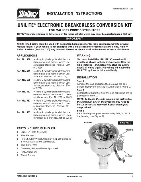
Step 1<br />
Remove the cap and rotor, then remove the condenser.<br />
Remove the plastic insulators (see Figure 1).<br />
Step 2<br />
Loosen the 2 nuts that hold the cap clips/brackets in<br />
place (see Figure 1).<br />
NOTE: To loosen the nuts on a marine distributor,<br />
the aluminum pins in the brackets may need to<br />
be cut in two and removed. Replacement pins<br />
are provided.<br />
Step 3<br />
Remove the point plate assembly by lifting it out of<br />
the housing (see Figure 1).<br />
Point Plate<br />
Cap Clip Nuts<br />
FIGURE 1<br />
Insulators<br />
Condenser<br />
MALLORY IGNITION www.mrgasket.com 1
Step 4<br />
Use a 2-arm or 3-arm puller and the thrust button<br />
(provided) to remove the cam from the rotor sleeve<br />
(see Figure 2).<br />
WARNING: Do not try to remove the cam by<br />
prying on it with a screwdriver(s). This will<br />
damage the advance assembly.<br />
Step 5<br />
Install the UNILITE ® plate assembly into the housing.<br />
Make sure that the cut-out in the plate is directly<br />
below the hole in the housing where the wires will exit<br />
(see Figure 3).<br />
Step 6<br />
Tighten the two nuts that hold the cap clips/brackets<br />
in place. This also secures the UNILITE ® plate.<br />
Step 7<br />
Marine Distributors Only<br />
Replace the cap clips using the new aluminum pins<br />
provided.<br />
Step 8<br />
Install the wire grommet. Lubricate the wires with light<br />
oil. Run the wires through the grommet and out of the<br />
distributor housing (see Figure 3).<br />
Step 9<br />
Install the connector onto the wires. Be sure the wires<br />
are in the correct positions (see Figure 4).<br />
Step 10<br />
Install the rotor/shutter wheel assembly. Make sure<br />
that the rotor is fully seated and that it does not rub<br />
the module wires. Replace the cap.<br />
Step 11<br />
If you removed the distributor to install the UNILITE ®<br />
<strong>Conversion</strong> <strong>Kit</strong>, reinstall the distributor in the engine.<br />
Step 12<br />
Connect the wire harness to the connector. Connect<br />
the 3 wires to the correct locations, as shown in<br />
Figures 5 and 6.<br />
Step 13<br />
Set the ignition timing. Start the engine and recheck<br />
timing.<br />
2<br />
FIGURE 4<br />
Red<br />
Brown<br />
Green<br />
Female Connector<br />
Index Rib<br />
▼<br />
Distributor Wire Harness<br />
Red<br />
Brown<br />
Green<br />
FIGURE 2<br />
FIGURE 3<br />
Grommet<br />
Connector<br />
Puller<br />
Thrust Button<br />
Remove button<br />
after cam has<br />
been removed<br />
MALLORY TECHNICAL SUPPORT (216)688-8300 www.mrgasket.com<br />
Cam<br />
UNILITE® Plate<br />
Assembly
<strong>Ignition</strong> Module<br />
Female Connector<br />
FIGURE 5<br />
12V/<strong>Ignition</strong><br />
Switch<br />
NOTE: The purpose of an ignition ballast<br />
resistor between the ignition switch (12V)<br />
and the ignition coil positive terminal is to<br />
restrict current flow through the ignition<br />
coil. Failure to use an ignition ballast<br />
resistor will eventually destroy the <strong>Ignition</strong><br />
Module.<br />
EXCEPTION: If your vehicle is equipped<br />
with a HYFIRE ® Electronic <strong>Ignition</strong> Control<br />
or similar aftermarket ignition control, use<br />
the wiring procedures stated in the instructions<br />
included with the ignition control.<br />
<strong>Ignition</strong> Module<br />
Female Connector<br />
Distributor Wire Harness<br />
Part No. 29349<br />
MARINE APPLICATIONS: See Page 4 for additional wiring information.<br />
12V/<strong>Ignition</strong><br />
Switch<br />
NOTE: The purpose of loom resistance<br />
wire between the ignition switch (12V) and<br />
the ignition coil positive terminal is to<br />
restrict current flow through the ignition<br />
coil. Failure to use an ignition ballast<br />
resistor will eventually destroy the <strong>Ignition</strong><br />
Module.<br />
EXCEPTION: If your vehicle is equipped<br />
with a HYFIRE ® Electronic <strong>Ignition</strong> Control<br />
or similar aftermarket ignition control, use<br />
the wiring procedures stated in the instructions<br />
included with the ignition control.<br />
Engine<br />
Ground<br />
Distributor Wire Harness<br />
Part No. 29349<br />
Engine<br />
Ground<br />
All other wires originally connected<br />
to the coil (+) terminal<br />
Brown<br />
Brown<br />
MALLORY TECHNICAL SUPPORT (216)688-8300 www.mrgasket.com<br />
Red<br />
<strong>Ignition</strong> Ballast<br />
Resistor<br />
Green<br />
To prevent false triggering and possible<br />
premature ignition failure, you must use<br />
suppression type (carbon core, spiral<br />
core, or radio suppression core) spark<br />
plug wire.<br />
DO NOT USE SOLID CORE (COPPER<br />
CORE OR STAINLESS STEEL CORE)<br />
SPARK PLUG WIRE WITH ANY<br />
ELECTRONIC IGNITION SYSTEM.<br />
All other wires originally connected<br />
to the coil (+) terminal<br />
Red<br />
Loom Resistance<br />
Wire<br />
Green<br />
To prevent false triggering and possible<br />
premature ignition failure, you must use<br />
suppression type (carbon core, spiral<br />
core, or radio suppression core) spark<br />
plug wire.<br />
DO NOT USE SOLID CORE (COPPER<br />
CORE OR STAINLESS STEEL CORE)<br />
SPARK PLUG WIRE WITH ANY<br />
ELECTRONIC IGNITION SYSTEM.<br />
FIGURE 6<br />
3
FOR MARINE USE ONLY<br />
After installing your <strong>Mallory</strong> Electronic Distributor,<br />
the Electronic Shift Assist (ESA) circuit in your boat<br />
must be function tested.Shifting into or out of gear<br />
can be difficult or impossible if the ESA circuit is<br />
malfunctioning or missing. If you encounter shifter<br />
related problems with your boat after installing any<br />
<strong>Mallory</strong> distributor, contact the <strong>Mallory</strong> Technical<br />
Service Department at 216.688.8300.<br />
FIGURE 7<br />
FROM COIL (–) TERMINAL<br />
GRAY WIRE<br />
SOLDER AND INSULATE<br />
2 EA. 400V 3A DIODES IN SERIES<br />
(RADIO SHACK PART NO. 276-1144)<br />
NOTE POSITION OF BANDS ON DIODES<br />
MALLORY IS A DIVISION OF THE MR. GASKET PERFORMANCE GROUP<br />
10601 MEMPHIS AVE. #12, CLEVELAND, OH 44144<br />
216.688.8300 FAX 216.688.8306<br />
All <strong>Mallory</strong> Marine Electronic <strong>Ignition</strong> Systems in<br />
Outboard Marine Corp (OMC) applications with a shift<br />
box require the gray wire from the coil to the shift box<br />
be modified as follows:<br />
The gray wire from the coil (–) terminal triggers<br />
the shift box. The gray wire should be cut or<br />
disconnected at the coil terminal so that the<br />
components shown here can be inserted. Solder<br />
all connections and confirm correct operation,<br />
then insulate well, especially if the boat is being<br />
used in salt water.<br />
SOLDER AND INSULATE<br />
2 EA. 4.7K, 1/2W RESISTORS IN PARALLEL<br />
(RADIO SHACK PART NO. 271-1124<br />
TO SHIFT BOX<br />
TO ENGINE<br />
GROUND<br />
FORM 1466<br />
(REV. D) 10/03<br />
Made in U.S.A.<br />
Printed in U.S.A.<br />
4 www.mrgasket.com


