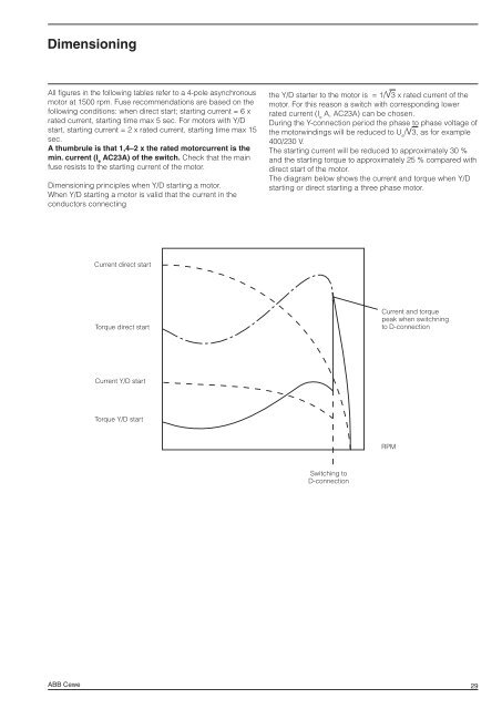
Dimensioning All figures in the following tables refer to a 4-pole asynchronous motor at 1500 rpm. Fuse recommendations are based on the following conditions: when direct start; starting current = 6 x rated current, starting time max 5 sec. For motors with Y/D start, starting current = 2 x rated current, starting time max 15 sec. A thumbrule is that 1,4–2 x the rated motorcurrent is the min. current (I e AC23A) of the switch. Check that the main fuse resists to the starting current of the motor. Dimensioning principles when Y/D starting a motor. When Y/D starting a motor is valid that the current in the conductors connecting ABB Cewe Current direct start Torque direct start Current Y/D start Torque Y/D start the Y/D starter to the motor is = 1/V3 x rated current of the motor. For this reason a switch with corresponding lower rated current (I e A, AC23A) can be chosen. During the Y-connection period the phase to phase voltage of the motorwindings will be reduced to U e /V3, as for example 400/230 V. The starting current will be reduced to approximately 30 % <strong>and</strong> the starting torque to approximately 25 % compared with direct start of the motor. The diagram below shows the current <strong>and</strong> torque when Y/D starting or direct starting a three phase motor. Switching to D-connection Current <strong>and</strong> torque peak when switchning to D-connection RPM 29
Dimensioning <strong>Switches</strong> type BE, BW, <strong>Safety</strong> switches BWS Plastic enclosure, IP 54 or IP 65 I e AC23A 16–90A, 400–690V, 3–45 kW List no see BE, BW, pages 2:3–4, BWS (Y) pages 2:5–6. Motor ratings Direct start Y/D-start Power Operating Rated Fuse Type Type Fuse Type kW voltage current A A 30 V A <strong>Safety</strong> switch Switch <strong>Safety</strong> switch 3 400 6,5 16 T 1) BWS 316, 616 (Y) BW, BE 325, 625 10 T BWS 616 (Y) 500 5,2 10 T BWS 316, 616 (Y) BW, BE 325, 625 10 T BWS 616 (Y) 690 3,8 6 BWS 316, 616 (Y) BW, BE 325, 625 4 BWS 616 (Y) 4 400 8,6 20 T BWS 316, 616 (Y) BW, BE 325, 625 16 T BWS 616 (Y) 500 6,9 16 T BWS 316, 616 (Y) BW, BE 325, 625 10 T BWS 616 (Y) 690 5,2 10 BWS 316, 616 (Y) BW, BE 325, 625 6 BWS 616 (Y) 5,5 400 11,1 25 T BWS 316, 616 (Y) BW, BE 325, 625 20 T BWS 616 (Y) 500 8,9 20 T BWS 316, 616 (Y) BW, BE 325, 625 16 T BWS 616 (Y) 690 6,4 16 BWS 316, 616 (Y) BW, BE 340, 663 10 BWS 616 (Y) 7,5 400 14,8 35 T BWS 325 (Y), 636 (Y) BW, BE 340, 663 25 T BWS 616 (Y) 500 11,8 25 T BWS 316, 616 (Y) BW, BE 325, 625 20 T BWS 616 (Y) 690 8,6 16 BWS 325, 636 (Y) BW, BE 340, BW 663 10 BWS 616 (Y) 11 400 22 35 T BWS 336, 636 (Y) BW, BE 363, BW 663 35 T BWS 636 (Y) 500 17,6 35 T BWS 325, 636 (Y) BW, BE 340, BW 663 25 T BWS 616 (Y) 690 12,8 25 BWS 336, 636 (Y) BW, BE 363, BW 663 16 BWS 616 (Y) 15 400 29 50 T BWS 0336, 636(Y) BW, BE 363, BW 663 35 T BWS 636 (Y) 500 23,2 35 T BWS 336, 636(Y) BW, BE 363, 663BW663 35 T BWS 636 (Y) 690 16,8 25 BWS 336, 636(Y) BW, BE 363, BW 663 20 BWS 636 (Y) 18,5 400 37,0 63 T BWS 336, 636 (Y) BW, BE 363, BW 6100 50 T BWS 636 (Y) 500 29,6 50 T BWS 336, 636 (Y) BW, BE 363 BW 663 35 T BWS 636 (Y) 690 21,5 35 BWS 3100 (Y) BW, BE 3125 25 BWS 636 (Y) 22 400 42 63 T BWS 363, 663 (Y) BW, BE 3100, BW 6100 50 T BWS 636 (Y) 500 33,6 63 T BWS 363, 663 (Y) BW, BE 3100, BW 6100 50 T BWS 363 (Y) 690 24,4 35 BWS 3100 (Y) BW, BE 3125 35 BWS 636 (Y) 30 400 56 80 BWS 3100 (Y) BW, BE 3125 63 T BWS 636 (Y) 500 45 63 T BWS 3100 (Y) BW, BE 3125 50 T BWS 636 (Y) 690 32 50 BWS 3100 (Y) BW, BE 3125 35 2xBWS 3100 (Y) 37 400 68 100 BWS 3100 (Y) BW, BE 3125 80 BWS 663 (Y) 500 55 80 BWS 3100 (Y) BW, BE 3125 63 T BWS 636(Y) 690 39 63 BWS 3100 (Y) BW, BE 3125 50 2xBWS 3100 45 400 83 125 – 2) – 100 BWS 663 500 66 100 – – 2) 80 BWS 66 690 48 63 – – 63 2xBWS 3100 1) “T” = Diazed fuse slow. 2) For motor ratings 45 kW see page 32 ABB Cewe
- Page 1 and 2: Enclosed Switches and Safety Switch
- Page 3 and 4: General information ABB Cewe, Swede
- Page 5 and 6: General information Placement recom
- Page 7 and 8: Description Switches type BE and BW
- Page 9 and 10: Ratings IEC 60 947-3 Double pole ve
- Page 11 and 12: Ratings IEC 60 947-3 Safety switche
- Page 13 and 14: 12 BE 225, 325, 425 BE 625 BE 340,
- Page 15 and 16: 14 BWS 316 BWS 616 BWS 325 BWS 336,
- Page 17 and 18: 16 H 11 H 12 OA 1G10 OA 1G01 L6 Acc
- Page 19 and 20: Dimensions Switches type BE, BW and
- Page 21 and 22: 20 KSE 225, 240 KSE 325, 340, 440 K
- Page 23 and 24: 22 KSA 316, 325 LBAS 336, 363 LBAS
- Page 25 and 26: 24 Membrane gland-sealing plug Cabl
- Page 27 and 28: 26 KSF 225, 325, 425 KSF 340, 440 F
- Page 29: 28 Installation accessories 1) Memb
- Page 33 and 34: Dimensioning Safety switches type L