Evaluation of Minimum Stability Requirements for Ships in Following ...
Evaluation of Minimum Stability Requirements for Ships in Following ...
Evaluation of Minimum Stability Requirements for Ships in Following ...

You also want an ePaper? Increase the reach of your titles
YUMPU automatically turns print PDFs into web optimized ePapers that Google loves.
<strong>Evaluation</strong> <strong>of</strong> <strong>M<strong>in</strong>imum</strong> <strong>Stability</strong> <strong>Requirements</strong> <strong>for</strong> <strong>Ships</strong> <strong>in</strong><br />
Follow<strong>in</strong>g Seas tak<strong>in</strong>g <strong>in</strong>to account Dynamic Effects<br />
Stefan Krüger<br />
Hamburg University <strong>of</strong> Technology (TUHH), Institute <strong>of</strong> Ship Design and Ship Safety<br />
Zusammenfassung<br />
Florian Kluwe<br />
Flensburger Schiffbau-Gesellschaft mbH & Co. KG<br />
In den vergangenen Jahren haben zahlreiche Unfälle von Schiffen, ausgelöst durch das Auftreten großer<br />
Rollw<strong>in</strong>kel, gezeigt, dass die Intaktstabilität nach wie vor e<strong>in</strong> sicherheitsrelevantes Thema ist. E<strong>in</strong>e Möglichkeit<br />
die komplexen Versagensmechanismen basierend auf Stabilitätsschwankungen im Seegang zu analysieren bieten<br />
heutzutage numerische Bewegungssimulationen, die <strong>in</strong>zwischen das Seegangsverhalten von Schiffen h<strong>in</strong>reichend<br />
genau wiedergeben können. Basierend auf numerischen Simulationen ist e<strong>in</strong> Bewertungskonzept für Schiffe <strong>in</strong><br />
längslaufendem Seegang entwickelt worden. Der "Insufficient <strong>Stability</strong> Event Index" (ISEI) bewertet das<br />
Auftretensrisiko von großen Rollw<strong>in</strong>keln. Die grundlegende Idee des Kriteriums beruht darauf, für potentiell<br />
gefährliche Betriebssituationen numerische Simulationen durchzuführen. Die Ergebnisse werden dann mit dem<br />
"Blume-Kriterium" ausgewertet, welches zwischen "sicheren" und "unsicheren" Betriebsbed<strong>in</strong>gungen<br />
unterscheidet. Alle unsicheren Betriebssituationen tragen zum Index bei. Darüber h<strong>in</strong>aus ist e<strong>in</strong>e vere<strong>in</strong>fachte<br />
Bewertungsmethodik entwickelt worden, die unabhängig von numerischen Simulationen ist. Dieser Ansatz<br />
basiert ausschließlich auf hydrostatischen Berechnungen und gilt nur für Schiffe <strong>in</strong> nachlaufendem Seegang. Der<br />
Artikel gibt e<strong>in</strong>en Überblick über die Funktionsweise beider Ansätze und gibt E<strong>in</strong>blick <strong>in</strong> die bisher<br />
durchgeführte Validierung der Kriterien.<br />
Summary<br />
Several accidents <strong>of</strong> ships related to large amplitude roll motions <strong>in</strong> the last years have put <strong>in</strong>tact stability on the<br />
agenda <strong>of</strong> critical safety issues. One way to approach the complex failure modes, <strong>in</strong>itiated by stability alterations<br />
<strong>in</strong> waves, are numerical motion simulations, which nowadays are able to calculate the ship response <strong>in</strong> waves<br />
sufficiently accurate. Based on the numerical simulations, an evaluation concept <strong>for</strong> ships travell<strong>in</strong>g <strong>in</strong> head and<br />
follow<strong>in</strong>g seas was developed. The <strong>in</strong>sufficient stability event <strong>in</strong>dex (ISEI) addresses the risk <strong>of</strong> occurrence <strong>of</strong><br />
dangerous situations related to roll<strong>in</strong>g. The basic idea beh<strong>in</strong>d the criterion is, to carry out numerical simulations<br />
<strong>for</strong> a range <strong>of</strong> potentially dangerous operat<strong>in</strong>g conditions. The results are evaluated with the Blume criterion,<br />
which classifies situations as “safe” or “unsafe”, respectively. All “unsafe” situations contribute to the <strong>in</strong>dex<br />
value. Additionally a “simplified” method was developed to dist<strong>in</strong>guish between “safe” and “unsafe” operat<strong>in</strong>g<br />
conditions, omitt<strong>in</strong>g the need <strong>for</strong> numerical simulations.<br />
This approach is purely based on hydrostatic calculations and is valid <strong>for</strong> ships travell<strong>in</strong>g <strong>in</strong> follow<strong>in</strong>g seas. The<br />
paper gives an overview on the <strong>in</strong>sufficient stability event <strong>in</strong>dex <strong>in</strong> the simulation based <strong>for</strong>m as well as <strong>in</strong> the<br />
simplified version and gives <strong>in</strong>sight <strong>in</strong>to the validation carried out so far.
Introduction<br />
As a consequence <strong>of</strong> accidents a number <strong>of</strong> capsiz<strong>in</strong>g criteria have been proposed <strong>in</strong> the last decades, either<br />
based on model tests and simulations or on empirical observations. All presented criteria <strong>in</strong>tend to reduce the<br />
capsize-risk <strong>of</strong> ships <strong>in</strong> heavy weather. Most <strong>of</strong> these criteria do not take <strong>in</strong>to account dynamic effects <strong>of</strong> ships<br />
travel<strong>in</strong>g <strong>in</strong> a rough seaway directly, but by identify<strong>in</strong>g certa<strong>in</strong> significant parameters which <strong>in</strong>fluence the ship’s<br />
seakeep<strong>in</strong>g behavior.<br />
New techniques such as numerical motion simulations <strong>in</strong> the time doma<strong>in</strong> provide the possibility <strong>of</strong> direct<br />
assessment <strong>of</strong> ship responses <strong>in</strong> waves. Today, this allows us to address exactly those dynamic aspects directly,<br />
which most <strong>of</strong> the older criteria are lack<strong>in</strong>g. This seems to be necessary as modern hull designs seem to be even<br />
more endangered by phenomena like parametric roll than traditional designs. Moreover, the mean ship size and<br />
speed have <strong>in</strong>creased <strong>in</strong> the last decades. This also contributes to the fact that the current <strong>in</strong>tact stability rules are<br />
not able to guarantee a sufficient safety level <strong>for</strong> all ships.<br />
Based on the experience ga<strong>in</strong>ed <strong>in</strong> a number <strong>of</strong> research projects with respect to the applicability <strong>of</strong> numerical<br />
simulations on the evaluation <strong>of</strong> ship motions <strong>in</strong> waves, a new concept <strong>for</strong> a stability criterion was developed,<br />
called Insufficient <strong>Stability</strong> Event Index (ISEI).<br />
For the calibration and the statistical evaluation <strong>of</strong> the new criterion a database <strong>of</strong> 176 ships <strong>in</strong> total is available.<br />
Each <strong>of</strong> these ships has been <strong>in</strong>vestigate <strong>in</strong> at least three different loadcases. One equals the <strong>in</strong>tact stability limit<br />
set by the actual requirements accord<strong>in</strong>g to the IMO Res. A.749, the code on <strong>in</strong>tact stability. The two other<br />
loadcases have 0.5 meters and 1.0 meters larger GM-values, respectively.<br />
For the validation and the determ<strong>in</strong>ation <strong>of</strong> a threshold value, the new <strong>in</strong>dex has been tested with a number <strong>of</strong><br />
real capsiz<strong>in</strong>g accidents, which were re-<strong>in</strong>vestigated from the orig<strong>in</strong>al data available from the accident<br />
<strong>in</strong>vestigation. The load<strong>in</strong>g condition the ship had at the time <strong>of</strong> the accident, which always can be clearly<br />
identified as “not safe”, was analysed with a set <strong>of</strong> <strong>in</strong>tact stability criteria, <strong>in</strong>clud<strong>in</strong>g the new <strong>in</strong>dex. F<strong>in</strong>ally an<br />
attempt was made to identify the stability <strong>in</strong>crease necessary to omit the <strong>in</strong>dividual accidents.<br />
F<strong>in</strong>ally a simplified approach, follow<strong>in</strong>g the same concept as the simulation based criterion, but omitt<strong>in</strong>g the<br />
necessity <strong>of</strong> per<strong>for</strong>m<strong>in</strong>g numerical simulations is derived from the results obta<strong>in</strong>ed from the simulations. Here,<br />
the <strong>in</strong>tention is to provide a simple and easy to use methodology which addresses the dynamic phenomena other<br />
criteria are lack<strong>in</strong>g without the need to per<strong>for</strong>m time and know-how <strong>in</strong>tensive seakeep<strong>in</strong>g simulations.<br />
<strong>Evaluation</strong> <strong>of</strong> Ship Motions by Numerical Simulations<br />
At the end <strong>of</strong> the last decade, after some <strong>in</strong>cidents with conta<strong>in</strong>er vessels have become known that were related<br />
to parametric roll<strong>in</strong>g, a German research group was established to develop dynamic stability criteria, which<br />
should be based on numerical simulations. The simulation code ROLLS, orig<strong>in</strong>ally developed by Kröger, P.<br />
(1987) and Petey, F (1988), was chosen to serve as basis <strong>for</strong> the evaluation <strong>of</strong> seakeep<strong>in</strong>g related problems. The<br />
code was validated and further enhanced by Cramer, H. and Krueger S. (2005) and subsequently <strong>in</strong>tegrated <strong>in</strong>to<br />
the ship design system E4, why this enhanced version <strong>of</strong> the orig<strong>in</strong>al code is known as E4-ROLLS today.<br />
Research programs, funded by the German M<strong>in</strong>istry <strong>for</strong> Education and Research (BMBF), were established.<br />
With<strong>in</strong> this framework, a large number <strong>of</strong> model tests <strong>for</strong> different modern hull <strong>for</strong>ms were carried out <strong>in</strong> tailored<br />
wave sequences to validate the simulation code. It was concluded that the ROLLS-approach was able to predict<br />
the most relevant phenomena related to the problem <strong>of</strong> <strong>in</strong>sufficient stability <strong>in</strong> waves with sufficient accuracy.<br />
Based on these f<strong>in</strong>d<strong>in</strong>gs it was decided to develop a concept <strong>for</strong> m<strong>in</strong>imum stability, based exclusively on<br />
numerical motion simulations. Summ<strong>in</strong>g up the most important results from the research work <strong>of</strong> the past years<br />
follow<strong>in</strong>g conclusions can be drawn:<br />
• Both model tests and simulations confirmed that critical situations endanger<strong>in</strong>g the ship with<br />
respect to large roll amplitudes are observed <strong>in</strong> head as well as follow<strong>in</strong>g seas.<br />
• No capsiz<strong>in</strong>g events were found <strong>in</strong> beam seas at zero speed.<br />
• The most dangerous scenarios appeared to be those where the ship was travel<strong>in</strong>g <strong>in</strong> follow<strong>in</strong>g seas.<br />
• In head seas, large roll<strong>in</strong>g angles were observed, but capsiz<strong>in</strong>g usually did not occur. This is due to<br />
the fact that critical resonances are connected to relatively low values <strong>of</strong> GM <strong>in</strong> follow<strong>in</strong>g seas, and<br />
to high GM values <strong>in</strong> head seas. The model tests were conducted close to potentially critical<br />
resonances.<br />
In contrast to the expectations <strong>of</strong> previous authors, wavelengths significantly shorter than the ship length also<br />
could endanger the vessel whereas wavelengths significantly larger than ship length did not <strong>in</strong>itiate large roll<br />
amplitudes.
<strong>Evaluation</strong> Strategy – The Insufficient <strong>Stability</strong> Event Index (ISEI)<br />
In contradiction to previous criteria, it was decided to determ<strong>in</strong>e all possible scenarios that may lead to a<br />
dangerous situation, but not to quantify how dangerous a specific situation actually is. When def<strong>in</strong><strong>in</strong>g limit<strong>in</strong>g<br />
stability values, it is <strong>of</strong> importance to assess the probability <strong>of</strong> a specific load<strong>in</strong>g condition be<strong>in</strong>g dangerous <strong>for</strong><br />
the vessel, or not. For this application it is not <strong>of</strong> practical <strong>in</strong>terest to get the exact capsiz<strong>in</strong>g rate dur<strong>in</strong>g the<br />
simulation but it is important to know only if the ship did fail. For this, a methodology seems to be most suitable,<br />
which dist<strong>in</strong>guishes between safe or unsafe <strong>in</strong> a specific situation without count<strong>in</strong>g the actual up-cross<strong>in</strong>g rates.<br />
Given such a methodology is available the total long term probability <strong>for</strong> a dangerous situation happen<strong>in</strong>g <strong>in</strong> a<br />
specific load<strong>in</strong>g condition can be def<strong>in</strong>ed then by the <strong>in</strong>sufficient stability event <strong>in</strong>dex (ISEI), which is def<strong>in</strong>ed<br />
by the follow<strong>in</strong>g equation (see also Krueger, S. and Kluwe, F. (2006)):<br />
∞ ∞ v<br />
ISEI =<br />
= 0 = 0<br />
C<br />
2π<br />
T H μ=<br />
0 v<br />
1 1/<br />
3 s<br />
fail<br />
(H<br />
max<br />
∫ ∫ ∫ ∫<br />
p<br />
= v<br />
1/<br />
3<br />
m<strong>in</strong><br />
sea<br />
, T<br />
1<br />
(H<br />
1/<br />
3<br />
, μ, v<br />
s<br />
, T ) ⋅ p ( μ ) ⋅ p (v | H , T , μ ) ⋅<br />
1<br />
) dv<br />
s<br />
dμ dH<br />
Here psea denotes the probability density <strong>of</strong> occurrence <strong>for</strong> a specific seastate def<strong>in</strong>ed by the significant wave<br />
height H1/3 and the characteristic period T1. The two-dimensional probability density <strong>for</strong> the seastate is<br />
calculated from a scatter table presented by Söd<strong>in</strong>g, H. (2001). Further, pμ(μ) denotes the probability density that<br />
the ship is travel<strong>in</strong>g at a course <strong>of</strong> μ-degrees relative to the dom<strong>in</strong>at<strong>in</strong>g wave propagation. It is assumed that pμ(μ)<br />
is <strong>in</strong>dependent from the actual values <strong>of</strong> H1/3 and T1. pμ(μ) can be taken from full scale observations (see<br />
Krueger, S. , H<strong>in</strong>richs, R., Kluwe F. and Billerbeck, H. (2006)) and is assumed to be equally distributed <strong>in</strong> the<br />
present context. Then pv(H1/3,T1,μ,vs) denotes the probability density that the ship is travel<strong>in</strong>g at a speed <strong>of</strong> vs<br />
knots. As pμ(μ) is selected <strong>in</strong>dependently from the seastate, pv(,vs|H1/3,T1,μ) is a conditional probability depend<strong>in</strong>g<br />
on all four parameters, as not all speeds are physically possible <strong>in</strong> a specific situation. Krueger, S. , H<strong>in</strong>richs, R.,<br />
Kluwe F. and Billerbeck, H. (2006) determ<strong>in</strong>e the maximum possible ship speed <strong>in</strong> the given environmental<br />
conditions at full eng<strong>in</strong>e output and the m<strong>in</strong>imum speed at eng<strong>in</strong>e idle speed from systematic propulsion<br />
calculations. With<strong>in</strong> the range <strong>of</strong> possible speeds [vm<strong>in</strong>,vmax] the probability <strong>of</strong> occurrence is assumed to be<br />
l<strong>in</strong>early distributed, based on the experience that masters tend to ma<strong>in</strong>ta<strong>in</strong> the speed as high a possible and<br />
justifiable. The m<strong>in</strong>imum speed is chosen at such level that it represents the m<strong>in</strong>imum speed which is required to<br />
ma<strong>in</strong>ta<strong>in</strong> the maneuverability <strong>of</strong> the ship.<br />
1/<br />
3<br />
v<br />
dT<br />
Figure 1: Speed probability distribution<br />
The failure coefficient Cfail(H1/3,T1,μ,vs) is a saltus function which takes the value 0 <strong>for</strong> all situations considered<br />
to be safe and 1 <strong>for</strong> all un-safe situations. It is determ<strong>in</strong>ed from the time series obta<strong>in</strong>ed from numerical<br />
simulation by apply<strong>in</strong>g the Blume-criterion.<br />
Blume developed this criterion to evaluate the ship safety with respect to capsiz<strong>in</strong>g <strong>in</strong> follow<strong>in</strong>g and stern<br />
quarter<strong>in</strong>g seas by model tests. For each run dur<strong>in</strong>g the model test the maximum roll angle is registered. Then the<br />
residual area ER below the still water lever arm is calculated, limited by the maximum roll angle and the po<strong>in</strong>t <strong>of</strong><br />
vanish<strong>in</strong>g stability (see Figure 2). If the ship capsizes dur<strong>in</strong>g the run, ER is set to zero. F<strong>in</strong>ally a ship is regarded<br />
as safe aga<strong>in</strong>st capsiz<strong>in</strong>g if it fulfills the follow<strong>in</strong>g requirement:<br />
μ<br />
1<br />
s<br />
1/<br />
3<br />
E R − 3 σ > 0<br />
[2]<br />
Here R E denotes the residual area averaged by all runs, σ represents the standard deviation <strong>of</strong> ER. By apply<strong>in</strong>g<br />
1<br />
[1]
the criterion, a stability limit, represented by either a m<strong>in</strong>imum GM or by a limit<strong>in</strong>g maximum wave height can<br />
be determ<strong>in</strong>ed.<br />
Figure 2: Residual area below the right<strong>in</strong>g leer curve<br />
Although developed orig<strong>in</strong>ally <strong>for</strong> the evaluation <strong>of</strong> model tests, Blumes approach has proven to be also a<br />
suitable measure <strong>for</strong> ship safety <strong>in</strong> connection with numerical simulations. The statistical reliability <strong>of</strong> the<br />
criterion is expected to be even higher <strong>in</strong> this case, as the time series obta<strong>in</strong>ed from simulations usually are much<br />
longer than model test runs.<br />
In some cases where the Blume-criterion does not deliver suitable results, typically due to large angles <strong>of</strong><br />
vanish<strong>in</strong>g stability, the occurrence <strong>of</strong> a certa<strong>in</strong> maximum roll angle may be taken <strong>in</strong>to account simultaneously.<br />
The more conservative value is taken <strong>for</strong> the decision between “safe” and “unsafe”. The results may be plotted <strong>in</strong><br />
<strong>for</strong>m <strong>of</strong> polar diagrams as presented <strong>in</strong> Figure 3. Each polardiagram shows the limit<strong>in</strong>g wave heights <strong>for</strong> a<br />
specific significant period (or the related significant deep water wave length), giv<strong>in</strong>g an overview about critical<br />
situations (see Cramer, H. and Krueger S. (2005) and Krueger, S. (2002)).<br />
All situations where the failure criterion is set to 1 contribute to the overall <strong>in</strong>dex, weighted with the overall<br />
probability <strong>of</strong> occurrence <strong>of</strong> the <strong>in</strong>dividual operational cells. An operational cell <strong>in</strong> this context always is def<strong>in</strong>ed<br />
by load<strong>in</strong>g condition, speed, head<strong>in</strong>g, wave length and wave height.<br />
Depend<strong>in</strong>g on whether the ship is travell<strong>in</strong>g <strong>in</strong> head, beam or follow<strong>in</strong>g seas different failure mechanisms can<br />
lead to large roll angles or and capsiz<strong>in</strong>g. To get more accurate <strong>in</strong><strong>for</strong>mation on which failure modes actually lead<br />
to the failure <strong>of</strong> a ship, it seems to be useful to split the ISEI <strong>in</strong> a head sea, a beam sea and a follow<strong>in</strong>g sea <strong>in</strong>dex.<br />
A further step is to discretise Equation [1] as the probability <strong>of</strong> occurrence <strong>of</strong> a specific sea state as well as the<br />
failure coefficient Cfail are available as discrete values <strong>for</strong> the <strong>in</strong>dividual operational cells. The <strong>in</strong>sufficient<br />
stability event <strong>in</strong>dex ISEI then can be written as follows:<br />
ISEI =<br />
∑<br />
head , beam,<br />
follow<strong>in</strong>g<br />
⎡<br />
⎢<br />
⎢<br />
⎢<br />
⎣C<br />
max<br />
∑∑ ∑ ∑<br />
T<br />
1<br />
H<br />
1/<br />
3<br />
μ=<br />
μ m<strong>in</strong> v<br />
s<br />
fail<br />
(H<br />
μmax<br />
1/<br />
3<br />
1<br />
v<br />
δP<br />
= v<br />
, T , μ, v<br />
m<strong>in</strong><br />
s<br />
)<br />
sea<br />
(H<br />
1/<br />
3<br />
, T ) ⋅δP<br />
( μ ) ⋅δP<br />
(v | H<br />
1<br />
μ<br />
v<br />
s<br />
1/<br />
3<br />
⎤<br />
, T1,<br />
μ ) ⋅⎥<br />
⎥<br />
⎥<br />
⎦<br />
Here, the δP denote the cumulated probability <strong>for</strong> the <strong>in</strong>dividual discrete range <strong>of</strong> values. The encounter angles<br />
run from μ=-π/4 to μ=+π/4 <strong>for</strong> the follow<strong>in</strong>g sea cases and from μ=3/4 π to μ=5/4 π <strong>for</strong> head seas. The rest<br />
contributes to the beam seas <strong>in</strong>dex.<br />
The calculation <strong>of</strong> the <strong>in</strong>dex starts with the determ<strong>in</strong>ation <strong>of</strong> the ship responses by time doma<strong>in</strong> simulations.<br />
Typically the simulation is carried out <strong>in</strong> five different realisations <strong>of</strong> a specific seastate, each run represent<strong>in</strong>g<br />
10000 seconds real time.<br />
For the <strong>in</strong>dex we consider contributions <strong>of</strong> six different wave lengths, whereas seven different courses and <strong>in</strong><br />
average 10 to 12 speeds are evaluated <strong>for</strong> each wave length. Wave heights are considered as long as the scatter<br />
table <strong>in</strong>dicates a certa<strong>in</strong> probability <strong>of</strong> occurrence larger than zero. The ISEI contribution <strong>of</strong> each cell is summed<br />
up to the overall <strong>in</strong>dex at the end.<br />
The ISEI-concept allows the identification <strong>of</strong> ship designs and ship types, which are vulnerable <strong>for</strong> <strong>in</strong>sufficient<br />
stability events <strong>in</strong> follow<strong>in</strong>g or head seas. At this the ISEI-concept takes <strong>in</strong>to account all relevant phenomena<br />
occurr<strong>in</strong>g <strong>in</strong> head and follow<strong>in</strong>g seas that may endanger the vessel with respect to m<strong>in</strong>imum stability.<br />
[3]
Figure 3: Graphical visualization <strong>of</strong> dangerous scenarios<br />
by the limit<strong>in</strong>g significant wave height accord<strong>in</strong>g to the<br />
Blume-criterion<br />
Validation <strong>of</strong> the Concept with Real Capsiz<strong>in</strong>g Accidents<br />
Dur<strong>in</strong>g the validation phase the new stability criterion has to show that it is able to identify all un-safe situations<br />
as well as safe situations by deliver<strong>in</strong>g clearly different <strong>in</strong>dex values. To assure a uni<strong>for</strong>m safety level <strong>for</strong> all<br />
ships the criterion additionally shall deliver similar <strong>in</strong>dex values <strong>for</strong> ships with similar ma<strong>in</strong> properties <strong>in</strong> similar<br />
situations.<br />
F<strong>in</strong>ally it has to be assured that the criterion is sufficiently conservative to deliver reliable decisions tak<strong>in</strong>g <strong>in</strong>to<br />
account the uncerta<strong>in</strong>ties <strong>in</strong> the calculation. On the other hand the criterion must not be too conservative as it<br />
then reduces the usability <strong>of</strong> safe ships un-necessarily.<br />
The most realistic benchmark-scenarios are real accidents, why several <strong>of</strong> them have been <strong>in</strong>vestigated dur<strong>in</strong>g<br />
the development <strong>of</strong> the new criterion, where the focus was laid on ships which did capsize <strong>in</strong> heavy weather<br />
without any further damage by collision or ground<strong>in</strong>g.<br />
One very recent example <strong>for</strong> this work is the capsiz<strong>in</strong>g and subsequent s<strong>in</strong>k<strong>in</strong>g <strong>of</strong> the RoRo-vessel FINNBIRCH<br />
<strong>in</strong> the year 2006, which is presented below.<br />
In order to assess the above mentioned tasks the follow<strong>in</strong>g procedure was applied:<br />
� Identification <strong>of</strong> the accident conditions (environmental data, load<strong>in</strong>g condition)<br />
� Application <strong>of</strong> different stability criteria on this situation and evaluation <strong>of</strong> ISEI <strong>for</strong> the given load<strong>in</strong>g<br />
condition<br />
� Estimation <strong>of</strong> a probably safe conditions and application <strong>of</strong> the capsiz<strong>in</strong>g criteria to these situations.<br />
The results <strong>of</strong> our <strong>in</strong>vestigations show that <strong>in</strong> almost cases the stability criteria give a common statement whether<br />
a ship can be considered as safe or un-safe <strong>in</strong> a certa<strong>in</strong> situation. The new stability <strong>in</strong>dex always rated the<br />
accident situations as un-safe. The results from these <strong>in</strong>vestigations were used also to determ<strong>in</strong>e acceptable<br />
threshold values <strong>for</strong> the <strong>in</strong>dex, which are derived later <strong>in</strong> this document.<br />
Example: The Capsiz<strong>in</strong>g <strong>of</strong> MV FINNBIRCH (2006)<br />
On Wednesday, 1st <strong>of</strong> November 2006, the 8500 dwt RoRo-Ferry M/V FINNBIRCH (call sign SLNK) capsized<br />
<strong>in</strong> heavy weather <strong>in</strong> the Baltic Sea between the islands Gotland and Oland. At the time <strong>of</strong> the accident, the vessel<br />
was travel<strong>in</strong>g south at an estimated course <strong>of</strong> about 190- 200 Degree. The vessel was loaded with trailers, <strong>of</strong><br />
which a significant amount was stowed on the top deck (see Figure 4). At the time <strong>of</strong> the accident, the weather<br />
w<strong>in</strong>d was about 20-25m/s or BF9-10. The sea was rough with significant wave heights <strong>of</strong> abt. 5-6m, significant<br />
period about 8-8.5s. These data are obta<strong>in</strong>ed from h<strong>in</strong>dcast sources.
Figure 4: Left hand side: Position, wave encounter and course <strong>of</strong> MV F<strong>in</strong>nbirch at the time <strong>of</strong> the accident. Right<br />
hand side: MV F<strong>in</strong>nbirch <strong>in</strong> <strong>in</strong>termediate float<strong>in</strong>g condition<br />
Accord<strong>in</strong>g to the observations <strong>of</strong> the master <strong>of</strong> M/V MARNEBORG, the vessel closest to the MV FINNBIRCH,<br />
who later coord<strong>in</strong>ated the rescue operations the vessel was roll<strong>in</strong>g significantly. At about 16:15 she heeled to<br />
about 50 degree. The vessel rema<strong>in</strong>ed <strong>in</strong> that <strong>in</strong>termediate equilibrium float<strong>in</strong>g condition <strong>for</strong> a while (see Figure<br />
4), until she f<strong>in</strong>ally capsized at about 19:37.<br />
M/V FINNBIRCH was built <strong>in</strong> 1978. In 1979 the vessel was additionally equipped with side sponsons and <strong>in</strong><br />
1986 an additional weather deck was added. Both conversions have significantly affected the stability <strong>of</strong> the<br />
vessel. The <strong>of</strong>ficial accident <strong>in</strong>vestigation has not been f<strong>in</strong>ished yet, why no <strong>in</strong>vestigation report is available so<br />
far. There<strong>for</strong>e, some assumptions have to be made with respect to the load<strong>in</strong>g condition prior to the accident:<br />
• The additional steel weight <strong>of</strong> the retr<strong>of</strong>itted top deck is ca. 250 tons.<br />
• The top deck was fully loaded with 36 trailers accord<strong>in</strong>g to Figure 4. From this fact we conclude that also<br />
the other decks were almost fully loaded.<br />
• The average trailer weight is assumed to be ca. 23.5 tons.<br />
When M/V FINNBIRCH was delivered <strong>in</strong> 1979, no damage stability regulations were <strong>in</strong> <strong>for</strong>ce, which means that<br />
the stability <strong>of</strong> the vessel was governed by the relevant <strong>in</strong>tact criteria.<br />
The limit<strong>in</strong>g <strong>in</strong>tact stability criterion is most likely hm<strong>in</strong> ( 30°<br />
) ≥ 0.<br />
20m<br />
<strong>for</strong> the vessel <strong>in</strong>clud<strong>in</strong>g the sponsons<br />
and the top deck. Our <strong>in</strong>vestigations show that, <strong>in</strong> case the top deck is fully loaded, the ship operates close to the<br />
<strong>in</strong>tact stability limit. Tak<strong>in</strong>g all assumptions <strong>in</strong>to account we obta<strong>in</strong> the follow<strong>in</strong>g float<strong>in</strong>g condition:<br />
Table 1: Intact float<strong>in</strong>g condition<br />
Total Weight : 13686.000 t<br />
Draft at A.P (moulded) : 6.843 m<br />
Trim (pos. fwd) : -0.078 m<br />
Metacentric Height : 1.704 m<br />
The computed right<strong>in</strong>g levers <strong>in</strong> waves show practically no stability on the wave crest <strong>for</strong> a wave which comes<br />
close to the accident seastate (see Figure 5). It is also important to underl<strong>in</strong>e the fact that the alterations <strong>of</strong> the<br />
<strong>in</strong>itial GM <strong>in</strong> the sea state are substantial, which means that a lot <strong>of</strong> energy is <strong>in</strong>troduced <strong>in</strong>to the vessel by the<br />
sea state.<br />
The speed <strong>of</strong> the vessel is assumed with 16 knots at an encounter angle <strong>of</strong> 30 degree. The results <strong>of</strong> the<br />
numerical simulation show that roll angles up to 40 Degree occur <strong>for</strong> situations when the wave height exceeds<br />
some threshold value and is at the same time <strong>in</strong> phase with the roll motion (Figure 6). Figure 4 shows an<br />
<strong>in</strong>termediate equilibrium float<strong>in</strong>g condition <strong>of</strong> abt. 45-50 degree, which is only possible <strong>in</strong> case cargo has<br />
significantly shifted. Introduc<strong>in</strong>g this cargo shift <strong>in</strong>to the simulation results <strong>in</strong> an <strong>in</strong>termediate equilibrium there<br />
as well (Figure 6, 7350s onwards). In this phase, an additional cargo shift may have taken place or water may<br />
have entered the vessel, which has then lead to the f<strong>in</strong>al loss.
Figure 5: Lever arm curve <strong>of</strong> M/V F<strong>in</strong>nbirch<br />
Figure 6: Simulated time series <strong>of</strong> the accident<br />
Our analysis <strong>in</strong>dicates that the vessel was most probably travel<strong>in</strong>g close to a 1:1 resonance condition at the time<br />
<strong>of</strong> the accident. In this context, it is <strong>in</strong>terest<strong>in</strong>g to note that the actual scenarios which lead to critical resonances<br />
could not be determ<strong>in</strong>ed from the stillwater roll<strong>in</strong>g period <strong>for</strong> small roll angles as the non-l<strong>in</strong>earity <strong>of</strong> the lever<br />
arm curve shifts the natural roll period significantly.<br />
Criterion GM=1.69 m GM=1.89 m<br />
Söd<strong>in</strong>g<br />
Capsize Probability<br />
0.2E-3/Roll Cycle0.2 E-6/Roll Cycle<br />
Blume (Modified) ,<br />
E_R - 3 S<br />
E_R = S = 0 115.099 mmrad<br />
ISEI (direct) 0.01 4.5E-4<br />
Empirical Criteria<br />
Crest lever No positive > 0.1m<br />
Crest range none >30 Deg.<br />
Table 2: Results <strong>for</strong> different capsiz<strong>in</strong>g criteria<br />
From the comparison, it can clearly be seen that all criteria applied to the accident situation, consider the case<br />
where the vessel did actually capsize as dangerous, whereas all criteria show a significant improvement <strong>for</strong> the<br />
case with <strong>in</strong>creased GM. As the accident case has fulfilled all prescribed IMO <strong>in</strong>tact stability criteria, it can be<br />
concluded that the safety level <strong>of</strong> these criteria is not sufficient. Additionally, it can be stated that a direct ISEI <strong>of</strong><br />
0.01 represents a condition which has clearly proven to be unsafe, whereas an ISEI <strong>of</strong> 4.5e-4 represents a<br />
condition which is considered to be safe by all criteria.<br />
Concluded, it can be stated that the dynamic analysis has clearly shown that the reason <strong>for</strong> the loss <strong>of</strong> MV<br />
FINNBIRCH was most probably <strong>in</strong>sufficient stability <strong>in</strong> a follow<strong>in</strong>g sea scenario.
Threshold Values<br />
The question now be<strong>in</strong>g addressed is, at which ISEI values an acceptably high safety level is reached. While the<br />
boundary <strong>of</strong> the safe doma<strong>in</strong> rema<strong>in</strong>s unknown, the ISEI values which are associated to clearly un-safe situations<br />
can be clearly identified by the application <strong>of</strong> the criterion to ships which were lost by capsiz<strong>in</strong>g.<br />
For this purpose a number <strong>of</strong> capsiz<strong>in</strong>g accidents has been re-<strong>in</strong>vestigated accord<strong>in</strong>g to the scheme exemplarily<br />
presented <strong>in</strong> the previous section. Figure 7 gives an overview over the ships <strong>in</strong>vestigated. The ISEI values<br />
calculated <strong>for</strong> the accident load<strong>in</strong>g condition typically lie with<strong>in</strong> the order <strong>of</strong> magnitude <strong>of</strong> 10 -1 . It can be<br />
concluded that such ISEI values clearly represent situations <strong>in</strong> which ships are considered to be un-safe on a not<br />
acceptable level. Start<strong>in</strong>g from this very low safety level, the stability <strong>of</strong> the ships is successively <strong>in</strong>creased to<br />
levels where a set <strong>of</strong> other stability criteria is fulfilled <strong>for</strong> the accident situation. For this load<strong>in</strong>g condition the<br />
ISEI values typically lie below 10 -2 . Figure 7 shows the ISEI values calculated <strong>for</strong> a selection <strong>of</strong> ships <strong>in</strong><br />
different load<strong>in</strong>g conditions, <strong>in</strong>clud<strong>in</strong>g the ships from the <strong>in</strong>vestigated accidents.<br />
The ISEI criterion was further evaluated <strong>for</strong> a large number <strong>of</strong> different ships. Each ship is tested <strong>in</strong> three generic<br />
load<strong>in</strong>g conditions, whereas the first equals the <strong>in</strong>tact stability limit accord<strong>in</strong>g to the IMO Res. A.749. The<br />
second and the third loadcase have GMs <strong>in</strong>creased by 0.5 meters and 1.0 meters, respectively. The second<br />
loadcase roughly lies <strong>in</strong> the region where modern ship types have their stability limit accord<strong>in</strong>g to the damage<br />
stability regulations.<br />
Typically the first loadcase delivers ISEI values <strong>in</strong> the un-safe region (10 -1 ), while the second one typically<br />
delivers values <strong>in</strong> the range between 10 -3 and 10 -2 . The third one mostly is below 10 -3 . Accidents related to large<br />
amplitude roll motions with modern ships travel<strong>in</strong>g with permissible stability, which means at or above the<br />
damage stability limit, are not very frequent, but they do occur more than once per year. On this basis we def<strong>in</strong>e<br />
the region around ISEI values <strong>of</strong> 10 -2 as "critical" region.<br />
There<strong>for</strong>e the follow<strong>in</strong>g threshold values <strong>for</strong> the Insufficient <strong>Stability</strong> Event Index are proposed:<br />
• Values above 5.0E-2 are considered to be un-safe <strong>for</strong> all types <strong>of</strong> ships.<br />
• Values between 1.0E-3 and 5.0E-2 are considered to be potentially dangerous. These values might<br />
be acceptable <strong>for</strong> small ships and <strong>for</strong> ships operat<strong>in</strong>g <strong>in</strong> restricted areas <strong>of</strong> operation.<br />
• Values below 1.0E-3 are considered to be generally safe.<br />
Figure 7: Capsiz<strong>in</strong>g accidents and model tests evaluated <strong>for</strong> the development <strong>of</strong> the ISEI threshold values.
The Simplified Insufficient <strong>Stability</strong> Event Index (ISEIs)<br />
The use <strong>of</strong> seakeep<strong>in</strong>g simulations requires substantial knowledge <strong>in</strong> the field <strong>of</strong> numerical fluid dynamics.<br />
Significant ef<strong>for</strong>t is required <strong>for</strong> sett<strong>in</strong>g up, evaluat<strong>in</strong>g and validat<strong>in</strong>g the numerical simulations. Neither this<br />
special knowledge nor the required time-ef<strong>for</strong>t <strong>for</strong> the detailed analysis <strong>of</strong> ships by means <strong>of</strong> direct simulation<br />
can be presumed to be available <strong>for</strong> all <strong>in</strong>stitutions <strong>in</strong>volved <strong>in</strong> calculat<strong>in</strong>g and approv<strong>in</strong>g ships’ <strong>in</strong>tact stability.<br />
Besides these problems related to the limited access to pr<strong>in</strong>cipally exist<strong>in</strong>g technology, there is another problem<br />
related to lack<strong>in</strong>g standardisation <strong>of</strong> seakeep<strong>in</strong>g simulations. Currently, there is neither an <strong>in</strong>ternational standard<br />
def<strong>in</strong><strong>in</strong>g m<strong>in</strong>imum requirements <strong>for</strong> numerical seakeep<strong>in</strong>g codes employed <strong>for</strong> the assessment <strong>of</strong> dynamic ship<br />
stability, nor any standardised procedure <strong>for</strong> the set up <strong>of</strong> environmental conditions to be used <strong>for</strong> the<br />
simulations. For the practical application <strong>of</strong> a simulation-based criterion this would mean that at first a basic<br />
standard <strong>for</strong> numerical seakeep<strong>in</strong>g simulations had to be established.<br />
Tak<strong>in</strong>g all this <strong>in</strong>to account, a regulation directly and solely depend<strong>in</strong>g on numerical seakeep<strong>in</strong>g simulations<br />
today will hardly be accepted as a standard procedure <strong>for</strong> the assessment <strong>of</strong> the <strong>in</strong>tact stability <strong>of</strong> ships. This<br />
results <strong>in</strong> the need <strong>for</strong> <strong>in</strong>troduc<strong>in</strong>g an alternative approach additionally to the simulation based ISEI-approach.<br />
The simplified approach shall be able to address the same phenomena as the direct one with comparable<br />
reliability and with consistent results, employ<strong>in</strong>g the experiences and f<strong>in</strong>d<strong>in</strong>gs made dur<strong>in</strong>g the simulations.<br />
A simplified, determ<strong>in</strong>istic criterion always addresses only a clearly specified and limited set <strong>of</strong> phenomena or<br />
failure mechanisms. Thus, its applicability must be always limited to a certa<strong>in</strong> set <strong>of</strong> operat<strong>in</strong>g conditions <strong>in</strong><br />
which the ship is endangered by exactly those phenomena covered by the criterion. Failure mechanisms <strong>in</strong> head<br />
and follow<strong>in</strong>g seas are quite different. Although they are related to the dynamic change <strong>of</strong> right<strong>in</strong>g levers <strong>in</strong><br />
waves, the failure scenarios are quite different. In head seas the ship can be excited <strong>in</strong> a certa<strong>in</strong> range <strong>of</strong><br />
encounter periods. This results <strong>in</strong> large roll amplitudes, <strong>of</strong>ten lead<strong>in</strong>g to severe damage to the ship and the cargo<br />
on board. As the encounter frequency <strong>in</strong> head seas is larger than <strong>in</strong> follow<strong>in</strong>g seas, the resonance conditions are<br />
usually met at larger GM values than <strong>in</strong> follow<strong>in</strong>g seas. Additionally the time, the ship faces low stability while<br />
sitt<strong>in</strong>g on the wave crest position is much shorter than <strong>in</strong> follow<strong>in</strong>g seas. Thus, simplified criteria <strong>for</strong> head- and<br />
follow<strong>in</strong>g sea situations must assess different failure scenarios. Our simplified <strong>in</strong>sufficient stability event <strong>in</strong>dex<br />
(ISEIs) targets follow<strong>in</strong>g and stern quarter<strong>in</strong>g sea cases only, as these scenarios more <strong>of</strong>ten lead to the total loss<br />
<strong>of</strong> a ship as head sea <strong>in</strong>cidents and thus have the highest priority to be covered by a suitable criterion. This is<br />
supported clearly by the charts <strong>in</strong> Figure 8, which conta<strong>in</strong> statistical data on <strong>in</strong>tact stability accidents sorted by<br />
wave encounter direction.<br />
Figure 8: Statistical distribution <strong>of</strong> capsiz<strong>in</strong>g accidents after encounter angle <strong>of</strong> waves<br />
One important requirement <strong>for</strong> the simplified criterion is that it has to be consistent with the simulated approach.<br />
This means that the simulated values <strong>for</strong> the ISEIfollow<strong>in</strong>g shall be directly comparable with those obta<strong>in</strong>ed by the<br />
ISEIs approach. For this reason the simplified approach is based on the same <strong>for</strong>mulas as the simulated one. The<br />
only difference can be found <strong>in</strong> the way fail<br />
C is calculated. Like <strong>for</strong> the simulated approach this failure<br />
coefficient takes the value 1 <strong>for</strong> all wave heights exceed<strong>in</strong>g a certa<strong>in</strong> limit<strong>in</strong>g wave height. Here the significant<br />
limit<strong>in</strong>g wave height H1/3 is replaced by a regular, equivalent wave <strong>of</strong> the same height, denoted as "equivalent<br />
significant wave height" (H).<br />
One important observation made from the simulated limit<strong>in</strong>g wave heights is that the limit<strong>in</strong>g wave height<br />
changes only little <strong>for</strong> a given speed over the full range <strong>of</strong> encounter angles <strong>in</strong> the follow<strong>in</strong>g seas – sector (-45°
to 45°). This allows us to <strong>in</strong>troduce another simplification, by determ<strong>in</strong><strong>in</strong>g only a mean limit<strong>in</strong>g wave height,<br />
<strong>in</strong>dependently from the encounter angle. Then the simplified criterion yields:<br />
vmax<br />
∑∑ ∑<br />
S<br />
ISEI = δPsea(H1/ 3 , T1<br />
) ⋅δPμ ( μ ) ⋅δPv<br />
(vs<br />
| H1/<br />
3 , T1,<br />
μ ) ⋅C<br />
fail(H1/<br />
3 , T1<br />
, μ, vs<br />
) [4]<br />
T H v = v<br />
1 1/<br />
3 s<br />
m<strong>in</strong><br />
Here the factor 1/3 was <strong>in</strong>troduced to account <strong>for</strong> the overall course probability <strong>of</strong> the follow<strong>in</strong>g seas-sector. The<br />
equivalent limit<strong>in</strong>g wave height is calculated from a determ<strong>in</strong>istic approach tak<strong>in</strong>g <strong>in</strong>to account two major<br />
parameters <strong>in</strong>fluenc<strong>in</strong>g the behavior <strong>of</strong> the ship <strong>in</strong> follow<strong>in</strong>g and stern quarter<strong>in</strong>g waves. One parameter is the<br />
lever arm alteration the ship has <strong>in</strong> the given wave; the second one is the ratio between the encounter frequency<br />
and the natural roll frequency <strong>of</strong> the ship to account <strong>for</strong> resonance conditions. Then the limit<strong>in</strong>g wave height <strong>for</strong><br />
the equivalent wave can be calculated as follows:<br />
H<br />
lim<br />
⎛ ω<br />
= f ⎜<br />
⎝ ω<br />
e<br />
s<br />
⎞<br />
, Ci<br />
⎟<br />
⋅ C<br />
⎠<br />
C ( ζ ) 11 ⋅ λ<br />
10 A0<br />
[5]<br />
Here ζ A0 denotes the wave steepness factor obta<strong>in</strong>ed from a lever arm balance described <strong>in</strong> the follow<strong>in</strong>g. It is<br />
calculated from the limit<strong>in</strong>g wave height by divid<strong>in</strong>g it through the wave length. The function f addresses the<br />
<strong>in</strong>fluence <strong>of</strong> the frequency ratio e ωs<br />
ω / . Ci, C10 and C11 are correlation factors.<br />
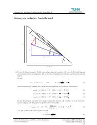
Figure 9: Lever arm balance <strong>in</strong> waves<br />
Figure 9 shows the pr<strong>in</strong>cipal elements <strong>of</strong> the lever arm balance which is used to determ<strong>in</strong>e the mean limit<strong>in</strong>g<br />
wave height. The first step is to calculate the lever arms <strong>in</strong> still water conditions and <strong>in</strong> the given wave <strong>for</strong> the<br />
situations wave crest amidships and wave trough amidships. All situations <strong>in</strong> which the area under the smallest<br />
lever arm curve <strong>in</strong>tegrated up to an angle <strong>of</strong> 40 degrees (A40) is larger than the area between the smallest and the<br />
largest right<strong>in</strong>g arm curve <strong>in</strong>tegrated up to 15 degrees heel (A15). The idea beh<strong>in</strong>d this scenario is that the lever<br />
arm alterations caused by the pass<strong>in</strong>g wave lead to a certa<strong>in</strong> amount <strong>of</strong> energy be<strong>in</strong>g <strong>in</strong>troduced <strong>in</strong>to the ship. In<br />
order to prevent capsiz<strong>in</strong>g, the ship has to be able to compensate this amount <strong>of</strong> energy even with the smallest<br />
right<strong>in</strong>g moments occurr<strong>in</strong>g, when travel<strong>in</strong>g <strong>in</strong> waves. This m<strong>in</strong>imum stability usually is associated with the<br />
wave crest position. To take <strong>in</strong>to account that the ship usually travels <strong>in</strong> irregular and short crested waves we<br />
<strong>in</strong>troduce another energy component which is added to the A15-contribution represent<strong>in</strong>g direct heel<strong>in</strong>g moments<br />
<strong>in</strong>troduced by beam wave components (Aext). Then the mean, speed <strong>in</strong>dependent, limit<strong>in</strong>g wave height is<br />
calculated by:<br />
A0<br />
{ ( ) = 0}<br />
!<br />
H ∈ H | A A + A<br />
[6]<br />
H :=<br />
−<br />
40m<strong>in</strong><br />
15diff<br />
ext
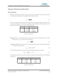
Figure 10: Frequency dependency <strong>of</strong> the limit<strong>in</strong>g wave height<br />
To account <strong>for</strong> the dependency between limit<strong>in</strong>g wave height and the encounter frequency the function f is<br />
determ<strong>in</strong>ed by regression from simulated results. For this purpose the mean limit<strong>in</strong>g wave height from the<br />
simulations over all speeds is calculated. Then, the difference between the actual limit<strong>in</strong>g wave height at a<br />
certa<strong>in</strong> speed and the mean value is determ<strong>in</strong>ed. Figure 10 shows the results <strong>for</strong> all cases <strong>in</strong> our database.<br />
Although the results are scattered significantly the 1:1 and 2:1 resonance conditions are clearly impr<strong>in</strong>ted <strong>in</strong> the<br />
data set. The regression function, shown <strong>in</strong> Figure 10 as green curve is calculated with the follow<strong>in</strong>g approach:<br />
⎧ f 0 ( ωe<br />
/ ωs<br />
, Ci<br />
) <strong>for</strong> ωe<br />
/ ωs<br />
< 2.8<br />
f ( ωe<br />
/ ωs<br />
, Ci<br />
) = ⎨<br />
f ( 2.8, C )<br />
[7]<br />
+ C ⋅ ω / ω <strong>for</strong> ω / ω ≥ 2.8<br />
⎩<br />
0<br />
The function f0 is a comb<strong>in</strong>ation <strong>of</strong> three s<strong>in</strong>e-functions and reads as follows:<br />
f<br />
0<br />
i<br />
9<br />
( ωe<br />
/ ωs<br />
, Ci<br />
) = C1<br />
⋅ s<strong>in</strong>(<br />
2πωe<br />
/ ωs<br />
− C2<br />
⋅ π / 2)<br />
C3<br />
⋅ s<strong>in</strong>(<br />
πωe<br />
/ ωs<br />
− C4<br />
⋅ π / 2)<br />
C5<br />
⋅ s<strong>in</strong>(<br />
C6πωe<br />
/ ωs<br />
− C7<br />
⋅ π / 2)<br />
+ C8<br />
The regression coefficients C1 through C11 are determ<strong>in</strong>ed at the follow<strong>in</strong>g values:<br />
e<br />
C1 -4.257E-01<br />
C2 9.311E-01<br />
C3 -1.807E-01<br />
C4 1.511E+00<br />
C5 4.578E-01<br />
C6 1.912E+00<br />
C7 7.773E-01<br />
C8 -6.200E-02<br />
C9 2.318E-02<br />
C10 1.1308<br />
C11 0.9251<br />
Table 3: Correlation Coefficients<br />
The determ<strong>in</strong>ation <strong>of</strong> the resonance conditions requires the natural roll frequency <strong>of</strong> the ships. The common way<br />
to estimate the natural roll frequency by us<strong>in</strong>g the <strong>in</strong>itial metacentric height <strong>in</strong> still water conditions as measure<br />
<strong>for</strong> the right<strong>in</strong>g moments is not suitable here, as the stability changes significantly <strong>in</strong> waves and, moreover, as the<br />
lever arm characteristics <strong>of</strong> modern ship types are highly non-l<strong>in</strong>ear. Usually the estimates obta<strong>in</strong>ed from this<br />
procedure are rather pure. Due to this reason a mean effective stability is used here <strong>for</strong> the calculation <strong>of</strong> the<br />
natural roll frequency. For this concept an average mean right<strong>in</strong>g lever curve is calculated from the two extreme<br />
s<br />
e<br />
s<br />
[8]
lever arm curves <strong>in</strong> wave trough and wave crest conditions. We then def<strong>in</strong>e an effective l<strong>in</strong>ear stability<br />
coefficient, denoted as GMeff, which is determ<strong>in</strong>ed such that the value <strong>of</strong> the l<strong>in</strong>earized stability, <strong>in</strong>tegrated over<br />
the heel<strong>in</strong>g angle up to 40 degrees, equals the area under the mean lever arm curve up to 40 degrees.<br />
Fehler! Textmarke nicht def<strong>in</strong>iert.<br />
The correlation between the simplified criterion and the simulated <strong>in</strong>dex values has been tested <strong>for</strong> all 176 ships<br />
<strong>in</strong> our database. Each ship is <strong>in</strong>vestigated <strong>in</strong> three generic load<strong>in</strong>g conditions, <strong>of</strong> which the first one equals the<br />
<strong>in</strong>tact stability limit accord<strong>in</strong>g to the IMO regulations <strong>in</strong> the IMO Res. A.749. The second and third loadcase<br />
have GM values <strong>in</strong>creased by 0.5 and 1.0 meters with respect to the <strong>in</strong>tact limit.<br />
Figure 11: Results <strong>for</strong> the ISEIs compared to ISEIfollow<strong>in</strong>g Figure 11 shows the results <strong>for</strong> all ships, sorted by loadcase. The red bullets <strong>in</strong>dicate the first loadcase equal<strong>in</strong>g<br />
the <strong>in</strong>tact stability limit. It becomes clear that both approaches, the simulated and the simplified, consider most<br />
<strong>of</strong> these cases as clearly un-safe as they have <strong>in</strong>dex values significantly above 10 -3 , which is considered to be the<br />
future threshold value <strong>of</strong> the criterion (see below). The loadcase with a GM <strong>in</strong>creased by 0.5 meters is shown <strong>in</strong><br />
yellow and the third loadcase <strong>in</strong> green. It becomes clear that the <strong>in</strong>dex values <strong>of</strong> both approaches decrease<br />
significantly and <strong>in</strong> the same order <strong>of</strong> magnitude with <strong>in</strong>creas<strong>in</strong>g stability. The bar-plot on the right hand side <strong>of</strong><br />
Figure 12 shows the distribution <strong>of</strong> the <strong>in</strong>vestigated cases over the four sectors the chart on the left hand side is<br />
divided <strong>in</strong>to. Sector 1 is situated on the top left side, whereas Sector 4 is located on the bottom right. For all<br />
cases <strong>in</strong> the sectors 2 and 3, both approaches deliver the same statement, whereas cases <strong>in</strong> sector 1 are considered<br />
to be safe by the simulation while the simplified approach considers them as be<strong>in</strong>g un-safe. The critical sector is<br />
number 4. In this case the simplified approach judges the situation to be safe, while the simulation, which is<br />
considered to be more accurate, makes a contrary statement. This affects about 7% <strong>of</strong> all <strong>in</strong>vestigated cases,<br />
which seems to be acceptable <strong>for</strong> the simplified criterion, as it addresses only a subset <strong>of</strong> the phenomena<br />
potentially lead<strong>in</strong>g to capsize.<br />
Conclusions<br />
In the recent years a large number <strong>of</strong> ships was <strong>in</strong>vestigated with respect to their dynamic behavior <strong>in</strong> waves by<br />
means <strong>of</strong> numerical simulations <strong>in</strong> the time doma<strong>in</strong>. Based on this database a new <strong>in</strong>tact stability concept was<br />
developed, called Insufficient <strong>Stability</strong> Event Index (ISEI).<br />
The new concept is based on long-term probabilities, tak<strong>in</strong>g <strong>in</strong>to account the probability <strong>of</strong> occurrence <strong>for</strong><br />
seastate, course and ship-speed. The actual failure criterion <strong>for</strong> the ship <strong>in</strong> a specific operat<strong>in</strong>g condition is<br />
implemented via a “safe”/”unsafe”-decision based on the Blume-criterion and the maximum roll angle observed<br />
dur<strong>in</strong>g the simulation.<br />
The concept has been validated by apply<strong>in</strong>g it to a number <strong>of</strong> <strong>in</strong>tact stability accidents. Here it could be shown<br />
that the criterion as able to dist<strong>in</strong>guish clearly between safe and un-safe load<strong>in</strong>g conditions.<br />
Additionally a simplified criterion, omitt<strong>in</strong>g the need to per<strong>for</strong>m numerical simulations, has been developed on<br />
the basis <strong>of</strong> the f<strong>in</strong>d<strong>in</strong>gs made with the simulated approach. The approach has been validated aga<strong>in</strong>st the results<br />
from the simulated criterion and shows reasonable agreement.<br />
Based on the accidents <strong>in</strong>vestigated, threshold values were determ<strong>in</strong>ed, whereas 5.0E-2 was found to be the<br />
border between very un-safe and critical situations. <strong>Ships</strong> with load<strong>in</strong>g conditions which reach ISEI values below
1.0E-3 are considered to be sufficiently safe on lifetime basis.<br />
References<br />
Arndt, B. (1960). “Ermittlung von M<strong>in</strong>destwerten für die Stabilität”, Schiffstechnik pp.35.<br />
Blume, P (1987). “Development <strong>of</strong> New <strong>Stability</strong> Criteria <strong>for</strong> Modern Dry Cargo Vessels”, Proceed<strong>in</strong>gs<br />
PRADS’87 Conference<br />
Blume, P. and Hattendorf, H. G. (1987a). “Ergebnisse von systematischen Modellversuchen zur<br />
Kentersicherheit”, Jahrbuch der Schiffbautechnischen Gesellschaft, p 219<br />
Blume, P. and Hattendorff, H. G. (1987b). “Stabilität und Kentersicherheit moderner Handelsschiffe”,. HSVA<br />
Report S 165/83 and S 184/84<br />
Cramer, H. and Krueger S. (2005). “Numerical capsiz<strong>in</strong>g simulations and consequences <strong>for</strong> ship design”,<br />
Jahrbuch der Schiffbautechnischen Gesellschaft 2001, Spr<strong>in</strong>ger, 2005<br />
Germanischer Lloyd (1967). “Ergebnisniederschrift Stabilität MS TRIER v. 8. 5.1967”, Germanischer Lloyd<br />
/SeebG 1967.<br />
Hoppe, H., Goal-Based Standards - A New Approach to the International Regulation <strong>of</strong> Ship Construction,<br />
Maritime Safety Division, International Maritime Organization<br />
IMO(2002), International Maritime Organization. “Guidel<strong>in</strong>es <strong>for</strong> Formal Safety Assessment (FSA) <strong>for</strong> use <strong>in</strong><br />
the IMO Rule-Mak<strong>in</strong>g Process”, MSC/Circ.1023<br />
IMO(2007), International Maritime Organization. ”FORMAL SAFETY ASSESSMENT-Consolidated text <strong>of</strong> the<br />
Guidel<strong>in</strong>es <strong>for</strong> Formal Safety Assessment (FSA) <strong>for</strong> use <strong>in</strong> the IMO rule-mak<strong>in</strong>g process<br />
(MSC/Circ.1023−MEPC/Circ.392)”, MSC83 / Inf.2<br />
Die deutsche Handelsflotte (1962). “Pläne der Frachtschiffe über 300 BRT” Seehafen-Verlag<br />
Kastner, S. (1962). “Kenterversuche mit e<strong>in</strong>em Modell im natürlichen Seegang”, Schiffstechnik 1962 p. 161<br />
Kröger, P. (1987). “Simulation der Rollbewegung von Schiffen”, Bericht, Nr.: 473, Institut für Schiffbau der<br />
Universität Hamburg<br />
Krueger, S. (2002). “Per<strong>for</strong>mance Based <strong>Stability</strong>”, DCAMM 2002, Lyngby<br />
Krueger, S. and Kluwe, F. (2006). “Development <strong>of</strong> Dynamic <strong>Stability</strong> Criteria from Seakeep<strong>in</strong>g Simulation.”,<br />
International Mar<strong>in</strong>e Design Conference (IMDC2006), Ann Arbor, Michigan, USA<br />
Krueger, S. , H<strong>in</strong>richs, R., Kluwe F. and Billerbeck, H. (2006). “Towards the Development <strong>of</strong> Dynamic <strong>Stability</strong><br />
Criteria” HANSA Maritime Journal, 10/2006, p.204<br />
Petey, F (1988). “Ermittlung der Kentersicherheit lecker Schiffe im Seegang aus Bewegungssimulationen”,<br />
Bericht Nr.: 487, Institut für Schiffbau der Universität Hamburg<br />
Söd<strong>in</strong>g, H. (2001). “Global Seaway Statistics”, TU Hamburg-Harburg, Schriftenreihe Schiffbau, Report Nr. 610<br />
Söd<strong>in</strong>g, H. and Tonguc, E. (1986). “Comput<strong>in</strong>g capsiz<strong>in</strong>g frequencies <strong>in</strong> a seaway”, Proc. <strong>of</strong> Stab., Gdansk, Vol.<br />
II. Add 1, p. 52<br />
Wagner, D. (1987). “Kentersicherheit <strong>in</strong>takter Schiffe”, 23. Fortbildungskurs, Inst. f. Schiffbau Univ. Hamburg<br />
Wendel, K. (1954): “Stabilitätse<strong>in</strong>bußen im Seegang und durch Koksdeckslast.”, HANSA 1954, P. 2009.