tm 11-6625-2495-14&p technical manual operator's - F6FZK - Free
tm 11-6625-2495-14&p technical manual operator's - F6FZK - Free
tm 11-6625-2495-14&p technical manual operator's - F6FZK - Free

Create successful ePaper yourself
Turn your PDF publications into a flip-book with our unique Google optimized e-Paper software.
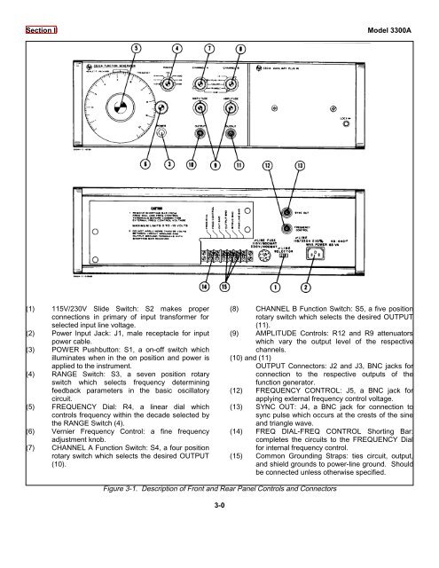
Section II Model 3300A<br />
(1) <strong>11</strong>5V/230V Slide Switch: S2 makes proper<br />
connections in primary of input transformer for<br />
selected input line voltage.<br />
(2) Power Input Jack: J1, male receptacle for input<br />
power cable.<br />
(3) POWER Pushbutton: S1, a on-off switch which<br />
illuminates when in the on position and power is<br />
applied to the instrument.<br />
(4) RANGE Switch: S3, a seven position rotary<br />
switch which selects frequency determining<br />
feedback parameters in the basic oscillatory<br />
circuit.<br />
(5) FREQUENCY Dial: R4, a linear dial which<br />
controls frequency within the decade selected by<br />
the RANGE Switch (4).<br />
(6) Vernier Frequency Control: a fine frequency<br />
adjus<strong>tm</strong>ent knob.<br />
(7) CHANNEL A Function Switch: S4, a four position<br />
rotary switch which selects the desired OUTPUT<br />
(10).<br />
(8) CHANNEL B Function Switch: S5, a five position<br />
rotary switch which selects the desired OUTPUT<br />
(<strong>11</strong>).<br />
(9) AMPLITUDE Controls: R12 and R9 attenuators<br />
which vary the output level of the respective<br />
channels.<br />
(10) and (<strong>11</strong>)<br />
OUTPUT Connectors: J2 and J3, BNC jacks for<br />
connection to the respective outputs of the<br />
function generator.<br />
(12) FREQUENCY CONTROL: J5, a BNC jack for<br />
applying external frequency control voltage.<br />
(13) SYNC OUT: J4, a BNC jack for connection to<br />
sync pulse which occurs at the crests of the sine<br />
and triangle wave.<br />
(14) FREQ DIAL-FREQ CONTROL Shorting Bar:<br />
completes the circuits to the FREQUENCY Dial<br />
for internal frequency control.<br />
(15) Common Grounding Straps: ties circuit, output,<br />
and shield grounds to power-line ground. Should<br />
be connected unless otherwise specified.<br />
Figure 3-1. Description of Front and Rear Panel Controls and Connectors<br />
3-0