Fractional E1 Access Units
Fractional E1 Access Units
Fractional E1 Access Units

You also want an ePaper? Increase the reach of your titles
YUMPU automatically turns print PDFs into web optimized ePapers that Google loves.
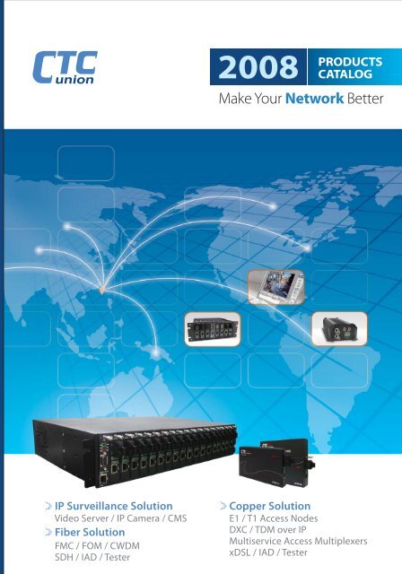
IP Surveillance Solution<br />
Video Server / IP Camera / CMS<br />
Fiber Solution<br />
FMC / FOM / CWDM<br />
SDH / IAD / Tester<br />
2008 PRODUCTS<br />
CATALOG<br />
Make Your Network Better<br />
Copper Solution<br />
<strong>E1</strong> / T1 <strong>Access</strong> Nodes<br />
DXC / TDM over IP<br />
Multiservice <strong>Access</strong> Multiplexers<br />
xDSL / IAD / Tester
WE CARE ABOUT<br />
CUSTOMER SATISFACTION!<br />
Make your network better.
Table of Contents 2008<br />
IP SURVEILLANCE<br />
Digital Video Server ..............................................................1-2<br />
IP Camera ...............................................................................1-5<br />
Central Management System .............................................1-7<br />
FIBER SERIES<br />
In-band Managed Series .................................................... 2-3<br />
Managed Series ................................................................. 2-12<br />
Unmanaged Series ............................................................ 2-22<br />
CWDM .................................................................................. 2-29<br />
FOM ....................................................................................... 2-33<br />
SDH ....................................................................................... 2-39<br />
Fiber Gateway ..................................................................... 2-41<br />
PDH SERIES<br />
CSU/DSU ............................................................................... 3-2<br />
DXC (Digital Cross Connect) .......................................... 3-11<br />
TDM over IP ......................................................................... 3-14<br />
Multiplexers ......................................................................... 3-15<br />
Inverse Multiplexer ............................................................. 3-25<br />
BROADBAND ACCESS - xDSL<br />
ADSL/ADSL2/2+ ................................................................... 4-2<br />
G.SHDSL/G.SHDSL.bis ....................................................... 4-9<br />
VDSL/VDSL2 ....................................................................... 4-19<br />
NETWORK TESTERS<br />
Protocol Analyzer ................................................................ 5-2<br />
BER Tester ............................................................................ 5-5<br />
PCM Analyzer ......................................................................... 5-7<br />
LAN Cable Tester ................................................................ 5-10<br />
INTERFACE CONVERTERS<br />
RS-232 Based Interface Powered Converter ................. 6-2<br />
V.35 Based Interface Powered Converter ....................... 6-4<br />
RS-232 Based Interface Converter .................................. 6-5<br />
V.35 Based Interface Converter ........................................ 6-8<br />
Short Haul Modem / Current Loop .................................... 6-9<br />
ACCESSORIES<br />
Fiber <strong>Access</strong>ories ................................................................. 7-2<br />
Cable <strong>Access</strong>ories ............................................................... 7-5<br />
Impedance Converter .......................................................... 7-6<br />
Surge Protector ..................................................................... 7-7<br />
MANAGEMENT<br />
EMS (Element Management System) ............................. 8-1<br />
GUI (Graphical User Interface) ......................................... 8-3
Table of Contents 2008<br />
1. IP SURVEILLANCE -<br />
Digital Video Server, IP Camera & Central Management<br />
System<br />
Digital Video Server<br />
4 channels H.264 video encoder server ........................................1-2<br />
DVS-8504E<br />
1/2/4 channels motion-JPEG video server ....................................1-3<br />
DVS-8201 ; DVS-8202 ; DVS-8204<br />
1 channel dual stream MPEG4 & motion-JPEG video server ........1-4<br />
DVS-8301<br />
IP Camera<br />
CMOS IP camera<br />
IPCAM-8309F<br />
Management Platform<br />
Central management system<br />
Smart-View Plus<br />
...........................................................................1-5<br />
..........................................................1-7<br />
2. FIBER SERIES -<br />
In-band Managed / Managed / Unmanaged Media Converter,<br />
CWDM, FOM, SDH, Fiber IAD<br />
In-Band Managed<br />
2U, 19”, 20-slot concentrator .......................................................... 2-3<br />
FRM220-CH20<br />
1-slot chassis ................................................................................. 2-4<br />
FRM220-CH01 (for FRM220 line card)<br />
In-band managed FE over fiber ..................................................... 2-5<br />
FRM220-10/100I<br />
802.3ah OAM managed FE over fiber .......................................... 2-6<br />
FRM220-10/100A<br />
802.3ah OAM managed GE over fiber .......................................... 2-7<br />
FRM220-1000EAS<br />
155Mbps fiber media converter and repeater ................................ 2-8<br />
FRM220-155MS<br />
In-band managed RS-485/RS-422/RS-232 over fiber ................... 2-9<br />
FRM220-Serial<br />
Voice (FXO/FXS) over fiber ......................................................... 2-10<br />
FRM220-FXO/FXS<br />
In-band managed FE over fiber, with PoE ................................... 2-11<br />
FMC-10/100I, FMC-10/100IP<br />
3U, 19“, 16-slot concentrator ....................................................... 2-12<br />
Managed<br />
FRM301<br />
FE over fiber media converter .................................................... 2-13<br />
FIB1-10/100F ; FIB2-10/100<br />
GE over fiber media converter .................................................... 2-14<br />
FIB1-1000ES ; FIB1-1000TS ; FIB1-1000DS ; FIB1-1000MG<br />
FIB1-1000TG ; FIB2-1000TG<br />
4U, 19”, 48-channel concentrator ............................................... 2-21<br />
FRM401<br />
TDM Solution<br />
<strong>E1</strong>/T1 over fiber ........................................................................... 2-17<br />
FIB1-<strong>E1</strong>/T1 ; FIB2-<strong>E1</strong>/T1<br />
V.35/X.21/RS-530/RS-449/RS-232 over fiber ............................. 2-18<br />
FIB1-Data ; FIB2-Data<br />
High-speed V.35/X.21/RS-530/RS-449/RS-232<br />
over fiber ..................................................................................... 2-18<br />
FIB1-Data/H<br />
Serial Solution<br />
RS-485/RS-422/RS-232 over fiber ................................................ 2-19<br />
FIB1-Serial ; FIB2-Serial<br />
RS-485/RS-422/RS-232 over fiber, with fiber daisy chain ............ 2-20<br />
FIB1-Serial/FDC<br />
Unmanaged<br />
1U, 10”(half 19”), 8-slot concentrator ........................................... 2-22<br />
FMC-CH08<br />
FE over fiber media converter ...................................................... 2-23<br />
FMC-10/100<br />
GE over fiber media converter ..................................................... 2-24<br />
FMC-1000E ; FMC-1000ES<br />
FE over fiber media converter, with PoE ...................................... 2-25<br />
FMC-10/100P<br />
FE over fiber media converter with PoF ............................................ 2-26<br />
FMC-10/100POF-S ; FMC-10/100POF-O<br />
Unmanaged Wall-mount Solution<br />
CO side fiber media concentrator & line card series .................... 2-27<br />
FRM402 ; FRM402-10/100 ; FRM402-1000 ; FRM402-Serial<br />
CPE side converter module with wall-mount kit ........................... 2-28<br />
FWM-K ; FWM-10/100 ; FWM-1000 ; FWM-Serial<br />
CWDM<br />
5U/2U, 19”, 19/6 slots CWDM concentrator ................................. 2-29<br />
SigmaLinks 5000 ; SigmaLinks 2000<br />
Line card for CWDM concentrator ................................................ 2-31<br />
Transponder ; mux/demux ; protection ; SNMP ; OADM<br />
FOM<br />
1U, 19”, 4-slot for modular interfaces(<strong>E1</strong>/T1/Datacom/Ethernet)<br />
FMUX01-A ; FMUX01-A +<br />
.. 2-33<br />
1U, 19”, with 4 <strong>E1</strong> or 4 T1 interfaces ........................................... 2-37<br />
FMUX04<br />
SDH<br />
Ethernet orTDM services over STM-1<br />
SDH155B ; SDH155A<br />
Fiber Gateway<br />
Fiber Based IAD with Wireless LAN<br />
GW421W<br />
3. PDH SERIES -<br />
CSU/DSU, DXC, TDM over IP, MSTP, Multiplexer, Inverse<br />
Multiplexer, Modular Interface<br />
CSU/DSU<br />
Unframed and <strong>Fractional</strong> <strong>E1</strong> <strong>Access</strong> <strong>Units</strong> ................................... 3-3<br />
G703<strong>E1</strong>-U / G703F<strong>E1</strong> /G703F<strong>E1</strong>-A ;<br />
ETU01 / ETU01-A / ETU01-D / ETU01-U<br />
10/100Base Ethernet over G.703 Unframed <strong>E1</strong> ........................... 3-8<br />
EOE-1<br />
<strong>Fractional</strong> <strong>E1</strong> Concentrator - Rack ............................................... 3-9<br />
ERM01<br />
DXC<br />
<strong>E1</strong> Digital Cross Connect in stand-alone type ........................... 3-11<br />
ETU/DXC<br />
<strong>E1</strong> Digital Cross Connect in rack type ...................................... 3-12<br />
ERM/DXC<br />
TDM over IP<br />
<strong>E1</strong> over IP Network<br />
IPM-1SE<br />
.......................................... 2-39<br />
............................................. 2-41<br />
..................................................................... 3-14
Conversion<br />
exTension<br />
C o m m u n i c a t i o n<br />
Multiplexer<br />
<strong>Fractional</strong> <strong>E1</strong>, 2 data ports, with sub <strong>E1</strong> ...................................... 3-15<br />
ETU01-C<br />
<strong>Fractional</strong> <strong>E1</strong> with modular interface, supports sub <strong>E1</strong> ................ 3-16<br />
ETU02-MUX / ETU02A-MUX<br />
Multi-service <strong>E1</strong> Time Division Multiplexer .................................. 3-18<br />
ETU02-MUX/PLUS / ERM-MUX/PLUS<br />
Inverse Multiplexer<br />
Ethernet over 4 <strong>E1</strong> in stand-alone type ........................................ 3-25<br />
ETU04A<br />
Ethernet over 4 <strong>E1</strong> in rack type .................................................... 3-26<br />
ERM04<br />
Interface Modules<br />
Ethernet router / bridge, datacom and voice interfaces<br />
4. BROADBAND ACCESS -<br />
ADSL2+, G.SHDSL / G.SHDSL.bis, VDSL / VDSL2<br />
ADSL - Splitter & Micro Filter<br />
For CO side ................................................................................... 4-2<br />
ALS-R50 ; ALS-R60<br />
For CPE side ................................................................................. 4-4<br />
MDF type ...................................................................................... 4-4<br />
ALS-P10<br />
POTS splitter and micro filter ........................................................ 4-5<br />
ALS-12 ; ALS-M12, ALS-10/IT ; ALS-10/UK<br />
ALS-10/FI ; ALS-10/FA<br />
POTS splitter over ISDN ............................................................... 4-7<br />
ALS-10-EU/I<br />
ADSL - Modem<br />
ADSL2/ADSL2+ bridge, router modem<br />
ATU-R150<br />
G.SHDSL TDM<br />
TDM based concentrator .............................................................. 4-9<br />
SHRM03-<strong>E1</strong> ; SHRM03-V35 ; SHRM03-ET100<br />
TDM based <strong>E1</strong>/V.35/LAN I/F modem .......................................... 4-11<br />
SHDTU03-<strong>E1</strong> ; SHDTU03-V35 ; SHDTU03-ET100<br />
G.SHDSL.bis TDM based multiple interface modem .................. 4-14<br />
SHDTU03b-NTU<br />
G.SHDSL ATM<br />
ATM based concentrator ............................................................. 4-15<br />
SHRM03-ET100R<br />
ATM based 2/4-wire router .......................................................... 4-16<br />
SHDTU03-ET10R ; SHDTU03-ET10RS ;<br />
SHDTU03A-ET10R ; SHDTU03A-ET10RS ;<br />
SHDTU03AF-ET10R ; SHDTU03AF-ET10RS ;<br />
G.SHDSL.bis ATM based 2/4-wire router .................................... 4-17<br />
SHDTU03bF-ET10R ; SHDTU03bF-ET10RS<br />
SHDTU03bAF-ET10RS<br />
VDSL2 - Modem<br />
VDSL2 CO/CPE Modem<br />
V2MC<br />
............... 3-27<br />
......................................... 4-8<br />
............................................................. 4-19<br />
5. MEASUREMENT<br />
Protocol Analyzer<br />
HCT-7000 .................................................................................... 5-2<br />
HCT-6000/6000A ......................................................................... 5-4<br />
BER Tester<br />
HCT-BERT/H ............................................................................... 5-5<br />
HCT-BERT/C ............................................................................... 5-6<br />
PCM Analyzer<br />
BTM10-<strong>E1</strong>/T1 (a, b, c)<br />
LAN Cable Tester<br />
LCT-300/400 .............................................................................. 5-10<br />
6. INTERFACE CONVERTER<br />
RS-232 Based Interface Powered<br />
V.35IP/449IP/X.21IP ...................................................................... 6-2<br />
V.35Ip-CAB ................................................................................... 6-3<br />
V.35 Based Interface Powered<br />
V.35/530IP, V.35/449IP, V.35/X.21IP ............................................. 6-4<br />
RS-232 Based<br />
IC485-3 ....................................................................................... 6-5<br />
IC232 TTL ................................................................................... 6-6<br />
IC485IP-1M/F, IC485IP-2 ............................................................ 6-7<br />
V.35 Based<br />
V.35/485-1<br />
Short Haul Modem<br />
IC232IP-SM/F, IC232IP-2M/F<br />
Current Loop<br />
ICCL-2M/F .................................................................................. 6-10<br />
7. ACCESSORIES<br />
Fiber <strong>Access</strong>ories<br />
Fiber Optic Patch Cord/Pigtail ...................................................... 7-2<br />
Fiber Attenuator ............................................................................ 7-2<br />
GBIC/SFP Transceiver ................................................................ 7-3<br />
Cable <strong>Access</strong>ories<br />
Adaptor & Gender Changer<br />
/Communication Network Cable.<br />
Impedance Converter<br />
Balun-P/B1/B2 ............................................................................. 7-6<br />
G.703 mini Balun BLN3010 ; BLN4010 ....................................... 7-6<br />
Surge Protector<br />
<strong>E1</strong> / Ethernet Surge Protector<br />
SP-SE-R01-8/R08-8 ; SP-RE-R16-8/R24-8 ................................. 7-7<br />
SP-SE-B01 ................................................................................... 7-8<br />
Telephone Surge Protector<br />
TSP-10 ......................................................................................... 7-8<br />
8. MANAGEMENT<br />
................................................................. 5-7<br />
.................................................................................... 6-8<br />
....................................................... 6-9<br />
.................................................. 7-5<br />
Element Management System<br />
EMS .............................................................................................. 8-1<br />
Graphical User Interface<br />
FRM301/401 GUI ......................................................................... 8-3
A More Intelligent Network<br />
In-band Managed Fiber Media Concentrator<br />
NON-Intrusive on fiber transmission<br />
Provides the most comprehensive platform for various I/F<br />
Triple (Quadruple) Play<br />
Meets Rising Demands For Upstream Network Bandwidth<br />
8-slot Chassis Concentrator<br />
Capable of holding any FMC series<br />
media converters.<br />
(FE/GE/POF/VDSL2, etc)<br />
New<br />
FE<br />
GE<br />
TDM<br />
FXO/FXS<br />
Datacom<br />
STM-1/OC-3<br />
Please See Page 2-2<br />
New<br />
Extremely cost effective,<br />
non-managed solution<br />
for fiber and copper media<br />
conversion<br />
Products<br />
Products<br />
Please See Page 2-22 & 4-19
IP Surveillance Series<br />
DVS, IP Camera, CMS, the Comprehensive System<br />
* H.264/MPEG4/MJPEG Digital Video Server<br />
* MPEG4/MJPEG CMOS IP Camera<br />
BEST Solution in xDSL<br />
G.SHDSL.bis (up to 11.4Mbps, 4-wire, via copper)<br />
2-wire/4-wire Router with<br />
4-port Switching Hub<br />
(Firewall optional)<br />
Advanced Fiber Optical Multiplexer<br />
Built-in 100M Ethernet Trunk Bandwidth<br />
155Mbps bandwidth in optical trunk & built-in<br />
10/100 Ethernet make PDH network more efficient<br />
and flexible to assign to 4 <strong>E1</strong>/T1, 4 FXO/FXS,<br />
Datacom, and FE I/F (max. 16-ch).<br />
* CMS Platform up to thousands camera<br />
Please See Page 1-1<br />
<strong>E1</strong>/V.35/Ethernet<br />
Multi-Interface NTU Modem<br />
* Redundancy for power and fiber link.<br />
* Standard SNMP and EMS for management.<br />
* Modular and hot-swappable design for easier installation and interface change.<br />
New<br />
New<br />
Please See Page 4-14&17<br />
New<br />
Products<br />
Products<br />
Products<br />
Please See Page 2-35
1-1<br />
1. IP Surveillance<br />
IP Surveillance Family<br />
Embedded Type Product Name Description Type Page<br />
Digital Video Server DVS-8504E 4-channel H.264 Encoder Video Server S 1-2<br />
Digital Video Server DVS-8201 1-channel Motion-JPEG Digital Video Server S 1-3<br />
Digital Video Server DVS-8202 2-channel Motion-JPEG Digital Video Server S 1-3<br />
Digital Video Server DVS-8204 4-channel Motion-JPEG Digital Video Server S 1-3<br />
Digital Video Server DVS-8301 1-channel Motion-JPEG & MPEG4 Digital<br />
Video Server<br />
S 1-4<br />
IP Camera IPCAM-8309F Dual Stream CMOS IP Camera with Intelligent<br />
Motion Detection<br />
S 1-5<br />
Central Management System Smart-View Plus The Comprehensive Surveillance System for<br />
Enterprise<br />
S 1-7<br />
S= Standalone
Digital Video Server<br />
Digital Video Server<br />
DVS-8504E<br />
H.264 Encoder Video Server<br />
Features<br />
Complies with H.264 compression technology<br />
Provides high quality analog video and audio<br />
Sequence mode for multiple video sources<br />
Built-in Web server for easy management<br />
Supports secure management and encrypted video streams<br />
Specifications<br />
Application<br />
Motion Detection<br />
Storage<br />
Video Rotate<br />
Configuration Backup/Recovery<br />
Firmware Update<br />
NTP<br />
Video Adjustment<br />
Live View Mode<br />
User Group<br />
FTP Client<br />
Alarm notice<br />
Alarm Sending<br />
Alarm Sending Path<br />
Live Video Digital Zoom<br />
Video Snapshot<br />
SMTP<br />
SMTP Authentication<br />
Alarm Buffer<br />
Event Define<br />
Text Overlay<br />
Privacy Mask<br />
Language<br />
Log<br />
Environment<br />
Operating Temperature<br />
Storage Temperature<br />
Humidity<br />
Input Power<br />
Reset<br />
Certification<br />
LED Indicators<br />
4 Detection Windows、20 Level Sensitive、Drag and Drop<br />
Configurable Detection Windows<br />
Support NAS、NVR<br />
Mirror、Reverse<br />
Web Browser<br />
Web Browser、TFTP<br />
Sync with PC、Sync with NTP Server、Manual<br />
Brightness、Contract、Saturation、Color tone level<br />
1X,2X,Full Screen<br />
Admin、Operator、Viewer<br />
Server Name、Username、Password<br />
FTP、E-Mail、DO1、DO2、SMS<br />
Image File、Date、Time<br />
FTP、E-Mail<br />
Adjustable 4X Digital Zoom<br />
Live View Mode<br />
SMTP Server Name<br />
POP Server Name、Username、Password<br />
Pre Alarm period 1 min、Post Alarm period 1 min(Recording in Hard<br />
Disk)<br />
User Define Video Frame Rate and Video Resolution and Video<br />
Quality When Alarm Input and Motion Detection<br />
Configurable Text Color、Background Color、Date/Time、Display<br />
Position<br />
Support 4 Privacy Mask Windows<br />
English、Simplified Chinese、Traditional Chinese<br />
System Log、Operating Log<br />
0 to 70 Degree Celsius<br />
-30 to 85 Degree Celsius<br />
0%~95% (non-condensing)<br />
12V DC、1A<br />
Reset Button(Factory Default)<br />
FCC Part 15 class A、CE、UL1950、CCC<br />
Power、LAN、Video Status<br />
Specifications<br />
Image Compression<br />
Video Compression<br />
Video Resolution<br />
Video Streaming<br />
Operating System<br />
Frame<br />
Bit Rate<br />
Frame Rate<br />
Video Quality<br />
Video Interface<br />
Input Channel<br />
Video Format<br />
Signal<br />
Connector<br />
Output Channel<br />
Audio Interface<br />
Input Channel<br />
Output Channel<br />
Audio Compression<br />
Application<br />
Input/Output Signal<br />
Input/output impendence<br />
Data Interface<br />
PCMCIA<br />
GPIO Interface<br />
PTZ Protocol<br />
PTZ Baud Rate<br />
PTZ Control Speed<br />
PTZ Preset<br />
PTZ Patrol<br />
Console Interface<br />
Management<br />
Order Information<br />
DVS-8504E<br />
H.264(CBR/VBR)<br />
4CIF 704x480(NTSC)/704x576(PAL)<br />
2CIF 704x240(NTSC)/704x288(PAL)<br />
CIF 352x240(NTSC)/352x288(PAL)<br />
QCIF 176x120(NTSC)/176x144(PAL)<br />
Master Stream、Slave Stream(Master Stream to select 4CIF,Slave<br />
Stream only to select CIF or QCIF)<br />
Embedded LINUX<br />
4CH D1 120 (NTSC) / 100 (PAL) fps<br />
64K/128K/384K/512K/768K/1024K/1.5M/2M<br />
1/16、1/8、1/4、1/2、1、2、3、5、8、10、15、20、25、30<br />
5 Level(Medium、Standard、Good、Detailed、Excellent)、Auto<br />
4 Channels<br />
NTSC/PAL Configurable<br />
1V p-p、75 ohm<br />
4 BNC<br />
1 Channel(Quad Mode)<br />
4CH Mono Audio(RCA)<br />
1CH Mono Audio(RCA)<br />
ADPCM G.726、G.711<br />
Two-way Audio<br />
6V p-p、+10dBm max<br />
600 ohm<br />
PCMCIA*1(support WiFi、3G card)<br />
RS-485/RS-232(DB9 Interface)、4*Alarm Input、2*Alarm Output<br />
Support Pelco D、Pelco P<br />
2400、4800、9600、12800、19200 kbps<br />
Pan、Tilt、Zoom、Focus、Iris<br />
32 Preset Position<br />
4 Tour Mode (Each Mode have 10 Position)<br />
RS-232<br />
Telnet、Console、Web (CGI)、SNMP v1/v2c<br />
4 CH H.264 Encoder Video Server<br />
1<br />
IP Surveillance<br />
Fiber Series PDH Series Broadband <strong>Access</strong> Measurement<br />
Interface<br />
Converter<br />
Datacom<br />
<strong>Access</strong>ories<br />
Network<br />
Management<br />
1-2
1-3<br />
Digital Video Server<br />
Digital Video Server<br />
DVS-8201/8202/8204<br />
Motion-JPEG Networking Digital Video Server<br />
DVS-8201/8202/8204 Networking Video Server is an network-based digital video server,<br />
capable of connecting one/two/four channels of video sources to distribute their<br />
compressed live video into Intranet-Internet through Internet Explorer connection.<br />
DVS-8201/8202/8204 is a self-contained Web Server, so users could access the camera<br />
just browsing website over Internet using standard browser such as Internet Explorer or<br />
Netscape, and do all the management, configuration, and monitoring easily.<br />
Features Specifications<br />
Self-Contained HTTP Web Server providing Internet capability<br />
IP assignment via ARP/Web Page/IP, easy to install for users.<br />
JAVA-based web page providing maximum platform compatibility<br />
Active-X control for Internet Explorer providing maximum<br />
performance.<br />
Motion Detection / Date / Time / GPIO Input for event trigger<br />
Email / FTP / Relay Out for event action<br />
Programmable event script for various applications.<br />
DDNS support for dynamic IP application<br />
Remote Upgradeable firmware and user content pages via FTP<br />
Server operating control through CGI base script easy for users to<br />
integrate the application for users.<br />
Standard BNC connectors, automatic video standard (NTSC/PAL)<br />
detection.<br />
Green power, fan less, hardware watchdog providing robustness<br />
system in critical environment<br />
Ordering Informations<br />
DVS-8201 One Channel Motion-JPEG Network Video Server<br />
DVS-8202 Two Channels Motion-JPEG Network Video Server<br />
DVS-8204 Four Channels Motion-JPEG Network Video Server<br />
DVS-8201/8202/8204 contains image compression chipset that is capable of delivering<br />
standard JPEG, MJPEG, and real-time video into limited network bandwidth.<br />
DVS-8201 One Channel<br />
DVS-8202 Two Channels<br />
DVS-8204 Four Channels<br />
Video Format NTSC, PAL configurable<br />
Video Compression JPEG, Motion-JPEG<br />
NTSC: 704*480(single), 352*240(quad)<br />
PAL: 704*576(single), 352*288(quad)<br />
Video through-put: Up to 30 frame per<br />
second<br />
Network through-put: Max. up to 800K<br />
Bytes pre second<br />
Signal 1.0 VP-P<br />
Impedance 75 ohms<br />
Video Adjustment Brightness, contrast, hue, saturation,<br />
quality level<br />
Interface Connector 8201:BNC*1, 8202:BNC*2, 8204:BNC*4<br />
Camera Control Pan/Tilt/Zoom supported via serial port<br />
(RS-485)<br />
CPU 32 Bits RISC Processor<br />
ROM 2M Bytes FlashROM<br />
RAM 16M Bytes SDRAM<br />
WatchDog Chip to monitor out tolerance system<br />
voltage and abnormal program execution<br />
Two RS-232 Serial One for external modem, one for PTZ<br />
Port<br />
control<br />
Ethernet Connection RJ-45 for 10/100Mbps Ethernet connection<br />
LED Indications Network and power/system status<br />
User Programable Event script and wizard supported<br />
Trigger Time(frequency)/GPIO input/Motion<br />
Store image to internal buffer<br />
FTP image to remote side<br />
E-mail image to specify account<br />
Relay out to control external devices<br />
Assign IP address Using ARP/via RS-232/IP installer<br />
System Windows 2000 SP4 or Windows<br />
Browser Internet Explorer 6.0<br />
Software DirectorX 9.0C<br />
Dimension 243*44.5*153mm (W*D*H)<br />
Power DC 12V, 1A or DC 10~24V, 1A<br />
Power Consumption 7W<br />
Temperature 5~50oC (Operating) ; 0~70o Video Interface<br />
Input Channel<br />
Video Resolution<br />
Video Performance<br />
Hardware<br />
GPIO<br />
Event Trigger & Action<br />
Fully opto-isolated four alarm input and<br />
one relay output<br />
Action<br />
Installation<br />
System Requirements<br />
General<br />
C (Storage)<br />
Humidity 0~95%
Digital Video Server<br />
Features<br />
Digital Video Server<br />
DVS-8301<br />
Dual Stream Networking Digital Video<br />
Server(MPEG4 & Motion-JPEG)<br />
PoE (Power over Ethernet) built-in<br />
Simultaneous Motion-JPEG & MPEG-4 Dual Streaming<br />
Excellent image quality with up to 30 fps in Full D1 resolution<br />
Supports two-way audio<br />
Digital I/O for external alarm or sensor<br />
Supports 3GPP/ISMA RTSP<br />
Supports multiple PTZ camera control protocols through RS485<br />
Intelligent motion detection<br />
UPnP for fast and easy installation<br />
Bundled 16 channel surveillance software<br />
Specifications<br />
Network Interface<br />
10/100Base-T Ethernet<br />
Protocol TCP/IP, DHCP, PPPoE, ARP, ICMP, FTP, SMTP, DNS,<br />
NTP, IGMP, UPnP, RTSP, RTP, HTTP, TCP, UDP,<br />
3GPP/ISMA RTSP<br />
Installation<br />
Using CTCU IP installer (Win32 Application)<br />
Protocol<br />
Remote upgarde via FTP,<br />
Customized Web UI is upgradeable via FTP and Telnet<br />
Security<br />
Multi-tier access control for configuration<br />
Recording<br />
Directly from web UI while viewing the live video stream, 16<br />
channel free recording sofware<br />
Dimension<br />
129*98*51.6mm (W*D*H)<br />
Approvals<br />
CE, FCC<br />
Operating Temp.<br />
0~50 o C (Operating) ; 0~70 o Network Environment<br />
Management<br />
General Specification<br />
C (Storage)<br />
Operating Humidity<br />
20~80% RHG<br />
Input Voltage<br />
DC 12V, 1A<br />
Power Consumption<br />
Min: 0.44W ; Max: 12.95W<br />
Package Contents<br />
Content<br />
CD Title with manuals and S/W, Quick installation guide,<br />
One Ethernet cable, Power adapter, One mini-<br />
DIN/Terminal Block Conversion Cable(Optional)<br />
Specifications<br />
Video Interface<br />
Input Channel<br />
One Channel<br />
Video Format<br />
NTSC, PAL<br />
Video Compression<br />
MPEG4 Simple Profile, Motion-JPEG<br />
Video Resolution<br />
Full D1 (4CIF): NTSC=702*480, PAL=702*576,<br />
NTSC=352*240, PAL=352*288,<br />
NTSC=176*120, PAL=176*144<br />
Video Bit Rate<br />
16K ~2M bits/sec<br />
Video Adjustment<br />
Brightness, Contrast, Hue, Saturation, Frame rate, Bit rate,<br />
Constant Bit Rate (CBR), Variable Bit Rate (VBR)<br />
Camera Control<br />
Pan/Tilt/Zoom supported via serial port (RS-485),<br />
support 32 preset position, support 4 patrol function<br />
Hardware<br />
System<br />
CPU: 32 Bits RISC Processor, ROM: 8M Bytes FlashROM<br />
RAM: 64MB SDRAM, Embedded OS : Linux<br />
LED Indications<br />
Network and power status<br />
Connector<br />
Ethernet<br />
One RJ-45 (supports Power-over-Ethernet)<br />
One mini-DIN<br />
For RS-485/GPIO<br />
Audio In<br />
One 3.5mm jack (supports two-ways audio ADPCM 64Kbps)<br />
Audio Out<br />
One 3.5mm jack (supports two-ways audio ADPCM 64Kbps)<br />
BNC<br />
One BNC video input, and one BNC loopback video output<br />
GPIO<br />
Fully opto-isolated one alarm input and one relay output<br />
Event Trigger & Action<br />
Trigger<br />
GPIO input/Motion detection<br />
Action<br />
Pre and post alarm buffer<br />
Order Information<br />
DVS-8301<br />
FTP image to remote side<br />
E-mail image to specify account<br />
Relay out to control external devices<br />
One Channel Dual Stream Network Digital Video<br />
Server(MPEG4 & Motion-JPEG)<br />
1<br />
IP Surveillance<br />
Fiber Series PDH Series Broadband <strong>Access</strong> Measurement<br />
Interface<br />
Converter<br />
Datacom<br />
<strong>Access</strong>ories<br />
Network<br />
Management<br />
1-4
1-5<br />
IP Camera<br />
Features<br />
IP Camera<br />
IPCAM8309F<br />
Dual Stream CMOS IP Camera<br />
Simultaneous Motion JPEG and MPEG-4<br />
Excellent Image Quality with up to 30 fps in all resolutions<br />
Superior Low-light Performance with Automatic Night-mode<br />
Two-way Audio with Built-in Microphone<br />
Optimal synchronization of Audio and Video<br />
Support 3GPP/ISMA (RSTP)<br />
UPnP for fast and easy Installation<br />
Intelligent Motion Detection<br />
Bundled 16 Channel Surveillance Software<br />
Application<br />
Specifications<br />
Image Sensor<br />
1/4" Progressive CMOS Sensor<br />
Zoom<br />
10 X Digital<br />
Video Compression<br />
MPEG4 Part-2, Motion JPEG<br />
Video Max Resolution<br />
640 x 480 (VGA)<br />
Minimum Illumination<br />
1 Lux at F2.0<br />
Frame Rate<br />
Motion JPEG: Up to 30 fps in all resolutions<br />
MPEG-4: Up to 30 fps in all resolutions<br />
Video Stream<br />
Simultaneous Motion JPEG and MPEG-4<br />
Controllable frame rate and bandwidth<br />
3GPP/ISMA RTSP compatible<br />
Audio<br />
Two-way (full duplex) ; Built-in microphone<br />
Operation System<br />
Linux 2.4<br />
System Requirement<br />
Pentium III CPU 500 MHz or higher, or equivalent AMD<br />
128MB RAM Windows 98, ME, 2000, XP, Vista Internet<br />
Explorer 6 or later<br />
Processors and<br />
Memory ARM9 based 32-bit RISC CPU 32MB RAM, 4MB Flash<br />
Ethernet<br />
One RJ-45<br />
Audio Out<br />
One 3.5mm jack<br />
Detection<br />
Built-in multi-window motion detection image upload over<br />
FTP, e-mail<br />
Notification<br />
HTTP notification over TCP and e-mail<br />
Network Interface<br />
IEEE 802.3 10/100Base-T Ethernet<br />
Supported Protocols HTTP, TCP/IP, SNMP, 3GPP/ISMA RTSP, SMTP, FTP,<br />
ICMP, IGMP, DHCP, UPnP, ARP, DNS, DynDNS, PPPoE,<br />
NTP<br />
Software<br />
Professional surveillance application for viewing, recording<br />
and archiving up to 16 channel<br />
Dimension<br />
98*58*31mm (W*D*H)<br />
Approvals<br />
CE, FCC, RoHS<br />
Operating Temp.<br />
0~45 o C (32 - 113 o Video & Audio Interface<br />
Hardware<br />
Connector<br />
Alarm & Event Management<br />
Network Environment<br />
Video Surveillance Software<br />
General Specification<br />
F)<br />
Operating Humidity<br />
20~80% RHG<br />
Input Voltage<br />
DC 5V, 1.2A<br />
Order Information<br />
IPCAM8309F<br />
Dual Stream CMOS IP Camera
All You Can Watch<br />
and Do From<br />
CMS<br />
Sewage<br />
Disposal<br />
Central Warehouse<br />
Office<br />
Security<br />
Security Humidity<br />
Temp.<br />
Sensor<br />
Sensor<br />
Entrance<br />
Guard<br />
Fire<br />
Alarm<br />
Entrance<br />
Video Vi Vid V deo<br />
Monitor<br />
RFID<br />
Power<br />
Plant<br />
Security<br />
Traffic<br />
Monitor<br />
Power<br />
Plant<br />
Security<br />
Dam<br />
Security<br />
DI<br />
DO<br />
Wide Scalability, Remote <strong>Access</strong>ibility, Distributed Architecture<br />
Find Your IP Surveillance Solution @ CTC Union<br />
1<br />
IP Surveillance<br />
Fiber Series PDH Series Broadband <strong>Access</strong> Measurement<br />
Interface<br />
Converter<br />
Datacom<br />
<strong>Access</strong>ories<br />
Network<br />
Management<br />
1-6
All-in-One Surveilance Solution<br />
CTC Union Smart-View Plus and a versatile API/SDK provides you endless integration possibilities with video monitoring, access control, POS<br />
systems, alarms, gate barriers, etc.<br />
Enterprise-Level Surveillance Management<br />
Smart-View Plus provides the architectural and distribution management distributed process with centralized capabilities. With the system's cascaded<br />
management technology, the headquarters can manage the whole system, track all surveillance events and monitor the critical video while<br />
the remote stations can monitor their own.<br />
Scalabilities<br />
Support for multiple servers, sites and clients allows you to<br />
extend the systems to fit your organization.<br />
Compatibility<br />
Compatible with multiple venders' IP cameras and digital video<br />
servers with MJPG (Motion-JPEG) and MPEG4.<br />
Automatic Alert<br />
Major/minor events alert through e-mail or instant messages to<br />
authorized administrators.<br />
Flexible Storage Capability<br />
In-unit storage as well as centralized storage are available to<br />
enhance resiliency to network failure and improve disaster<br />
recovery capability.
Input Device<br />
IP Camera Axis 205/2100/2120/2130,<br />
D-Link:<br />
2000/2100+/2100/2100G/5300<br />
5300W/5300G/900/900W<br />
Panasonic: KX-HCM130/KX-HCM180<br />
Pixord:120/200/205/240/241<br />
Vivotek:<br />
PT2111/3112/3114/PZ6112/IP3111<br />
Dome Camera Dynacolor D7720 Sony D30/D31<br />
Lilin PIH-7XNFIP Series<br />
Pelco D/P series<br />
I/O Controller Atop GW-26A<br />
<strong>Access</strong> Controller Atop GW-26A, Poris Series<br />
Video Server Axis:2400/2401/241S<br />
CTC Union: DVS-8201/02/04,<br />
DVS-8301<br />
Vivotek: 2402/VS3102<br />
Application Programming Interface<br />
(APIs) are available for device<br />
integration<br />
Video<br />
Input Source QCIF, CIF, 4CIF ; Record: CIF, 4CIF<br />
Playback: CIF, 4CIF ; Export: AVI<br />
Event Management<br />
Input Soruce I/O devices (sensor input), video<br />
motion detection, access control<br />
events (normal open, invaild card,<br />
incorrect password, and invalid time<br />
segment)<br />
Trigger Actions I/O devices (relay output, disable<br />
sensor input), video recording, send<br />
e-mail, send SMS to mobile phone,<br />
control PTZ camera to present<br />
postion, pop-up video on Smart-View<br />
Plus Client.<br />
Model<br />
SVP-P<br />
SVP-O<br />
Description<br />
Smart-View Plus Platform with 32<br />
nodes (can support thousands links)<br />
*Efficient links in smart-view plus<br />
depend on server level and bandwidth<br />
flow<br />
Smart-View Plus Option, with 4 Links<br />
add-on package
Network Type Model Name<br />
Fiber Series<br />
Description Type Page<br />
Managed Fiber Media Converter Series<br />
In-band Managed Chassis FRM220-CH20 2U 19”, 20 slots In-band Managed Chassis R, M 2-3<br />
Stand-alone Chassis FRM220-CH01 CPE stand-alone one slot chassis S 2-4<br />
Fast Ethernet FRM220-10/100I 10/100Base-TX to 100Base-FX w/ In-band L, S, M 2-5<br />
Fast Ethernet FRM220-10/100A 10/100Base-TX to 100Base-FX w/ In-band 802.3 OAM L, S, M 2-6<br />
Gigabit Ethernet FRM220-1000EAS 2-port 10/100/1000Base-TX to 2-port 1000Base-FX L, S, M 2-7<br />
Fast Ethernet, STM-1 FRM220-155MS 155M dual fiber media repeater (MM to SM) L, S, M 2-8<br />
RS-422/485/232 FRM220-Serial (RS422/485/232) Terminal Block to MM or SM L, S, M 2-9<br />
POTS 2-wire FRM220-FXO/FXS Twisted pair to MM or MS L, S, M 2-10<br />
Fast Ethernet FMC-10/100I 10/100Base-TX to 100Base-FX w/ In-band S, M 2-11<br />
Power over Ethernet FMC-10/100IP 10/100Base-TX to 100Base-FX w/ In-band S, M 2-11<br />
Managed Chassis FRM301 3U, 19”, 16 slots SNMP managed chassis R, M 2-12<br />
Fast Ethernet FIB1-10/100F 10/100Base-TX to 100Base-FX MM or SM L, S, M 2-13<br />
Fast Ethernet<br />
(With Built-in Power)<br />
FIB2-10/100F 10/100Base-TX to 100Base-FX MM or SM S, M 2-13<br />
Gigabit Ethernet FIB1-1000ES 10/100/1000Base-TX to 1000Base-FX SFP MM or SM L, S, M 2-14<br />
Gigabit Ethernet FIB1-1000TS 1000Base-TX to 1000Base-FX SFP MM or SM L, S, M 2-15<br />
Gigabit Ethernet FIB1-1000TG 1000Base-TX to 1000Base-FX GBIC MM or SM L, S, M 2-15<br />
Gigabit Ethernet<br />
(With Built-in Power)<br />
FIB2-1000TG 1000Base-TX to 1000Base-FX GBIC MM or SM S, M 2-15<br />
Gigabit Ethernet FIB1-1000DS 1.25G Dual SFP media repeater (MM to SM) L, S, M 2-16<br />
Gigabit Ethernet FIB1-1000MG 1000Base-SX to 1000Base-LX GBIC (MM to SM) L, S, M 2-16<br />
<strong>E1</strong>/T1 FIB1-<strong>E1</strong>/T1 BNC or RJ45 to MM or SM L, S, M 2-17<br />
<strong>E1</strong>/T1<br />
(With Built-in Power)<br />
FIB2-<strong>E1</strong>/T1 BNC or RJ45 to MM or SM S, M 2-17<br />
V.35/X.21/RS-530/449 FIB1-DATA 2M (V35/X.21/RS530/449/232) 26-pin to MM or SM L, S, M 2-18<br />
V35/X.21/RS530/449<br />
(With Built-in Power)<br />
V.35/X.21/RS-530/449<br />
(With High Speed)<br />
FIB2-DATA 2M (V35/X.21/RS530/449/232) 26-pin to MM or SM S, M 2-18<br />
FIB1-DATA/H 8M (V35/X.21/RS530/449) 26-pin to MM or SM S, M 2-18<br />
RS-485/422/232 FIB1-Serial (RS485/422/232) terminal block to MM or SM L, S, M 2-19<br />
RS-485/422/232<br />
(With Built-in Power)<br />
RS-485/422/232<br />
(With Fiber Ring)<br />
FIB2-Serial (RS485/422/232) terminal block to MM or SM S, M 2-19<br />
FIB1-Serial/FDC (RS485/422/232) terminal block to dual fiber MM or SM S, M 2-20<br />
Managed Chassis FRM401 4U, 19”, 12 slots managed chassis R, M 2-21<br />
Fast Ethernet FRM401-10/100 4ch 10/100Base-TX to 100Base-FX MM or SM L, S, M 2-21<br />
Unmanaged Fiber Media Converter Series<br />
Unmanaged Chassis FMC-CH08 2U, 10”, 8 slots unmanaged chassis R 2-22<br />
Fast Ethernet FMC-10/100 10/100Base-TX to 100Base-FX MM or SM S 2-23<br />
Gigabit Ethernet FMC-1000E 10/100/1000Base-TX to 1000Base-FX MM or SM S 2-24<br />
Gigabit Ethernet FMC-1000ES 10/100/1000Base-TX to 1000Base-FX SFP MM or SM S 2-24<br />
Power over Ethernet FMC-10/100P 10/100Base-TX to 100Base-FX MM or SM (PoE) S 2-25<br />
Plastic over Fiber FMC-10/100POF-S 10/100Base-TX to 100Base-FX MM or SM POF SMI S 2-26<br />
Plastic over Fiber FMC-10/100POF-O 10/100Base-TX to 100Base-FX MM or SM POF S 2-26<br />
2-1<br />
2. Fiber Series<br />
R = Rack, L = Line card, S = Stand-alone, M = Management
2. Fiber Series<br />
Network Type Model Name<br />
Fiber Series<br />
Description Type Page<br />
Wall Mount Umanaged Fiber Converter Series<br />
Unmanaged Chassis FRM402 4U, 19”, 16 slots managed chassis R 2-27<br />
Fast Ethernet FRM402-10/100 4ch 10/100Base-TX to 100Base-FX MM or SM L 2-27<br />
Gigabit Ethernet FRM402-1000 2ch 1000Base-TX to 1000Base-FX MM or SM L 2-27<br />
RS485/422/232 FRM402-Serial (RS485/422/232) DB9 to MM or SM L 2-27<br />
Fast Ethernet FWM-10/100 10/100Base-TX to 100Base-FX MM or SM S 2-28<br />
Gigabit Ethernet FWM-1000 1000Base-TX to 1000Base-FX MM or SM S 2-28<br />
RS485/422/232 FWM-Serial (RS485/422/232) DB9 to MM or SM S 2-28<br />
CWDM<br />
CWDM SML-50-9051 5U, 19”, 17 slots chassis R, M 2-29<br />
CWDM SML-20-9021 2U, 19”, 6 slots chassis R, M 2-30<br />
CWDM SML-50-8012 1.25G 2 channels transponder L, S, M 2-31<br />
CWDM SML-50-8022 2.5G 2 channels transponder L, S, M 2-31<br />
CWDM SML-50-81XX (4) or (8) Channels MUX/DEMUX L, S, M 2-31<br />
CWDM SML-50-8210 Fiber optic protection switch L, S, M 2-32<br />
CWDM<br />
FOM<br />
SML-50-83XX (1) or (2) channels drop/insert OADM L, S, M 2-32<br />
Fiber Multiplexer FMUX01A <strong>E1</strong>/T1/Datacom/Ethernet fiber optic multiplexer R, M 2-33<br />
Fiber Multiplexer FMUX01A+ <strong>E1</strong>/T1/Voice/Datacom fiber optic multiplexer R, M 2-35<br />
Fiber Multiplexer<br />
SDH<br />
FMUX04 4-port <strong>E1</strong> or T1 fiber optic multiplexer S, M 2-37<br />
STM1 SDH155B Stand-alone Ethernet and TDM over STM1 S, M 2-39<br />
STM1<br />
IAD<br />
SDH155A Rack type Ethernet and TDM over STM1 R, M 2-40<br />
Fiber IAD GW421W Single mode, single fiber wireless VoIP IAD S, M 2-41<br />
Management<br />
Card<br />
Thermal Holes<br />
AC power module<br />
Ethernet 10/100<br />
In-band line card<br />
STM-1 MM to SM<br />
line card with SFP<br />
DC power module<br />
STM-1 MM to<br />
SM line card<br />
R = Rack, L = Line card, S = Stand-alone, M = Management<br />
Expansion Chassis<br />
Connection<br />
Datacom Serial line<br />
card with SFP<br />
Alarm<br />
Relays<br />
Connection<br />
Hot swappable cooling fan.<br />
Datacom Serial<br />
line card<br />
Rack Mount Panel<br />
Voice (FXO/FXS)<br />
line card<br />
2-2
2-3<br />
Fiber Media Converter<br />
Features<br />
In-band Managed Platform<br />
FRM220-CH20<br />
In-band Managed 20 Slots Media<br />
Converter Center<br />
The FRM220-CH20 is a 2U high 19" Rack, 20 slot modular media converter center. The<br />
FRM220 provides an economic solution in high density Fiber Converter installations in<br />
enterprises or central offices. The Power Modules are designed for redundant power<br />
supply operation. All critical components, Power, fans, management module and interface<br />
cards are hot swappable allowing online field replacement. The hot-swappable power<br />
supply can be chosen from AC100-240V, DC18-36. and DC 36-72V.<br />
Support local or remote Monitor<br />
Supporter local or remote Configure<br />
Support On-Line TFTP Line card F/W upgrade (local or remote)<br />
Two User Programmable Alarm<br />
Chassis cascade up to 10 with one IP management<br />
Display fiber transmission information<br />
Console, SNMP, Web Management<br />
AC/DC Power Redundant<br />
Line Card Hot-swappable<br />
Application<br />
CO (Rack) to CPE (Stand-alone)<br />
~In-band Management~<br />
Central side CO (Rack) to Remote side CO (Rack)<br />
~In-band Management~<br />
Specifications<br />
Temperature: 0 - 50 o C (Operating);<br />
0 - 70 o C (Storage).<br />
Humidity: 20-80% non-condensing (Operating);<br />
10-90% (Storage).<br />
Power: Input: 1+1 Redundancy mode, Hot-swappable<br />
AC Power Module Input: Universal, 100~240VAC; Freq.: 47~63 Hz<br />
Power Consumption : 150W<br />
DC Power Module Input : 36~72 VDC<br />
Input : 18~-36VDC (option)<br />
Power Consumption : 150W<br />
Fan: Removable type for ease maintenance<br />
Dimensions: 438mm x 302.25mm x 88mm (LxWxH).<br />
Compliance: FCC part 15, Subpart B, Class A,<br />
ANSI C63.4:2003<br />
CE EN55022:2006, Class A<br />
EN55024:1998+A1:2001+A2:2003<br />
LVD: EN 60 950-1:2001<br />
MTBF: 65,000 h (25 o C)<br />
Ordering Information<br />
FRM220-CH20 2U, 19”, In-band Managed Rack, host up to 20 slots<br />
FRM220-AC 100 ~ 240 VAC power supply module, IEC connector<br />
FRM220-DC24 18 ~ 36 VDC power supply module,<br />
3 pin terminal block<br />
FRM220-DC48 36 ~ 72 VDC power supply module,<br />
3 pin terminal block<br />
FRM220-NMC Network Managed Card, support console<br />
RS-232 port and 10/100Base-T Ethernet port,<br />
w/Web, SNMP/MIB file
Fiber Media Converter<br />
Stand-alone one-slot chassis<br />
FRM220-CH01<br />
Stand-alone Media Converters for Broadband<br />
and Data Networks<br />
The FRM220-CH01 is a single-slot chasis for fiber media converter line cards available in a<br />
number of different models, with AC or DC power supplies built-in. The FRM220-CH01 slide-in<br />
chassis may be applied in point to point applications or may be linked to a centrally located<br />
FRM220 rack. The power supply can be chosen from AC100-240V, DC 18-72V or external AC<br />
switching adapter.<br />
Application<br />
Rear Panel of FRM220-CH01/AC<br />
Rear Panel of FRM220-CH01/DC<br />
All the FRM220 series slide-in cards are<br />
available with one-slot Chassis<br />
FRM220-CH01/AC<br />
FRM220-CH01/DC<br />
FRM220-CH01<br />
Specifications<br />
Temperature: 0 - 50 o C (Operating);<br />
0 - 70 o C (Storage).<br />
Humidity: 20-80% non-condensing (Operating);<br />
10-90% (Storage).<br />
AC Power Module Input: Universal, 100~240VAC; Freq.: 47~63 Hz<br />
Power Consumption : 12W<br />
Output : DC 12V, 1A<br />
DC Power Module Input : 18~-72VDC<br />
Power Consumption : 12W<br />
Output : DC 12V, 1A<br />
Dimensions: 88mm x 160mm x 24mm (FRM220-CH01)<br />
(WxDxH) 135mm x 201mm x 30mm (FRM220-CH01/AC)<br />
135mm x 201mm x 30mm (FRM220-CH01/DC).<br />
Compliance: FCC part 15, Subpart B, Class A,<br />
ANSI C63.4:2003<br />
CE EN55022:2006, Class A<br />
EN55024:1998+A1:2001+A2:2003<br />
LVD: EN 60 950-1:2001<br />
MTBF: 65,000 h (25 o C)<br />
Ordering Information<br />
FRM220-CH01 Stand-alone type, 1-Slot Chassis for CPE Side<br />
with external AC 100-240 switching adapter<br />
FRM220-CH01/AC Stand-alone type, 1-Slot Chassis for CPE Side<br />
with Internal AC 100 ~240V Power Supply<br />
FRM220-CH01/DC Stand-alone type, 1-Slot Chassis for CPE Side<br />
with Internal DC 18 ~72V Power Supply<br />
IP Surveillance PDH Series Broadband <strong>Access</strong> Measurement<br />
2<br />
Fiber Series<br />
Interface<br />
Converter<br />
Datacom<br />
<strong>Access</strong>ories<br />
Network<br />
Management<br />
2-4
2-5<br />
Fiber Media Converter<br />
Features<br />
In-band Managed Platform<br />
FRM220-10/100 I<br />
In-band Management Slide-in line<br />
card converter for FRM220 Series<br />
The FRM220-10/100 I is a 10/100Base Ethernet to 100Base-FX fiber slide-in line card converter designed for CPE<br />
applications when connection to the FRM220 managed media converter platform. With advanced features like in-band<br />
management, this media converter is targeted for customer premises equipment in metro LAN, campus, enterprise and<br />
FTTx applications. By offering in-band management, this converter can be completely controlled and monitored from a<br />
centrally located managed rack to provide control over all converter settings including band-width control, duplex, and speed<br />
configuration. This media converter is completely transparent to Layer 2 and Layer 3 protocols including IEEE 802.1q, VLAN<br />
tag, Q in Q, STP, IPX, IP, etc.<br />
Auto-Cross over for MDI/MDIX in TP port<br />
Supports far end fault (FEF) function<br />
Auto-Negotiation or Manual mode in TP port<br />
Supports link fault pass through (LFP) function<br />
Supports flow control<br />
Bandwidth control (32K or 512Kbps x N)<br />
Supports Loop Back Test<br />
Forward 2046 bytes (max.) packets in switch mode<br />
Forward 9K jumbo packets in converter mode<br />
Supports forwarding mode option<br />
Store and forward (switch) mode , Convert mode (small latency)<br />
Supports local or remote In-band management (Monitor or<br />
Configure status) by the SNMP manager in FRM220<br />
Supports remote CPE power fail detection (Dying gasp)<br />
Provides Auto Laser Shutdown (ALS) function<br />
Supports Fiber Hardware Reset (FHR) function<br />
Provides fiber transceiver information for management<br />
Supports On-Line F/W upgrade (local or remote) by the SNMP<br />
manager in FRM220<br />
Application<br />
CO (Rack) to CPE (Stand-alone)<br />
~In-band OAM Management~<br />
CO (Standalone) to CPE (Standalone)<br />
Unmanagement<br />
Specifications<br />
LAN Interface Specification<br />
One RJ-45 female connector for straight or cross-over connection.<br />
Supports 10/100Base-T, Full, Half duplex n-way (Auto-Negotiation).<br />
Supports Full, Half duplex, 10M, 100M speed manual mode selections.<br />
Transmission Packet Rate for 10/100Base-T : 14880bps /148800bps.<br />
Copper TP cable 4 pair Cat. 3 or 5 UTP<br />
Optical Interface Specification<br />
Transceiver Connector type:ST, SC & FC<br />
Wavelength(typical):multi-mode: 850nm;<br />
single-mode:1310nm/1550nm up to 120Km<br />
WDM:1310/1550nm or 1550/1310nm(A/B type) up to 60Km<br />
Supports Full, Half duplex selections<br />
Supports the auto-adjustment function, no extra attenuations needs.<br />
Complies with IEEE 802.3 10Base-T, 802.3u 100Base-TX and<br />
100Base-FX standards.<br />
6 diagnostic LEDs : Power / FEF / FX-Link ,TX-Speed / TX-Duplex<br />
/ TX-Link<br />
Temperature: 0 - 50 o C (Operating);<br />
0 - 70 o C (Storage).<br />
Humidity: 20-80% non-condensing (Operating);<br />
10-90% (Storage).<br />
Power: DC Jack : Switching adaptor (12V, 400mA)<br />
Consumption: < 4W<br />
Dimensions: 155mm x 88mm x 23mm (LxWxH).<br />
Weight: 100g.<br />
Compliance: FCC part 15, Subpart B, Class A,<br />
ANSI C63.4:2003<br />
CE EN55022:2006, Class A<br />
EN55024:1998+A1:2001+A2:2003<br />
LVD: EN 60 950-1:2001<br />
MTBF: 65,000 h (25 o General Specification<br />
C)<br />
Ordering Information<br />
FRM220-10/100 I In-band Managed, 10/100Base-TX to 100Base-FX<br />
slide-in line card converter
Fiber Media Converter<br />
In-band Managed Platform<br />
FRM220-10/100A<br />
In-band Management Slide-in line<br />
card converter for FRM220 Series<br />
Features<br />
This IEEE802.3ah OAM compliant copper to fiber Fast Ethernet solution is designed to make<br />
conversion between 10/100Base-TX and 100Base-FX with SC or ST connector. With SNMP agent<br />
and GUI Web-based management in the FRM220, the Network administrator can monitor, configure<br />
and control the activity of each 802.3ah series line card. This 802.3ah OAM Compliant media<br />
converter, with its Q-in-Q and maximum interoperability will enable carriers and serivce provides to<br />
have a clear vision of their network and conveniently manage their demarcation point.<br />
Complies with 802.3 10Base-T, 802.3u 100Base-TX, 100Base-FX<br />
802.3ah In-band OAM management compliant<br />
10/100Mbps auto-negotiation or forced mode operation on<br />
the TP interface<br />
Fiber Auto-Negotiation or force mode<br />
Forward 9K jumbo packets (in converter mode)<br />
Supports Flow control function<br />
Supports OAM remote loopback to assist in diagnosing network<br />
problems<br />
Supports bandwidth control<br />
Supports Dying Gasp Reporting for power outage<br />
Supports QoS Classification<br />
Supports local / remote monitor<br />
Supports local / remote Configuration<br />
Supports Q in Q double tagged frame transparent<br />
Supports remote firmware upgrade<br />
Supports IEEE 802.1q Tag VLAN pass thru<br />
Compatible with FRM220 Managed Chassis<br />
Application<br />
CO (Rack) to CPE (Stand-alone)<br />
~802.3ah OAM In-band Management~<br />
CO (Stand-alone) to CPE (Stand-alone)<br />
~ ~802.3ah 802.3ah OAM Web Web Management Management~<br />
Specifications<br />
LAN Interface Specification<br />
One RJ-45 female connector for straight or cross-over connection.<br />
Supports 10/100Base-TX, n-way (Auto-Negotiation).<br />
Supports Full, Half duplex, 10M, 100M speed manual mode selections.<br />
Transmission Packet Rate for 10Base-T: 14880 per second<br />
100Base-TX: 148800 per second<br />
Copper TP cable 4 pair Cat. 3 4, 5e or 6 UTP<br />
Optical Interface Specification<br />
Transceiver Connector type:ST or SC<br />
Supports Full, Half auto duplex selection, 100Mbps speed<br />
Supports auto-receive sensitivity function, no extra attenuators needed.<br />
Standards IEEE802.3 10Base-T,<br />
IEEE802.3u 100Base-TX, 100Base-FX,<br />
IEEE 802.3ah In-band OAM management compliant<br />
6 diagnostic LEDs : Power/FX-Link ,TX-Speed/TX-Duplex/TX-Link/FEF<br />
Temperature: 0 - 50 o C (Operating);<br />
0 - 70 o C (Storage).<br />
Humidity: 20-80% non-condensing (Operating);<br />
10-90% (Storage).<br />
Power: DC Jack : Switching adaptor (12V, 400mA)<br />
Consumption: < 4W<br />
Dimensions: 155mm x 88mm x 23mm (LxWxH).<br />
Weight: 120g.<br />
Compliance: FCC part 15, Subpart B, Class A,<br />
ANSI C63.4:2003<br />
CE EN55022:2006, Class A<br />
EN55024:1998+A1:2001+A2:2003<br />
LVD: EN60950-1:2001<br />
MTBF: 65,000 h (25 o General Specification<br />
C)<br />
Ordering Information<br />
FRM220-10/100A In-band Managed, 10/100Base-TX to 100Base-FX<br />
slide-in line card converter, supports 802.3ah<br />
In-band OAM management<br />
IP Surveillance PDH Series Broadband <strong>Access</strong> Measurement<br />
2<br />
Fiber Series<br />
Interface<br />
Converter<br />
Datacom<br />
<strong>Access</strong>ories<br />
Network<br />
Management<br />
2-6
2-7<br />
Fiber Media Converter<br />
In-band Managed Platform<br />
FRM220-1000EAS<br />
Features<br />
In-band Management Slide-in line<br />
card converter for FRM220 Series<br />
This IEEE802.3ah OAM compliant copper to fiber Gigabit Ethernet solution is designed to make<br />
conversion between 10/100/1000Base-TX and 1000Base-FX with SC or ST connector. With SNMP<br />
agent and GUI Web-based management in the FRM220, the Network administrator can monitor,<br />
configure and control the activity of each 802.3ah series line card. This 802.3ah OAM Compliant<br />
media converter, with its Q-in-Q and maximum interoperability will enable carriers and serivce<br />
provides to have a clear vision of their network and conveniently manage their demarcation point.<br />
802.3ah In-band OAM management compliant<br />
10/100/1000Mbps auto-negotiation or forced mode operation<br />
on the TP interface<br />
Fiber Auto-Negotiation or force mode<br />
Forward 9K jumbo packets (in cut-thru mode)<br />
Supports Flow control function<br />
Supports OAM remote loopback to assist in diagnosing network<br />
problems<br />
Supports bandwidth control<br />
Supports Dying Gasp Reporting for power outage<br />
Supports QoS Classification<br />
Supports local / remote monitor<br />
Supports local / remote Configuration<br />
Supports Q in Q double tagged frame transparent<br />
Supports remote firmware upgrade<br />
Supports IEEE 802.1q Tag VLAN pass thru<br />
Compatible with FRM220 Managed Chassis<br />
Application<br />
CO (Rack) to CPE (Stand-alone)<br />
~802.3ah OAM In-band Management~<br />
CO (Stand-alone) to CPE (Stand-alone)<br />
~802.3ah ~ 802.3ah OAM Web Web Management<br />
Management~<br />
Specifications<br />
LAN Interface Specification<br />
Two RJ-45 female connectors for straight or cross-over connection.<br />
Supports 2-port 10/100/1000Base-TX, n-way (Auto-Negotiation).<br />
Supports Full, Half duplex, 10/100/1000 speed force mode selections.<br />
Transmission Packet Rate for 10Base-T: 14880 per second<br />
100Base-TX: 148800 per second ; 1000Base-TX: 1488000 per second<br />
Copper TP cable 4 pair Cat. 5e or 6 UTP<br />
Optical Interface Specification<br />
Transceiver Connector type:SFP-LC<br />
Supports 2-port, 1000Mbps SFP slot<br />
Supports auto-receive sensitivity function, no extra attenuators needed.<br />
Standards IEEE 802.3 10Base-T,<br />
IEEE 802.3u 100Base-TX , 100Base-FX,<br />
IEEE 802.3ab, 802.3z 1000Base-TX, 1000Base-FX<br />
IEEE 802.3ah In-band OAM management<br />
compliant<br />
6 diagnostic LEDs : Power / FX-Link ,TX-Speed / TX-Duplex<br />
/ TX-Link / FEF<br />
Temperature: 0 - 50 o C (Operating);<br />
0 - 70 o C (Storage).<br />
Humidity: 20-80% non-condensing (Operating);<br />
10-90% (Storage).<br />
Power: DC Jack : Switching adaptor (12V, 1A)<br />
Consumption: < 12W<br />
Dimensions: 155mm x 88mm x 23mm (LxWxH).<br />
Weight: 120g.<br />
Compliance: FCC part 15, Subpart B, Class A,<br />
ANSI C63.4:2003<br />
CE EN55022:2006, Class A<br />
EN55024:1998+A1:2001+A2:2003<br />
LVD: EN60950-1:2001<br />
MTBF: 65,000 h (25 o General Specification<br />
C)<br />
Ordering Information<br />
FRM220-1000EAS In-band Managed, 2-port 10/100/1000Base-TX<br />
to 2-port 1000-FX SFP slot switch supports<br />
802.3ah In-band OAM management
Fiber Media Converter<br />
Fiber Managed Platform<br />
FRM220-155MS<br />
Stand-alone Fiber Media Converter and Repeater r<br />
FRM220-155MS is a fiber optical media converter and repeater that allows data rates up to 155Mbps. Mbp Mbps. bp s.<br />
FRM220-155MS supports 2R regeneration, which consists of re-amplification and reshaping. This<br />
converter is compatible with fiber interface such as 100Mbps Fast Ethernet, 155Mbps STM1and OC3.<br />
FRM220-155MS works well with FRM220 Chassis as Slide-in Card in CO side or FRM220-CH01, one slot<br />
chassis as a stand-alone fiber converter<br />
Features Specifications<br />
Converts multi-mode 850nm to single-mode 1310/1550nm,<br />
multi-mode to multi-mode or single mode to single mode<br />
Comply with IEEE802.3u 100Base-FX Standard<br />
Compatible with FRM220 Chassis for SNMP management<br />
Extend Fiber Optic distance up to 2Km (MM), 120Km (SM)<br />
Multi-rate support up to 155Mbps<br />
Perform optical repeater function (Re-amplification & reshaping)<br />
Optical Connector: SC & SFP-LC Type<br />
Supports Client / Line loop back test<br />
Supports link pass through<br />
Supports auto laser shutdown<br />
Applications<br />
Point to Point Application<br />
(Stand-alone)<br />
~In-band Management~<br />
CO (Rack) to CPE (Stand-alone)<br />
~In-band Management~<br />
Rate<br />
LEDs<br />
Power<br />
Environment<br />
Power Cunsumption<br />
Dimensions(WxDxH)<br />
Weight<br />
Compliance<br />
MTFB<br />
Up to OC-3/STM-1 (155Mbps)<br />
PWR, Line Link, Client Link & Test<br />
External AC/ DC required; 12V DV; 1A<br />
Temperature 0 - 50°C (Operating)<br />
0 - 70°C (Storage)<br />
Humidity 20 - 80% non condensing<br />
(Operating)<br />
10 - 90% (Storage)<br />
< 4W<br />
155mm x 88mm x 23mm (LxWxH)<br />
120g<br />
FCC part 15 class A, CE<br />
257063 hours<br />
Ordering Information<br />
Chassis<br />
FRM220-CH20<br />
2U 19” 20-slot managed chassis<br />
FRM220-CH01<br />
1-slot chassis with AC power adapter<br />
FRM220-CH01-AC<br />
1-slot chassis with internal AC power<br />
FRM220-CH01-DC<br />
1-slot chassis with internal DC power<br />
Line Card<br />
FRM220-155MS<br />
MM to SM Converter with SC connector<br />
FRM220-155MS-SFP<br />
Fiber repeater with dual SFP slot<br />
IP Surveillance PDH Series Broadband <strong>Access</strong> Measurement<br />
2<br />
Fiber Series<br />
Interface<br />
Converter<br />
Datacom<br />
<strong>Access</strong>ories<br />
Network<br />
Management<br />
2-8
2-9<br />
Fiber Media Converter<br />
In-band Managed Platform<br />
FRM220-SERIAL<br />
Stand-alone RS-232/422/485 Copper to<br />
Fiber Media Converter<br />
The FRM220-Serial provides a fiber converter solution to extend RS-232 or RS-485 transmission distance stance up to too 2km 22km<br />
km<br />
over multimode fiber or up to 120km over single mode fiber. The converter is equipped with multiple interface circuits, for<br />
connection to RS-232, or RS-485/422 (2 or 4 wire). The FRM220-Serial secures data transmission over EMI resistant<br />
fiber at speeds up to 256kbps for RS-232 or up to 1024kbps for RS-422/485. When the FRM220-Serial is linked to the<br />
FRM220 with FRM220-Serial card, it allows network engineers to get greater functionality through advanced SNMP<br />
features. The network administrator can manage any converter module from anywhere on the network, detect any link<br />
loss and maintain each loop.<br />
Features Specifications<br />
Extend serial transmission from 2 to 120 km over fiber<br />
Selectable data I/F for RS232/ 422/ 485<br />
Selectable two or four wire RS-485/ 422<br />
Selectable three or five wire RS-232<br />
SNMP management features with FRM220 Chassis<br />
Speeds up to 256Kbps for RS-232 (Async mode)<br />
Speeds up to 1024Kbps for RS-485/ 422<br />
Support fiber auto-adjustment function, no extra attenuators<br />
needed<br />
Application<br />
CO (Rack) to CPE (Stand-alone)<br />
~In-band Management~<br />
Ordering Information<br />
FRM220-SERIAL In-band managed serial (RS-232/485/422)<br />
slide-in card with SFP slot<br />
Serial Interface Specification<br />
One 6-pin terminal block for conversion between RS485/422/232.<br />
Standard: EIA/ TIA RS485/422/232<br />
Fiber Interface Specification<br />
Transceiver Connector type: 155 Mbps SFP LC<br />
Wavelength: 850nm, 1310nm, 1550nm,<br />
Fiber Type: 9/125um single mode; 62.2/125um multi-mode<br />
6 diagnostic LEDs : Power, FLK(FX-Link) , Test, Di/DO<br />
Temperature: 0 - 50 o C (Operating);<br />
0 - 70 o C (Storage).<br />
Humidity: 20-80% non-condensing (Operating);<br />
10-90% (Storage).<br />
Power: DC Jack : Switching adaptor (12V, 1A)<br />
Consumption: < 4W<br />
Dimensions: 155mm x 88mm x 23mm (LxWxH).<br />
Weight: 120g.<br />
Compliance: FCC part 15, Subpart B, Class A,<br />
ANSI C63.4:2003<br />
CE EN55022:2006, Class A<br />
EN55024:1998+A1:2001+A2:2003<br />
LVD: EN60950-1:2001<br />
MTBF: 65,000 h (25 o General Specification<br />
C)
Fiber Media Converter<br />
In-band Managed Platform<br />
FRM220-FXO/FXS<br />
Features<br />
Fiber Optic Phone Line (POTS) Extender<br />
FRM220-FXO/FXS POTS phone line converter extender system is used to connect Central-Office voice signals to<br />
distant Plain Old Telephone device (POTS), using the standard telephone signaling. FRM220-FXO/FXS is fiber media<br />
transport for POTS transmission and features an RJ-11C for copper connection. FRM220-FXO/FXS are required to<br />
implement an end to end system. FXO mode connects to a telephone line or PBX and has ability to detect ringing<br />
voltages and to act as a telephone. FXS mode is the reciprocal unit and has ability to act as Central Office and<br />
connects to a telephone device.<br />
Support telephone voice transmission<br />
Supports caller ID function<br />
Supports multi-mode or single mode fiber<br />
Supports FXO or FXS mode<br />
Supports auto-ring function<br />
Also available for rack type (FRM220)<br />
Application<br />
Ordering Information<br />
FRM220-FXO/FXS In-band managed POTs 2-wire copper to fiber<br />
media converter<br />
Specification<br />
FXO RJ-11C Interface Specification<br />
Interface Connector : RJ-11C<br />
Impedance : 600 ohms<br />
REN : 0.4B<br />
Loop Current : 10 to 100mA<br />
Insert Loss : 0.0 1.0dB at 1000Hz<br />
FXS RJ-11C Interface Specification<br />
Interface Connector : RJ-11C<br />
Impedance : 600 ohms<br />
Feedback Voltage : 48VDC+/-5V<br />
Ring : 90Vp-p<br />
Frequency : 15-30Hz<br />
Insert Loss: 0.0 1.0dB at 1000H<br />
Fiber Interface Specification<br />
Transceiver Connector type: SC/PC<br />
Wavelength: 1310nm, 1550nm,<br />
Fiber Type: 9/125um single mode; 62.2/125um multi-mode<br />
6 diagnostic LEDs : Power, FLK(FX-Link) , Test, Di/DO<br />
Temperature: 0 - 50 o C (Operating);<br />
0 - 70 o C (Storage).<br />
Humidity: 20-80% non-condensing (Operating);<br />
10-90% (Storage).<br />
Power: DC Jack : Switching adaptor (12V, 1A)<br />
Consumption: < 4W<br />
Dimensions: 155mm x 88mm x 23mm (LxWxH).<br />
Weight: 120g.<br />
Compliance: FCC part 15, Subpart B, Class A,<br />
ANSI C63.4:2003<br />
CE EN55022:2006, Class A<br />
EN55024:1998+A1:2001+A2:2003<br />
LVD: EN60950-1:2001<br />
MTBF: 65,000 h (25 o General Specification<br />
C)<br />
Application<br />
IP Surveillance PDH Series Broadband <strong>Access</strong> Measurement<br />
2<br />
Fiber Series<br />
Interface<br />
Converter<br />
Datacom<br />
<strong>Access</strong>ories<br />
Network<br />
Management<br />
2-10
2-11<br />
Fiber Media Converter<br />
Features<br />
In-band Managed Platform<br />
FMC-10/100 IP<br />
In-band Management Media Converter<br />
features with Power over Ethernet (802.3af PD)<br />
The FMC-10/100 IP is a 10/100Base Ethernet to 100Base-FX fiber media converter designed for CPE applications when<br />
connection to the FRM220 managed media converter platform. With advanced features like Power over Ethernet (802.3af<br />
PD) and in-band management, this media converter is targeted for customer premises equipment in metro LAN, campus,<br />
enterprise and FTTx applications. By offering in-band management, this converter can be completely controlled and<br />
monitored from a centrally located managed rack to provide control over all converter settings including band-width control,<br />
duplex, and speed configuration. By utilizing PoE, this convert is capable of drawing power from any PoE enabled Ethernet<br />
switch, thus eliminating the need for any other power source for the converter. This media converter is completely<br />
transparent to Layer 2 and Layer 3 protocols including IEEE 802.1q, VLAN tag, Q in Q, STP, IPX, IP, etc.<br />
Auto-Cross over for MDI/MDIX in TP port<br />
Supports far end fault (FEF) function<br />
Auto-Negotiation or Manual mode in TP port<br />
Supports link fault pass through (LFP) function<br />
Supports flow control<br />
Bandwidth control (32K or 512Kbps x N)<br />
Supports Loop Back Test<br />
Forward 2046 bytes (max.) packets in switch mode<br />
Forward 9K jumbo packets in converter mode<br />
Supports forwarding mode option<br />
Store and forward (switch) mode , Convert mode (small latency)<br />
Supports local or remote In-band management (Monitor or<br />
Configure status) by the SNMP manager in FRM220<br />
Supports remote CPE power fail detection (Dying gasp)<br />
Provides Auto Laser Shutdown (ALS) function<br />
Supports Fiber Hardware Reset (FHR) function<br />
Provides Product information for management<br />
Supports On-Line F/W upgrade (local or remote) by the SNMP<br />
manager in FRM220<br />
Application<br />
FRM220<br />
CO (Rack) to CPE (Stand-alone)<br />
~In-band Management~<br />
Ordering Information<br />
FMC-10/100 I In-band Managed, 10/100Base media converter<br />
FMC-10/100 IP In-band Managed, 10/100Base media converter<br />
with Power over Ethernet feature<br />
Specifications<br />
LAN Interface Specification<br />
One RJ-45 female connector for straight or cross-over connection.<br />
Supports 10/100Base-T/TX, Full, Half duplex n-way (Auto-Negotiation).<br />
Supports Full, Half duplex, 10/100 speed force mode selections.<br />
Transmission Packet Rate for 10/100Base-TX : 14880bps /148800bps.<br />
Copper TP cable 4 pair Cat. 3 or 5 UTP<br />
Optical Interface Specification<br />
Transceiver Connector type:ST, SC & FC<br />
Wavelength(typical):multi-mode: 850nm;<br />
single-mode:1310nm/1550nm up to 120Km<br />
WDM:1310/1550nm or 1550/1310nm(A/B type) up to 60Km<br />
Supports Full, Half duplex selections<br />
Supports the auto-adjustment function, no extra attenuations needs.<br />
Complies with IEEE 802.3 10Base-T, 802.3u 100Base-TX and<br />
100Base-FX standards.<br />
6 diagnostic LEDs : Power / PoE Power/ FX-Link ,TX-Speed<br />
/ TX-Duplex / TX-Link<br />
Temperature: 0 - 50 o C (Operating);<br />
0 - 70 o C (Storage).<br />
Humidity: 20-80% non-condensing (Operating);<br />
10-90% (Storage).<br />
Power: DC Jack : Switching adaptor (12V, 400mA)<br />
Consumption: < 4W<br />
Dimensions: 108mm x 73.4mm x 23mm (LxWxH).<br />
Weight: 100g.<br />
Compliance: FCC part 15, Subpart B, Class A,<br />
ANSI C63.4:2003<br />
CE EN55022:2006, Class A<br />
EN55024:1998+A1:2001+A2:2003<br />
LVD: EN 60 950-1:2001<br />
MTBF: 65,000 h (25 o General Specification<br />
C)
Fiber Media Converter<br />
Managed 3U Rack Type<br />
FRM301<br />
16-slot Media Converter Chassis<br />
The FRM301 is a standard 3U, 19” or 23” rack mountable, fiber media platform that features 16 line cards capacity.<br />
Currently supported line cards include copper to fiber converters for 10/100Base-TX, or 10/100/1000Base-TX over<br />
multimode fiber (up to 2 km), single mode fiber (up to 120 km) or utilizing WDM (up to 60 km). WDM (Wave Division<br />
Multiplexing) converts each input-output data stream into separate wavelengths of light and transmits/receives these<br />
channels through the same optical fiber. Other FRM301 line cards can also support G.703 <strong>E1</strong>/T1, Datacom (V35, X.21,<br />
RS530/ 449/ 232) and Serial (RS485/ 422/ 232) data communication interfaces over fiber.<br />
with convertible stand-alone units,<br />
Model<br />
FRM301-10/100F<br />
Description<br />
10/100Base-TX to 100Base-FX MM or SM<br />
FRM301-10/100W 10/100Base-TX to 100Base-FX BIDI<br />
FRM301-1000TG 1000Base-TX to 1000Base-SX/LX GBIC<br />
FRM301-1000TS 1000 Base-TX to 1000 Base-SX/LX SFP<br />
FRM301-1000ES 10/100/1000Base-T to 1000Base SX/LX SFP<br />
FRM301-1000MG 1000 Base-SX to 1000Base-LX MM to SM<br />
FRM301-<strong>E1</strong>R/<strong>E1</strong>B TDM G.703 <strong>E1</strong> to FX<br />
FRM301-T1R TDM G.703 T1 to FX<br />
FRM301-SERIAL RS422/ 485/ 232/ 423 Terminal block to FX<br />
Material<br />
Power<br />
Env ironment<br />
Power Consumption<br />
Dimensions(WxDxH)<br />
Weight<br />
Compliance<br />
MTBF<br />
Stainless paint<br />
AC 90 — 264 VAC<br />
DC<br />
-18 — -56 VDC<br />
-36 — -72 VDC<br />
Temperature 0 — 50°C (Operating)<br />
0 — 70°C (Storage)<br />
Humidity 20 — 80% non condensing<br />
(Operating)<br />
10 — 90% (Storage)<br />
80W<br />
440mm x 280mm x 130.6mm<br />
7.875kg (include 1 AC power modules & two ear<br />
panels f or rack-mounting)<br />
FCC part 15 class A, CE Mark<br />
65000 hours<br />
Rack Mount FRM301 Chassis<br />
FRM301-CH 3U, 19(23)" , 16-slot Chassis<br />
Power Supply Module<br />
FRM301-AC AC ( 90 to 264 VAC) power<br />
supply module, IEC connector<br />
FRM301-DC1 DC ( ±18 to ±56 VDC ) power<br />
supply module, 3-pin terminal<br />
block<br />
FRM301-DC2 DC ( ±36 to ±72 VDC ) power<br />
supply module, 3-pin terminal<br />
block<br />
Network management<br />
FRM301-SNMP/C SNMP card with RS-232 and<br />
10Base-T interf ace<br />
FRM-SNMP-GUI (Sof tware) GUI (Graphical User Interf ace)<br />
IP Surveillance PDH Series Broadband <strong>Access</strong> Measurement<br />
2<br />
Fiber Series<br />
Interface<br />
Converter<br />
Datacom<br />
<strong>Access</strong>ories<br />
Network<br />
Management<br />
2-12
2-13<br />
Fiber Media Converters<br />
Managed Platform<br />
FIB1-10/100F & FIB2-10/100F<br />
FIB1-10/100F and FIB2-10/100F series are Fast Ethernet 10/100Base-TX to 100Base-FX manageable stand-alone<br />
media converters, which give you the options to choose from the most popular fiber cabling connectors, ST, SC, or FC.<br />
Both multi-mode and single mode converter models are available as well as BiDi which allows bi-directional<br />
transmissions using only a single fiber cable. When auto-negotiation is selected, these units will automatically tailor<br />
themselves to convert both half-duplex and full-duplex signals, depending on your specific network needs. LED<br />
indicators signal the power status of the converter, UTP port speed, Link, and duplex status, FX port Link and duplex<br />
status.<br />
Features<br />
Stand-alone Fast Ethernet to Fiber Media Converter<br />
Ability to force 10Mbps or 100Mbps at TP port<br />
Auto Crossover for MDI/MDIX at TP port<br />
Auto Negotiation at TP port<br />
Compatible with FRM301 Chassis with SNMP management<br />
Full or Half-Duplex on copper<br />
Store and forward Switching mechanism<br />
Supports link-loss-forwarding function, loop-Back test, and remote<br />
state monitor Flow Control<br />
Support GUI, SNMP Management with FRM301 Chassis<br />
MAC address: 8K<br />
Buffer: 128Kbyte<br />
Ordering Info<br />
FIBX-10/100 X XX XXX X<br />
Product Fiber Type Connector Connectivity Function<br />
Type<br />
Type Distance Type<br />
FIB1 Family S: Single ST 002: 2km F: with<br />
FIB2 Family M: Multi SC 015: 15km advanced<br />
W: WDM FC 030: 30km<br />
050: 50km<br />
080: 80km<br />
120: 120km<br />
*20A: 20km<br />
[WDM only]<br />
*20B: 20km<br />
[WDM only]<br />
*40A: 40km<br />
[WDM only]<br />
*40B: 40km<br />
[WDM only]<br />
*60A: 60km<br />
[WDM only]<br />
*60B: 60km<br />
[WDM only]<br />
feature<br />
*20A must be coupled with 20B<br />
*40A must be coupled with 40B<br />
Specifications<br />
Standard<br />
LEDs<br />
Power<br />
Environment<br />
Power Consumption<br />
Dimensions(WxDxH)<br />
Weight<br />
Compliance<br />
MTBF<br />
Application<br />
IEEE 802.3 10Base-T, 802.3u 100Base-TX<br />
and 100Base-FX standards<br />
PWR, LLF, Fiber Link, TP Link/ Duplex/<br />
Speed<br />
FIB1 External AC Adapter;<br />
5VDC@ 1A<br />
FIB2 AC Model: 100 — 240 VAC<br />
± 10%;<br />
Frequency: 50 — 60Hz<br />
DC Model: 24 — 72VDC ±10%<br />
Temperature 0 — 50°C (Operating);<br />
0 — 70°C (Storage)<br />
Humidity 20 — 80% non condensing<br />
(Operating);<br />
10 — 90% (Storage)<br />
FIB1 < 4W<br />
FIB2 < 4W<br />
FIB1 85.6mm x 122.6mm x<br />
20mm<br />
FIB2 85.6mm x 191.7mm x<br />
30mm<br />
FIB1 340g<br />
FIB2 550g<br />
CE, FCC Class A<br />
65000 Hours
Fiber Media Converter<br />
Features<br />
Managed Platform<br />
FIB1-1000ES<br />
Stand-alone Gigabit Ethernet Media Converter<br />
The FIB1-1000ES is a stand-alone optical fiber media converter for<br />
10/100/1000Base TX to 1000Base-SX/LX that also provides NMS functions for Link-<br />
Loss-Forwarding, Remote-Monitoring-Status, and Loop-Back-Test. These optional<br />
features are especially useful when the stand-alone units are linked to our FRM301<br />
with SNMP management. When auto-negotiation is selected, these units will<br />
automatically tailor themselves to convert speed or duplex, depending on your<br />
specific network needs.<br />
Ability to force 10Mbps or 100Mbps or 1000Mbps on UTP port<br />
Auto-Cross over for MDI/MDIX on UTP port<br />
Auto-Negotiation on UTP port<br />
Compatible with FRM301 Chassis for SNMP management<br />
Full or Half-Duplex on UTP port<br />
Max. Packet Size: 1632 Bytes<br />
Store and Forward Switching Mechanism<br />
Supports Auto / Force Mode on FX port<br />
Supports link-loss-forwarding function, loop-Back test,<br />
remote state monitor<br />
MAC address: 8K<br />
Buffer: 128Kbyte<br />
Ordering Info<br />
FIB1-1000ES<br />
SFP Module Options<br />
10/100/1000Base-TX to 1000Base-FX<br />
Gigabit converter, SFP-LC type, SFP not<br />
included<br />
SFM-7000-S85 SFP, MM , 850nm , 550m, LC<br />
SFS-7010-L31 SFP, SM, 1310nm , 10km, LC<br />
SFS-7040-H31 SFP, SM, 1310nm, 40km, DFB,LC<br />
SFS-7050-X55 SFP, SM, 1550nm, 50km, DFB, LC<br />
SFS-7080-Z55 SFP, SM, 1550nm, 80km, DFB, LC<br />
SFS-7010-WA SFP, BiDi, T1310/R1550nm, 10Km, LC<br />
SFS-7010-WB SFP, BiDi, T1550/R1310nm, 10Km, LC<br />
SFS-7020-WA SFP, BiDi, T1310/R1550nm, 20Km, LC<br />
SFS-7020-WB SFP, BiDi, T1550/R1310nm, 20Km, LC<br />
SFS-7040-WA SFP, BiDi, T1310/R1550nm, 40Km, LC<br />
SFS-7040-WB SFP, BiDi, T1550/R1310nm, 40Km, LC<br />
SFS-7060-WA SFP, BiDi, T1310/R1550nm, 60Km, LC<br />
SFS-7060-WB SFP, BiDi, T1550/R1310nm, 60Km, LC<br />
Another unique feature of the FIB1-1000ES converter is the use of a common PCB<br />
card which may either be placed in the rack (FRM301 series line card) or used as a<br />
stand-alone converter (FIB1 series). When installed in an FRM301 rack with SNMP,<br />
network administrators are able to manage any converter module from anywhere on<br />
the network, detect any loss and maintain each loop.<br />
Specifications<br />
Standard<br />
IEEE 802.3 10Base-T, 802.3u 100Base-TX,<br />
802.3ab 1000Base-T and<br />
802.3z 1000Base-SX/LX standards<br />
Connector<br />
TX 10/100/1000 Mbps RJ45<br />
FX 1000 Mbps SFP LC<br />
LEDs<br />
PWR, LLF, FX link, TP Link/Speed/Duplex<br />
Power<br />
External AC adapter; 12VDC@1A<br />
Environment Temperature 0 — 50°C (Operating)<br />
0 — 70°C (Storage)<br />
Humidity 10 — 90% (Operating)<br />
Power Consumption < 4W<br />
Dimensions(DxWxH) 85.6mm x 122.6mm x 20mm<br />
Weight<br />
340g<br />
Compliance FCC part 15 class A, CE<br />
MTBF 65000 Hours<br />
Application<br />
IP Surveillance PDH Series Broadband <strong>Access</strong> Measurement<br />
2<br />
Fiber Series<br />
Interface<br />
Converter<br />
Datacom<br />
<strong>Access</strong>ories<br />
Network<br />
Management<br />
2-14
2-15<br />
The FIB1-1000TS, FIB1-1000TG/FIB2-1000TG are stand-alone optical fiber media<br />
converter for 1000Base-T to 1000Base-SX/LX that also provides NMS functions for<br />
Link-Loss- Forwarding, Remote-Monitoring-Status, and Loop-Back-Test. These<br />
optional features are especially useful when the stand-alone units are linked to one<br />
of our rack type units with SNMP management. When auto-negotiation is selected,<br />
these units will automatically tailor themselves to convert both half-duplex and<br />
full-duplex signals, depending on your specific network needs.<br />
Another unique feature of the FIB1-1000TS, FIB1-1000TG/FIB2-1000TG converter is<br />
the use of a common PCB card which may either be placed in the rack (FRM301<br />
series line card) or used as a stand-alone converter (FIB1 series). When installed in<br />
an FRM301 rack with SNMP, network administrators are able to manage any<br />
converter module from anywhere on the network, detect any loss and maintain each<br />
loop.<br />
MTBF 65000 Hours
MTBF 65000 Hours<br />
2-16
2-17<br />
Fiber Media Converter<br />
Fiber Managed Platform<br />
FIB1-<strong>E1</strong>/T1 & FIB2-<strong>E1</strong>/T1<br />
Stand-alone <strong>E1</strong>/T1 to Fiber Converter<br />
The FIB1/FIB2-<strong>E1</strong> is a fiber media transport for G.703 <strong>E1</strong> transmission. The BNC model provides unbalanced 75 Ohm<br />
coaxial connections while the RJ-45 model provides balanced 120 Ohm connections over twisted pair wiring. The<br />
FIB1/FIB2-T1 is a fiber media transport for G.703 T1 transmission and features an RJ-45 connector for connection to<br />
100 Ohm twisted pair wiring. When the FIB1/FIB2-<strong>E1</strong> or T1 card is placed in the FRM301 rack with SNMP management,<br />
the card status, type, version, fiber link status, <strong>E1</strong> or T1 link status and alarms can all be displayed. Configuration is also<br />
available to enable or disable the port, reset the port, do far end fault setting, and initiate local or far end loop-back tests.<br />
Features<br />
Network Management via Terminal or SNMP in FRM301<br />
Chassis<br />
T1/<strong>E1</strong> RJ-45 (USOC RJ-48C) or Coax (BNC) to Fiber converter<br />
Support AMI or B8ZS/HDB3 line codes<br />
Unframed (transparent clear channel)<br />
User selectable line code setting, Far End Fault (FEF) setting,<br />
Loop back test<br />
Ordering Info<br />
FIBX-<strong>E1</strong>/T1 XXX- XX- XXX<br />
Product Type Interface Type Connector Connectivity<br />
Type<br />
Distance<br />
FIB1 Family <strong>E1</strong>R ST 002: 2km<br />
FIB2 Faimly <strong>E1</strong>B SC 015: 15km<br />
T1R LC 030: 30km<br />
050: 50km<br />
080: 80km<br />
120: 120km<br />
*20A: 20km<br />
[WDM only]<br />
*20B: 20km<br />
[WDM only]<br />
*40A: 40km<br />
[WDM only]<br />
*40B: 40km<br />
[WDM only]<br />
*60A: 60km<br />
[WDM only]<br />
*60B: 60km<br />
[WDM only]<br />
*20A must use couple with 20B<br />
*40A must use couple with 40B<br />
Specifications<br />
Standard<br />
LEDs<br />
Power<br />
Environment<br />
Power Cunsumption<br />
Dimensions(WxDxH)<br />
Weight<br />
Compliance<br />
MTBF<br />
Application<br />
<strong>E1</strong>: ITU-T G.703, G.704, G.706, G.732,<br />
G.823; T1: ITU-T G.703, G.704, AT&T<br />
TR-62411, ANSI T1.403<br />
PWR, Fiber Link, Line (<strong>E1</strong> or T1) Link,<br />
Test mode<br />
FIB1 External AC Adapter<br />
9VDC@ 1A<br />
FIB2 AC Model: 100 — 240 VAC<br />
± 10%;<br />
Frequency: 50 — 60 Hz<br />
DC Model: 24 — 72 VDC ±10%<br />
Temperature 0 — 50°C (Operating);<br />
0 — 70°C (Storage)<br />
Humidity 20 — 80% non<br />
condensing (Operating);<br />
10 — 90% (Storage)<br />
FIB1 < 5W<br />
FIB2 < 2W<br />
FIB1 85.6mm x 122.6mm x<br />
20mm<br />
FIB2 85.6mm x 191.7mm x<br />
30mm<br />
FIB1 300g<br />
FIB2 AC model: 500g;<br />
DC model: 550g<br />
CE, FCC Class A<br />
65000 Hours
Fiber Media Converter<br />
Fiber Managed Platform<br />
FIB1-Data & FIB2-Data<br />
FIB1-Data/H & FIB2-Data/H<br />
Stand-alone V.35/RS-530/449/232/X.21 to Fiber Converter<br />
The FIB1/FIB2-DATA is a media converter for V.35, RS-232, RS-530, X.21 or RS-449 high-speed (2.048Mbps)<br />
synchronous or low speed synchronous and asynchronous data transmission over optical fiber media. The<br />
FIB1/FIB2-DATA/H is a high speed media converter for V.35, RS-530, X.21 or RS-449 high-speed (8.192Mbps)<br />
synchronous data transmission over optical fiber media. When the FIB1/FIB2-DATA card is placed in the FRM301<br />
rack with SNMP management, the card status, type, version, fiber link status, data link status and alarms can all be<br />
displayed. Configuration is also available to enable or disable the port, reset the port, set the data rate, modify the<br />
clock mode, and initiate local or far end loop back tests.<br />
Features Specifications<br />
1 port data communication on HDB26 female<br />
(adapter cable required)<br />
Network management via Terminal or SNMP in FRM301<br />
chassis<br />
Optical Bit Error Rate less than 10-11 User selectable n x 64Kbps (n x 256Kbps for H type) data<br />
rate, clock mode setting, asynchronous setting, Loop back<br />
tests<br />
Ordering Info<br />
FIBX- XXX- XX- XXX<br />
Product Type Copper Connector Connectivity<br />
Interface Type Type<br />
Distance<br />
FIB1 Family V35 ST 002: 2km<br />
FIB2 Family 232 SC 015: 15km<br />
530 LC 030: 30km<br />
X21 050: 50km<br />
449 080: 80km<br />
120: 120km<br />
*20A: 20km<br />
[WDM only]<br />
*20B: 20km<br />
[WDM only]<br />
*40A: 40km<br />
[WDM only]<br />
*40B: 40km<br />
[WDM only]<br />
*60A: 60km<br />
[WDM only]<br />
*60B: 60km<br />
[WDM only]<br />
*20A must use couple with 20B<br />
*40A must use couple with 40B<br />
Standard<br />
LEDs<br />
Power<br />
Env ironment<br />
Power Cunsumption<br />
Dimensions(DxWxH)<br />
Weight<br />
Compliance<br />
MTBF<br />
Application<br />
ITU-T<br />
PWR, Fiber Link, TD, RD, RTS, CTS, DCD, Test<br />
FIB1 Input: 100~240VAC ; 47~63Hz<br />
Output: 9VDC ; 1A<br />
FIB2<br />
AC Model: 100 — 240 VAC±10%;<br />
Frequency : 47 — 63Hz<br />
DC Model: 24 — 72 VDC±10%<br />
Temperature 0 — 50°C (Operating)<br />
0 — 70°C (Storage)<br />
Humidity up to 90% non-condensing<br />
FIB1 < 5W<br />
FIB2 < 5W<br />
FIB1 85.6mm x 122.6mm x 20mm<br />
FIB2 85.6mm x 191.7mm x 30mm<br />
FIB1 300g<br />
FIB2 550g<br />
CE, FCC Class A<br />
65000 Hours<br />
1<br />
IP Surveillance PDH Series Broadband <strong>Access</strong> Measurement<br />
2<br />
Fiber Series<br />
Interface<br />
Converter<br />
Datacom<br />
<strong>Access</strong>ories<br />
Network<br />
Management<br />
2-18
2-19<br />
*20A must use couple with *20B<br />
*40A must use couple with *40B<br />
65000 Hours
*20A must use couple with *20B<br />
*40A must use couple with *40B<br />
2-20
2-21<br />
Fiber Media Converter<br />
Features<br />
Managed 4U Rack Type<br />
FRM401<br />
12-slot Media Converter Chassis<br />
The FRM401 is a copper to fiber media converter chassis that fits in a 19” or 23” rack<br />
and occupies 4U (7 inch) of rack space. The Hot Swappable Line Cards for the FRM401<br />
are available in 10/100Base-TX Ethernet standard to fiber (100Base-FX) connection for<br />
multi-mode (up to 2Km) or single mode (up to 120Km) with all the popular connector<br />
types such as SC, ST, or FC. Line Cards are also available with the latest WDM (Wave<br />
Division Multiplexing) technology (up to 60Km and must be coupled) which converts the<br />
transmission and receiving data streams into separate wavelengths and allows<br />
bi-directional transport through a single fiber strand.<br />
4U high, 19”(or 23”) rack, accommodates up to 12 line cards,<br />
each converter card provides four complete fiber converters<br />
Once the converter is installed, it is hot-swappable to avoid any<br />
other network downtime.<br />
Rack with Dual power modules designed for AC or DC power<br />
sharing, cooling fans included<br />
SNMP, serial console, Telnet management<br />
Supports an auto recovery function; the system can restore all<br />
settings back to original working status when the power or the<br />
connection is resumed<br />
Windows Based GUI<br />
Ordering Info<br />
Rack Mount FRM401 Chassis<br />
FRM401-CH/AC 4U, 19" 12-slot Chassis f or AC power<br />
FRM401-CH/DC 4U, 19" 12-slot Chassis f or DC power<br />
Power Supplier Module<br />
FRM4/AC-110 AC (85VAC-138V) power supply module<br />
FRM4/AC-220 AC (187-276VAC) power supply module<br />
FRM4-DC DC ( 42 to 60 VDC ) power supply module<br />
Network management<br />
FRM401-SNMP SNMP card with RS-232 and 10Base-T<br />
interf ace<br />
FRM-SNMP-GUI GUI (Graphical User Interf ace)<br />
(Sof tware)<br />
Line Card Modules<br />
Each Line Card contains four separate and identical media converters and may<br />
include optional features such as Link-loss forwarding, loop back testing, get remote<br />
status Packet size up to 1600 Bytes to support VLAN and QOS transmissions pass<br />
thru. A chassis, fully loaded with 12 Line Cards, can provide a total of 48 loops in a<br />
high density configuration especially suited for applications such as FTTH (Fiber to<br />
the Home).<br />
Specifications<br />
Power<br />
Environment<br />
Power Consuption<br />
Dimensions(WxDxH)<br />
Weight<br />
Compliance<br />
MTBF<br />
Model Description Distance Connector<br />
FRM401-10/100F 10/100Base-TX to 100Base-FX MM : 2km<br />
SM : 15/30/50/80/120km<br />
SC/FC/ST<br />
FRM401-10/100W 10/100Base-TX to 100Base-FX BiDi WDM : 20/40/60km<br />
AC 85 — 138 or 187 — 276 VAC<br />
DC -42 — -60 VDC<br />
Temperature 0 — 50°C (Operating);<br />
0 — 70°C (Storage)<br />
Humidity 10 — 90% non condensing<br />
150W<br />
438mm x 285mm x 180mm<br />
790g (empty chassis plus bracket)<br />
FCC part 15 class A, CE Mark<br />
66,480 hours
Fiber Media Converter<br />
Unmanaged Platform<br />
FMC-CH08<br />
Unmanaged 8 Slots Media Concentrator<br />
Features<br />
The FMC-CH08 is a 2U high 10" (or half 19”) chassis that supports up to 8 non-managed FMC or V2MC media<br />
converters. The FMC-CH08 provides an economic solution in medium density fiber converter installations where no<br />
management features are required. Each FMC or V2MC converter is an independent Ethernet to fiber or Ethernet to<br />
copper media converter and may be used as a stand-alone converter or placed in the FMC-CH08 chassis. When two<br />
chassis are connected in tandem, they fit exactly into a 2U 19" rack space. With its three built-in power options of<br />
universal AC (100-240VAC), DC 18-36VDC or DC 36-72VDC, the FMC-CH08 provides the working DC voltages for up<br />
to 8 FMC or V2MC converters. The built in cooling fan ensures that temperatures in the rack remain within the<br />
tolerated working range.<br />
2U, 10” (or half 19”) rack supports up to 8 FMC or V2MC units<br />
stand-alone units<br />
Chassis with single built-in power available in AC or DC models.<br />
Cross flow cooling fan built-in.<br />
Designed for rack mounting in single or tandem (2 chassis)<br />
configuration.<br />
Application<br />
FMC-CH08<br />
Available Media Conveterts<br />
FMC or V2MC Media Converter<br />
FMC-10/100 10/100Base-TX to 100Base-FX<br />
(Please see page 2-23)<br />
FMC-1000E 10/100/1000Base-TX to 1000Base-SX/LX<br />
(Please see page 2-24)<br />
FMC-10000ES 10/100/1000Base-TX to 1000Base-SX/LX<br />
with SFP-LC slot<br />
(Please see page 2-24)<br />
FMC-10/100POF-O 10/100Base-TX to 100Base-FX,<br />
supports plastic Optic Fiber, Optolock connector<br />
(Please see page 2-26)<br />
FMC-10/100POF-S 10/100Base-TX to 100Base-FX,<br />
supports plastic Optic Fiber, SMI connector<br />
(Please see page 2-26)<br />
V2MC-10/100 VDSL2 to 10/100Base-TX<br />
(Please see page 4-19)<br />
Specifications<br />
Temperature: 0 - 50 o C (Operating);<br />
0 - 70 o C (Storage).<br />
Humidity: 20-80% non-condensing (Operating);<br />
10-90% (Storage).<br />
Power: Input: 90-250VAC<br />
24VDC Input,18-36VDC ;<br />
48VDC Input, 36-72VDC<br />
Dimensions: 178.7mm x 251.6mm x 88mm (LxWxH).<br />
Power Consumption: < 40W (8-slot fully loaded)<br />
Compliance: FCC part 15, Subpart B, Class A,<br />
ANSI C63.4:2003<br />
CE EN55022:2006, Class A<br />
EN55024:1998+A1:2001+A2:2003<br />
LVD: EN 60 950-1:2001<br />
MTBF: 65,000 h (25 o C)<br />
Ordering Information<br />
FMC-10/100POF-O<br />
FMC-10/100POF-S<br />
FMC-CH08-AC 8 slots Rack with Internal AC 100 ~ 240V<br />
FMC-CH08-DC24 8 slots Rack with Internal DC 24V<br />
FMC-CH08-DC48 8 slots Rack with Internal DC 48V<br />
V2MC-10/100<br />
FMC-10/100<br />
IP Surveillance PDH Series Broadband <strong>Access</strong> Measurement<br />
2<br />
Fiber Series<br />
Interface<br />
Converter<br />
Datacom<br />
<strong>Access</strong>ories<br />
Network<br />
Management<br />
2-22
2-23<br />
Fiber Media Converter<br />
Features<br />
Unmanaged Platform<br />
FMC-10/100<br />
10/100Base Ethernet Fiber Media Converter<br />
The FMC-10/100 is a 10/100Base Ethernet to 100Base-FX fiber media converter designed for CPE applications when<br />
installed in or connection to the FMC-CH08 unmanaged media converter platform or in stand-alone point to point<br />
applications. The FMC-10/100 converter supports auto-negotiation on the copper Ethernet side as well as forced<br />
mode. With advanced features like LFP (Link Fault Pass-thru), FEF (Far-End Fault), Switch mode (store & forward,<br />
1600 Bytes maximum frame size) or Converter mode (100/Full to 100/Full, low latency, 9K Bytes packet support), this<br />
media converter is targeted for customer premises equipment in metro LAN, campus, enterprise and FTTx<br />
applications. By offering simple DIP switch settings, this converter can provide complete control over all converter<br />
settings including duplex and speed configuration. This media converter is completely transparent to Layer 2 and<br />
Layer 3 protocols including IEEE 802.1q, VLAN tag, Q in Q, STP, IPX, IP, etc.<br />
Auto-Cross over for MDI/MDIX in TP port<br />
Supports far end fault (FEF) function<br />
Auto-Negotiation or Manual mode in TP port<br />
Supports link fault pass through (LFP) function<br />
Support LED indicators<br />
Support Converter mode or switch mode function operation<br />
Packet lengths up to 1600 bytes in Switch mode,<br />
Or the packet length is not limited in Converter mode<br />
General Specification<br />
General Specification<br />
Complies with IEEE 802.3 10Base-T, 802.3u 100Base-TX and<br />
100Base-FX standards.<br />
Temperature: 0 - 50 o C (Operating);<br />
0 - 70 o C (Storage).<br />
Humidity: 20-80% non-condensing (Operating);<br />
10-90% (Storage).<br />
Power: Input: (AC adaptor) 90-250VAC<br />
Internal AC power: 100~240VAC<br />
Internal DC power: 18~72VDC<br />
Dimensions: 108mm x 73.4mm x 23mm (LxWxH).<br />
Power Consumption: < 4W<br />
Compliance: FCC part 15, Subpart B, Class A,<br />
ANSI C63.4:2003<br />
CE EN55022:2006, Class A<br />
EN55024:1998+A1:2001+A2:2003<br />
LVD: EN 60 950-1:2001<br />
MTBF: 65,000 h (25 o C)<br />
Technical Specifications<br />
LAN Interface Specification<br />
One RJ-45 female connector for straight or cross-over connection.<br />
Supports 10/100Base-TX, Full, Half duplex n-way (Auto-Negotiation).<br />
Supports Full, Half duplex, 10/100 speed manual selections.<br />
Transmission Packet Rate for 10/100Base-TX : 14880bps/148800bps.<br />
Copper TP cable 4 pair Cat. 3 or 5 UTP<br />
Optical Interface Specification<br />
Transceiver Connector type:ST, SC, WDM<br />
Wavelength(typical):multi-mode: 850nm;<br />
single-mode:1310nm/1550nm up to 120Km<br />
WDM:1310/1550nm or 1550/1310nm(A/B type) up to 60Km<br />
Supports Full, Half duplex selections<br />
Ordering Information<br />
FMC-10/100 10/100Base-TX to 100Base-FX converter<br />
FMC-10/100-AC 10/100Base-TX to 100Base-FX converter with<br />
internal AC power (100-240VAC)<br />
FMC-10/100-DC 10/100Base-TX to 100Base-FX converter with<br />
internal DC power (18-72VDC)<br />
FMC-10/100-AC<br />
FMC-10/100-DC
Fiber Media Converter<br />
Unmanaged Platform<br />
FMC-1000E/1000ES<br />
Unmanaged Gigabit Ethernet Media Converter<br />
Features<br />
The FMC-1000E is a stand-alone optical fiber media converter for 10/100/1000Base-T to 1000Base-SX/LX that also<br />
provides auto-negotiation and Link Fault Pass-Through. When auto-negotiation is selected, these units will automatically<br />
tailor themselves to convert both half-duplex and full-duplex signals, depending on your specific network needs. The<br />
FMC-1000E converter may be placed in the unmanaged rack (FMC-CH08) as a slide-in-converter or used as a stand-alone<br />
converter (FMC series).<br />
Auto-Cross over for MDI/MDIX in TP port<br />
Auto-Negotiation or Manual mode (10M, 100M & 1000M)<br />
in TP port<br />
Supports link fault pass through (LFP) function<br />
Maximum packet size: 1632 Bytes<br />
Application<br />
Ordering Information<br />
FMC-1000E Unmanaged, 10/100/1000Base-T to 1000-Base<br />
SX/LX media converter<br />
FMC-1000ES Unmanaged, 10/100/1000Base-T to 1000-Base<br />
SX/LX media converter with SFP-LC slot<br />
Specifications<br />
LAN Interface Specification<br />
One RJ-45 female connector for straight or cross-over connection.<br />
Supports 10/100/1000Base-TX, n-way (Auto-Negotiation).<br />
Supports Full, Half duplex, 10/100/1000 speed force mode selections.<br />
Transmission Packet Rate for 10Base-T: 14880 per second<br />
100Base-TX: 148800 per second ; 1000Base-TX: 1488000 per second<br />
Copper TP cable 4 pair Cat. 5e or 6 UTP<br />
Optical Interface Specification<br />
Transceiver Connector type:SC(FMC-1000E) ; SFP-LC(FMC-1000ES)<br />
Supports Full, Half auto duplex selection, 1000Mbps speed<br />
Supports auto-receive sensitivity function, no extra attenuators needed.<br />
Standards IEEE802.3 10Base-T,<br />
IEEE802.3u 100Base-TX , 100Base-FX,<br />
IEEE802.3ab 1000Base-TX, 1000Base-FX<br />
6 diagnostic LEDs : Power / FX-Link ,TX-Speed / TX-Duplex / TX-Link<br />
Temperature: 0 - 50 o C (Operating);<br />
0 - 70 o C (Storage).<br />
Humidity: 20-80% non-condensing (Operating);<br />
10-90% (Storage).<br />
Power: DC Jack : Switching adaptor (12V, 400mA)<br />
Consumption: < 4W<br />
Dimensions: 95mm x 73.4mm x 23mm (LxWxH).<br />
Weight: 120g.<br />
Compliance: FCC part 15, Subpart B, Class A,<br />
ANSI C63.4:2003<br />
CE EN55022:2006, Class A<br />
EN55024:1998+A1:2001+A2:2003<br />
LVD: EN60950-1:2001<br />
MTBF: 65,000 h (25 o General Specification<br />
C)<br />
IP Surveillance PDH Series Broadband <strong>Access</strong> Measurement<br />
2<br />
Fiber Series<br />
Interface<br />
Converter<br />
Datacom<br />
<strong>Access</strong>ories<br />
Network<br />
Management<br />
2-24
2-25<br />
Fiber Media Converter<br />
Features<br />
Un-Managed Platform<br />
FMC-10/100P<br />
10/100Base Ethernet Fiber Media Converter<br />
Features with Power over Ethernet (802.3af PD)<br />
The FMC-10/100P is a 10/100Base Ethernet to 100Base-FX fiber media converter with PoE (Power over Ethernet)<br />
designed for CPE applications when connection to the FMC-CH08 unmanaged media converter platform or in<br />
stand-alone point to point applications. The FMC-10/100P converter supports auto-negotiation on the copper Ethernet<br />
side as well as forced mode. With advanced features like LLP (Link Loss Pass-thru), FEF (Far-End Fault), Switch<br />
mode (store & forward, 1600 Bytes maximum frame size) or Converter mode (100/Full to 100/Full, low latency, 9K<br />
Bytes packet support), this media converter is targeted for customer premises equipment in metro LAN, campus,<br />
enterprise and FTTx applications. By offering simple DIP switch settings, this converter can provide complete control<br />
over all converter settings including duplex and speed configuration. By utilizing PoE, this convert is capable of<br />
drawing power from any PoE enabled Ethernet switch or Midspan device, thus eliminating the need for any other<br />
power source for the converter. This media converter is completely transparent to Layer 2 and Layer 3 protocols<br />
including IEEE 802.1q, VLAN tag, Q in Q, STP, IPX, IP, etc.<br />
Auto-Cross over for MDI/MDIX in TP port<br />
Supports far end fault (FEF) function<br />
Auto-Negotiation or Manual mode in TP port<br />
Supports link fault pass through (LFP) function<br />
Support LED indicators<br />
Support Converter mode or Switch mode function operation<br />
Packet lengths up to 1600 bytes in Switch mode,<br />
Or the packet length is not limited in Converter mode<br />
General Specification<br />
Complies with IEEE 802.3 10Base-T, 802.3u 100Base-TX,<br />
100Base-FX and 802.3af (PoE) standards.<br />
Temperature: 0 - 50 o C (Operating);<br />
0 - 70 o C (Storage).<br />
Humidity: 20-80% non-condensing (Operating);<br />
10-90% (Storage).<br />
Power: Input: (AC adaptor) 90-250VAC<br />
Dimensions: 108mm x 73.4mm x 23mm (LxWxH).<br />
Power Consumption: < 4W<br />
Compliance: FCC part 15, Subpart B, Class A,<br />
ANSI C63.4:2003<br />
CE EN55022:2006, Class A<br />
EN55024:1998+A1:2001+A2:2003<br />
LVD: EN 60 950-1:2001<br />
MTBF: 65,000 h (25 o General Specification<br />
C)<br />
Technical Specifications<br />
LAN Interface Specification<br />
One RJ-45 female connector for straight or cross-over connection.<br />
Supports 10/100Base-TX, Full, Half duplex n-way (Auto-Negotiation).<br />
Supports Full, Half duplex, 10/100 speed manual selections.<br />
Transmission Packet Rate for 10/100Base-TX : 14880bps /148800bps.<br />
Copper TP cable 4 pair Cat. 3 or 5 UTP<br />
Optical Interface Specification<br />
Transceiver Connector type:ST, SC, WDM<br />
Wavelength(typical):multi-mode: 850nm;<br />
single-mode:1310nm/1550nm up to 120Km<br />
WDM:1310/1550nm or 1550/1310nm(A/B type) up to 60Km<br />
Supports Full, Half duplex selections<br />
Ordering Information<br />
FMC-10/100P 10/100Base-TX to 100-Base-FX converter<br />
with PoE feature
Fiber Media Converter<br />
Plastic Optic Fiber Media Converter<br />
FMC-10/100POF<br />
Unmanaged Media Converter with<br />
POF (SMI & Optolock)<br />
Plastic Optic Fiber, or POF as it is widely known, offers affordable, high-end connectivity<br />
for office and home networks. With speeds of 100 Mbps Optical Ethernet, it is a superior<br />
alternative to copper used in traditional networks. This is especially true for applications<br />
such as triple play and IPTV. The advantages to professional installers and amateur<br />
do-it-yourself users are numerous. The discrete 2mm x 4.5mm duplex cable is easily<br />
concealed under carpets or inside walls. While it's very lightweight and can be cut with a<br />
pair of scissors, POF is robust enough to survive even the most novice installer.<br />
Troubleshooting is a snap as it uses 650nm red light to transfer data from one device to<br />
another. A quick glance inside the cable will indicate connectivity to the network a red<br />
light seen by the human eye means the cable is connected; no red light means no<br />
connection. It's that simple.<br />
Features Specifications<br />
RJ-45 to POF conversion<br />
POF link to 50 meter<br />
Cat. 5 UTP link to 100 meter<br />
Compact size and simple installation<br />
Supports store and forward<br />
Supports Auto-MDI/X function on Ethernet<br />
LED display for link/activity, full/half,10/100<br />
DC Powered 12V/400mA. ( with AC adapter )<br />
Ordering Information<br />
Optolock Type<br />
FMC10/100POF-S SMI connector, up to 50m, 650nm, 9dB<br />
FMC10/100POF-O Optolock connector, up to 50m, 650nm, 9dB<br />
SMI Type<br />
POF is completely safe. Because it's a light-based solution, there is no EMI<br />
(electro-magnetic interference) so it won't interfere with other electrical equipment. Even<br />
a beloved pet biting through it would not be harmed. Likewise POF and the content it<br />
carries are completely immune to electrical noise, so they are not affected by the<br />
electrical equipment the POF passes. Even other existing networks or wireless systems<br />
in the house cannot interfere with data passing through the its cable. POF is already<br />
used in millions of cars worldwide to drive entertainment and information networks and<br />
has been proven reliable even in the most rugged environments.<br />
LAN Interface Specification<br />
One RJ-45 female connector for straight or cross-over connection.<br />
Supports 10/100Base-TX, Full, Half duplex n-way (Auto-Negotiation).<br />
Supports Full, Half duplex, 10/100 speed manual selections.<br />
Transmission Packet Rate for 10/100Base-TX : 14880bps/148800bps.<br />
Copper TP cable 4 pair Cat. 3 or 5 UTP<br />
Link length Up to 100 m* for full duplex application<br />
Optical Interface Specification<br />
Wavelength 650nm<br />
Link length Up to 50 meter<br />
Connector type SMI POF or Optolock POF port (multi-mode)<br />
Transmitted optical power type: -8.0dBm<br />
Received sensitivity type: -17.0dBm<br />
Spectral width (FWHM): 18nm<br />
Complies with IEEE 802.3 10Base-T, 802.3u 100Base-TX and<br />
100Base-FX standards.<br />
6 diagnostic LEDs : Power, Ethernet & Fiber linking and working<br />
statuses.<br />
Temperature: 0 - 50 o C (Operating);<br />
0 - 70 o C (Storage).<br />
Humidity: 20-80% non-condensing (Operating);<br />
10-90% (Storage).<br />
Power: Input: DC in : 12V/400mA, DC.<br />
Dimensions: FMC-10/100POF-S: 96.5 x 73.4 x 23mm (LxWxH).<br />
FMC-10/100POF-O: 100.4 x 73.4 x 23mm (LxWxH).<br />
Weight: 80g.<br />
Compliance: FCC part 15 class A, CE Mark.<br />
MTBF: > 50,000 h (25 o General Specification<br />
C)<br />
IP Surveillance PDH Series Broadband <strong>Access</strong> Measurement<br />
2<br />
Fiber Series<br />
Interface<br />
Converter<br />
Datacom<br />
<strong>Access</strong>ories<br />
Network<br />
Management<br />
2-26
2-27<br />
Fiber Media Converter<br />
Unmanaged, 4U Rack Type<br />
FRM402<br />
16-Slot Media Converter Chassis<br />
The FRM402 is a 19” rack mountable chassis with 16 universal slots which accommodates the<br />
installation of the complete line of its interface modules. The modular configuration of the<br />
FRM402 permits the end user to install from one to 16 interfaces to light up the fiber links<br />
within a home. Modules may be easily added or removed. The high density configuration is<br />
especially suited for application such as FITH (Fiber In The Home).<br />
Features<br />
4U high, 19” rack, accommodates up to 16 line cards, each converter card provides two or four complete fiber conveters<br />
Once the converter is installed, it is hot-swappble to avoid any other network downtime.<br />
RACK with Dual power modules designed for AC or DC power sharing, cooling fans included<br />
Gigabit Ethernet I/O<br />
2-Channel 1000Base-TX to 1000Base-FX per card<br />
Auto-Cross over for MDI/MDIX in TP port<br />
Maximun packet size 9K bytes<br />
Supports Auto and Forced mode in port<br />
.<br />
Fast Ethernet I/O<br />
4-Channel 10/100Base-TX to 100Base-FX per card<br />
Ability to force 10Mbps or 100Mbps at TP port<br />
Auto crossover for MDI/MDIX at TP port<br />
Auto Negotiation at TP port<br />
Full or Half duplex at TP port<br />
Store and forward switching mechanism<br />
RS-485/422/232 Serial I/O<br />
2-Channel Serial (RS-485/422/232) per card<br />
Support Copper RS-232 (3 or 5 wires) or<br />
RS-485/422 (2 or 4 wires)<br />
Support speed up to 256Kbps using RS-232<br />
Support speed up to 1024Kbps using RS-485/422<br />
Connector type : DB9<br />
Ordering Information<br />
FRM402 4U, 19”, 16-slot un-managed chassis<br />
FRM402-10/100 4-Channel 10/100Base-TX to 10/100Base-FX<br />
line card for FRM402 (MM or SM)<br />
FRM402-1000 2-Channel 1000Base-TX to 1000Base-FX<br />
line card for FRM402 (MM or SM)<br />
FRM402-Serial 2-Channel serial (RS-485/422/232)<br />
line card for FRM402 (MM or SM)
Fiber Media Converter<br />
Features<br />
CPE Converter Module type<br />
FWM Series<br />
CPE Converter Module for FRM402<br />
The CTC Union Fiber In The Home (FITH) System is a ground breaking solution that<br />
will make available to the end user unlimited bandwidth and connectivity for all current<br />
and yet to be developed consumer electronics. Broadband services will be fully<br />
powered all the way through the home or business. This provides a full modular,<br />
flexible and cost effective solution. CTC Union's unique product provides homeowners<br />
unlimited bandwidth so that they can experience the full benefit of HDTV, video<br />
servers, true broadband networking and the capabilities of the fully automated home.<br />
The benefits include: Displacement of copper, Future proofing, Return on<br />
investment (will grow exponentially) Unlimited bandwidth, Simple installation.<br />
Plug-in unit for in-wall installation using FWM-K outlet<br />
FWM-K (Fiber Wall-mount Kit)<br />
The CTC Union fiber wall-mount kit is<br />
a metal frame with an optical connector,<br />
power connector and the ability to accept<br />
the complete line of Fiber Wall Media<br />
Converters:<br />
* 10/100 Ethernet<br />
* Gigabit Ethernet<br />
* RS-485/422/232<br />
It fits simply in a single gang box with two screws.<br />
Ordering Information<br />
FWM-K Universal outlet adapter with wall-mount kit<br />
FWM-10/100 CPE side, 1-Channel 10/100Base-TX to<br />
100Base-FX, fiber wall-mount converter (MM or SM)<br />
FWM-1000 CPE side, 1-Channel 1000Base-TX to<br />
1000Base-FX, fiber wall-mount converter (MM or SM)<br />
FWM-Serial CPE side, 1-Channel serial (RS-485/422/232)<br />
line card, fiber wall-mount converter (MM or SM)<br />
Serial Converter Module<br />
RS-485/422/232 copper to fiber<br />
Fiber Wall-mount converter<br />
Gigabit Ethernet Converter Module<br />
1000Base-TX to 1000Base-FX<br />
Fiber Wall-mount converter<br />
Fast Ethernet Converter Module<br />
10/100Base-TX to 100Base-FX<br />
Fiber Wall-mount converter<br />
FWM-Serial<br />
FWM-1000<br />
FWM-10/100<br />
1<br />
IP Surveillance PDH Series Broadband <strong>Access</strong> Measurement<br />
Fiber Series<br />
2<br />
Fiber Series<br />
Interface<br />
Converter<br />
Datacom<br />
<strong>Access</strong>ories<br />
Network<br />
Management<br />
2-28
2-29<br />
CWDM<br />
Rack Solution for CWDM<br />
Sigma Links 5000<br />
5U Chassis Rack Type<br />
Sigma Links 5000 is a flexible, cost-effective optical transport system, designed to<br />
multiplex, demultiplex and switch high-speed data for storage, video and voice<br />
applications. Sigma Links 5000 is housed in a standard 5U, 19” or 23” rack mountable<br />
transport platform for CWDM application, which features 17 universal hot-swappable<br />
module slots. Currently supported module line cards include SNMP, Transponders, Mux/<br />
Demux, OADM, Optical protection and optical channel monitors. The Sigma Links 5000<br />
supports optional redundant power and SNMP management. Another unique feature of<br />
Features Specifications<br />
5U high, 19” (or 23”) rack with convertible stand-alone units,<br />
rack accommodates up to 17 card modules<br />
All modules are hot-swappable with AC/DC Power redundant<br />
and cooling fans module<br />
Alarm Relay contacts<br />
Chassis Cascade up to 6 Chassis<br />
LED and LCD status indication with keypad control<br />
TFTP firmware upgrade<br />
Support Console, Telnet, SNMP, Web management<br />
Up to 8 CWDM wavelengths in compliance with ITU G.694.2<br />
Application -<br />
Optical Network Approach<br />
transformed into stand-alone units. The use of a common PCB card which may either be<br />
placed in the rack or used as a stand-alone unit reduces manufacturing costs as well as<br />
the inventory of spares required by distributors, installers, and end users. The NMS<br />
(Network Management System) option includes an SNMP card (agent) and standard<br />
MIB file for importation and compilation into network management platforms such as HP<br />
OpenView or CA Unicenter. This allows remote configuration and system monitoring via<br />
industry standard network management software.<br />
Slots<br />
Power<br />
Environment<br />
Power Consumption<br />
Dimensions(WxDxH)<br />
Weight<br />
Compliance<br />
Ordering Info<br />
Main Chassis<br />
SML-50-9051-R<br />
Network Management<br />
19" 5U 17 slots Chassis<br />
SML-50-9210-L<br />
Power<br />
SNMP Card<br />
SML-50-9110-R AC power supply (90 to 264 VAC)<br />
SML-50-9120-R DC power supply (±18 to ±56 VDC)<br />
SML-50-9121-R DC power supply (±36 to ±72 VDC)<br />
Application -<br />
Point to point add/ drop<br />
17 slots in front for slide-in-module<br />
2 slots in front for power supply module<br />
AC module 90 — 264 VAC<br />
Frequency: 47 — 63 Hz<br />
DC module -18 — -56 VDC<br />
-36 — -72 VDC<br />
Temperature 0-50°C (Operating)<br />
-20-70°C (Storage)<br />
Humidity 10 — 90% (Storage)<br />
72W<br />
440mm x 247mm x 219.2mm<br />
9.5kg (Not including any line-cards)<br />
FCC part 15 class A, CE Mark
CWDM<br />
Rack Solution for CWDM<br />
Sigma Links 2000<br />
2U Chassis Rack Type<br />
Sigma Links 2000 is a flexible, cost-effective optical transport system, designed to<br />
multiplex, demultiplex and switch high-speed data for storage, video and voice<br />
applications. Sigma Links 2000 is housed in a standard 2U, 19” or 23” rack mountable<br />
transport platform for CWDM application, which features 6 universal hot-swappable<br />
module slots. Currently supported module line cards include SNMP, Transponders,<br />
OADM, Mux/Demux, Optical protection and optical channel monitors. The Sigma Links<br />
2000 supports optional redundant power and SNMP management. Another unique<br />
feature of the Sigma Links 2000 is line card designs which may be transformed<br />
Features<br />
2U high, 19” (or 23”) rack with convertible stand-alone units,<br />
rack accommodates up to 6 card modules<br />
All modules are hot-swappable with AC/DC Power redundant<br />
and cooling fans module<br />
Alarm Relay contacts<br />
LED status indication<br />
TFTP firmware upgrade<br />
Support Console, Telnet, SNMP, Web management<br />
Up to 8 CWDM wavelengths in compliance with ITU G.694.2<br />
SNMP<br />
Communicates with single or multiple chassis's control card via<br />
RS-485 serial protocol.<br />
Specifications<br />
Power<br />
Environment<br />
Power Consumption<br />
Dimensions(WxDxH)<br />
Weight<br />
Compliance<br />
12VDC, 1.2A<br />
Temperature 0-50°C (Operating) ;<br />
-20-70°C (Storage)<br />
Humidity 10 — 90% (Storage)<br />
5W<br />
162mm x 220mm x 25mm<br />
0.9kg<br />
FCC part 15 class A, CE Mark<br />
transformed into stand-alone units. The use of a common PCB card which may either be<br />
placed in the rack or used as a stand-alone unit reduces manufacturing costs as well as<br />
the inventory of spares required by distributors, installers, and end users. The NMS<br />
(Network Management System) option includes an SNMP card (agent) and standard<br />
MIB file for importation and compilation into network management platforms such as HP<br />
OpenView or CA Unicenter. This allows remote configuration and system monitoring via<br />
industry standard network management software.<br />
Specifications<br />
Slots<br />
Power<br />
Environment<br />
Power Consumption<br />
Dimensions(WxDxH)<br />
Weight<br />
Compliance<br />
Ordering Info<br />
Main Chassis<br />
SML-20-9021-R<br />
Network Management<br />
19" 2U 6 slots Chassis<br />
SML-20-9210-L<br />
Power<br />
SNMP Card<br />
SML-20-9110-R AC power supply (90 to 264 VAC)<br />
SML-20-9120-R DC power supply (±18 to ±56 VDC)<br />
SML-20-9121-R DC power supply (±36 to ±72 VDC)<br />
Features<br />
2 x 100 Base-FX (SFP) ports<br />
3 x 10/100M Base-TX ports<br />
In chassis cascade mode, the SNMP option is required only in<br />
chassis #0, the master chassis<br />
Management control to Mux/Demux card, Protection card &<br />
Transponder Card, OADM Card, SNMP v1 Trap, MIB file<br />
Real-Time Clock feature<br />
Supports Telnet access control<br />
Supports web browser control feature<br />
TFTP SNMP F/W upgradeable<br />
6 slots in front for slide-in-module<br />
2 slots in back for power supply module<br />
AC module 90 — 264 VAC<br />
Frequency: 47 — 63 Hz<br />
DC module -18 — -56 VDC<br />
-36 — -72 VDC<br />
Temperature 0-50°C (Operating)<br />
-20-70°C (Storage)<br />
Humidity 10 — 90% (Storage)<br />
25W<br />
440mm x 260mm x 89mm<br />
4.8kg (Not including any line-cards)<br />
FCC part 15 class A, CE Mark<br />
1<br />
IP Surveillance PDH Series Broadband <strong>Access</strong> Measurement<br />
Fiber Series<br />
2<br />
Fiber Series<br />
Interface<br />
Converter<br />
Datacom<br />
<strong>Access</strong>ories<br />
Network<br />
Management<br />
2-30
2-31<br />
Available Line Cards for CWDM<br />
Transponder<br />
The transponder card converts a data signal to the correct ect<br />
wavelength for transmission on a specific channel. By supporting ting<br />
SFP optics on both line side and client side interfaces, which hich<br />
provides a truly flexible and easy to deploy solution for all<br />
applications. The transponder supports 2R regeneration, which hich<br />
consists of re-amplification and reshaping.<br />
Features<br />
2R regeneration (Re-amplification and reshaping)<br />
Line rate support from 100Mbps up to 2.5Gbps<br />
Client Side Wavelength: 850/ 1310/ 1550nm<br />
Line Side CWDM Wavelength 1471/ 1491/ 1511/ 1531/ 1551/<br />
1571/ 1591/ 1611nm<br />
Optical Connector: SFP-LC Type (Line Side),<br />
SFP-LC Type (Client Side)<br />
Specifications<br />
Wavelength<br />
Power<br />
Environment<br />
Power Consumption<br />
Dimensions(WxDxH)<br />
Weight<br />
Application<br />
Client Side 850/1310/ 1550nm<br />
Line Side 1471/ 1491/ 1511/ 1531/<br />
1551/ 1571/ 1591/ 1611 nm<br />
12VDC, 1.2A<br />
Temperature 0 — 50°C (Operating) ;<br />
-20 — 70°C(Storage)<br />
Humidity 10 — 90% (Storage)<br />
5W<br />
162mm x 220mm x 25mm<br />
0.9kg<br />
Compliance FCC part 15 class A, CE Mark<br />
Mux/ Demux<br />
Optical Mux/Demux (Multiplexes/Demultiplexes) cards are<br />
available in 4-channel or 8-channel models and are used to<br />
combine signals from 1-channel or 2-channel transponder cards rds<br />
on to a single pair of fiber. A 1311nm non-CWDM channel l is<br />
accessible separately. The MUX/DEMUX cards provide the<br />
primary wave division and combination functions. Line side wave ave<br />
lengths require translation to client side equipment via the<br />
transponder card.<br />
Features<br />
Four different CWDM Mux/ Demux are available:<br />
4 channels, 4+1channels, 8 channels, 8+1 channels<br />
Full native mode performance<br />
Optical connectors: LC connectors, SMF 9/ 125mm<br />
Optical input/ output monitoring port<br />
Passive model requires no power<br />
Protocol transparent, no limitation<br />
Utilizes industry standard ITU CWDM wavelengths<br />
Specifications<br />
Wavelength<br />
(according to ITU-T<br />
G.694.2)<br />
Environment<br />
Dimensions(WxDxH)<br />
Weight<br />
4 channels 1531/ 1551/ 1571/ 1591 nm<br />
4+1 channels 1531/ 1551/ 1571/ 1591nm +<br />
1311 nm<br />
8 channels 1471/ 1491/ 1511/ 1531/ 1551/<br />
1571 /1591/1611 nm<br />
8+1 channels 1471/ 1491/ 1511/ 1531/ 1551/<br />
1571/ 1591/ 1611nm +1311 nm<br />
Temperature 0 — 50°C (Operating) ;<br />
-20 — 70°C (Storage)<br />
Humidity 10 — 90% (Storage)<br />
162mm x 220mm x 25mm<br />
0.9kg<br />
Compliance FCC part 15 class A, CE Mark<br />
Stand-alone Model Line Card Model
Available Line Cards for CWDM<br />
Protection<br />
CTCU offers an optical protection unit that is able to fiber<br />
path redundancy on a channel by channel basis. These unit<br />
are particularly well suited for protection in fiber data<br />
transmission. The solution includes monitoring capabilities ities<br />
for both working and protection paths. The monitoring g is<br />
available through the SNMP Management unit. In case of a<br />
fiber cut in the protecting path, traffic will be switched over er to<br />
the protecting path in less than 50 ms.<br />
Features<br />
1+1 full optic protection<br />
Low channel cross talk (< -55dB)<br />
Low insertion loss (< 6.5dB)<br />
The switch has "Latching" possibility, if power is lost,<br />
the switch remains in its current position<br />
Time from line failure to restored traffic is less than 50 ms<br />
The unit works for any combination of 1 ~16 wavelengths<br />
Traffic is switched under three mode Auto, Semi-Auto, Manual<br />
Optical Interface Type : LC connectors<br />
Working and protecting lines are physically separated fiber<br />
stretches that can be regarded as individual transmission links<br />
Specifications<br />
Power<br />
Environment<br />
Power Consumption<br />
Dimensions(WxDxH)<br />
Weight<br />
Compliance<br />
Ordering Info<br />
12VDC, 1.2A<br />
Temperature 0 — 50°C (Operating);<br />
-20 — 70°C(Storage)<br />
Humidity 10 — 90% (Storage)<br />
10W<br />
162mm x 220mm x 25mm<br />
0.9kg<br />
FCC part 15 class A, CE Mark<br />
Transponder<br />
SML-50-8011-L/S 1.25G, 1-Channel Transponder card, Line<br />
rates support 100Mbps to 1.25Gbps<br />
(without SFP Fiber Transceiver)<br />
SML-50-8012-L/S 1.25G, 2-Channel Transponder card, Line<br />
rates support 100Mbps to 1.25Gbps<br />
(without SFP Fiber Transceiver)<br />
SML-50-8021-L/S 2.5G, 1-Channel Transponder, Line rates<br />
support 100Mbps to 2.5Gbps<br />
(without SFP Fiber Transceiver)<br />
SML-50-8022-L/S 2.5G, 2-Channel Transponder, Line rates<br />
support 100Mbps to1.25Gbps<br />
(without SFP Fiber Transceiver)<br />
Protection<br />
SML-50-8210-L/S Optical Line Protection Switch<br />
L: Line Card<br />
S: Stand-alone<br />
OADM<br />
An Optical Add/Drop Multiplexer takes a single wavelength<br />
from a trunk, pulls the signal out, and allows a new signal at<br />
the same wavelength to be inserted into the trunk at roughly<br />
the same spot. All the other wavelengths pass through the<br />
Add/Drop Multiplexer with only a small loss of power (usually<br />
< 2.5dB including connectors and adapters). An Optical<br />
Add/Drop Multiplexer (OADM) is available allowing a single<br />
wavelength to be dropped or added at specific sites in linear<br />
Add/Drop topology.<br />
Optical Performance<br />
Number of channels<br />
Operating Channel<br />
CWDM add & drop<br />
channel<br />
Channel width:<br />
CWDM channels<br />
Insertion Loss<br />
Specifications<br />
Environment<br />
Fiber Type<br />
Dimensions(WxDxH)<br />
Weight<br />
Compliance<br />
CWDM: 1 add/drop channel, 2 add/drop<br />
channels<br />
Any channels out of 1471, 1491, 1511,<br />
1531, 1551, 1571, 1591, 1611, 1311 nm<br />
(to be defined via order information)<br />
>=13nm (around center wavelength)<br />
IN-OUT >= 2.5 dB<br />
Add to Drop < 2.0 dB<br />
Isolation<br />
CWDM adjacent channel Isolation >= 30dB<br />
CWDM non-adjacent ch’s at CWDM drop<br />
port >= 35dB<br />
Optical Return Loss >= 50dB<br />
PDL >= 0.1dB<br />
Temperature 0 — 50°C (Operating);<br />
-20 — 70°C (Storage)<br />
Humidity 10 — 90% (Storage)<br />
9 / 125 / 250um<br />
162mm x 220mm x 25mm<br />
0.9kg<br />
FCC part 15 class A, CE Mark<br />
OADM<br />
SML-50-831X-L/S 1 channel, OADM Drop/Insert card<br />
X= 0:(1311),X=1:(1471),X=2:(1491),<br />
X=3:(1511),X=4:(1531),X=5)1551),<br />
X=6:(1571),X=7:(1591),X= 8:(1611)nm<br />
SML-50-832X-L/S 2 channels, OADM Drop/Insert card, LC<br />
X=1:(1471& 1491), X=2:(1551& 1571),<br />
X=3:(1551& 1571), X=4:(1591& 1611)nm<br />
Mux/ Demux<br />
SML-50-8140-L/S 4 channel Mux/Demux unit (1531, 1551,<br />
1571, 1591)nm<br />
SML-50-8141-L/S 4+1 channel Mux/Demux unit (1311,1531 ,<br />
1551, 1571, 1591)nm<br />
SML-50-8180-L/S 8 channel Mux/Demux unit(1471, 1491,<br />
1511, 1531, 1551, 1571, 1591, 1611)nm<br />
SML-50-8181-L/S 8+1 channel Mux/Demux unit (1311,1471 ,<br />
1491, 1511, 1531, 1551, 1571, 1591,<br />
1611)nm<br />
1<br />
IP Surveillance PDH Series Broadband <strong>Access</strong> Measurement<br />
Fiber Series<br />
2<br />
Fiber Series<br />
Interface<br />
Converter<br />
Datacom<br />
<strong>Access</strong>ories<br />
Network<br />
Management<br />
2-32
2-33<br />
FOM<br />
Point to Point Solution FOM Series<br />
FMUX01A<br />
Fiber Optical <strong>E1</strong>/ T1/ Datacom/ Ethernet Multiplexer<br />
The FMUX01A is a single unit (1U), 19" rack mountable, <strong>E1</strong>/T1, Datacom & Ethernet<br />
Bridge Multiplexer that transmits up to 16 channels over a single fiber optic link. The<br />
FMUX01A features a modular design that provides a wide variety of customized user<br />
configurations. The optical fiber interface modules are available in single mode or<br />
multi-mode fiber connections and a number of connector types. The FMUX01A<br />
chassis is available in five different power configurations: single AC, single DC, dual<br />
AC, dual DC or AC+DC. The AC supplies operate from 90~260VAC while DC<br />
supplies operate from 36~72VDC or 20-60VDC<br />
Features Specifications<br />
Alarm relay contacts provided which can offer major and minor<br />
alarms with audible and visible alarm output<br />
Auto Laser Shutdown (ALS) to prevent hazardous laser radiation<br />
to personnel<br />
Channel Capacity : 4,8,12 or 16 channels<br />
Configuration data is automatically stored into flash to avoid any<br />
loss caused by power disruption and will be restored immediately<br />
by the system at startup<br />
End to end propagation delay is less than 2 u sec<br />
Management : Local side can be managed via Keypad or Terminal.<br />
Remote side can be managed in-band via keypad or Terminal.<br />
Telnet & SNMP local and remote management with optional SNMP<br />
Real Time Clock (RTC) run by backup battery to avoid time<br />
setting loss caused by power disruption<br />
Redundant Fiber 1+1 Protection, the switching time between is<br />
less than 50 m sec<br />
Supports embedded optical BERT<br />
Supports <strong>E1</strong>/ T1/ Datacom Local and Remote Loop-Back.<br />
Supports hot-swapping of a optical module; will not affect or<br />
interrupt the operation and communication<br />
TFTP remote software upgradeable (for SNMP option)<br />
Application<br />
From the rear of the chassis, one to four quad <strong>E1</strong> or T1 line cards, datacom (V.35, X.21,<br />
RS-530), or Ethernet Bridge cards are supported. All line cards provide completely<br />
transparent transmission of <strong>E1</strong>, T1, datacom, or Ethernet regardless of frame mode or<br />
timeslot assignment. Optional hardware cards are also available for external clock and<br />
SNMP. The standard FMUX01A configuration may be viewed or set via the front panel<br />
LCD/menu keys, serial VT-100 terminal connection or Telnet/SNMP with SNMP option.<br />
Console interf ace<br />
Power<br />
Env ironment<br />
Power Consumption<br />
LEDs<br />
Dimensions(WxDxH)<br />
Weight<br />
Sy stem<br />
Perf ormance(BER)<br />
Alarm<br />
Compliance<br />
MTBF<br />
Ordering Info - Unit<br />
Interf ace RS-232D(RJ-45)<br />
Asy nchronous<br />
Bit rate 19200,8,N,1<br />
AC 90 — 260 VAC<br />
DC<br />
36 — 72 VDC<br />
20 — 60 VDC *optional<br />
Temperature<br />
0 — 55°C (Operating)<br />
0 — 70°C (Storage)<br />
Humidity 10 — 95% non condensing<br />
40W<br />
Power 1 & 2, Optical 1 & 2 (f or optical signal<br />
and link status)<br />
Minor & Major Alarms, Far End & Near End<br />
Error<br />
Sy stem Failure, <strong>E1</strong> & T1 (f or signal status)<br />
438mm x 43mm x 250 mmmm<br />
3.58Kg (empty chassis without any I/F &<br />
optical module); 4.5Kg (with 4 I/F & 2 optical<br />
modules)<br />
Interface Modules<br />
<strong>E1</strong>/T1 RJ - 45 I/F <strong>E1</strong> BNC I/F <strong>E1</strong>/T1 Wire-Wrap I/F Ethernet I/F Datacom I/F<br />
Ports 1 + 1 ports (redundant)<br />
Fiber Cable 9/ 125 um for single mode ; 50/ 125 or<br />
62.5/ 125 for multi-mode<br />
System Power Gain > 25dB@1*10-10 Fiber Optical Module<br />
Wavelength Range 1280 — 1550nm<br />
Connector FC/PC<br />
The switching time between is less than 50m sec<br />
<strong>E1</strong> Interface Module<br />
Standards ITU-T G.703, G.704, G.706, G.732<br />
Ports 4 ports<br />
Framing Unframed ( clear channel )<br />
Data rate 2.048 Mbps ±50 ppm<br />
Line code HDB3/AMI<br />
Receive Level Short haul - 15dB<br />
Line impedance 75 ohms ±5%/ 120 ohms ±5%<br />
Connector<br />
RJ-45 for 120 ohms<br />
BNC for 75 ohms<br />
Wirewrap for 120 ohms<br />
T1 Interface Module<br />
Standards ITU-T G.703, G.704, AT&T TR-62411,<br />
ANSI T1.403<br />
Ports 4 ports<br />
Framing Unframed ( clear channel)<br />
Data rate 1.544 Mbps ±50 ppm<br />
Line code B8ZS / AMI<br />
Receive Level Short haul - 15dB<br />
Line impedance 100 ohms ±5%<br />
Connector<br />
RJ-45<br />
Wirewrap<br />
Ethernet Interface Module<br />
Standard IEEE 802.3 / 802.3u<br />
Ports 1 port<br />
Data rate 10/100Mbps; Half Duplex<br />
20/200Mbps; Full duplex<br />
Filtering and<br />
Forwarding<br />
60000 frames per second<br />
Delay 1 frame<br />
WAN Protocol Raw HDLC<br />
Connector Shielded RJ-45<br />
Ordering Info - Modules<br />
N<br />
E<br />
W<br />
!!<br />
Datacom Interface Module<br />
Standard N/A<br />
Card Type V.35/ RS-530 (Include X.21 and RS-449)/<br />
RS-232 I/F<br />
Bit rate<br />
n x 64K, n = 1 to 32<br />
V.35 & RS-530 up to 2Mbps<br />
RS-232 up to 128Kbps (SYNC)<br />
Line code NRZ<br />
Clock Mode Transparent, Recovery<br />
External (From data port)<br />
Internal (From oscillator)<br />
Control Signal CTS always On or follows RTS<br />
DSR constantly ON, except during test<br />
loops (RS-530 DSR always connect to<br />
DTR)<br />
DCD constantly ON, except during fiber<br />
signal loss<br />
Test Loops Local loop back, Remote loop back, V.54<br />
Connector Type Uses HD-68 pin D type Female with<br />
adapter cables<br />
High-speed Datacom Interface Module<br />
Standard N/A<br />
Card Type V.35/ RS-530<br />
Bit rate<br />
n x 64K/ n x 256K, n = 1 to 32<br />
V.35 & RS-530 up to 8Mbps<br />
Line code NRZ<br />
Clock Mode Transparent, Recovery<br />
External (From data port)<br />
Internal (From oscillator)<br />
Control Signal CTS always On or follows RTS<br />
DSR constantly ON, except during test<br />
loops (RS-530 DSR always connect to<br />
DTR)<br />
DCD constantly ON, except during fiber<br />
signal loss<br />
Test Loops Local loop back, Remote loop back, V.54<br />
Connector Type Uses HD-68 pin D type Female with<br />
adapter cables<br />
For Individual Purchase of Extra Modules<br />
Optical Transceiver Interface<br />
<strong>E1</strong>/T1 Interface Card FMUX01A-<strong>E1</strong>/BNC 4 x G.703 <strong>E1</strong> BNC<br />
FMUX01-A-X/ XX XXX<br />
FMUX01A-<strong>E1</strong>/RJ45 4 x G.703 <strong>E1</strong> RJ-45<br />
Fiber Redundant Connector Type Distance Connectivity<br />
FMUX01A-T1RJ45 4 x G.703 T1 RJ-45<br />
S: standard SC 002: 2km<br />
FMUX01A-<strong>E1</strong>/ Wire-Wrap 4 x G.703 wire-wrap<br />
R: redundant ST 030: 30km<br />
Ethernet Interface FMUX01A-Ethernet 1 x 10/100 Mbps<br />
FC 050: 50km<br />
Card<br />
Ethernet Bridge<br />
LC 080: 80km<br />
External Clock FMUX01A-EXT/CLK External clock<br />
MT 120: 120km<br />
SNMP FMUX01A-SNMP support console<br />
20A: 20km<br />
RS-232 port and<br />
20B: 20km<br />
10/100Base-T<br />
40A: 40km<br />
Ethernet port, with<br />
40B: 40km<br />
SNMP MIB file<br />
60A: 60km<br />
GUI FMUX01A-GUI GUI, support WIN 95,<br />
98, 2000,XP<br />
60B: 60km<br />
EMS FMUX01A-EMS EMS, server-client<br />
architecture with<br />
MS-SQL database<br />
AC+DC<br />
<strong>E1</strong> I/F<br />
T1 I/F<br />
Datacom I/F<br />
Ethernet I/F<br />
1<br />
IP Surveillance PDH Series Broadband <strong>Access</strong> Measurement<br />
2<br />
Fiber Series<br />
Interface<br />
Converter<br />
Datacom<br />
<strong>Access</strong>ories<br />
Network<br />
Management<br />
2-34
2-35<br />
FOM<br />
<strong>E1</strong>/T1/Voice/Datacom/Ethernet FOM<br />
FMUX01A+<br />
With Built-in 100Mbps Ethernet Trunk Bandwidth h<br />
The FMUX01A + is a PDH fiber optic multiplexer, featuring a fully new design concept to challenge the existing high capacity PDH. The powerful ASIC integrates 16 <strong>E1</strong> channels, a full<br />
rate 100Mbps Ethernet channel and a clear asynchronous RS-232 data channel into one fiber optical link. And the absolute modular structure provides the most flexible combination for<br />
customer's application and keeps the expanding capacity for future upgrade. FMUX01A + provides two slots of optical link for hot swappable optical interface cards, which can perform<br />
optional 1+1 auto protection switch (APS) and optical interface ALS (Automatic Laser Shutdown/Reduction). The appropriate optical interface cards may be selected to support<br />
multi-mode or single-mode fiber cable operation. FMUX01A + provides 4 slots of tributary with various plug-in modules which include 4-channel <strong>E1</strong> module, 4-channel FXO/FXS module<br />
and 4-channel N*64K module. The maximum capacity will be up 4 plug-in modules which could be combinations with above modules, and the 100Mbps Ethernet data link is an<br />
extra channel to be multiplexed into an optical link.<br />
Features Specifications<br />
Multiplexer of 16<strong>E1</strong> (2.048Mb/s) channels,<br />
1*100Mbps Ethernet channel and 1*RS-232 data channel (async )<br />
Provides one RS-232 port for system console<br />
Provides one alarm output port, one order wire port<br />
Provides EMS which is Windows based GUI SNMP<br />
network management system when a SNMP card installed<br />
Provides controllable menu via LCD<br />
Provides 4 plug-in I/O slots, each slot uses the following service:<br />
4-channel <strong>E1</strong>(75 ohm) Module<br />
4-channel <strong>E1</strong>(120 ohm) Module<br />
4-channel N*64K Module, providing up to 2.048Mbps for V.35<br />
(or X.21, RS-232, RS-449, RS-530) DCE port<br />
4-channel FXO voice Module<br />
4-channel FXS voice Module<br />
Provides two 10/100Mbps Ethernet ports with VLAN features<br />
(on board), working in force/auto-negotiation mode<br />
Provides 2 plug-in I/O slots for optical interface cards<br />
Application<br />
Console Interf ace<br />
Power<br />
Env ironment<br />
Power Consumption<br />
LEDs<br />
Dimensions(WxDxH)<br />
Weight<br />
System<br />
Perf ormance(BER)<br />
Alarm<br />
Compliance<br />
Ordering Info - Unit<br />
Ty pe RS-232D(RJ-45) Asy nchronous<br />
Bit rate 19200,8,N,1<br />
AC 90 — 260 VAC<br />
DC<br />
36 — 72 VDC<br />
20 — 60 VDC *optional<br />
Temperature 0 — 55°C (Operating)<br />
0 — 70°C (Storage)<br />
Humidity 10 — 95% non condensing<br />
MAJ(Major Alarm), MIN(Minor Alarm), LBK(Loopback),<br />
RDI(Remote Defect Indication), PWR(Power),<br />
LCK(Optical Link Lock), RNG(Order-Wire Function),<br />
ACO(Alarm Cut Of f ), Ports and Channels<br />
438mm x 43mm x 250 mmmm<br />
3.58Kg (empty chassis without any I/F & optical<br />
module)4.5Kg (with 4 I/F & 2 optical modules)<br />
Interface Modules<br />
Ports 1 + 1 ports (redundant)<br />
Fiber Cable 9/ 125 um for single mode ; 50/ 125 or<br />
62.5/ 125 for multi-mode<br />
System Power Gain > 25dB@1*10-10 Fiber Optical Module<br />
Wavelength Range 1280 — 1550nm<br />
Connector FC/PC<br />
The switching time between is less than 50m sec<br />
<strong>E1</strong> Interf ace Module<br />
Standards ITU-T G.703, G.704, G.706, G.732<br />
Ports 4 ports<br />
Framing Unf ramed (clear channel)<br />
Data rate 2.048 Mbps ± 50 ppm<br />
Line code HDB3/AMI<br />
Receiv e Lev el Short haul - 15dB<br />
Line impedance 75 ohms ± 5% / 120 ohms ± 5%<br />
Connector<br />
RJ-45 f or 120 ohms<br />
BNC f or 75 ohms<br />
T1 Interface Module<br />
Standards ITU-T G.703, G.704, AT&T TR-62411,<br />
ANSI T1.403<br />
Ports 4 ports<br />
Framing Unframed ( clear channel)<br />
Data rate 1.544 Mbps ±50 ppm<br />
Line code B8ZS / AMI<br />
Receive Level Short haul - 15dB<br />
Line impedance 100 ohms ±5%<br />
Connector<br />
RJ-45<br />
Wirewrap<br />
<strong>E1</strong>/T1 (RJ-45) Interface Module<br />
Ordering Info - Modules<br />
<strong>E1</strong> (BNC) Interface Module<br />
For Indiv idual Purchase of Extra Modules<br />
<strong>E1</strong>/T1 Interf ace Card<br />
FMUX01A+-<strong>E1</strong>/BNC 4 x G.703 <strong>E1</strong> BNC<br />
FMUX01A+-<strong>E1</strong>/RJ45 4 x G.703 <strong>E1</strong> RJ-45<br />
FMUX01A+-T1/RJ45 4 x G.703 T1 RJ-45<br />
Datacom Module FMUX01A+-Datacom 4 x N*64 (V.35<br />
connector)<br />
FXO Module FMUX01A+-FXO 4 x FXO v oice<br />
channel module<br />
FXS Module FMUX01A+-FXS 4 x FXS v oice<br />
channel module<br />
External Module FMUX01A+-EXT/CLK External clock module<br />
SNMP FMUX01A+-SNMP Optional management<br />
module<br />
Datacom Interface Module<br />
Standard N/A<br />
Card Type V.35/ RS-530 (Include X.21 and RS-449)/<br />
RS-232 I/F<br />
Bit rate<br />
n x 64K, n = 1 to 32<br />
V.35 & RS-530 up to 2Mbps<br />
RS-232 up to 128Kbps (SYNC)<br />
Line code NRZ<br />
Clock Mode Transparent, Recovery<br />
External (From data port)<br />
Internal (From oscillator)<br />
Control Signal CTS always On or follows RTS<br />
DSR constantly ON, except during test<br />
loops (RS-530 DSR always connect to<br />
DTR)<br />
DCD constantly ON, except during fiber<br />
signal loss<br />
Test Loops Local loop back, Remote loop back, V.54<br />
Connector Type Uses HD-68 pin D type Female with<br />
adapter cables<br />
FXO/FXS Module<br />
Standards G.711 A-law<br />
Voice channel T.38 and Group III Fax relay<br />
transparent<br />
at 2.4 ~14.4kbps Fax application<br />
Distance 300m<br />
Bandwidth 64K v oice channel<br />
Connector RJ11*4 (4 v oice channel /per unit)<br />
Receiv e Lev el Short haul - 15dB<br />
Internet application Support modem pass-through<br />
Datacom Interface Module<br />
Optical Transceiver Interface<br />
FMUX01A+-X/ XX XXX<br />
Fiber Redundant Connector Type Distance Connectivity<br />
S: standard SC 002: 2km<br />
R: redundant ST 030: 30km<br />
FC 050: 50km<br />
LC 080: 80km<br />
MT 120: 120km<br />
20A: 20km<br />
20B: 20km<br />
40A: 40km<br />
40B: 40km<br />
60A: 60km<br />
60B: 60km<br />
1<br />
IP Surveillance PDH Series Broadband <strong>Access</strong> Measurement<br />
2<br />
Fiber Series<br />
Interface<br />
Converter<br />
Datacom<br />
<strong>Access</strong>ories<br />
Network<br />
Management<br />
2-36
2-37<br />
FOM<br />
CPE/ CO Solution FOM Series<br />
FMUX04<br />
Fiber Optical <strong>E1</strong>/ T1 Multiplexer<br />
The FMUX04 is a multiplexer for 4*<strong>E1</strong> or 4*T1 (selectable) transmissions over a single fiber optic link. Its half-rack<br />
format makes it ideal for low cost multiplexing applications that require up to 4-channel. All channels provide completely<br />
transparent transmission of <strong>E1</strong> or T1 regardless of frame mode, clock source or timeslot assignment. Available in either<br />
AC or DC models, the AC supplies operate from 100~240VAC while DC supplies operate from 18~72VDC. Additional<br />
options include "Order Wire" phone connection (FXS port) and an SNMP option.<br />
Features Specifications<br />
Stand-alone unit (1U, 1.75"). An optional mounting kit<br />
is available for single or side-by-side mounting in a 19" rack<br />
Channel service setting and remote loop-back setting via front<br />
panel DIP switch<br />
Far End Fault (FEF) on fiber link, selectable<br />
On-line Bit Error Rate monitor feature with four error-rate classes<br />
Provides 2 color based LEDs for clear indication<br />
Provides one optional dedicated order wire phone port,<br />
(FXS, RJ-11 port)<br />
Provides one supervisory port (DB9 connector) for ASCII terminal<br />
and one alarm relay contact<br />
SNMP management (Optional) with additional support<br />
for Telnet or Web based local or remote configuration<br />
Single mode or multimode fiber link distance up to 120Km<br />
depending on ordered model<br />
Supports M/M or S/M with ST, SC, FC, LC, or WDM(SC)<br />
System BER
Interface Specification<br />
<strong>E1</strong> Interface<br />
Standards ITU-T G.703, G.736, G.775, G.823<br />
Ports 4 ports<br />
Framing Transparent ( clear channel )<br />
Data rate 2.048 Mbps<br />
Line code HDB3/ AMI<br />
Receive Level -43dB<br />
Line impedance 75 ohms ±5% / 120 ohms ±5%<br />
Connector<br />
RJ-45 for 120 ohms<br />
BNC for 75 ohms<br />
Pulse amplitude Nominal 2.37V ± 10% for 75 ohms<br />
Nominal 3.00V ± 10% for 120 ohms<br />
Zero amplitude ±0.1V<br />
T1 Interface<br />
Standards ITU-T G.703, G.736, G.775, G.823<br />
Ports 4 ports<br />
Framing Transparent ( clear channel )<br />
Data rate 1.544 Mbps<br />
Line code B8ZS/ AMI<br />
Receive Level -36dB<br />
Line impedance 100 ohms ±5%<br />
Connector RJ-45 for 120 ohms<br />
Pulse amplitude Nominal 3.00V ± 20%<br />
Zero amplitude ±0.1V<br />
IP Surveillance PDH Series Broadband <strong>Access</strong> Measurement<br />
2<br />
Fiber Series<br />
Interface<br />
Converter<br />
Datacom<br />
<strong>Access</strong>ories<br />
Network<br />
Management<br />
2-38
2-39<br />
SDH<br />
Ethernet and TDM services over STM-1<br />
SDH155B<br />
4-port Ethernet/ STM-1 Converter<br />
SDH155B is a stand-alone converter that enables simple and efficient connection of 4 ports Fast Ethernet<br />
100BaseT or 4 x <strong>E1</strong> 2.048M traffic over STM-1 Fiber optic Interface lines. SDH155B serves as cost-effective<br />
alternative to ATM devices and routers. The SDH155B's packet-over-SDH encapsulation protocol enables<br />
virtually total utilization of SDH payload traffic, since only a small header is required. SDH155B supports<br />
VLAN bridging, flow control and backpressure, according to IEEE802.3x requirements.<br />
Features<br />
Connects 10/100Base-T Ethernet LANs over STM1 line<br />
1U high stand-alone or rack mount units<br />
Selectable fiber optic or electrical interfaces<br />
Complies with G.957 Standard<br />
Supports SFP or 1x9 fiber transceiver Module<br />
Supports Virtual concatenation enables configuring the<br />
bandwidth of the IP channel in increments of 2Mbps (VC-12)<br />
Support SDH standards of Generic Framing Procedure (GFP)<br />
or Link <strong>Access</strong> Procedure (LAPS)<br />
Supports 1 port 10/100 Base-TX Ethernet on board, with a slot<br />
for optional 4 x <strong>E1</strong> Module or 4 x 100Mbps Ethernet module<br />
Supports Bandwidth control over Ethernet in increments<br />
2 Mbps, up to 100Mbps wire-speed<br />
Supports AC or DC power supply<br />
Supports one Order Wire phone port<br />
Supports console and SNMP management<br />
Application<br />
SDH155B<br />
SDH155B<br />
Specifications<br />
General Specifications<br />
LEDs<br />
PWR, SD, LOS, LOF, LOP, MS-AIS,<br />
P-AIS & P-RDI, LNK/ACT, FDX & 100,<br />
SYS & CLKMODE<br />
Power<br />
AC 90 — -264VDC<br />
DC -36 — -72VDC<br />
Environment Temperature 0 — 40°C (Operating);<br />
-20— 65°C (Storage)<br />
Humidity 0 — 90% non condensing<br />
Power Consumption 10W<br />
Dimensions(WxDxH) 220mm x 285mm x 44.5mm<br />
Weight<br />
1.5Kg<br />
Compliance TBA<br />
MTBF TBA<br />
Fiber Optical Port<br />
Standard<br />
Rate<br />
Wavelength<br />
Operating wavelength<br />
Coverage<br />
Output Power<br />
Sensitivity<br />
Fiber Connector type<br />
Fiber Optical type<br />
Electrical Port<br />
Standard<br />
ITU-T G.703<br />
Rate<br />
2.048 Mbit/s ± 20 ppm<br />
Output Peak-to-peak voltage 3.0 ± 0.1V<br />
Sensitivity<br />
-15dBm<br />
Connector Type<br />
Standard BNC<br />
100Base-Tx Port (mainboard)<br />
Standard<br />
Rate<br />
Support<br />
MACAddress table size<br />
Maximum Ethernet frame<br />
100Base-Tx Port (sub-card)<br />
Standard<br />
Rate<br />
Support<br />
Maximum Ethernet frame<br />
G.703-<strong>E1</strong>Port (sub-card)<br />
Standard<br />
Rate<br />
Ordering Info<br />
Master Unit:<br />
SDH155B/AC<br />
SDH155B/DC<br />
ITU-T G.957<br />
155.52 Mbit/s ± 20 ppm<br />
1310nm: 1550nm<br />
1261—1360nm<br />
1480 ~ 1580nm<br />
-15 — -8dBm<br />
-36dBm<br />
Standard SC/ SFP<br />
Single model optical fiber 9/125um<br />
IEEE802.3u<br />
100MbpsFull-duplex and auto-adapted<br />
Auto-MDIX Function<br />
1024<br />
1536 Bytes<br />
IEEE802.3<br />
100MbpsFull-duplex<br />
Auto-MDIX Function<br />
1600 Bytes<br />
G.703<br />
2.048Mbps<br />
100BaseT RJ-45 to STM-1 155M;<br />
1310nm, 30km, 21dBm, SM, SC;<br />
Internal AC power (100V ~240V AC)<br />
100BaseT RJ-45 to STM-1 155M SC;<br />
1310nm, 30km, 21dBm, SM, SC;<br />
Internal -48 VDC power ( ±36 to ±72VDC)
SDH<br />
Ethernet and TDM services over Fiber<br />
SDH155A<br />
SDH 155Mbps Multi-Service <strong>Access</strong> Equipment<br />
The SDH155A provides an economical MSAP multiplexing solution for SDH network services, By Ethernet, <strong>E1</strong> different<br />
operational data packets directly encapsulated in the 155M SDH transmission channels, to the existing SDH network to<br />
transmit Ethernet data and <strong>E1</strong> data provides a simple and effective method of application. The SDH155A is 1U high, 19”<br />
equipment, compact structure, high integration, user-friendly environment in various installation. The equipment with<br />
various LED warning lights instructions and status monitoring, It can also monitor network management system through<br />
more state statistical information and warning instructions. It also provides a simple and efficient connection of 4 ports<br />
Fast Ethernet 100BaseT or 4 x <strong>E1</strong> (2.048M) traffic over STM-1 Fiber optic Interface lines. It serves as cost-effective<br />
alternative to ATM devices and routers. Its packet-over-SDH encapsulation protocol enables virtually total utilization of<br />
SDH payload traffic, since only a small header is required.<br />
Features<br />
Comply with ITU-T G.957 STM Standard<br />
Supports Two SDH 155M Uplink Fiber Optical Ports<br />
Supports ADM work module and TM work module<br />
Supports Internal Clock and Recover Clock<br />
Supports Local Loop and To Remote Loop<br />
Supports test of Virtual concatenation Channels and<br />
separate VC-12 Channels<br />
Supports complete SDH overhead processing functions<br />
Supports trace byte set and line performance monitoring alarm<br />
Supports Virtual concatenation of VC-12<br />
Supports ≤50 unit random Virtual concatenation and 16ms can<br />
be tolerated routing delay<br />
Supports SDH Standards of GFP or LAPS<br />
Supports with 4 slots for optional 4*10/100Mbps Ethernet module<br />
or 4*<strong>E1</strong> module<br />
Supports IEEE802.1Q Tag base VLAN<br />
Supports IEEE802.1ad Q-in-Q VLAN<br />
Supports IEEE802.1p QoS<br />
Supports all the 100 Base-Tx Ethernet interface to work<br />
independently adjustable bandwidth, 2M particles, Each port<br />
provides 1 MB of cache, All Ethernet interfaces support High<br />
Speed 100 Mbps, full-duplex work<br />
Supports AC, DC, AC+DC, AC+AC, DC+DC power supply<br />
Supports a sevice telephone ,can be point-to-point call addressable<br />
Supports Console、WEB and SNMP (Optional accessories)<br />
management<br />
Ordering Information<br />
SDH155A-CH-AC 1U 19", 4-slot rack chassis with single AC power<br />
SDH155A-CH-DC 1U 19", 4-slot rack chassis with single DC power<br />
SDH155A-CH-AD 1U 19", 4-slot rack chassis with single AC power<br />
and single DC power as redundancy<br />
SDH155A-CH-AA 1U 19", 4-slot rack chassis with two AC power,<br />
one AC power as redundancy<br />
SDH155A-CH-DD 1U 19", 4-slot rack chassis with two DC power,<br />
one DC power as redundancy<br />
SDH155A-<strong>E1</strong>/RJ45 4-channel G.703 <strong>E1</strong> RJ-45 interface card<br />
SDH155A-ET100 4-channel 10/100Base-TX (RJ45) interface card<br />
Specifications<br />
Fiber Optical Module<br />
Standard<br />
Type<br />
Connector<br />
Rate<br />
Operating Wavelength<br />
Converage<br />
Output Power<br />
Sensitivity<br />
4*Ethernet Interface Module<br />
Standard<br />
Output Peak-to-peak voltage<br />
Connector<br />
Data Rate<br />
VLAN support<br />
Supports<br />
MAC address<br />
Maximum Ethernet Frame<br />
Data Cache<br />
4*G.703 <strong>E1</strong> Interface Module<br />
Standard<br />
Rate<br />
General Specifications<br />
LEDs<br />
Power<br />
Environment<br />
Power Consumption<br />
Dimensions(WxDxH)<br />
Weight<br />
4* <strong>E1</strong> Module<br />
4* Ethernet Module<br />
ITU-T G.957<br />
Single Mode, 9/125um<br />
LC/SFP<br />
155.52 Mbps ± 20 ppm<br />
1261~1360nm ; 1480~1580nm<br />
-15 ~ -8dBm<br />
-36dBm<br />
IEEE 802.3 & 802.3u<br />
1.0 ± 0.1V<br />
Shielded RJ-45<br />
100Mbps; Full Duplex and auto-adapted<br />
Frame-through<br />
Auto-MDIX function & MAC address filtering<br />
function<br />
1024 Bytes<br />
1536 Bytes<br />
1MB<br />
ITU-T G.703<br />
2.048Mbps<br />
LOS*2, LOF*2, ALM & SYS<br />
AC 165~264V, 60 ± 3Hz<br />
DC -36 — -72VDC<br />
Temperature 0 — 40°C (Operating)<br />
-20 — 65°C (Storage)<br />
Humidity 0 — 90% non condensing<br />
30W<br />
440mm x 300mm x 43mm (WxDxH)<br />
5Kg<br />
IP Surveillance PDH Series Broadband <strong>Access</strong> Measurement<br />
2<br />
Fiber Series<br />
Interface<br />
Converter<br />
Datacom<br />
<strong>Access</strong>ories<br />
Network<br />
Management<br />
2-40
2-41<br />
IAD<br />
Fiber Gateway<br />
GW421W<br />
Features<br />
Fiber Based IAD With Wireless LAN<br />
The GW421W is a single mode Fiber and VoIP-based IAD, which is designed to interoperate with end-to-end fiber CO from major vendors to meet the worldwide market requirements.<br />
It is Class 1 laser product complied with EN 60825-1. The integrated Ethernet switch features automatic crossover-correction and speed sensing for easily connecting to user’s<br />
PCs or LAN environment. Alternatively the built-in 802.11g WLAN brings relief to those troublesome wirings. Two lines of telephony service are provided using VoIP technology<br />
with SIP and MGCP signaling protocol. By offering the flexibility to service provider with one model that fits different kind of internet applications.<br />
Fiber interface supports up to 100 Mbps downstream and 100 Mbps<br />
upstream rates<br />
Integrated four-port Ethernet switch with automatic speed-sensing<br />
and crossover correction<br />
802.11b/g WLAN supports up to 54 Mbps transmission rate<br />
Secure transmitting encryption by either 802.1x; WEP; WEP2;<br />
WPA; WPA2; TKIP; AES; 802.11i<br />
One FXO port for failsafe lifeline, two FXS ports for VoIP using<br />
POTS phone set<br />
Support voice CODECs like G.711, G.726, G.729AB, BV16, ILBC,<br />
T.38 etc.; programmable G.168 echo cancellation, adaptive jitter<br />
buffer and packet loss concealment<br />
Voice activity detection (VAD), comfort noise generation (CNG) and<br />
caller ID<br />
DTMF tone detection and generation; Fax / Modem detection and<br />
pass-through<br />
Support SIP signaling protocol and bonus services like call<br />
forwarding, call waiting, call transfer, call busy, call return, enquiry<br />
service, CLIP/CLIR and three way conference<br />
Support Networking protocols such as PPP, NAT, Routing, DHCP<br />
server / relay / client<br />
Configuration and management by Web-browser through the Ethernet<br />
interface and remotely through WAN interface<br />
Firmware upgradeable through HTTP / TFTP<br />
Support TR-069 and TR-104<br />
Ordering Information<br />
GW421FW Fiber based IAD with fiber uplink & wireless LAN<br />
GW421EW Fiber based IAD with copper uplink & wireless LAN<br />
GW421F Fiber based IAD with fiber uplink<br />
GW421E Fiber based IAD with copper uplink<br />
Specifications<br />
Hardware<br />
Local Interface<br />
WAN Interface<br />
Analog Voice Interface<br />
1 * FXO port with RJ-11 connector for PSTN<br />
Indicators Front Panel PWR – ON when the power supply is<br />
properly connected.<br />
OAM&P<br />
Environment<br />
Power<br />
Dimensions(WxDxH)<br />
Certification CE, CB (TBD)<br />
Four 10/100 Base-T Ethernet ports in RJ-45<br />
connector, comply with IEEE 802.3u<br />
Integrated 802.11g WLAN <strong>Access</strong> Point with external<br />
antenna, backward compatible with 802.11b<br />
Single-mode single fiber transceiver<br />
Operates at a nominal wavelength of 1310 nm and<br />
receiver at 1550nm.<br />
Build-in 1310/1550 nm WDM filter<br />
Bi-directional single fiber<br />
2 * FXS ports with RJ-11 connectors for analog phone<br />
set connection<br />
WAN – Blinking while ADSL is training,<br />
and ON when<br />
WLAN – Blinking while WLAN is<br />
transmitting data, and ON<br />
TEL1 – Green when VoIP call is<br />
working.<br />
TEL2 – Green when VoIP call is<br />
working.<br />
LAN1-4 – Green when LAN is<br />
Rear Panel Each Ethernet port got speed (10/100)<br />
and activity indicators.<br />
Through Web browser, remotely or locally<br />
One hidden console port (RS-232) for maintenance<br />
Operation Temperature: 0°C ~ 45°C<br />
Operation Humidity: 5% ~ 95% (non-condensing)<br />
Storage Temperature: -20°C ~ +85°C<br />
Storage Humidity: 5% ~ 95% (non-condensing)<br />
DC adapter :Input 120 VAC/60Hz or 230VAC/50Hz;<br />
Output 15VAC 1A, power consumption: Less than 15<br />
watts<br />
165 x 220 x 29mm
Specifications<br />
Software<br />
Routing<br />
Firewall<br />
Wireless<br />
Voice<br />
VoIP and Telephony<br />
Bonus Services<br />
Configuration and<br />
Network<br />
Management<br />
Application<br />
Support Point-to-Point Protocol (PPPoE) and user authentication via PAP, CHAP or MS-CHAP<br />
Routing Information Protocol (RIP) v1 and v2, static route<br />
DHCP client, server and relay agent<br />
NAT / PAT – RFC1631 with support for extensive ALGs<br />
DNS relay<br />
NAT: 16 sessions, DMZ and ALGs<br />
Stateful Packet Inspection (SPI) with DOS protection - Ping of Death, SYN Flood LAND<br />
Protection against IP and MAC address spoofing<br />
UPnP NAT traversal and VPN / IPSec pass-through<br />
Supports 802.1x; WEP; WEP2; WPA; WPA2; TKIP; AES; 802.11i<br />
Hidden SSID<br />
WMM for advanced Quality of Service<br />
AES in hardware<br />
125 High Speed Mode: Standards-plus performance enhancement delivers best real-world<br />
performance as the client card use the same 125 High Speed Mode<br />
FXO for failsafe lifeline<br />
Supports voice CODECs like G.711, G.726, G.729AB, BV16, ILBC, T.38 etc<br />
G.168 line echo cancellation with programmable tail<br />
Adaptive jitter buffer, packet loss concealment (PLC), voice activity detection (VAD), comfort noise<br />
generation (CNG) and Caller ID<br />
DTMF tone detection and generation; Fax / Modem detection and pass-through<br />
Supports SIP (RFC3261), SDP (RFC2327, RFC3264) as well as both TCP and UDP transport<br />
Supports User Agent Client (UAC) - User Agent Server (UAS) call, or proxy call routing<br />
Supports SIP and telephone URL addressing<br />
Supports in-band DTMF tone sending / receiving and<br />
out-band DTMF signaling with RTP, as per RFC2833<br />
Bonus services include: − Call Forwarding: Unconditional, No Response, On Busy<br />
− Call Waiting: Force busy, Pickup and release old, Pickup and put old on hold,<br />
Switch between two calls<br />
− Call Transfer, Call Back busy subscriber, Call Back last number called (call return)<br />
− Enquiry service<br />
Provisioning through TFTP client with configuration profile<br />
SNMP GETs, SETs and TRAPs for four groups in MIB-II<br />
Embedded syslog; SNTP with DHCP options<br />
UPnP Internet Gateway Device (IGD) compliance<br />
Management and configuration via Web / HTTP<br />
Firmware upgrade using HTTP or TFTP<br />
Support TR-069 and with parameters: DeviceInfo, management server, time, IPPingDiagonostic, etc<br />
Support TR-104<br />
Voice<br />
Gateway<br />
2-42
Network Type Product Name<br />
CSU/DSU<br />
Description Type Page<br />
Comparison Table for <strong>E1</strong> <strong>Access</strong> Series Models<br />
3-2<br />
G.703 <strong>E1</strong> G703F<strong>E1</strong> <strong>E1</strong> to Data (Fixed I/F) C 3-3<br />
G.703 <strong>E1</strong> G703F<strong>E1</strong>A <strong>E1</strong> to Data (Fixed I/F) Cascadable C 3-3<br />
G.703 <strong>E1</strong> G703<strong>E1</strong>-U <strong>E1</strong> Unframed to Data (Fixed I/F) C 3-3<br />
G.703 <strong>E1</strong> ETU01 <strong>E1</strong> to Data, Ethernet S 3-4<br />
G.703 <strong>E1</strong> ETU01U <strong>E1</strong> Unframed to Data S 3-5<br />
G.703 <strong>E1</strong> ETU01A <strong>E1</strong> to Data, Ethernet/ SNMP/ EMS S 3-6<br />
G.703 <strong>E1</strong> ETU01D <strong>E1</strong> to Data S 3-7<br />
G.703 <strong>E1</strong> EOE-1 <strong>E1</strong> to Ethernet (Unframed) S 3-8<br />
G.703 <strong>E1</strong> ERM01 <strong>E1</strong> to Data/ Ethernet (concentrator) R 3-9<br />
Network Type Product Name<br />
DXC<br />
Description Type Page<br />
G.703 <strong>E1</strong> ETU-DXC <strong>E1</strong> Digital Cross Connect (8 or 16 ch) S 3-11<br />
G.703 <strong>E1</strong> ERM-DXC <strong>E1</strong> Digital Cross Connect R 3-12<br />
Network Type Product Name<br />
TDM over IP<br />
Description Type Page<br />
G.703 <strong>E1</strong> IPM-1SE TDM over IP S 3-14<br />
Network Type Product Name<br />
Multiplexer<br />
Description Type Page<br />
G.703 <strong>E1</strong> ETU01C <strong>E1</strong> MUX/ Data, Sub <strong>E1</strong> S 3-15<br />
G.703 <strong>E1</strong> ETU02-MUX <strong>E1</strong> MUX/ Data, Ethernet, Sub <strong>E1</strong> S 3-16<br />
G.703 <strong>E1</strong> ETU02-A-MUX <strong>E1</strong> MUX/ Data, Sub <strong>E1</strong> S 3-17<br />
G.703 <strong>E1</strong> ETU02-MUX/Plus <strong>E1</strong> MUX/ Data, Voice, Ethernet, Sub <strong>E1</strong> S 3-18<br />
G.703 <strong>E1</strong> ERM-MUX/Plus <strong>E1</strong> MUX/ Data, Voice, Ethernet, Sub <strong>E1</strong> R 3-21<br />
Network Type Product Name<br />
Inverse Multiplexer<br />
Description Type Page<br />
G.703 <strong>E1</strong> ETU04A Ethernet over 4 <strong>E1</strong> (Bridge) S 3-25<br />
G.703 <strong>E1</strong> ERM04 Ethernet over 4 <strong>E1</strong> (Bridge) Concentrator R 3-26<br />
Network Type Product Name<br />
Interface Module<br />
Description Type Page<br />
G.703 <strong>E1</strong> ETU Modules Various Modules for ETU01 Series Models C 3-27<br />
G.703 <strong>E1</strong> ET100R Routing Module for ETU01 Series Models C 3-28<br />
3-1<br />
3. PDH Series<br />
R = Rack, S = Stand-alone, C = Compact
Comparison Table<br />
<strong>E1</strong> <strong>Access</strong> Series<br />
Model Name<br />
ETU01 ETU01A ETU01U EOE-1 ETU01C ETU01D G703<strong>E1</strong>-U G703F<strong>E1</strong> G703F<strong>E1</strong>-A<br />
Modular I/F<br />
v v v<br />
Unframed <strong>E1</strong><br />
v v v v v v v v<br />
<strong>Fractional</strong> <strong>E1</strong><br />
v v v v v v<br />
<strong>Fractional</strong> Cascade <strong>E1</strong><br />
v v<br />
v<br />
Sub-<strong>E1</strong><br />
v<br />
V.35 v v v v v v v v<br />
X.21 v v v v v v v<br />
RS-232 v v<br />
RS-530 v v v v v v v<br />
Data Port RS-449 v v v v v v v<br />
G.703/64K v v v<br />
NRZ/BNC v v v<br />
ET10/100 v v v v<br />
ET100R v v v<br />
SNMP Management<br />
v<br />
AC Model (VAC) 90~250 90~250 90~250 90~250 90~250 90~250<br />
Power<br />
DC Model (VDC)<br />
AC Adapter (VAC)<br />
-18 ~ -75 -18 ~ -75 -18 ~ -75 -18 ~ -72 -18 ~ -75 -36 ~ -75<br />
110 or 220 110 or 220 110 or 220<br />
DC Adapter (VDC) 9 9 9<br />
Power Consumption (W)<br />
10 10 10 10 10 10 4 4 4<br />
CO Side Solution<br />
4U, 19”, 13-slot <strong>E1</strong> and<br />
<strong>Fractional</strong> <strong>E1</strong> Concentrator<br />
With SNMP Management<br />
CPE Side Solution<br />
1U, 10”, Single port Modular,<br />
<strong>Fractional</strong> <strong>E1</strong> <strong>Access</strong> Unit<br />
With SNMP Management<br />
1U, 19”, <strong>Fractional</strong> <strong>E1</strong><br />
2/4 ports Multiplexer With<br />
Sub <strong>E1</strong> and SNMP Management<br />
Compact-size, Single-port<br />
<strong>E1</strong>/<strong>Fractional</strong> <strong>E1</strong><strong>Access</strong> Unit<br />
IP Surveillance<br />
Fiber Series PDH Series Broadband <strong>Access</strong> Measurement<br />
3<br />
Interface<br />
Converter<br />
Datacom<br />
<strong>Access</strong>ories<br />
Network<br />
Management<br />
3-2
3-3<br />
<strong>E1</strong> DSU/CSU<br />
<strong>E1</strong> NTU Series<br />
G703F<strong>E1</strong>/ F<strong>E1</strong>A/ <strong>E1</strong>-U<br />
Single-Port <strong>E1</strong>/ <strong>Fractional</strong> <strong>E1</strong> <strong>Access</strong> <strong>Units</strong><br />
The G703F<strong>E1</strong>/ F<strong>E1</strong>A/ <strong>E1</strong>-U <strong>Access</strong> <strong>Units</strong> are single port access units for Unframed <strong>E1</strong> or<br />
<strong>Fractional</strong> <strong>E1</strong> services, depending on the model. Data Port rates are selectable via<br />
DIP-switches, for any multiple of 64Kbps up to 2048kbps (<strong>Fractional</strong> models only). User<br />
data is placed into the <strong>E1</strong> frame, using only the required number of timeslots. Timeslot<br />
assignment is accomplished according to the Data Port speed and irandomly selected by<br />
DIP switches. The main <strong>E1</strong> link may be clocked from the recovered receive clock (LBT),<br />
from the data port, or from an internal oscillator.<br />
Features Specifications<br />
Terminate <strong>E1</strong>/ <strong>Fractional</strong> <strong>E1</strong> Service<br />
Clock Regeneration from incoming HDB3 data<br />
Decoded data in NRZ form<br />
Diagnostic loopbacks both for G.703 and Data Port sides<br />
Interface conversion between G.703 and RS-530, RS-449 (V.36),<br />
X.21 or V.35 interfaces (Cable Solution)<br />
LTU (Line Terminating Unit) built in unit<br />
DTE/ DCE switchable Data Port<br />
Ordering Info<br />
G703XXXXX/ XXX<br />
Copper Interface Type<br />
X<br />
Connector Type<br />
G703F<strong>E1</strong> V35 F<br />
G703F<strong>E1</strong>A X21 M<br />
G703<strong>E1</strong>-U 530<br />
449<br />
Cables for different I/F solutions<br />
V35 DB25-V35 Cable<br />
X21 DB25-DB15 Cable<br />
530 DB25-DB25 Cable<br />
449 DB25-DB37 Cable<br />
Cables for connecting Cisco Routers directly<br />
CAB-<br />
DB25MLHF60M3M<br />
CAB-<br />
DB25MSSHP26M3M<br />
RS-530 adapter cable for high speed<br />
transmission, connect to Cisco LHF60<br />
RS-530 adapter cable for high speed<br />
transmission, connect to Cisco SSHP26<br />
Adapter DC 9V — 48V adapter<br />
The data channel interface is standard <strong>E1</strong>A-530. Adapter cables are available for V.35,<br />
X.21 and RS-449. The G703F<strong>E1</strong>/ F<strong>E1</strong>A/ <strong>E1</strong>-U's DIP and slide switches, located on the<br />
side and front panels, provide for easy setup and control of all functions.<br />
The G703F<strong>E1</strong>A model may be cascaded as an <strong>E1</strong> Multiplexer. The unused channel<br />
timeslots will pass through <strong>E1</strong>/Rx to <strong>E1</strong>/Tx.<br />
Data rate<br />
G703<strong>E1</strong>-U 2048kbps<br />
G703F<strong>E1</strong>/ DIP selectable sync<br />
F<strong>E1</strong>A N x 64kbps to 2048kbps<br />
Framing G703<strong>E1</strong>-U CAS/CCS,Unframe/Frame<br />
G703F<strong>E1</strong>/ FAS (CCS, PCM-31);<br />
F<strong>E1</strong>A MFAS (CAS, PCM-30)<br />
Power<br />
DC 9VAC Adapter for 110VAC or 220VAC<br />
Environment Temperature 0 — 55°C (Operating);<br />
0 — 70°C (Storage)<br />
Humidity 10 — 95% non<br />
Power Consumption G703<strong>E1</strong>-U < 4W<br />
G703F<strong>E1</strong>/<br />
F<strong>E1</strong>A<br />
< 4W<br />
LEDs<br />
G703<strong>E1</strong>-U <strong>E1</strong> Signal, timing loss<br />
G703F<strong>E1</strong>/<br />
F<strong>E1</strong>A<br />
WAN port TD/RD<br />
Dimensions(WxDxH) G703<strong>E1</strong>-U 79mm x 135mm x 28mm<br />
G703F<strong>E1</strong>/<br />
F<strong>E1</strong>A<br />
99mm x 179mm x 30mm<br />
Weight<br />
G703<strong>E1</strong>-U 180g<br />
G703F<strong>E1</strong>/<br />
F<strong>E1</strong>A<br />
360g<br />
Compliance FCC part 15 class A, CE, ITU-T G.703,<br />
G.704, G.723, G.823<br />
Application<br />
G703F<strong>E1</strong>/F<strong>E1</strong>A G703F<strong>E1</strong>/F<strong>E1</strong>A
<strong>E1</strong> DSU/CSU<br />
Features<br />
<strong>E1</strong> NTU Series<br />
ETU01<br />
Single-Port <strong>Fractional</strong> <strong>E1</strong> <strong>Access</strong> Unit, modular I/F<br />
The ETU01 is a single port access unit for Unframed El, <strong>Fractional</strong> El, or <strong>Fractional</strong><br />
cascade El service. The ETU01 data channels support user-selectable transmission<br />
rates, which are integral multiples of 56 or 64kbps, up to a maximum 2.048Mbps, for a<br />
line attenuation of up to 43 dB on twisted pair or coax cable. This provides an<br />
approximate operating range up to 2km (using 22AWG).The ETU01 packs the data<br />
channels into the El link in user-selected time slots. The unused time slots can insert<br />
IDLE code (in frame mode) or insert receive side same timeslots data (in cascade<br />
mode).<br />
Ordering Info<br />
ETU01-AC<br />
ETU01-DC<br />
Terminate <strong>E1</strong>/ <strong>Fractional</strong> <strong>E1</strong> Serivice<br />
User-replaceable data channel modules<br />
Multiple clock source selection<br />
Support user-selectable transmission rates<br />
Support local loopback and remote digital loopback.<br />
Supports rack mounting option<br />
Optional Interface Modules<br />
ETU/TTU-V35<br />
ETU/TTU-X21<br />
ETU/TTU-530<br />
ETU/TTU-449<br />
ETU/TTU-232<br />
ETU/TTU-G64K-CO<br />
ETU/TTU-NRZ<br />
ETU/TTU-ET10/100<br />
ETU/TTU-ET100R<br />
ETU01, <strong>Fractional</strong> <strong>E1</strong>, no data port<br />
AC type<br />
ETU01, <strong>Fractional</strong> <strong>E1</strong>, no data port<br />
DC type<br />
V.35 interface module<br />
X.21 interface module<br />
RS-530 interface module<br />
RS-530 interface module plus RS-449 cable<br />
adapter<br />
RS-232 interface module<br />
G.703/64K Co-directional I/F<br />
NRZ/BNC interface module<br />
10/100Base-T Ethernet Bridge<br />
10/100Base-T Ethernet Router<br />
The ETU01 has many types of user-replaceable data channel modules, which directly<br />
support the following interfaces: V.35, X.21, RS-530, G.703 64k Codirectional,<br />
RS-232, 10/100 Base-TX Ethernet Bridge, 10/100 Base-TX Ethernet Router, and<br />
NRZ/BNC. RS-449 is supported by means of an DB25 to DB37 adapter cable. The<br />
ETU01 fully meets El specifications including ITU-T G.703, G.704, G.706, G.732, and<br />
G.823.<br />
Specifications<br />
Clock modes<br />
Application<br />
Clock mode 0<br />
(DC<strong>E1</strong>)<br />
Clock mode 1<br />
(DCE2)<br />
Clock mode 2<br />
(DT<strong>E1</strong>)<br />
Clock mode 3<br />
(DTE2)<br />
Clock mode 4<br />
(DTE3)<br />
Receive and transmit clock<br />
(recovered)to the<br />
synchronous DTE<br />
Receive and transmit clock<br />
(internal oscillator) to the<br />
synchronous DTE<br />
Receive clock to the<br />
synchronous,and transmit<br />
clock from thesynchronous<br />
device<br />
Receive and transmit clock<br />
from the Synchronous DCE<br />
(from ETC andERC pin)<br />
Receive and transmit clock<br />
from the Synchronous DCE<br />
Data rate<br />
(all from ETC pin)<br />
N x 56kbps or N x 64 kbpswhere N equal<br />
1 to 31 in CCS or N equal 1 to 30 in CAS<br />
Power<br />
AC 90 — 250 VAC<br />
DC -18 — -75 VDC<br />
Environment Temperature 0 — 50°C (Operating);<br />
0 — 70°C (Storage)<br />
Humidity 0 — 90% non condensing<br />
Power Consumption 20W<br />
LEDs<br />
PWR, TD, RD, RTS, DCD, Signal loss,<br />
Sync loss, Alarm<br />
Dimensions(WxDxH) 195mm x 255mm x 45mm<br />
Weight<br />
1.5kg<br />
Test Switch/ Digital local loopback<br />
Diagnostics Digital remote loopback<br />
Analog local loopback<br />
Test pattern<br />
Compliance CE, FCC part 15 class A, ITU-T G.703,<br />
G.704, G.706and G.732.<br />
IP Surveillance<br />
Fiber Series Broadband <strong>Access</strong> Measurement<br />
3<br />
PDH Series<br />
Interface<br />
Converter<br />
Datacom<br />
<strong>Access</strong>ories<br />
Network<br />
Management<br />
3-4
3-5<br />
<strong>E1</strong> DSU/CSU<br />
<strong>E1</strong> NTU Series<br />
ETU01U<br />
Single-Port, unframed <strong>E1</strong> <strong>Access</strong> Unit<br />
The ETU01U is a single port access unit for Unframed El service. Two models, one<br />
supporting AC (90-250V) and one supporting DC (-18 ~ -72V), are available. The<br />
ETU01U data channel supports a fixed transmission rate of 2.048Mbps. The built-in LTU<br />
with a line attenuation of up to 43 dB on twisted pair or coax cable, provides an<br />
approximate operating range up to 2km (using 22AWG). The ETU01U packs the data<br />
channel into the El link transparently. The ETU01U has many types of user-replaceable<br />
data channel modules, which directly support the following interfaces: V.35, X.21,<br />
RS-530, 10/100BASE-T Ethernet Bridge, and 10/100BASE-T Ethernet Router. RS-449 is<br />
Features<br />
Available with many types of user-replaceable data channel<br />
modules<br />
Multiple clock source selection<br />
Fixed 2.048Mbps rate<br />
Support local loopback and remote digital loopback.<br />
Ordering Info<br />
ETU01U Unframed <strong>E1</strong><br />
ETU01U/AC<br />
ETU01U/DC<br />
Application<br />
AC type<br />
DC type<br />
Optional Interface Modules<br />
ETU/TTU-V35 V.35 interface module<br />
ETU/TTU-X21 X.21 interface module<br />
ETU/TTU-530 RS-530 interface module<br />
ETU/TTU-449 RS-530 interface module plus RS-449 cable<br />
adapter<br />
ETU/TTU-G64K-CO G.703/64K Co-directional I/F<br />
ETU/TTU-NRZ NRZ/BNC interface module<br />
ETU/TTU-ET100 10/100Base-T Ethernet Bridge<br />
ETU/TTU-ET100R 10/100Base-T Ethernet Router<br />
supported by RS-530 module and a DB25 to DB37 adapter cable. The ETU01U fully<br />
meets all of the El specifications including ITU-T G.703 and G.823. The ETU01U<br />
features V.54 diagnostic capabilities for performing local loopback and remote digital<br />
loopback. The operator at either end of the line may test both the ETU01U and the line<br />
in the digital loopback mode. The loopback is controlled by either a manual switch or<br />
by the DTE interface for V.35 and RS-530. A front panel switch generates an internal<br />
511 bit pseudo random test pattern, according to ITU-T, for direct end-to-end integrity<br />
testing. The Err indicator flashes for each bit error detected.<br />
Specifications<br />
Clock modes<br />
Clock mode 0<br />
(DC<strong>E1</strong>)<br />
Clock mode 1<br />
(DCE2)<br />
Clock mode 2<br />
(DT<strong>E1</strong>)<br />
Clock mode 3<br />
(DTE2)<br />
Clock mode 4<br />
(DTE3)<br />
Receive and transmit clock<br />
(recovered) to the<br />
synchronous DTE<br />
Receive and transmit clock<br />
(internal oscillator) to the<br />
synchronous DTE<br />
Receive clock to the<br />
synchronous,and transmit<br />
clock from the synchronous<br />
device<br />
Receive and transmit clock<br />
from the Synchronous DCE<br />
(from ETC andERC pin)<br />
Receive and transmit clock<br />
from theSynchronous DCE<br />
Data rate<br />
(all from ETC pin)<br />
2048Kbps (clear channel)<br />
Power<br />
AC 90 — 250 VAC<br />
DC -18 — -75 VDC<br />
Environment Temperature 0 — 50°C (Operating);<br />
0 — 70°C (Storage)<br />
Humidity 0 — 90% non condensing<br />
Power Consumption 10W<br />
LEDs<br />
TD, RD, RTS, DCD, signal loss, alarm<br />
Dimensions(WxDxH) 195mm x 255mm x 45mm<br />
Weight<br />
1.5kg<br />
Test Switch/ Digital local loopback<br />
Diagnostics Digital remote loopback<br />
Analog local loopback<br />
Test pattern<br />
Compliance CE, FCC part 15 class A, ITU-T G.703,<br />
G.706 and G.732.
Managed <strong>E1</strong> DSU/CSU<br />
<strong>E1</strong> NTU Series<br />
ETU01A<br />
Features<br />
Single-Port, Modular, <strong>Fractional</strong> <strong>E1</strong> <strong>Access</strong> Unit<br />
The ETU01A provides our best digital access solution for <strong>E1</strong> and <strong>Fractional</strong> <strong>E1</strong> network<br />
services. A DTE device may be linked to an ETU01A at data rates of 56Kbps to<br />
2048Kbps. The ETU01A features user replaceable dataport modules for a number of<br />
interface standards; including Ethernet bridge, router, V.35, X.21, RS-530, RS-449, and<br />
RS-232. The ETU01A supports local control and diagnostics via LCD display, keypad<br />
and LED status indicators located on the front panel as well as via an RS-232 console<br />
port in conjunction with a standard terminal.<br />
Terminate <strong>E1</strong>/ <strong>Fractional</strong> <strong>E1</strong> service<br />
In-band Control<br />
Integrates high speed data and <strong>E1</strong> link with an intelligent<br />
<strong>E1</strong>/ <strong>Fractional</strong> <strong>E1</strong> <strong>Access</strong> Unit.<br />
IDLE Code:00-FF by user setting<br />
Selectable data rates: Nx64Kbps, Nx56Kbps (N=1~32)<br />
Setup and Control via front Panel with LCD display or<br />
ASCII terminal<br />
V.54 diagnostic capabilities for performing local loopback and<br />
remote digital loopback.<br />
SNMP enabled device (optional)<br />
Ordering Info<br />
ETU01A/AC<br />
ETU01A/DC<br />
ETU01A-SNMP<br />
Optional Interf ace Modules<br />
ETU/TTU-V35<br />
ETU/TTU-X21<br />
ETU/TTU-530<br />
ETU/TTU-449<br />
ETU/TTU-232<br />
ETU/TTU-G64K-CO<br />
ETU/TTU-NRZ<br />
ETU/TTU-ET10/100<br />
ETU/TTU-ET100R<br />
<strong>Access</strong>ory<br />
DB15M-RJ45<br />
Application<br />
ETU01A & universal AC power supply<br />
ETU01A & DC power supply<br />
Optional SNMP card (installs at special slot)<br />
V.35 interf ace module<br />
X.21 interf ace module<br />
RS-530 interf ace module<br />
RS-530 interf ace module plus RS-449 cable<br />
adapter<br />
RS-232 interf ace module<br />
G.703/64K Co-directional I/F<br />
NRZ/BNC interf ace module<br />
10/100Base-T Ethernet Bridge<br />
10/100Base-T Ethernet Router<br />
AT&T Pub 62411 to USOC RJ-48C adapter<br />
These features enable users to easily configure the unit, execute the in-service<br />
diagnostics and monitor the network status. The ETU01A provides optional SNMP<br />
(Simple Network Management Protocol), which allow the user to remotely control,<br />
diagnose and monitor the system using industry standard SNMP protocol, our<br />
proprietary MIB-II, and any network management software.<br />
Specifications<br />
Local Control<br />
Data Rates<br />
Zero amplitude<br />
Loopback<br />
BERT Test patterns<br />
Data rate<br />
Modular Interface<br />
Power Consumption<br />
LEDs<br />
Dimensions(WxDxH)<br />
Weight<br />
Compliance<br />
16 x 2 character LCD with backlight<br />
Connector<br />
N x 64Kbps, Where N equal 1 to 31 in<br />
CCS, and N equal to 30 in CAS<br />
BNC & RJ-45 (USOC RJ-48C)<br />
Framing<br />
Unframed/ Framed CCS(PCM31)/<br />
CAS(PCM30)/ CRC4 on/off<br />
Bit rate<br />
2.048Mbps ±50 ppm<br />
Line code<br />
AMI/ HDB3<br />
Line impedance 75 ohm(BNC); 120 ohm(RJ-45)<br />
Relative receive level 0 to -43dB<br />
Transmit level Pulse<br />
amplitude<br />
Power<br />
Environment<br />
Nominal 2.37V ±10% for<br />
75ohm<br />
Nominal 3.00V ±10% for<br />
120ohm<br />
±0.1V<br />
Line loopback; Payload loopback; Local<br />
loopback; DTE loopback; remote loopback<br />
511, 2047, 2e15-1, 2e20-1,QRSS, 2e23-1,<br />
All 1, All 0, Alt, 0011, 3 in 24, 1 in 16, 1 in<br />
8, 1 in 4 test patterns<br />
Selectable N*64Kbps, N*56Kbps<br />
V.35, RS-530, X.21, RS-449, RS-232,<br />
G.703 64 codirectional, 10/100Base-T<br />
Ethernet, and NRZ/BNC<br />
AC 90 — 250 VAC<br />
DC -18 — -75 VDC<br />
Temperature 0 — 50°C (Operating);<br />
0 — 70°C (Storage)<br />
Humidity 0 — 90% non condensing<br />
10W<br />
Power, Sig Loss, SYNC Loss, Alarm, TD,<br />
RD, Error, Test<br />
195mm x 255mm x 45mm<br />
1.5kg<br />
CE, FCC part 15 class A, ITU-T G.703,<br />
G.704, G.706and G.732.<br />
IP Surveillance<br />
Fiber Series Broadband <strong>Access</strong> Measurement<br />
3<br />
PDH Series<br />
Interface<br />
Converter<br />
Datacom<br />
<strong>Access</strong>ories<br />
Network<br />
Management<br />
3-6
3-7<br />
<strong>E1</strong> DSU/CSU<br />
<strong>E1</strong> NTU Series<br />
ETU01D<br />
Features<br />
Single-Port <strong>Fractional</strong> <strong>E1</strong> <strong>Access</strong> Unit<br />
The ETU01D provides an economic digital access solution for <strong>E1</strong> and <strong>Fractional</strong> <strong>E1</strong> network services. A DTE device<br />
may be linked to an ETU01D at data rates of 64Kbps to 2048Kbps. The ETU01D features a fixed dataport for V.35<br />
interface. The ETU01D supports local control and diagnostics via LCD display, keypad and LED status indicators<br />
located on the front panel as well as via an RS-232 console port in conjunction with a standard terminal. These features<br />
enable users to easily configure the unit, execute the in-service diagnostics and monitor the network status.<br />
Terminates fractional <strong>E1</strong> service<br />
Integrates high speed data and <strong>E1</strong> link with an intelligent<br />
<strong>E1</strong>/ <strong>Fractional</strong> <strong>E1</strong> <strong>Access</strong> Unit.<br />
IDLE Code:00-FF by user setting<br />
Selectable data rates: Nx64Kbps, Nx56Kbps (N=1~32)<br />
Setup and Control via front Panel with LCD display or<br />
ASCII terminal<br />
Application<br />
Ordering Info<br />
CPE Solution<br />
Single Port <strong>Fractional</strong> <strong>E1</strong> <strong>Access</strong> Unit<br />
ETU01D<br />
ETU01D ETU01D<br />
ETU01D/AC ETU01D & universal AC power supply<br />
ETU01D/DC ETU01D & DC power supply<br />
Rear Panel of AC Model<br />
Rear Panel of DC Model<br />
Specifications<br />
Local Control<br />
Data Rates<br />
Connector<br />
Framing<br />
Bit rate<br />
Line code<br />
Line impedance<br />
Relative receive level<br />
Transmit level<br />
Zero amplitude<br />
Loopback<br />
Transmit frequency<br />
tracking<br />
Jitter performance<br />
BERT Test patterns<br />
Power<br />
Environment<br />
Power Consumption<br />
LEDs<br />
Dimensions(WxDxH)<br />
Weight<br />
Surge Protection<br />
Compliance<br />
16 x 2 character LCD with backlight<br />
N x 64Kbps, Where N equal 1 to 31 in<br />
CCS, and N equal to 30 in CAS<br />
BNC & RJ-45 (USOC RJ-48C)<br />
Unframed/ Framed CCS(PCM31)/<br />
CAS(PCM30)/ CRC4 on/off<br />
2.048Mbps ±50 ppm<br />
AMI/ HDB3<br />
75 ohm(BNC); 120 ohm(RJ-45)<br />
0 to -43dB<br />
Pulse<br />
amplitude<br />
Nominal 2.37V ±10% for<br />
75ohm<br />
Nominal 3.00V ±10% for<br />
120ohm<br />
±0.1V<br />
Line loopback; Payload loopback<br />
Local loopback; DTE loopback<br />
Internal timing±30 ppm<br />
Loopback timing±50 ppm<br />
External timing±100 ppm<br />
According to ITU-T G.823<br />
2047, 2e15-1, QRSS<br />
AC 90 — 250 VAC<br />
DC -36 — -75 VDC<br />
Temperature 0 — 50°C (Operating);<br />
0 — 70°C (Storage)<br />
Humidity 0 — 90% non condensing<br />
10W<br />
Power, Signal Loss, SYNC Loss, Alarm,<br />
TD, RD, Error, Test<br />
195mm x 255mm x 45mm<br />
1.5kg<br />
DC Sparkover Voltage: 230±20%<br />
ITU-T G.703, G.704, G.706 and G.732 and<br />
ETSI ETS 300 420
<strong>E1</strong> DSU/CSU<br />
<strong>E1</strong> NTU Series<br />
EOE-1<br />
The EOE-1 is a Channel Service Unit for unframed ITU-T G.703 <strong>E1</strong> that features a<br />
built-in Ethernet bridge. The CSU has a built-in Network Terminating Unit (NTU) and<br />
may connect to either 75 Ohm unbalanced, unframed <strong>E1</strong> via coaxial cable and<br />
BNC connectors or to 120 Ohm balanced, unframed <strong>E1</strong> via twisted pairs and a<br />
shielded RJ-45 connector. The EOE-1 Ethernet Bridge uses HDLC encapsulation to<br />
transport Ethernet packets across the WAN and supports 10/100 auto-negotiation or<br />
manual settings for 10M, 100M, Full or Half Duplex Ethernet.<br />
Features<br />
Single-Port 10/100 Base Ethernet Over G.703 Unframed <strong>E1</strong> <strong>Access</strong> Unit<br />
Terminates Unframed <strong>E1</strong> service<br />
10BASE-T/100BASE-TX, Full Duplex or Half Duplex<br />
Automatic address learning, aging and deletion after 5 minutes<br />
Auto padding of undersized packets to meet the minimum<br />
Ethernet packet size requirement<br />
Buffering modes can be selected according to the setting of WAN<br />
and LAN line speeds<br />
Ethernet interface has automatic Twisted Pair polarity correction<br />
Forwarding and filtering rate at WAN speed with 2.048mbps<br />
throughput latency of 1 frame<br />
HP Auto-MDI/MDIX detects and corrects crossed cable<br />
Real-time filtering with 256 address tables<br />
Up to 340 packet-buffering capacity<br />
Application<br />
Ordering Info<br />
EOE-1/AC<br />
EOE-1/DC<br />
CPE Solution<br />
Single Port Unframed <strong>E1</strong> <strong>Access</strong> Unit with Modular I/F<br />
EOE-1<br />
AC power input (90 — 250VAC)<br />
DC power input (-18 — -72VDC)<br />
The Ethernet port also supports a standard auto-MDIX feature that will completely<br />
eliminate Ethernet cross-over cables or the guessing that is sometimes involved in<br />
choosing a cable when connecting to a HUB or a PC. The EOE-1 is very easy to<br />
configure by using simple DIP switch settings. Both the <strong>E1</strong> and Ethernet Bridge<br />
configuration settings require only two 8-pole DIP switches. Once configured and set,<br />
the EOE-1 requires no further adjustments.<br />
Specifications<br />
G.703 <strong>E1</strong> Specif ications<br />
Framing<br />
Bit rate<br />
Line code<br />
Line Impedance<br />
Relativ e receiv e lev el<br />
Transmit lev el Pulse<br />
amplitude<br />
Standard<br />
Connector<br />
Data Rate<br />
FilteringandForwarding<br />
Delay<br />
Frame Buf f er<br />
MAC Table<br />
General Specif ications<br />
Connector<br />
Speeds<br />
Protocol<br />
Power<br />
Env ironment<br />
Power Consumption<br />
LEDs<br />
Unf ramed<br />
2.048Mbps<br />
AMI/ HDB3<br />
75 ohm(BNC)/ 120 ohm(DB-15, RJ-45)<br />
0 to -43dB<br />
IEEE 802.3/802.3u<br />
RJ-45<br />
10/100Mbps; Half Duplex<br />
20/200Mbps; Full duplex<br />
90,000 packets/sec<br />
1 f rame<br />
340 f rames<br />
256 MAC address<br />
Nominal 2.37V ±10% f or<br />
75ohm<br />
Nominal 3.00V ±10% f or<br />
120ohm<br />
Zero amplitude ±0.1V<br />
Jitter perf ormance According to ITU-T G.823<br />
connectors<br />
BNC(unbalanced), RJ-48(balanced)<br />
Clock modes<br />
Clock mode 0 Receiv e and transmit clock<br />
(DC<strong>E1</strong>) (recov ered) to the<br />
sy nchronous DTE<br />
Clock mode 1 Receiv e and transmit clock<br />
(DCE2) (internal oscillator) to the<br />
sy nchronous DTE<br />
Test<br />
Remote loopback, Test pattern<br />
switches/Diagnostics Local loopback<br />
Compliance<br />
Ethernet Specif ications<br />
ITU-T G.703, G.706 and G.732<br />
RJ-45<br />
10BASE-T/100BASE-TX, Full or Half Duplex<br />
Sy nchronous HDLC<br />
AC 90 — 250 VAC<br />
DC -18 — -72 VDC<br />
Temperature 0 — 50°C (Operating);<br />
0 — 70°C (Storage)<br />
Humidity 10 — 90% non condensing<br />
20W<br />
Power, Signal Loss, Alarm, Link, TD, RD,<br />
100, Full, Error, Error, Test<br />
Dimensions(WxDxH) 195mm x 250mm x 45mm<br />
Weight 1.5Kg<br />
IP Surveillance<br />
Fiber Series Broadband <strong>Access</strong> Measurement<br />
3<br />
PDH Series<br />
Interface<br />
Converter<br />
Datacom<br />
<strong>Access</strong>ories<br />
Network<br />
Management<br />
3-8
3-9<br />
<strong>E1</strong> DSU/CSU<br />
<strong>E1</strong> <strong>Access</strong> Series<br />
ERM01<br />
<strong>E1</strong> and <strong>Fractional</strong> <strong>E1</strong> Concentrator<br />
The ERM01 series is a rack type <strong>E1</strong> DSU/CSU for unframed <strong>E1</strong> and <strong>Fractional</strong> <strong>E1</strong> Digital<br />
<strong>Access</strong> which is nested in a hub to provide solution for central office installations. There<br />
are 13 slots available for G.703 <strong>E1</strong> cards for installation into the ERM01 rack. An optional<br />
SNMP card can be installed into the last slot for configuration and management, leaving<br />
12 slots available for line cards. The SNMP card provides both local control via an<br />
RS-232 Craft port and remote management using industry standard SNMP protocol via<br />
an Ethernet 10/100BASE-TX connection. A Windows TM based GUI software is available<br />
to aid in configuring the chassis in a graphical environment.<br />
Features<br />
Terminates <strong>E1</strong>/ <strong>Fractional</strong> <strong>E1</strong> service<br />
Hot swappable line cards<br />
Both unframed and <strong>Fractional</strong> <strong>E1</strong> types<br />
Datacom, Ethernet Bridge or Router<br />
All connection on rear panel<br />
SNMP enabled device<br />
Supported by CTC's EMS<br />
General Specification<br />
Console port<br />
Power<br />
Environment<br />
Power Consumption<br />
LEDs<br />
Dimensions(WxDxH)<br />
Weight<br />
RS-232, DB9F: 19200, 8, N,1<br />
AC 90 — 250VAC<br />
DC -42 — -55VDC, 50 — 60Hz<br />
Temperature 0 — 60°C (Operating);<br />
0 — 70°C (Storage)<br />
Humidity 0 — 90% non condensing<br />
80W<br />
Sync Loss, Signal Loss, Alarm (AIS, MRAI,<br />
RAI), TD, RD, Error, Test<br />
285mm x 438mm x 180mm<br />
6.6Kg (Chassis +1 power card)250g (Per line<br />
card)<br />
Each <strong>E1</strong> card may be linked to a remote <strong>E1</strong>/F<strong>E1</strong> stand-alone <strong>Access</strong> Unit for various<br />
LAN, Video Conference, or Hosts over <strong>E1</strong> network services. The ERM01<br />
accommodates a redundant power supply as optional equipment, which may derive<br />
power from AC (90-250) or DC (-48V) power sources. On the rear panel, BNC, RJ-45<br />
and Terminal Blocks are utilized for <strong>E1</strong> Line interface connectors. Adapter cables are<br />
used to convert the DB26F DCE data ports to V.35, RS-530, X.21 or 10/100 Base<br />
Ethernet.<br />
Specifications<br />
<strong>E1</strong> Link<br />
Frame format<br />
Bit rate<br />
Line Code<br />
Receiving level<br />
Line Impedance<br />
Jitter Performance<br />
zero amplitude<br />
Connector<br />
Return loss<br />
Compliance<br />
Unframed/ Framed<br />
CCS(PCM31)/ CAS(PCM30)/ CRC4 on/off<br />
2.048Mbps ±50 ppm<br />
AMI/ HDB3<br />
0 to -43dB<br />
75 ohm(BNC)/ 120 ohm(Molex, RJ-45)<br />
According to ITU-T G.823<br />
Pulse amplitude Nominal 2.37V ±10% for 75ohm<br />
Nominal 3.00V ±10% for 120ohm<br />
Transmit frequency<br />
tracking<br />
±0.1V<br />
BNC for unbalanced5 Pin Wire and RJ-45<br />
for balanced<br />
Internal timing ±30 ppm<br />
Loopback timing ±50 ppm<br />
External timing ±100 ppm<br />
12dB for 51 — 102KHz<br />
18dB for 102 — 2048KHz<br />
14dB for 2048 — 3072KHz<br />
ITU-T G.703, G.704, G.706 and G.732 and<br />
ETSI ETS 300 420<br />
User Data Channel Specification<br />
Interface types RS-530/ RS-449/ RS-232<br />
X.21/ V.35<br />
10/100Base-TX Ethernet Bridge<br />
10/100Base-TX Ethernet Router<br />
Connector<br />
High density DB26 Female<br />
Line code<br />
NRZ (except bridge and router)<br />
Data Rate<br />
N x 56Kbps or N x 64Kbps,<br />
Where N equals 1 to 32<br />
Time slot allocation User defined; <strong>E1</strong>-U is unframed only<br />
Control signals CTS constantly ON<br />
DSR constantly ON, except during test<br />
loops<br />
DCD constantly ON or follows RTS, except<br />
during signal loss<br />
Alarm LED<br />
Sync Loss, Signal Loss, Alarm (AIS, MRAI,<br />
RAI), TD, RD, Error, Test.<br />
Loopback<br />
Local analog loopback; Digital loopback;<br />
remote loopback<br />
Clock modes<br />
Clock mode 0<br />
(DC<strong>E1</strong>)<br />
Clock mode 1<br />
(DCE2)<br />
Clock mode 3<br />
(DTE2)<br />
Clock mode 4<br />
(DTE3)<br />
Rx & Tx clocks (recovered)<br />
to the sync. DTE<br />
Rx & Tx clocks (internal<br />
oscillator) to the sync. DTE<br />
Clock mode 2 (DT<strong>E1</strong>) Rx<br />
clock to the sync. Device,<br />
Tx clock from the sync.<br />
Device<br />
Rx & Tx clocks from the<br />
sync. DCE (from ETC and<br />
ERC pin)<br />
Rx & Tx clocks from the<br />
sync. DCE (all from ETC<br />
pin)
Application<br />
Ordering Info<br />
ERM01-SNMP<br />
Optional Networking Management Module<br />
ERM01-SNMP SNMP plug-in card with both interfaces:<br />
RS-232 and 10/100 Base-TX, windows GUI<br />
software, proprietary MIB-II file<br />
ERM01-ET100R ERM01-SERIAL<br />
Card for ERM01 (without optical adapter cables)<br />
ERM01-V35<br />
ERM01-ET100<br />
ERM01-ET100R<br />
ERM01-SERIAL<br />
ERM01-V35-U<br />
ERM01-ET100-U<br />
ERM01-ET10R-U<br />
LTU card: F<strong>E1</strong> to V.35<br />
LTU card: F<strong>E1</strong> to 10/100 Base-TX Bridge<br />
LTU card: F<strong>E1</strong> to 10/100 Base-TX Router<br />
LTU card: F<strong>E1</strong> to Serial: RS-530/ RS-499/<br />
X.21<br />
LTU card: Unframed <strong>E1</strong> to V.35<br />
LTU card: Unframed 10/100 Base-TX Bridge<br />
LTU card: Unframed <strong>E1</strong> to 10/100 Base-TX<br />
Router<br />
ERM01-SERIAL-U LTU card: Unframed <strong>E1</strong> to Serial: RS-530/<br />
RS-499/ X.21 (with selected cable)<br />
Master Unit: Rack Mount ERM01 Chassis<br />
ERM01/AC-CH 19 inch, 4U rack mount chassis for AC<br />
ERM01/DC-CH 19 inch, 4U rack mount chassis for DC<br />
Power Module for ERM01<br />
RM01/AC<br />
RM01/DC<br />
AC power plug-in module<br />
DC-48V power plug-in module<br />
Cable (Not-included items)<br />
CAB-HD26MB34M-V35 V.35 adapter cable:<br />
HD26 male to MB34 male, 2 meter<br />
CAB-HD26MB34F-V35 V.35 adapter cable:<br />
HD26 male to MB34 female, 2 meter<br />
CAB-HD26RJ45F- Ethernet adapter:<br />
ET10<br />
HD26 male to RJ-45 female<br />
CAB-HD26DB15M-X21 X.21 adapter cable:<br />
HD26 male to DB15 male, 2 meter<br />
CAB-HD26DB15F-X21 X.21 adapter cable:<br />
HD26 male to DB15 female, 2 meter<br />
CAB-HD26DB37M-449 RS-449 adapter cable:<br />
HD26 male to DB37 male, 2 meter<br />
CAB-HD26DB37F-449 RS-449 adapter cable:<br />
HD26 male to DB37 female, 2 meter<br />
CAB-HD26DB25M-530 RS-530 adapter cable:<br />
HD26 male to DB25 male, 2 meter<br />
CAB-HD26DB25F-530 RS-530 adapter cable:<br />
HD26 male to DB25 female, 2 meter<br />
IP Surveillance<br />
Fiber Series Broadband <strong>Access</strong> Measurement<br />
3<br />
PDH Series<br />
Interface<br />
Converter<br />
Datacom<br />
<strong>Access</strong>ories<br />
Network<br />
Management<br />
3-10
3-11<br />
<strong>E1</strong> DXC<br />
<strong>E1</strong> <strong>Access</strong> Series<br />
ETU-DXC<br />
<strong>E1</strong> Digital Cross Connect <strong>Access</strong> Unit<br />
The ETU-DXC Digital Cross Connect offers two models, the ETU-DXC/8 and the ETU-DXC/16. These units provide 8 or<br />
16 <strong>E1</strong> circuits (inputs and outputs) respectively. Within the <strong>E1</strong> circuits, non-blocking, fully transparent cross-connects<br />
between 64Kbps timeslots can be efficiently implemented. This equipment may be used as a core building block in a<br />
digital data network based upon multiple <strong>E1</strong> lines. When combined with Time Division Multiplexing (TDM) equipment<br />
such as the ETU02-MUX or ERM-MUX/PLUS, the main functions of a DDN network may be performed. This equipment<br />
does not support signaling and is therefore not applicable for voice applications.<br />
Features<br />
8 or 16 <strong>E1</strong> ports depending on model.<br />
19", 1U Standard, Stand-alone or rack mountable<br />
Balanced <strong>E1</strong> (120ohm) or unbalanced <strong>E1</strong>(75ohm) switchable<br />
Complies with all ITU-T specifications<br />
<strong>E1</strong> point-to-point 64Kbps transparent cross connect<br />
Provides user friendly interface NMP function<br />
System clock recovered from any <strong>E1</strong> or from internal oscillator<br />
SNMP enabled device (optional)*<br />
* to be announced<br />
Application<br />
Specifications<br />
Frame format<br />
Bit rate<br />
Line Code<br />
Receiving level<br />
Line Impedance<br />
Jitter Performance<br />
Pulse amplitude<br />
Connector<br />
Management<br />
Diagnostics<br />
<strong>E1</strong> system Tx clock<br />
source<br />
Power<br />
Environment<br />
Power Consumption<br />
LEDs<br />
Dimensions(WxDxH)<br />
Weight<br />
Compliance<br />
Ordering Info<br />
ETU-DXC XX- XX<br />
Ports type Power type<br />
8 AC<br />
16 DC<br />
Network Management Protocol software (For Windows TM NMP<br />
only)<br />
Optional Adapter Cable<br />
CAB-DB25BNCF8-<strong>E1</strong><br />
CAB-DB25RJ45M4-<strong>E1</strong><br />
Unframed/ Framed<br />
CCS(PCM31)<br />
CRC4 On/ Off<br />
2.048Mbps±50 ppm<br />
AMI/ HDB3<br />
-20 / -43dB<br />
75 ohm, unbalanced (BNC)<br />
120 ohm, balanced (RJ-45) or High<br />
impedance<br />
According to ITU-T G.823<br />
Nominal 2.37V ±10% for 75ohm<br />
Nominal 3.00V 10% for 120ohm<br />
DB25 (adapter cable for 4x<strong>E1</strong>)<br />
NMP management system<br />
Local digital, local analog, remote loopback<br />
Recovery Recovery from any one<br />
<strong>E1</strong> Rx signal<br />
Internal 2.048MHz ±50ppm<br />
AC 90 — 250VAC<br />
DC -48 (-40 — -57)VDC<br />
Temperature 0 — 50°C (Operating)<br />
0 — 70°C (Storage)<br />
Humidity 0 — 90% non condensing<br />
20W<br />
Alarm, Activity, Power<br />
195mm x 235mm x 45mm<br />
2.5kg<br />
ITU-T G.703, G.704, G.823<br />
DB25 Male to BNC x 8<br />
DB25 Male to RJ45 x 4
<strong>E1</strong> DXC<br />
<strong>E1</strong> <strong>Access</strong> Series<br />
ERM-DXC<br />
The ERM-DXC is a Rack Type <strong>E1</strong> Digital Cross Connect for <strong>Fractional</strong> <strong>E1</strong> network<br />
access which is nested in a hub and provides an economic solution for central site users.<br />
There are 11 slots available for ERM-DXC I/O cards for installation into the ERM-DXC<br />
rack. A CPU card is installed into the last slot for configuration and management. The<br />
CPU card provides both local control via an RS-232 craft port and remote management<br />
using proprietary NMP software. Each MUX-<strong>E1</strong> card may be linked to another ERM-DXC<br />
Rack to provide the main function of a DDN network. The ERM-DXC optionally<br />
accommodates up to two separate power supplies, which may derive power from AC<br />
Features<br />
<strong>E1</strong> Digital Cross Connect Rack Type<br />
All Interface and connectors are on the Rear Panel<br />
Digital Cross Connect Solution in a Standard 19" Rack<br />
High density & compact design in a 4U high rack<br />
Hot Swapping of cards and redundant power supplies supported<br />
LED Line status display on each card<br />
Optional Power Source, AC or DC for power supplies<br />
Standard console port allows terminal to setup and monitor<br />
operation locally<br />
Up to 11 I/O cards may be installed<br />
Features - CPU<br />
Provides the timing systems selection and timing signals<br />
Provides the control and switching I/O modules parameters and<br />
functional conditions<br />
The core of the 64 lines El cross connector<br />
Hot Swapping of cards and redundant power supplies supported<br />
With function of Monitor, Cross-Connection<br />
(110/220) or DC (-48V) power sources. When two power supplies are installed, the<br />
modules provide power sharing and are hot swappable even during the <strong>E1</strong> cards'<br />
transmission. The ERM-DXC provides all interface connections on the rear panel.<br />
BNC and RJ-45 are used for <strong>E1</strong> Line interface connection, while optional cable<br />
adapters are used to convert the DB-62F DCE ports of the I/O cards to V.35, RS-530,<br />
RS-449, RS-232 or X.21. When cards are inserted in slots, LEDs will show the Line<br />
status on the front panel.RS-530, RS-449, RS-422, X.21 and X.50. When cards are<br />
inserted in slots, LEDs will show the Line status on the front panel.<br />
Specifications<br />
Power<br />
Environment<br />
Power Consumption<br />
Dimensions(WxDxH)<br />
Weight<br />
Compliance<br />
Application<br />
AC 90 — 250VAC<br />
DC -48VDC<br />
Temperature 0 — 60°C (Operating);<br />
0 — 70°C (Storage)<br />
Humidity 0 — 90% non condensing<br />
80W<br />
350mm x 438mm x 176mm<br />
8kg (Chassis + dual power card + 8 I/O cards)<br />
450g (per line card)<br />
ITU-G.703, G.704, G.706, G.732, and G.823<br />
IP Surveillance<br />
Fiber Series Broadband <strong>Access</strong> Measurement<br />
3<br />
PDH Series<br />
Interface<br />
Converter<br />
Datacom<br />
<strong>Access</strong>ories<br />
Network<br />
Management<br />
3-12
3-13<br />
Specifications - 8*<strong>E1</strong> Voice I/O<br />
Standard<br />
connectors<br />
G.703, G.704<br />
BNC for unbalanced RJ45 Connector for<br />
balanced<br />
Interface connector High density DB62 Female with appropriate<br />
cable adapter<br />
Framing<br />
CCS(PCM31) / CAS(PCM30)<br />
CRC4 On/Off<br />
Bit rate<br />
2.048Mbps ±50 ppm<br />
Line code<br />
HDB3<br />
Line impedance 75 ohm / 120ohm switchable via software<br />
Jitter performance According to ITU-T G.823<br />
Compliance ITU-T G.703, G.704, G.706 and G.732<br />
Specifications - 4*<strong>E1</strong> Voice I/O<br />
Standard<br />
connectors<br />
G.703, G.704<br />
BNC for unbalanced RJ45 Connector for<br />
balanced<br />
Interface connector High density DB62 Female with appropriate<br />
cable adapter<br />
Framing<br />
CCS(PCM31)/ CAS(PCM30)<br />
CRC4 On/Off<br />
Bit rate<br />
2.048Mbps ±50 ppm<br />
Line code<br />
HDB3<br />
Line impedance 75 ohm/ 120ohm switchable via software<br />
Jitter performance According to ITU-T G.823<br />
Compliance ITU-T G.703, G.704, G.706 and G.732<br />
Specifications - Datacom<br />
N x 64 Module, 4 channels, High Speed Data Interfaces<br />
Interfaces types RS-530, X.21, V.35, RS-449 and RS-232<br />
Connector<br />
HD68 Female with appropriate cable adapter<br />
Line code<br />
NRZ<br />
Data rate<br />
N x 64kbps, where N equal 1 to 31 in CCS<br />
and N equal 1 to 30 in CAS<br />
Async Module, 6 channels,
<strong>E1</strong> Over IP<br />
<strong>E1</strong> <strong>Access</strong> Series<br />
IPM-1SE<br />
TDM over IP <strong>Access</strong> <strong>Units</strong><br />
The IPM-1SE provides a type of pseudowire (PW) function where a real-time bit<br />
stream (TDM) is transmitted over a packet switched network (PSN). By TDM (Time<br />
Division Multiplexing) we mean a T1 or <strong>E1</strong> signal, while the PSN is based either on<br />
an IP or raw Ethernet network. Unlike other traffic types that can be carried over<br />
pseudowires (e.g. ATM, frame relay, and Ethernet), TDM is a real-time bit stream,<br />
which traditionally carries voice-grade telephony channels. One critical issue in<br />
implementing TDM over IP is clock recovery.<br />
Features Specifications<br />
Configurable with CLI via: RS-232/V.24 & Telnet via Ethernet<br />
(Configuration stored in flash)<br />
Devices can be cascaded to increase the number of interfaces<br />
Point-to-point application<br />
Provides accurate <strong>E1</strong>/T1 clock recovery<br />
Remotely upgradeable<br />
Supports SNMP management<br />
Supports synchronous TDM-based and Ethernet services over IP<br />
and Ethernet networks<br />
Supports rack mounting option<br />
Application<br />
Ordering Info<br />
IPM-1SE-AC<br />
Provide one <strong>E1</strong> and one ethernet port over<br />
IP network,<br />
AC Power (90 — 265 VAC, 47 — 63 Hz)<br />
IPM-1SE-DC Provide one <strong>E1</strong> and one ethernet port over<br />
IP network, DC Power ( -18 ~ -75 VDC)<br />
In native TDM networks the physical layer carries highly accurate timing information<br />
along with the TDM data, but when emulating TDM over Packet Switched Networks<br />
this synchronization is absent. The IPM-1SE is able to accurately regenerate the<br />
timing signals to the exacting standards and conformance with ITU-T. As core<br />
networks continue their conversion from traditional switched technology to IP based<br />
networks, the IPM-1SE provides a solution to continue using legacy TDM equipment,<br />
such as PBX, while still using IP based networks for.<br />
Uplink and LAN Ethernet specifications<br />
IEE 802.3, 802.3U, 802.1p and 802.1q<br />
10 or 100 Mbps, Half-Duplex or Full-Duplex<br />
Up to 100 meters on UTP category 5<br />
RJ45<br />
Standards<br />
Data Rate<br />
Range<br />
Connector<br />
<strong>E1</strong> Link<br />
Port<br />
Framing<br />
Bit rate<br />
Line code<br />
Line impedance<br />
Pulse amplitude<br />
Zero amplitude<br />
Receive Level<br />
Connector<br />
Compliance<br />
T1 Link<br />
Ports<br />
Framing<br />
Data rate<br />
Line Code<br />
Receive Level<br />
Line impedance<br />
Pulse amplitude<br />
Zero amplitude<br />
Connector<br />
Compliance<br />
Control interface<br />
Standards<br />
Data rate<br />
Data format<br />
Connector<br />
General Specifications<br />
Connector<br />
Power<br />
Environment<br />
Power Consumption<br />
LEDs<br />
Dimensions(WxDxH)<br />
Weight 1.6kg<br />
1 port<br />
Unframed/ CCS(PCM31)/ CAS(PCM30)<br />
2.048Mbps<br />
HDB3<br />
75 ohm(BNC)/ 120 ohm(DB-15, RJ-45)<br />
Nominal 2.37V ±10% for 75ohm<br />
Nominal 3.00V ±10% for 120ohm<br />
±0.1V<br />
Short haul -15dB/ Long haul -43dB<br />
RJ-48C for 120 ohms/ BNC for 75 ohms<br />
ITU-T G.703, G.704, G.706, and G.732.<br />
1 port<br />
Unframed, D4, ESF<br />
1.544 Mbps<br />
B8ZS / AMI<br />
Short haul - 15dB/ Long haul - 36dB<br />
100 ohms<br />
Nominal 3.0 ±20%<br />
±0.15V<br />
RJ48C<br />
ITU-T G.703, G.704, AT&T TR-62411,<br />
ANSI T1.403<br />
RS-232/V.24 (DCE)<br />
(Direct connection to PC)<br />
115200 baud<br />
One start bit/ 8 data bits/ No parity/<br />
One stop bit<br />
DB-9 Female<br />
AC Model: 3 Pin plug<br />
DC Model: Plug in type 3Pin terminal Blocks<br />
AC 100 — 240 VAC<br />
DC -18 — -75 VDC<br />
Temperature 0 — 40°C (Operating);<br />
0 — 70°C (Storage)<br />
Humidity 10 — 90% non condensing<br />
15W<br />
System, TDM, Uplink, LAN<br />
196mm x 255mm x 44.4mm<br />
IP Surveillance<br />
Fiber Series Broadband <strong>Access</strong> Measurement<br />
3<br />
PDH Series<br />
Interface<br />
Converter<br />
Datacom<br />
<strong>Access</strong>ories<br />
Network<br />
Management<br />
3-14
3-15<br />
<strong>E1</strong> Multiplexer<br />
<strong>E1</strong> NTU Series<br />
ETU01C<br />
2-Port, <strong>Fractional</strong> <strong>E1</strong> <strong>Access</strong> Unit with <strong>E1</strong> sub-Link<br />
The ETU01C provides an economic multiplexing solution for <strong>Fractional</strong> <strong>E1</strong> network services. Two DTE devices may be linked to the<br />
ETU01C at data rates of 64Kbps to 2048Kbps. The ETU01C also provides one <strong>E1</strong> sub-link which may perform Drop & Insert with<br />
user-defined timeslot connections from a PABX or other <strong>E1</strong> equipment to <strong>E1</strong> network services. The ETU01C supports local control<br />
and diagnostics via front panel LCD and menu pushbuttons or a serial RS-232 console port. This feature enables users to easily<br />
configure the unit, execute the in-service diagnostics and monitor the network status. The ETU01C is available in two different<br />
voltage models. Voltage models include AC (100~240VAC) or DC (18~72VDC). The <strong>E1</strong> interface is selectable as either unbalanced<br />
BNC (75 ohm) or balanced RJ-45 (120 ohm).<br />
Features<br />
Terminate <strong>Fractional</strong> <strong>E1</strong> service<br />
Setup and Control via front Panel with LCD display or<br />
ASCII terminal<br />
Built-in BERT testing function<br />
IDLE Code:00-FF by user setting<br />
Integrates high speed data and <strong>E1</strong> link with an intelligent<br />
<strong>E1</strong>/ <strong>Fractional</strong> <strong>E1</strong> <strong>Access</strong> Unit.<br />
Selectable data rates: Nx64Kbps (N=1~32)<br />
Supports <strong>E1</strong> drop & insert port<br />
Supports V.35 or RS-530 selectable data interface channel.<br />
(Cable Solution for V.35, X.21, or RS-449)<br />
Supports rack mount option<br />
Ordering Info<br />
ETU01C-AC<br />
ETU01C-DC<br />
Optional Cables fot other I/F<br />
CAB-DB25MB34F-V35<br />
CAB-DB25MB15F-X21<br />
CAB-DB25DB37F-449<br />
ETU01C & AC power supply (with LCD)<br />
ETU01C & DC power supply (with LCD)<br />
DB25M to MB34F, DCE, length 1 meter<br />
DB25M to MB15F, DCE, length 1 meter<br />
DB25M to MB37F, DCE, length 1 meter<br />
Specifications<br />
Local control<br />
Data rate<br />
Fixed cable solution<br />
Interface<br />
Power<br />
Env ironment<br />
Power Consumption<br />
LEDs<br />
Dimensions(WxDxH)<br />
Weight<br />
Compliance<br />
Application<br />
16 x 2 character LCD with backlight<br />
Selectable Nx64Kbps, Nx56Kbps (N=1~32)<br />
V.35, RS-530, X.21, or RS-449<br />
AC 90 — 250 VAC<br />
DC -18 — -75 VDC<br />
Temperature 0 — 50°C (Operating);<br />
0 — 70°C (Storage)<br />
Humidity 0 — 90% non condensing<br />
10W<br />
Power, Sig Loss, SYNC Loss, Alarm, TD,<br />
RD, Error, Test<br />
195mm x 255mm x 45mm<br />
1.5kg<br />
CE, FCC part 15 class A, ITU-T G.703,<br />
G.706, G.723, G.823<br />
ETU01C ETU01C
<strong>E1</strong> Multiplexer<br />
<strong>E1</strong> <strong>Access</strong> Series<br />
ETU02-MUX<br />
<strong>Fractional</strong> <strong>E1</strong> 2-Port/ 4-Port Multiplexer with sub <strong>E1</strong><br />
These units provide multiplexing solution for <strong>Fractional</strong> <strong>E1</strong> network services. Up to four<br />
DTE devices may be linked to this model at data rates of 56Kbps to 2048Kbps. There is<br />
also provision for one optional <strong>E1</strong> sub-link which will perform Drop & Insert with<br />
user-defined timeslot connections from a PABX or other <strong>E1</strong> equipment to <strong>E1</strong> network<br />
services. The <strong>Fractional</strong> <strong>E1</strong> 2 or 4 ports Multiplexer supports local control and<br />
diagnostics via an LCD display and LED status indicators located on the front panel or<br />
via a serial console port.<br />
Features<br />
Terminates <strong>E1</strong>/ <strong>Fractional</strong> <strong>E1</strong> service<br />
Integrates high speed data and <strong>E1</strong> link with an intelligent<br />
fractional <strong>E1</strong> access unit<br />
Supports up to 4 Data channels<br />
Modular interface design for other I/F solutions<br />
Optional <strong>E1</strong> drop & insert port<br />
Setup and Control via front Panel with LCD display or RS-232<br />
terminal<br />
SNMP enabled device (optional)<br />
Supports rack mounting option<br />
Application<br />
Ordering Info<br />
Modules<br />
ETU02-SNMP Optional SNMP card (installs in special slot)<br />
ETU/TTU-V35 V.35 interface module<br />
ETU/TTU-X21 X.21 interface module<br />
ETU/TTU-530 RS-530 interface module<br />
ETU/TTU-449 RS-530 interface module plus RS-449 cable<br />
adapter<br />
ETU/TTU-G64K-CO G.703/64K Co-directional I/F<br />
ETU/TTU-NRZ NRZ/BNC interface module<br />
ETU/TTU-ET100 10/100Base-T Ethernet Bridge<br />
ETU/TTU-ET100R 10/100Base-T Ethernet Router<br />
<strong>E1</strong> Sublink <strong>E1</strong> Link Card (module)<br />
These features enable users to easily configure the unit, execute the in-service<br />
diagnostics and monitor the network status. The ETU02-MUX provides for optional<br />
SNMP Network Management System functions, which allow the user to remotely<br />
control and manage the system. These models fully meet all of the El specifications<br />
including ITU-T G.703, G.704, G.706, G.732, and G.823.<br />
Specifications<br />
<strong>E1</strong> & Sub-<strong>E1</strong> Link<br />
Framing Framed<br />
Bit rate<br />
Line code<br />
Line impedance<br />
Relative receive level<br />
Transmit level<br />
CCS(PCM31)/ CAS(PCM30)/ CRC4 on/ off<br />
2.048Mbps ±50 ppm<br />
AMI/ HDB3<br />
75 ohm(BNC)/ 120 ohm(DB-15)<br />
0 to -43dB<br />
Pulse amplitude Nominal 2.37V ±10% for 75ohm<br />
Zero amplitude<br />
Nominal 3.00V ±10% for 120ohm<br />
±0.1V<br />
Transmit frequency Internal timing ±100 ppm<br />
tracking<br />
Loopback timing ±100 ppm<br />
External timing ±100 ppm<br />
Jitter performance According to ITU-T G.823<br />
Interface connectors<br />
User Data Channel<br />
15-pin, D-type female, BNC<br />
Data Rate<br />
N x 56Kbps or N x 64Kbps, Where N equal<br />
1 to 31in CCS, And N equal 1 to 30 in CAS<br />
Control signals CTS constantly ON<br />
DSR constantly ON, except during test<br />
loops<br />
DCD constantly ON or follows RTS, except<br />
during signal loss<br />
Loopback<br />
Line loopback; Payload loopback<br />
Local loopback; DTE loopback<br />
BERT Test patterns<br />
Clock modes<br />
511, 2047, 2e15-1, 2e20-1,QRSS, 2e23-1,<br />
All 1, All 0, Alt, 0011, 3 in 24, 1 in 16, 1 in 8,<br />
1 in 4 test patterns<br />
Clock mode 0 (DC<strong>E1</strong>) Receive and transmit clock (recovered) to<br />
the synchronous DTE<br />
Clock mode 0 (DCE2) Receive and transmit clock<br />
(internal oscillator) to the synchronous DTE<br />
Clock mode 0 (DCE3) Receive and transmit clock from the<br />
Synchronous DCE (from ETC and ERC pin)<br />
Clock mode 0 (DCE4)<br />
General Specification<br />
Receive and transmit clock from the<br />
Synchronous DCE (all from ETC pin)<br />
LEDs<br />
Alarm LED Sync Loss, Signal Loss, Alarm<br />
(AIS, MRAI, RAI), TD, RD, Error, Test.<br />
Power AC 90 — 250VAC<br />
Environment<br />
Temperature 0 — 60°C (Operating);<br />
0 — 70°C (Storage)<br />
Humidity 0 — 90% non condensing<br />
Power Consumption 20W<br />
Dimensions(WxDxH) 430mm x 235mm x 45mm<br />
Weight<br />
2.9kg<br />
Surge Protection DC Sparkover Voltage: 230 ±10% Impulse<br />
Compliance<br />
CE, FCC part 15 Class A, ITU G.703,<br />
G.704, G.706, G.732, G.823<br />
IP Surveillance<br />
Fiber Series Broadband <strong>Access</strong> Measurement<br />
3<br />
PDH Series<br />
Interface<br />
Converter<br />
Datacom<br />
<strong>Access</strong>ories<br />
Network<br />
Management<br />
3-16
3-17<br />
<strong>E1</strong> Multiplexer<br />
Features<br />
<strong>E1</strong> <strong>Access</strong> Series<br />
ETU02A-MUX<br />
<strong>Fractional</strong> <strong>E1</strong> 2-Port/ 4-Port Multiplexer<br />
The ETU02A-MUX provides an economic multiplexing solution for <strong>Fractional</strong> <strong>E1</strong> network services. Up to four<br />
DTE devices may be linked to an ETU02A-MUX at data rates of 56Kbps to 2048Kbps. The ETU02A-MUX<br />
supports local control and diagnostics via an RS-232 console port connected to a standard serial terminal.<br />
This feature enables users to easily configure the unit, execute the in-service diagnostics and monitor the<br />
network status.<br />
Terminates <strong>Fractional</strong> <strong>E1</strong> Service<br />
Data Interface: Fixed DB25F (RS-530/232) utilizing hardware and<br />
software configuration and cable solution for V.35, RS-530, RS-449<br />
and X.21<br />
Integrates high speed data and <strong>E1</strong> link with an intelligent<br />
<strong>E1</strong>/ <strong>Fractional</strong> <strong>E1</strong><strong>Access</strong> Unit<br />
Optional Sub-<strong>E1</strong> interface module<br />
Setup and Control via DB9F, RS-232 terminal port<br />
Supports either two or four Data channels<br />
Supports rack mounting option<br />
Application<br />
Ordering Info<br />
ETU02A-MUX. X/<br />
2<br />
XX<br />
AC<br />
4 DC<br />
Optional Interface cables<br />
<strong>E1</strong> Sublink <strong>E1</strong> Link Card (module)<br />
CAB-DB25DB25F RS-530 (RS-232)Extension cable<br />
CAB-DB25MB34F V.35 adapter cable (female)<br />
CAB-DB25DB15F X.21 adapter cable (female)<br />
CAB-DB25DB37F RS-449 adapter cable (female)<br />
Specifications<br />
<strong>E1</strong> & Sub-<strong>E1</strong> Link<br />
Framing Framed<br />
Bit rate<br />
Line code<br />
Line impedance<br />
Relative receive level<br />
Transmit level<br />
Pulse amplitude Nominal 2.37V ±10% for 75ohm<br />
Nominal 3.00V ±10% for 120ohm<br />
Zero amplitude ±0.1V<br />
Transmit frequency Internal timing ±100 ppm<br />
tracking<br />
Loopback timing ±100 ppm<br />
External timing ±100 ppm<br />
Jitter performance According to ITU-T G.823<br />
Return loss<br />
12dB for 51~102KHz<br />
18dB for 102~2048KHz<br />
14dB for 2048~3072KHz<br />
Interface connectors 15-pin, D-type female, BNC<br />
User Data Channel<br />
Data Rate<br />
N x 56Kbps or N x 64Kbps, Where N equal<br />
1 to 31in CCS, And N equal 1 to 30 in CAS<br />
Control signals CTS constantly ON<br />
DSR constantly ON, except during test<br />
loops<br />
DCD constantly ON or follows RTS, except<br />
during signal loss<br />
Loopback<br />
Line loopback; Payload loopback<br />
Local loopback; DTE loopback<br />
BERT Test patterns 511, 2047, 2e15-1, 2e20-1,QRSS, 2e23-1,<br />
All 1, All 0, Alt, 0011, 3 in 24, 1 in 16, 1 in 8,<br />
1 in 4 test patterns<br />
Clock modes<br />
Clock mode 0 (DC<strong>E1</strong>) Receive and transmit clock (recovered) to<br />
the synchronous DTE<br />
Clock mode 0 (DCE2) Receive and transmit clock<br />
(internal oscillator) to the synchronous DTE<br />
Clock mode 0 (DCE3) Receive and transmit clock from the<br />
Synchronous DCE (from ETC and ERC pin)<br />
Clock mode 0 (DCE4) Receive and transmit clock from the<br />
Synchronous DCE (all from ETC pin)<br />
General Specification<br />
LED<br />
Power<br />
Environment<br />
Power Consumption<br />
Dimensions(WxDxH)<br />
Weight<br />
Surge Protection<br />
Compliance<br />
CCS(PCM31) / CAS(PCM30) / CRC4 on/off<br />
2.048Mbps ±50 ppm<br />
AMI/ HDB3<br />
75 ohm(BNC)/ 120 ohm(DB-15)<br />
0 to -43dB<br />
Alarm LED Sync Loss, Signal Loss, Alarm<br />
(AIS, MRAI, RAI), TD, RD, Error, Test.<br />
AC 90 — 250VAC<br />
DC -18 — -72VDC<br />
Temperature 0 — 60°C (Operating);<br />
0 — 70°C (Storage)<br />
Humidity 0 — 90% non condensing<br />
10W<br />
430mm x 235mm x 45mm<br />
2.9kg<br />
DC Sparkover Voltage: 230±0% Impulse<br />
CE, FCC part 15 class A, ITU G.703,<br />
G.704, G.706, G.732, G.823
<strong>E1</strong> Multiplexer<br />
<strong>E1</strong> <strong>Access</strong> Series<br />
ETU02-MUX/PLUS<br />
Time-Divisioned Multi-Service<br />
Multiplexer with SNMP<br />
The ETU02-MUX/Plus provides an economic multiplexing solution for <strong>Fractional</strong> <strong>E1</strong> network services. Up to three DTE device ports may be linked to this model at data rates of<br />
56Kbps to 2048Kbps. There is also provision for one optional <strong>E1</strong> sub-link which will perform Drop & Insert with user-defined timeslot connections to a PABX or other <strong>E1</strong> equipment.<br />
The <strong>Fractional</strong> <strong>E1</strong> with 3 ports Multiplexer supports local control and diagnostics via serial console port. These features enable users to easily configure the unit, execute the<br />
in-service diagnostics and monitor the network status. The ETU02-MUX/Plus provides for optional SNMP Network Management System functions, which allow the user to remotely<br />
control and manage the system. This model fully meets all of the <strong>E1</strong> specifications including ITU-T G.703, G.704, G.706, G.732, and G.823.<br />
Features<br />
General Specifications<br />
LEDs<br />
Alarm LED Sy nc Loss, Signal Loss, Alarm<br />
(AIS, MRAI, RAI), TD, RD, Error, Test.<br />
Power AC<br />
Env ironment<br />
Temperature<br />
Main <strong>E1</strong> & Sub-<strong>E1</strong><br />
Features<br />
Humidity<br />
1+1 <strong>E1</strong> mode (Main <strong>E1</strong> & Sub-<strong>E1</strong>)<br />
Each card provides two <strong>E1</strong> loops, each loop provides <strong>E1</strong>A/<strong>E1</strong>B<br />
channel independently<br />
Each <strong>E1</strong> loop may provide clock to be used as system clock<br />
source<br />
Unbalanced BNC or balanced RJ-45<br />
WAN side supports both <strong>Fractional</strong>/Unframed <strong>E1</strong>, also supports<br />
sub-<strong>E1</strong> link<br />
Supports <strong>E1</strong> circuit monitoring, alarm indication and shunt circuit<br />
interface connection identification function.<br />
Providing 3 plug-in I/O slots, each slot can choose from the<br />
following optional module:<br />
2-channel N*64K Module, providing up to 2.048Mbps for V.35<br />
(or x.21, RS-449, RS-530) DCE port<br />
2-channel G.703/64K Module<br />
4-channel RS-232 Module, providing Sync & Async modes<br />
2-channel ET100 Bridge Module<br />
4-channel FXO voice Module<br />
4-channel FXS voice Module<br />
4-channel E&M voice Module<br />
Power Consumption<br />
Dimensions(WxDxH)<br />
Weight<br />
Surge Protection<br />
Specifications<br />
Connectors<br />
BNC for unbalanced;<br />
RJ45 Connector for balanced<br />
Framing<br />
Bit rate<br />
Unframed/Framed; CCS(PCM31)/ CAS(DCM30)<br />
Line code<br />
AMI/ HDB3<br />
Line impedance 75 ohm, unbalanced (BNC)<br />
120 ohm, balanced (RJ-45)<br />
Relative receive level l0/ -43dB<br />
Transmit level Pulse<br />
amplitude 75ohm<br />
Transmit frequency<br />
tracking<br />
Jitter performance<br />
Compliance<br />
20W<br />
430mm x 235mm x 45mm<br />
2.9kg<br />
Compliance CE, FCC part 15 Class A, ITU G.703,<br />
G.704, G.706, G.732, G.823<br />
Zero amplitude<br />
120ohm<br />
According to ITU-T G.823<br />
ITU-T G.703, G.704, G.706 and G.732<br />
IP Surveillance<br />
Fiber Series Broadband <strong>Access</strong> Measurement<br />
3<br />
PDH Series<br />
Interface<br />
Converter<br />
Datacom<br />
<strong>Access</strong>ories<br />
Network<br />
Management<br />
3-18
3-19<br />
Optional Data Port Modules<br />
N*64 Module G.703/64K Module<br />
Specifications 2-Ch N*64 Module<br />
N x 64 Module, 2 channels, High Speed Data Interf aces<br />
Interf aces ty pes RS-530, X.21, V.35, RS-449 and RS-232<br />
Connector<br />
HD68 Female with appropriate cable adapter<br />
Line code<br />
NRZ<br />
Data rate<br />
N x 64kbps, where N equal 1 to 31 in CCS<br />
and N equal 1 to 30 in CAS<br />
ET100 Bridge Module<br />
Specifications 1-Ch Ethernet Module<br />
Ethernet Bridge Module, 2 independent channels<br />
Standard<br />
Fully compliant with IEEE 802.3/ 802.3u<br />
Connector<br />
RJ-45 x 2<br />
Speeds<br />
10/100BASE-TX, auto-negotiation<br />
Frames<br />
Supports 64 to 1522 byte packet lengths,<br />
standard and extended length frames for<br />
VLAN tagging, etc<br />
WAN<br />
Protocol<br />
Synchronous HDLC<br />
Rates n x 64Kbps, up to 2048Kbps<br />
Optional Voice Modules<br />
E&M Voice Module<br />
Features<br />
BD/GD wires are for battery and ground detection<br />
E&M card provides 4 independent channels<br />
E&M interface provides 1 pair of E and 1 pair of M<br />
Each E&M can support Type I, II, III, IV or V<br />
Each E&M voice channel can independently set Type<br />
Loop current range is normally 5-30mA, 70mA max<br />
Timeslot 16 complies with ITU-T G.711<br />
TX / RX attenuation, and 2 / 4 wire operation<br />
Specifications 2-Ch G703/64K Module<br />
G.703/64K Co-directional Module, 2 channels, Co-directional 64K<br />
Interf aces ty pes<br />
Connector<br />
Line code<br />
Data rate<br />
Line impedance<br />
Frame mode<br />
RS-232 Module<br />
Interf aces ty pes<br />
Connector<br />
Line code<br />
Data rate<br />
G.703/64K Co-directional<br />
RJ-45 x 2<br />
ITU-T G.703/64K, Co-directional<br />
120 ohm (balanced)<br />
Unf ramed only<br />
Specifications 4-Ch RS-232 Module<br />
RS-232 Module Asy nc, 4 channels, 15dB<br />
4Wire 300-3400Hz: >20dB<br />
2Wire @-10dBm0:
Optional Voice Modules<br />
FXO Voice Module<br />
Features<br />
Features<br />
FXO card provides 4 independent channels<br />
Connect directly to PSTN<br />
FXS Voice Module<br />
FXS card provides 4 independent channels<br />
Connects to standard telephones<br />
Applications<br />
Ordering Information<br />
Main Unit<br />
ETU02-MUX/PLUS-AC 19" 1U Rack Mountable Chassis with AC<br />
Power, Including SNMP Module<br />
ETU02-MUX/PLUS-DC 19" 1U Rack Mountable Chassis with DC<br />
Power, Including SNMP Module<br />
Optional <strong>E1</strong> Trunk Module<br />
ETU/<strong>E1</strong> <strong>E1</strong> Trunk Module with One Main <strong>E1</strong> Line in<br />
BNC Ty pe<br />
ETU/<strong>E1</strong>SUB <strong>E1</strong> Trunk Module with One Main <strong>E1</strong> and One<br />
Sub <strong>E1</strong> line in BNC Ty pe<br />
Specifications 4-Ch FXO Voice Module<br />
Connector<br />
Impedance<br />
Lev el Gain<br />
Ring Current<br />
Impedance<br />
Direct Current<br />
Resistance (off-hook)<br />
Maximum Direct<br />
Current Borne<br />
Specifications 4-Ch FXS Voice Module<br />
Connector<br />
Impedance<br />
Lev el Gain<br />
Ring Current Output<br />
Frequency<br />
Feeding Voltage<br />
Loop Resistance<br />
Connecting Distance<br />
Wire Gauge<br />
Feeding Working<br />
Current<br />
RJ-45 x 4<br />
600 ohms<br />
On Tx side: 0 dB<br />
On Rx side: -3.5 dB<br />
>7.5K ohms<br />
< 300 ohms<br />
> 70 V<br />
RJ-45 x 4<br />
600 ohms<br />
On Tx side: 0 dB<br />
On Rx side: -3.5 dB<br />
-48V<br />
1800 ohms<br />
up to 4Km<br />
0.4mm<br />
20mA<br />
Optional Data Port Modules<br />
ETU/N64 Supports N X 64Kbps with 2 Channels f or V.35, X.21, RS-449<br />
ETU/232 RS-232 Interf ace Module, Supports 4 Channels, Date Rate<br />
≤38.4Kbps in Asy nc Mode, 19.2/38.4/64/128Kbps Selectable<br />
ETU/G64 G.703 64Kbps Co-directional Interf ace Module in RJ-45<br />
Ty pe, Supports 2 Channels<br />
ETU/ET100 10/100Base-T Auto Negotiation Interf ace Module, Supports<br />
Two Channels<br />
Optional Voice Modules<br />
ETU/FXO FXO Interf ace Module in RJ-45 Ty pe, Supports 4 Channels<br />
ETU/FXS FXS Interf ace Module in RJ-45 Ty pe, Supports 4 Channels<br />
ETU/E&M E&M Interf ace Module in RJ-45 Ty pe, Supports 4 Channels<br />
IP Surveillance<br />
Fiber Series Broadband <strong>Access</strong> Measurement<br />
3<br />
PDH Series<br />
Interface<br />
Converter<br />
Datacom<br />
<strong>Access</strong>ories<br />
Network<br />
Management<br />
3-20
3-21<br />
<strong>E1</strong> Multiplexer<br />
<strong>E1</strong> <strong>Access</strong> Series<br />
ERM-MUX/PLUS<br />
Multi-Service <strong>E1</strong> Multiplexer<br />
The ERM-MUX/PLUS is a Rack Type <strong>E1</strong> CSU/DSU Time Division Multiplexer for<br />
<strong>Fractional</strong> <strong>E1</strong> network access which is designed for non-stop operation and provides<br />
an economic solution for central site installations. There are 10 slots available for<br />
hot-swappable ERM-MUX/PLUS-I/O cards for installation into the ERM-MUX/PLUS<br />
Rack. Two slots are provided for MUX-<strong>E1</strong> cards, which may be configured as four<br />
separate <strong>E1</strong> links or for redundant 2+2 operation of the <strong>E1</strong> lines, safe guarding<br />
against expensive network down time. Two slots are also available for CPU cards,<br />
with the second CPU card acting as a hot stand by in case of primary card failure.<br />
Each MUX-<strong>E1</strong> card may be linked to another ERM-MUX/PLUS Rack to provide a<br />
variety of Datacom & Voice over <strong>E1</strong> network services.<br />
Features<br />
CPU redundancy (1+1)<br />
Drop & Insert function<br />
<strong>E1</strong> redundancy (2+2)<br />
Datacom (V.35, RS-530, X.21), G.703/64 co-directional,<br />
Ethernet, FXO, FXS, E&M, LD<br />
NMP, SNMP and Web based management<br />
Power redundancy (1+1) [AC+AC, DC+DC, AC+DC]<br />
Application<br />
The ERM-MUX/PLUS optionally accommodates up to two separate power supplies,<br />
which may derive power from AC (110/220) or DC (-48V) power sources. When two<br />
power supplies are installed, the modules provide complete power redundancy and<br />
are hot swappable even during the <strong>E1</strong> cards' transmission. The ERM-MUX/PLUS<br />
provides all interface connections on the front panel. BNC and RJ-45 are used for <strong>E1</strong><br />
Line interface connections, RJ-45 connections are used for all voice (FXO, FXS,<br />
E&M), for 10/100 Ethernet Bridge and G.703/64K Co-directional. Optional cable<br />
adapters are used to convert the DB-62F DCE ports of the I/O cards to RS-232 or<br />
HP68F DCE port of I/O card to V.35, RS-232, RS-530, RS-449, RS-422, X.21 and<br />
X.50. When cards are inserted in slots, LEDs will show the Line status on the front<br />
panel.<br />
Specifications<br />
General Specification<br />
Power<br />
Environment<br />
Power Consumption<br />
Dimensions(WxDxH)<br />
Weight<br />
Compliance<br />
Other Datacom I/O<br />
Specifications<br />
N x 64 Module, 4 channels, High Speed Data Interfaces<br />
Interfaces types RS-530, X.21, V.35, RS-449 and RS-232<br />
Connector<br />
HD68 Female with appropriate cable adapter<br />
Line code<br />
NRZ<br />
Data rate<br />
N x 64kbps, where N equal 1 to 31 in CCS<br />
and N equal 1 to 30 in CAS<br />
Async Module, 6 channels,
G.703 <strong>E1</strong> I/O<br />
Features<br />
Ethernet I/O<br />
Features<br />
Sub-<strong>E1</strong> I/O<br />
Features<br />
1+1 <strong>E1</strong> protection or 2-<strong>E1</strong> mode<br />
Hot-Swappable card<br />
2 + 2 protection when 2 cards installed<br />
Unbalanced BNC or balanced RJ-45<br />
Auto padding of undersized packets to meet the minimum<br />
Ethernet packet size requirement<br />
Automatic address learning, aging and deletion after 5 minutes<br />
Bridge module - 2 channels<br />
Buffering modes can be selected according to the setting of<br />
WAN and LAN line speeds<br />
Ethernet interface has automatic Twisted Pair polarity<br />
correction LAN<br />
Forwarding and filtering rate at wire speed with through put<br />
latency of 1 frame<br />
Real-time filtering with 256 address tables<br />
Up to 340 packet-buffering capacity<br />
Each card provides two <strong>E1</strong> loops, each loop provides <strong>E1</strong>A/<strong>E1</strong>B<br />
channel independently<br />
Hot-Swappable<br />
Each first <strong>E1</strong> loop may provide external clock to be used as<br />
system clock source<br />
Specifications 1+1 <strong>E1</strong> Line Card<br />
Connectors<br />
BNC for unbalanced;<br />
RJ45 Connector for balanced<br />
Framing<br />
Unframed/Framed; CCS(PCM31)/ CAS(DCM30)<br />
Bit rate<br />
2.048Mbps ±50 ppm<br />
Line code<br />
AMI/ HDB3<br />
Line impedance 75 ohm, unbalanced (BNC)<br />
120 ohm, balanced (RJ-45)<br />
Relative receive level l 0/ -43dB<br />
Transmit level Pulse<br />
Nominal 2.37V ±10% for<br />
amplitude 75ohm<br />
Nominal 3.00V ±10% for<br />
120ohm<br />
Zero amplitude ±0.1V<br />
Transmit frequency Internal timing ±30 ppm<br />
tracking<br />
Loopback timing ±50 ppm<br />
External timing ±100 ppm<br />
Jitter performance According to ITU-T G.823<br />
Compliance<br />
ITU-T G.703, G.704, G.706 and G.732<br />
Specifications 2-Ch Ethernet Bridge Card<br />
LAN<br />
Standard<br />
Fully compliant with IEEE 802.3/ 802.3u<br />
Connector<br />
RJ45<br />
Speeds<br />
10BASE-T/100BASE-TX, Full or Half Duplex<br />
Frames<br />
WAN<br />
Supports 64 to 1522 byte packet lengths,<br />
standard and extended length frames for<br />
VLAN tagging, etc<br />
Protocol<br />
Synchronous HDLC<br />
Rates n x 64(56) Kbps, up to 2048Kbps<br />
Specifications 2-Ch Sub <strong>E1</strong> Card<br />
Connectors<br />
BNC for unbalanced;<br />
RJ45 Connector forbalanced<br />
Framing<br />
Framed CCS(PCM31) / CAS(PCM30)<br />
CRC check<br />
CRC4 On/Off<br />
Bit rate<br />
2.048Mbps ±50 ppm<br />
Line code<br />
AMI/ HDB3<br />
Line impedance 75 ohm, unbalanced (BNC)<br />
120 ohm, balanced (RJ-45)<br />
Relative receive level 0/ -43dB<br />
Transmit level Pulse<br />
Nominal 2.37V ±10% for<br />
amplitude 75ohm<br />
Nominal 3.00V ±10% for<br />
120ohm<br />
Zero amplitude ±0.1V<br />
Loopback type Remote digital loopback<br />
Jitter performance According to ITU-T G.823<br />
Compliance<br />
ITU-T G.703, G.704, G.706 and G.732<br />
IP Surveillance<br />
Fiber Series Broadband <strong>Access</strong> Measurement<br />
3<br />
PDH Series<br />
Interface<br />
Converter<br />
Datacom<br />
<strong>Access</strong>ories<br />
Network<br />
Management<br />
3-22
3-23<br />
E&M Voice I/O<br />
Features<br />
BD/GD wires are for battery and ground detection<br />
E&M card provides 6 independent channels<br />
E&M interface provides 1 pair of E and 1 pair of M<br />
E&M wires used in communicating control information<br />
Each E&M can support Type I, II, III, IV or V<br />
Each E&M voice channel can independently set Type<br />
Loop current range is normally 5-30mA, 70mA max<br />
Timeslot 16 complies with ITU-T G.711<br />
TX / RX attenuation, and 2 / 4 wire operation<br />
FXO Voice<br />
Features<br />
FXO card provides 6 independent channels<br />
Card has one alarm LED and 6 ring indicator LEDs<br />
FXS Voice<br />
Features<br />
Connect directly to PSTN<br />
FXS card provides 6 independent channels<br />
Card has one alarm LED and 6 ring indicator LEDs<br />
Connects to standard telephones<br />
Specifications 6-Ch E&M Voice Card<br />
Input level<br />
Output level<br />
Impedance<br />
Return loss<br />
Group delay<br />
Total Distortion<br />
Channel Cross-talk<br />
Out-of-band signal<br />
attenuation<br />
Level not to exceed<br />
Noise<br />
Interface Connector<br />
0 to -16dBr, in 0.5dB steps<br />
0 to -16dBr, in 0.5dB steps<br />
900 or 600 Ohms; option<br />
2Wire 300-600Hz: >12dB<br />
2Wire 600-3400Hz: >15dB<br />
4Wire 300-3400Hz: >20dB<br />
2Wire @-10dBm0: 150mA<br />
Specifications 6-Ch FXS Voice Card<br />
Connectors<br />
Effective ring voltage<br />
Ring voltage<br />
Loop resistance<br />
Handset current<br />
On-hook current<br />
Loop current range<br />
Surge protection<br />
Input level<br />
Output level<br />
Impedance<br />
Return loss<br />
Group delay<br />
Total Distortion<br />
Channel crosstalk<br />
Out-of-band signal<br />
attenuation<br />
Noise<br />
RJ-45 x 6<br />
AC 75VRMS ±15V@25Hz ±3Hz sine less<br />
than 10% THD<br />
>AC50VRMS at 300mA load<br />
18mA<br />
10mA ±3mA<br />
18-50mA(off-hook)<br />
1000V, 10uSec transient response, decay<br />
to 50% in 700uSec 300VRMS for less than<br />
200mSec; no damage to any components<br />
220VRMS for 15 minutes damage only local<br />
loop, no fire hazard<br />
0 to -5dBr, adj. in 0.5dB steps<br />
0 to -7.5dBr, adj. in 0.5dB steps<br />
900 or 600 Ohms; option<br />
300-600Hz: >12dB; 600-3400Hz: >15dB<br />
-10dBm0:
Loop Detect Voice<br />
Features<br />
LD (loop detect) provides 4 independent channels<br />
SNMP EMS<br />
Features<br />
Hot swappable card<br />
Connectors located on face<br />
Able to read and set or modify the configuration at the same time<br />
The NMS enables the administrator to load the default setting<br />
configuration or save setting for later recovery<br />
Support for Telnet to operate from remote site in terminal mode.<br />
TFTP function to upgrade firmware<br />
Card configuration can be saved for recall later or for use on<br />
replacement line cards<br />
Supports web based management and monitoring functions<br />
Ordering Info<br />
Master Unit : Rack Mount ERM-MUX/PLUS Chassis<br />
ERM-MUX/PLUS/AA-CH<br />
ERM-MUX/PLUS/AD-CH<br />
ERM-MUX/PLUS/DD-CH<br />
Optional SNMP Module f or ERM-MUX/PLUS<br />
ERM-MUX/PLUS/SNMP<br />
CPU Card<br />
ERM-MUX/PLUS-CPU<br />
Voice Interf ace Card<br />
ERM-MUX/PLUS-FXO<br />
ERM-MUX/PLUS-FXS<br />
ERM-MUX/PLUS-E&M<br />
ERM-MUX-PLUS-MAGNETO<br />
19", 4U rack mount chassis f or AC+AC power<br />
19" , 4U rack mount chassis f or AC+DC power<br />
19" , 4U rack mount chassis for DC+DC power<br />
SNMP interf ace module (installs onto the CPU<br />
card)<br />
CPU card f or NMP management<br />
(without SNMP I/F module)<br />
6 channels FXO v oice interf ace card<br />
6 channels FXS v oice interf ace card<br />
6 channels 2/4 wires E&M v oice interf ace card<br />
6 channels MAGNETO interf ace card<br />
ERM-MUX-PLUS-LD 4 channels loop detect v oice card<br />
Specifications<br />
Connectors<br />
Surge protection<br />
RJ-45 x 4<br />
1000V, 10uSec transient response, decay<br />
to 50% in 700uSec 300VRMS f or less than<br />
200mSec; no damage to any components<br />
220VRMS f or 15 minutes damage only local<br />
loop, no f ire hazard<br />
Input lev el<br />
0 to -5dBr, adj. in 0.5dB steps<br />
Output lev el<br />
0 to -7.5dBr, adj.in 0.5dB steps<br />
Impedance<br />
900 or 600 Ohms; option<br />
Return loss<br />
300-600Hz: >12dB; 600-3400Hz: >15dB<br />
Group delay<br />
@-10dBm0:
3-25<br />
<strong>E1</strong> Inverse Multiplexer<br />
ETU04A<br />
4<strong>E1</strong> Inverse Multiplexer with Remote Monitor Capability ty<br />
The ETU04A is an inverse <strong>E1</strong> multiplexer that will multi-link up to 4 <strong>E1</strong> lines and offers<br />
simple, cost-effective connection between <strong>E1</strong> service and 10/100BaseT LANs. The<br />
ETU04A inverse multiplexer transmits a 7.68Mbps Ethernet bridge channel over 4 <strong>E1</strong><br />
links. The ETU04 bridges the gap between <strong>E1</strong> and E3, allowing bridges to operate at<br />
faster rates. It also provides high speed access to SDH/SONET backbones where the<br />
only access service available is <strong>E1</strong> lines. The ETU04A supports 4*2.048Kbps G.703 <strong>E1</strong><br />
lines, for a line attenuation of up to 43 dB on twisted pair or coax cable.<br />
Features<br />
Ethernet over 4 <strong>E1</strong><br />
Allows maximum of 8ms delay variance between <strong>E1</strong> links, the<br />
system will automatically shut-down a link when the delay value is<br />
over-range<br />
Built-in bridge operating at Fast Ethernet rates<br />
Provides alarm indication output via LED<br />
Supports data rates from 1.92Mbps to 7.68Mbps<br />
<strong>E1</strong> complies with ITU-T G.703, and G.823<br />
Link compatible with ERM04 & ETU04<br />
Separate models for BNC or RJ-45<br />
Supports RS-232 console for configuration (TBA)<br />
Ordering Info<br />
ETU04A/R-AC<br />
ETU04A/R-DC<br />
ETU04A/B-AC<br />
ETU04A/B-DC<br />
Application<br />
Switch<br />
Supports remote monitor function through the SNMP provided<br />
by ERM04<br />
CO Site<br />
ERM04<br />
(12 line card max)<br />
SNMP<br />
4 <strong>E1</strong> lines with balanced RJ-45 connector to<br />
10/100Mbps with AC power input<br />
4 <strong>E1</strong> lines with balanced RJ-45 connector to<br />
10/100Mbps with DC power input<br />
4 <strong>E1</strong> lines with unbalanced BNC connector to<br />
10/100Mbps with AC power input<br />
4 <strong>E1</strong> lines with unbalanced BNC connector to<br />
10/100Mbps with DC power input<br />
CO to CPE Solution<br />
ERM04 Concentrator with ETU04A<br />
4*<strong>E1</strong><br />
4*<strong>E1</strong><br />
. <strong>E1</strong> Transmission<br />
Network<br />
10/100Base-TX<br />
(7.68Mbps)<br />
.<br />
4*<strong>E1</strong><br />
Remote Site # 12<br />
4*<strong>E1</strong><br />
ETU04A<br />
ETU04A<br />
This provides an approximate operating range up to 2km (using 22AWG). The<br />
ETU04A fully meets El specifications including ITU-T G.703 and G.823. The ETU04A<br />
features diagnostic capabilities for performing remote loopback. The operator at either<br />
end of the line may test both the ETU04A and the line in the digital loopback mode.<br />
The Ethernet interface supports auto-negotiation, allowing plug-and-play Ethernet<br />
connection without any additional configuration.<br />
Remote Site # 1<br />
10/100Base-TX<br />
(7.68Mbps)<br />
Specifications<br />
<strong>E1</strong> interface<br />
Frame f ormat<br />
Bit rate<br />
Line Code<br />
Clock Setting<br />
Receiv e sensitiv ity lev el<br />
Line Impedance<br />
Jitter Perf ormance<br />
Pulse amplitude<br />
Delay Variance<br />
Connector<br />
Ethernet Interface<br />
Data Rate<br />
Dimensions (WxDxH)<br />
Weight<br />
Surge Protection<br />
Compliance<br />
LAN<br />
LAN<br />
Unf ramed (Transparent)<br />
2.048Mbps ±50ppm (up to 4 <strong>E1</strong>s)<br />
Line code HDB3<br />
Internal OSC or recov ery clock<br />
-43dB<br />
Unbalanced 75 Ohms +/- 5%<br />
Complies with ITU-T G.823<br />
Nominal 2.37V ± 10%<br />
8 ms (maximum)<br />
BNC pairs or RJ-45 (by model)<br />
Throughput<br />
10/ 100Mbps; Half Duplex (20/ 200Mbps;<br />
Full duplex)<br />
1<strong>E1</strong> channel 320 f rame/sec<br />
2<strong>E1</strong> channels 632 f rame/sec<br />
3<strong>E1</strong> channels 942 f rame/sec<br />
4<strong>E1</strong> channels 1262 f rame/sec<br />
Automatic aging duration 5—10 minutes<br />
MAC address<br />
1024<br />
Delay<br />
1 f rame<br />
Connector<br />
Shielded RJ-45<br />
Frame Size<br />
General Specification<br />
64-1522 by tes<br />
Standard<br />
IEEE 802.3U<br />
Power AC 90 — 250VAC<br />
DC -40 — -57 VDC<br />
Env ironment<br />
Temperature 0 — 50°C (Operating);<br />
0 — 70°C (Storage)<br />
Humidity 0 — 90% non condensing<br />
Power Consumption<br />
10W<br />
LEDs<br />
PWR, LOS(A~D), LOF(A~D), CRC, TMO,<br />
LINK, TX, RX, LOOP<br />
195mm x 235mm x 45mm<br />
1.5kg<br />
DC Sparkov er Voltage: 230±0% Impulse<br />
ITU G.703, G.704, G.706, G.732, G.823
<strong>E1</strong> Inverse Multiplexer<br />
<strong>E1</strong> <strong>Access</strong> Series<br />
ERM04<br />
<strong>E1</strong> Inverse Multiplexer - Rack Type<br />
The ERM04 is an inverse <strong>E1</strong> multiplexer central office concentrator rack, with each line<br />
card able to multi-link up to 4 <strong>E1</strong> lines for cost-effective connection of 10/100BaseT LANs<br />
over <strong>E1</strong> transports. The ERM04 inverse multiplexer rack line cards are capable of<br />
transmitting 7.68Mbps Ethernet bridge channels over sets of 4 <strong>E1</strong> links. The ERM04<br />
bridges the gap between <strong>E1</strong> and E3, allowing bridges to operate at faster rates. It also<br />
provides high speed access to SDH/SONET backbones where the only access service<br />
available is <strong>E1</strong> lines. The ERM04 line card supports 4*2.048Kbps G.703 <strong>E1</strong> lines, for a<br />
line attenuation of up to 43 dB on twisted pair or coax cable.<br />
Features<br />
Central Solution in 4RU, 19 or 23" rack<br />
12 line card slots for ERM04-LC inverse <strong>E1</strong> bridge line cards<br />
Dual AC or DC optional power<br />
SNMP management option<br />
Each line card connects one fast Ethernet channel over up to<br />
four <strong>E1</strong> links<br />
Each line card supports data rates from 1.92Mbps to 7.68Mbps<br />
Built-in bridge operates at WAN rate<br />
Plug and play LAN connection (auto-negotiation support)<br />
Fully compatible with IEEE 802.3, IEE 802.3U & IEEE 802.1Q<br />
Allows maxmium of 8ms delay variance between <strong>E1</strong> links<br />
Unbalanced <strong>E1</strong> I/F(BNC) or balanced <strong>E1</strong> (RJ-45) complies with<br />
ITU-T G.703, G.704, G.823<br />
Fully compatible with ETU04A CPE devices<br />
Ordering Info<br />
Chassis Unit<br />
ERM04/AC-CH 19 inch, 4U rack mount chassis for AC<br />
ERM04/DC-CH 19 inch, 4U rack mount chassis for DC<br />
RM01/AC<br />
AC plug-in power module<br />
RM01/DC DC(-48V) plug-in power module<br />
I/O card<br />
ERM04-IOB<br />
ERM04-IOR<br />
ERM04 Line Card, 75 ohm BNC<br />
ERM04 Line Card, 120 ohm RJ-45<br />
Optional Networking Management Module<br />
ERM04-SNMP SNMP card with both interfaces: RS-232<br />
and 10Base-T<br />
Optional Cable (Non-included item)<br />
Please contact regional sales representative for the detail<br />
information<br />
This provides an approximate operating range of up to 2km (using 22AWG). The<br />
ERM04 line cards fully meet El specifications including ITU-T G.703 and G.823. The<br />
ERM04 features diagnostic capabilities for performing remote loopback. The operator<br />
at either end of the line may test both the ERM04 line card and the line in the digital<br />
loopback mode. The Ethernet interface supports auto-negotiation, allowing<br />
plug-and-play Ethernet connection without any additional configuration.<br />
Specifications<br />
<strong>E1</strong> interface<br />
Frame f ormat<br />
Bit rate<br />
Line Code<br />
Clock Setting<br />
Receiv e sensitiv ity lev el<br />
Line Impedance<br />
Jitter Perf ormance<br />
Pulse mask<br />
Pulse amplitude<br />
Delay Variance<br />
Diagnostics<br />
Connector<br />
Ethernet Interface<br />
Data Rate<br />
Throughput<br />
1<strong>E1</strong> channel 320 f rame/sec<br />
2<strong>E1</strong> channels 632 f rame/sec<br />
3<strong>E1</strong> channels 942 f rame/sec<br />
4<strong>E1</strong> channels 1262 f rame/sec<br />
Automatic aging duration 5—10 minutes<br />
MAC address<br />
1024<br />
Delay<br />
1 f rame<br />
Connector<br />
Shielded RJ-45<br />
Frame Size<br />
Console Interface<br />
64-1522 by tes<br />
RS-232 serial port<br />
9600, 8bits, no, parity , 1 stop<br />
Connector<br />
General Specification<br />
DB9 f emale, DCE<br />
Power AC 100-240VAC@47-63Hz<br />
DC - 40 — -57 VDC<br />
Env ironment<br />
Temperature 0 — 50°C (Operating);<br />
0 — 70°C (Storage)<br />
Humidity 0 — 90% non condensing<br />
Power Consumption<br />
80W<br />
LEDs<br />
PWR, <strong>E1</strong> status, CRC, TMO, Ethernet Link,<br />
LOOP<br />
Dimensions (WxHxD) 438mm x 177mm x 285mm<br />
Weight<br />
6.6Kg (14.5lb.) Net (chassis + 1 power) ;<br />
250g per line card<br />
Application<br />
Switch<br />
CO Site<br />
ERM04<br />
(12 line cards max)<br />
CO to CPE Solution<br />
ERM04 Concentrator with ETU04<br />
4*<strong>E1</strong><br />
4*<strong>E1</strong><br />
Unf ramed (Transparent)<br />
2.048Mbps ±50ppm (up to 4 <strong>E1</strong>s)<br />
Line code HDB3<br />
Internal OSC or recov ery clock<br />
-43dB (long haul) ; -12dB (short haul)<br />
selectable<br />
Unbalanced: 75 Ohms +/-5%<br />
Balanced: 120 Ohms +/-5%<br />
Complies with ITU-T G.823<br />
Complies with ITU-T G.703<br />
Nominal 2.37V ± 10% (Unbalanced)<br />
Nominal 3.00V ± 10% (Balanced)<br />
8 ms (maximum)<br />
Digital remote loopback<br />
Unshielded BNC pairs (75 Ohm)<br />
Shielded RJ-45 (120 Ohm)<br />
10/ 100Mbps; Half Duplex (20/ 200Mbps;<br />
Full duplex)<br />
<strong>E1</strong> Transmission<br />
Network<br />
4*<strong>E1</strong><br />
4*<strong>E1</strong><br />
Remote Site # 1<br />
ETU04<br />
10/100Base-TX<br />
(7.68Mbps)<br />
Remote Site # 12<br />
ETU04<br />
10/100Base-TX<br />
(7.68Mbps)<br />
LAN<br />
LAN<br />
IP Surveillance<br />
Fiber Series Broadband <strong>Access</strong> Measurement<br />
3<br />
PDH Series<br />
Interface<br />
Converter<br />
Datacom<br />
<strong>Access</strong>ories<br />
Network<br />
Management<br />
3-26
3-27<br />
ETU Interface Module<br />
ETU Series Interface Modules<br />
Various Interface modules for <strong>E1</strong>/T1 <strong>Access</strong> <strong>Units</strong><br />
When purchasing one of our single port access units or multi-port multiplexers, our ETU/TTU Interface modules provide<br />
the total solution to your data interface needs. In addition to standard datacom interfaces, Ethernet modules are also<br />
available for bridging or routing of Ethernet over <strong>E1</strong> or T1 network.<br />
Data Port Interface Module Options<br />
Type Photo Description Type<br />
Photo Description<br />
RS-530<br />
RS-449<br />
Application<br />
G.703/64<br />
ET100<br />
ET100R<br />
Connector:<br />
RS-530/DB25F<br />
Speed: <strong>Fractional</strong> <strong>E1</strong><br />
(N64/N56)<br />
Model: ETU/TTU-530<br />
Connection:<br />
RS-530/DB25F<br />
/RS-449M(F)<br />
additional Cable<br />
Speed: <strong>Fractional</strong> <strong>E1</strong><br />
(N64/N56)<br />
Model: ETU/TTU-449<br />
Connector: DB15F<br />
G.703/64Kbps<br />
Codirectional<br />
Speed: 64Kbps<br />
Model: ETU/TTU-G64<br />
Connection: RJ-45<br />
10Base-T/100Base-Tx<br />
(Ethernet Bridge)<br />
Speed: <strong>Fractional</strong> <strong>E1</strong><br />
Model:<br />
ETU/TTU-ET100<br />
Connection: RJ-45<br />
10/100Base-T/Tx<br />
(Ethernet Routing)<br />
Speed: <strong>Fractional</strong> <strong>E1</strong><br />
Model:<br />
ETU/TTU-ET100R<br />
V.35<br />
X.21<br />
RS-232<br />
NRZ<br />
ETU01A Rear<br />
Connector:<br />
V.35/MB34F<br />
Speed: <strong>Fractional</strong> <strong>E1</strong><br />
(N64/N56)<br />
Model: ETU/TTU-V35<br />
Connector:<br />
X.21/DB15F<br />
Speed: <strong>Fractional</strong> <strong>E1</strong><br />
(N64/N56)<br />
Model: ETU/TTU-X21<br />
Connector:<br />
RS-232/DB25F<br />
RS232 Sync(Async)<br />
Speed: 128Kbps<br />
(19.2Kbps)<br />
Model: ETU/TTU-232<br />
Connector:<br />
BNC(x4) NRZ<br />
Speed: <strong>Fractional</strong> <strong>E1</strong><br />
Model: ETU/TTU-NRZ<br />
ETU01/ETU01A/ETU01-U/ETU02/TTU01/TTU02<br />
are available with the modules listed above
ETU Interface Module<br />
ETU Series Interface Module<br />
ET100R<br />
Features<br />
<strong>E1</strong>/T1 to Ethernet Router<br />
When the <strong>E1</strong>/T1 stand-alone access units are installed with an ET100R Interface, the unit is not only a access unit for <strong>E1</strong><br />
or T1 but also becomes a high performance WAN Router for 10/100BASE-T Ethernet extension. The ET100R Ethernet<br />
Router interface module for CTC Union's ETU/TTU Series DSU/CSU <strong>Access</strong> <strong>Units</strong>, is design based upon the engine of<br />
the IPR 1600 synchronous IP router. The ET100R may be accessed via the RS-232 asynchronous communication port, a<br />
serial crossover cable (provided) and text based terminal emulation software (Hyper Terminal TM). Once an IP address<br />
has been established for the subnet, the ET100R may also be accessed via Telnet. The serial port and Telnet<br />
configuration menus are identical and may include password protection.<br />
DHCP function/ NAT function<br />
Flash Upgrade (via TFTP)<br />
IP Mapping/ Client Filtering<br />
RIP I, RIP II, Send or Receive on Ethernet or WAN<br />
Router Ethernet port IP Address/ subnet mask<br />
Router Name/ Password<br />
Routing Table (manually set up to 16 entries)<br />
WAN PPP or HDLC Encapsulation<br />
WAN port IP address/ subnet mask<br />
Application<br />
Ordering Info<br />
ETU01A-ET100R ETU01A-ET100R<br />
The Following Models Can be Ordered with Router Module<br />
ETU01<br />
Single port fractional <strong>E1</strong> access unit<br />
ETU01A<br />
Single port fractional <strong>E1</strong> access unit<br />
ETU01-U<br />
Single port <strong>E1</strong> access unit<br />
ETU02-MUX<br />
4 port <strong>E1</strong> multiplexer<br />
TTU01<br />
Single port fractional T1 access unit<br />
TTU02-MUX<br />
4 port T1 multiplexer<br />
Specifications<br />
Hardware<br />
Connection<br />
WAN Speed<br />
LAN Speed<br />
Function<br />
Protocols<br />
Security<br />
LED<br />
Mini-DIN 9 Pin Assignment<br />
Samsung ARM9 integrated communications<br />
166MHz processor, 8MB Flash, and 32MB<br />
pipeline RAM for code, data and buffers<br />
1 x Ethernet LAN port (10/100)<br />
Synchronous Port N56/N64 up to 2048Kbps<br />
Ethernet LAN port 10/100 Mbps<br />
Proxy Routing, IP Routing, Static Routing,<br />
Dynamic Routing, DHCP Client/ DHCP<br />
Server, IP Mapping, Packet Filtering<br />
PPP, NAT, RIP 1/2, TCP/IP<br />
PAP/CHAP, NAT, Filter<br />
Link/ACT On=link ; Flash=Activity<br />
100 On=100Base ; Off=10Base<br />
The physical interfaces for the ET100R are an RJ-45 connector<br />
and mini DIN9 connector with the pin assignments as follows :<br />
Pin Circuit Direction Description<br />
1 NC<br />
2 RD Output Receive Data<br />
3 TD Input Transmit Data<br />
4 DTR<br />
Input<br />
5 GND -- Signal Ground<br />
6 DSR<br />
Output<br />
7 RTS Input Request to Send<br />
8 CTS Output Clear to Send<br />
9 NC<br />
1 8<br />
Ethernet<br />
Normal<br />
1.Tx+<br />
2.Tx-<br />
3.Rx+<br />
6.Rx-<br />
IP Surveillance<br />
Fiber Series Broadband <strong>Access</strong> Measurement<br />
3<br />
PDH Series<br />
Interface<br />
Converter<br />
Datacom<br />
<strong>Access</strong>ories<br />
Network<br />
Management<br />
3-28
ADSL Family<br />
Network Type Product Name Description Type Page<br />
ADSL ALS-R50 6U, 19", 16 slots (384 loop max) R 4-2<br />
ADSL ALS-R60 6.75U, 19", 20 slots (640 loop max) R 4-3<br />
ADSL ALS-P10 ADSL MDF Type filtter C 4-4<br />
ADSL ALS-12 ADSL/VDSL splitter C 4-5<br />
ADSL ALS-M12 ADSL/VDSL micro filtter C 4-5<br />
ADSL ALS-10-IT Regional ADSL splitter for Italy C 4-6<br />
ADSL ALS-10-UK Regional ADSL splitter for UK C 4-6<br />
ADSL ALS-10-FI Regional ADSL splitter for Finland C 4-6<br />
ADSL ALS-10-FA Regional ADSL splitter for France C 4-6<br />
ADSL ALS-10-EU/I ADSL/ ISDN splitter C 4-7<br />
ADSL ATU-R150 ADSL2/ADSL2+ modem S 4-8<br />
Network Type Product Name Description Type Page<br />
G.SHDSL TDM Series SHRM03-<strong>E1</strong> 2-wire, <strong>E1</strong> to G.SHDSL concentrator L 4-9<br />
G.SHDSL TDM Series SHRM03-V35 2-wire, V.35 to G.SHDSL concentrator L 4-9<br />
G.SHDSL TDM Series SHRM03-ET100 2-wire10/100 BASE TX to G.SHDSL concentrator, 2W/TDM L 4-9<br />
G.SHDSL TDM Series SHDTU03-<strong>E1</strong> 2-wire, <strong>E1</strong> to G.SHDSL modem S 4-11<br />
G.SHDSL TDM Series SHDTU03-V35 2-wire, V.35 to G.SHDSL modem S 4-12<br />
G.SHDSL TDM Series SHDTU03-ET100 2-wire, 10/100 BASE TX to G.SHDSL modem S 4-13<br />
G.SHDSL.bis TDM Series SHDTU03b-ET100 2-wire G.SHDSL.bis modem with LAN interface S 4-14<br />
G.SHDSL.bis TDM Series SHDTU03b-V35 2-wire G.SHDSL.bis modem with V.35 interface S 4-14<br />
G.SHDSL.bis TDM Series SHDTU03b-<strong>E1</strong> 2-wire G.SHDSL.bis modem with <strong>E1</strong> interface S 4-14<br />
G.SHDSL.bis TDM Series SHDTU03b-EVL 2-wire G.SHDSL.bis modem with <strong>E1</strong>/V.35/LAN multi-interface S 4-14<br />
G.SHDSL ATM Series SHRM03-ET100R 2-wire, 10/100 BASE TX to G.SHDSL concentrator L 4-15<br />
G.SHDSL ATM Series SHDTU03-ET10R 2-wire G.SHDSL router with single port S 4-16<br />
G.SHDSL ATM Series SHDTU03-ET10RS 2-wire G.SHDSL router with four-port switching hub S 4-16<br />
G.SHDSL ATM Series SHDTU03F-ET10R 2-wire G.SHDSL router with single port & firewall<br />
protection<br />
G.SHDSL ATM Series SHDTU03F-ET10RS 2-wire G.SHDSL router with four-port switching hub & firewall<br />
protection<br />
S 4-16<br />
S 4-16<br />
G.SHDSL ATM Series SHDTU03A-ET10RS 4-wire G.SHDSL router with four-port switching hub S 4-16<br />
G.SHDSL ATM Series SHDTU03AF-ET10RS 4-wire G.SHDSL router with four-port switching hub with firewall<br />
protection<br />
S 4-16<br />
G.SHDSL.bis ATM Series SHDTU03bF-ET10R 2-wire G.SHDSL.bis router with single port & firewall<br />
protection<br />
S 4-17<br />
G.SHDSL.bis ATM Series SHDTU03bF-ET10RS 2-wire G.SHDSL.bis router with four-port switching hub & firewall<br />
protection<br />
G.SHDSL.bis ATM Series SHDTU03bAF-ET10RS 4-wire G.SHDSL.bis router with four-port switching hub & firewall<br />
protection<br />
VDSL Family<br />
S 4-17<br />
S 4-17<br />
Network Type Product Name Description Type Page<br />
VDSL2 Family V2MC-10/100 VDSL2 to Fast Ethernet media converter S 4-19<br />
FMC Family FMC-CH08 8-slot chassis concentrator for FMC & V2MC media converters R 4-20<br />
R = Rack, S = Stand-alone, C = Compact<br />
4-1<br />
4. Broadband <strong>Access</strong>
ADSL Rack Type Splitter<br />
ADSL Splitter Series<br />
ALS-R50<br />
Rack Type Splitter<br />
The ALS-R50 rack connections are organized into two-card sets. Each physical card provides 24 loops. A two<br />
card set provides 48 loops. Each card set provides high density connections to the central office DSLAM<br />
using 2-50 pin (2.54mm pitch) locking header connector and ribbon cables. Each ribbon Connector supports<br />
24 loops. POTS and line connections are provided via two sets each of 12x4 wire wrap terminals.<br />
Features Specifications<br />
6U high 19" rack<br />
Consists exclusively of all passive elements<br />
Designed for implementation of ADSL CO application<br />
Handles all POTS loop current from 0mA to 100mA<br />
If the power supply or ATU-C/ATU-R fails, telephone service on<br />
the ADSL line will operate normally<br />
Provides excellent isolation between DSL and POTS<br />
Up to 16 cards (384 loop max)<br />
Application<br />
Standard<br />
Impedance<br />
Insertion Loss<br />
Attenuation distortion<br />
Ordering Info<br />
ALS-R50-P<br />
ALS-R50 24P-11 Card<br />
Annex E.2 of ITU-T G.992.1<br />
900 ohms<br />
1004Hz short 1dB<br />
loop<br />
1004Hz Long 0.75dB<br />
loop<br />
200 to 3.4Khz -1.5 — 1.5dB<br />
short loop<br />
3.4 to 300KHz -2 — 2dB<br />
short loop<br />
200 to 3.4KHz -1.5 — 0.5dB<br />
long loop<br />
3.4 to 300KHz -1.5 — 1dB<br />
long loop<br />
Cut off frequency -3dB 8Khz<br />
ADSL band<br />
Attenuation<br />
Delay Distortion<br />
Return Loss<br />
Common Mode<br />
Rejection Ration<br />
DC Resistance<br />
Isolation resistance to<br />
Longitudinal<br />
DC Current carrying<br />
capacity<br />
Environment<br />
Dimensions(WxDxH)<br />
Weight<br />
30 — 300KHz -65dB<br />
300 — 1104KHz -55dB<br />
600 — 3.2KHz 200us<br />
200 — 4KHz 250us<br />
ERL 8dB<br />
SRL-L 5dB<br />
SRL-H 5dB<br />
600 — 3.2KHz -100dB<br />
20Ohms<br />
5M Ohms<br />
200 — 1KHz -60dB<br />
1 — 3KHz -60dB<br />
100mA<br />
Temperature -10 — 70°C (Operating);<br />
-15 — 80°C (Storage)<br />
Humidity 0 — 90% non condensing<br />
434mm x 285mm x 265.6mm<br />
18kg<br />
ADSL Line Splitter Rack, for CO<br />
application, w/wire wrap and 50pin locking<br />
ribbon cable connections<br />
ADSL Line Splitter Card, 24 Loops, 900<br />
ohm, 8k Hz<br />
IP Surveillance<br />
Fiber Series PDH Series Measurement<br />
4<br />
Broadband <strong>Access</strong><br />
Interface<br />
Converter<br />
Datacom<br />
<strong>Access</strong>ories<br />
Network<br />
Management<br />
4-2
4-3<br />
ADSL Rack Type Splitter<br />
ADSL Splitter Series<br />
ALS-R60<br />
Rack Type Splitter<br />
The ALS-R60 is a rack mount solution for central office or service providers, containing up to 20 cards with 32 each<br />
ADSL line splitters which provide low-pass filters designed to provide POTS (Plain Old Telephone System) service to a<br />
line that is utilizing ADSL technology. This device is designed to eliminate interference to POTS equipment by blocking<br />
the high frequency ADSL signal (20 KHz~12 MHz).<br />
Features<br />
8U high 19" rack<br />
Consists exclusively of all passive elements<br />
Designed for implementation of ADSL/ ADSL2/ ADSL2+<br />
CO application<br />
Handles all POTS loop current from 0mA to 100mA<br />
If the power supply or ATU-C/ATU-R fails, telephone service on<br />
the ADSL line will operate normally<br />
Provides excellent isolation between DSL and POTS<br />
Up to 20 cards (640 loop max)<br />
Application<br />
Specifications<br />
Standard<br />
Impedance<br />
Insertion Loss<br />
Attenuation distortion<br />
Ordering Info<br />
ALS-R60-8<br />
ALS-R60 32P-11 Card<br />
Annex E.2 of ITU-T G.992.3<br />
900 ohms<br />
1004Hz short 1dB<br />
loop<br />
1004 Hz Long 0.75dB<br />
loop<br />
200 to 3.4Khz -1.5 — 1.5dB<br />
short loop<br />
3.4 to 300KHz -2 — 2dB<br />
short loop<br />
200 to 3.4KHz -1.5 — 0.5dB<br />
long loop<br />
3.4 to 300KHz -1.5 — 1dB<br />
long loop<br />
Cut off frequency -3dB 8Khz<br />
ADSL band<br />
Attenuation<br />
Delay Distortion<br />
Return Loss<br />
Common Mode<br />
Rejection Ration<br />
DC Resistance<br />
Isolation resistance to<br />
Longitudinal<br />
DC Current carrying<br />
capacity<br />
Environment<br />
Dimensions(WxDxH)<br />
Weight<br />
30 — 300KHz -65dB<br />
300 —1104KHz -55dB<br />
600 — 3.2KHz 200us<br />
200 — 4KHz 250us<br />
ERL 8dB<br />
SRL-L 5dB<br />
SRL-H 5dB<br />
600 — 3.2KHz -100dB<br />
20Ohms<br />
5M Ohms<br />
200 — 1KHz -60dB<br />
1 — 3KHz -60dB<br />
100mA<br />
Temperature -10 — 70°C (Operating);<br />
-15 — 80°C (Storage)<br />
Humidity 0 — 90% non condensing<br />
436mm x 300mm x 300mm<br />
18kg<br />
ADSL Line Splitter Rack, for CO<br />
application, w/wire wrap and IDC 68pins<br />
cable connections<br />
ADSL Line Splitter Card, 32 Loops,<br />
900 ohm, 8KHz
ADSL MDF Type Splitter<br />
ADSL Splitter Series<br />
ALS-P10<br />
ADSL MDF Type Splitter<br />
The ALS-P10 filters can be directly plugged into the existing terminals of the CO one<br />
by one, as needed, thus eliminating need for extra terminal blocks and cabling. This<br />
leads to lower costs compared with ordinary splitters, which require operators to<br />
install large splitter racks and equipment awaiting presumable future use. With<br />
Siemens/ Krone type terminals, no extra cabling or terminal blocks are needed at all;<br />
with Krone LSA Plus terminals only minor new cabling are needed. The plug type<br />
filters are easy to install onto the terminal blocks; no tools are needed.<br />
Features<br />
Individual splitter<br />
Integrates directly in MDF, no racks required<br />
Minimum number of contact points<br />
POTS service available with splitter removed (make-before-break)<br />
Various splitter designs available (POTS, ISDN, ... )<br />
Tinned Krone LSA Plus test plug reed connectors<br />
Application<br />
Filters act like disconnection plugs: the contacts inside the terminal are disconnected<br />
and the filter connects in series to the pair. Individual filters can be plugged adjacent<br />
to each other and they don't block neighboring pairs from insertion of new wires.<br />
Thus ADSL can be connected to subscribers independently, which is an asset. The<br />
plug type splitter requires the space of two pairs of LSA Plus terminal block.<br />
Specifications<br />
Filter Type<br />
Over voltage<br />
Dimensions(WxDxH)<br />
Weight<br />
Ordering Info<br />
Low pass corner freq. 7kHz (±1kHz),<br />
optimal matching 600ohms,<br />
DC path max. 100mA<br />
High pass corner freq. 22kHz<br />
(±2kHz), optimal matching<br />
135ohms, no DC path<br />
Filter adapted to POTS voltages<br />
(max.±200V)<br />
18mm x 104mm x 20mm<br />
45g<br />
ALS-P10 ADSL MDF Type Splitter<br />
IP Surveillance<br />
Fiber Series PDH Series Measurement<br />
4<br />
Broadband <strong>Access</strong><br />
Interface<br />
Converter<br />
Datacom<br />
<strong>Access</strong>ories<br />
Network<br />
Management<br />
4-4
4-5<br />
ADSL Splitter<br />
ADSL Splitter Series<br />
ALS-12/ ALS-M12<br />
ADSL Splitter and Micro Filter<br />
The ALS-12/ ALS-M12 are low-cost, compact, passive low-pass filters designed to provide POTS (Plain Old Telephone<br />
System) service to a line that is utilizing ADSL/VDSL technology. This device is designed to eliminate interference to<br />
POTS equipment by blocking high frequency energy (20 KHz~12MHz).<br />
Features Specifications<br />
Compact size<br />
Consists exclusively of all passive elements<br />
Designed for implementation of ADSL CPE application<br />
Handles all POTS loop current from 0mA to 100mA<br />
If the power supply or ATU-C/ATU-R fails, telephone service on<br />
the ADSL line will operate normally<br />
Provides excellent isolation between DSL and POTS<br />
The POTS splitter at remote end shall provide the RJ-11<br />
connector for ATU-R/VTU-R line interface<br />
The POTS splitter and Low-pass filter shall provide the RJ-11<br />
connectors for ADSL/VDSL line interfaces as well as POTS<br />
interface of splitter/Low-pass filter at remote end<br />
Application<br />
Standard<br />
Impedance<br />
Insertion Loss<br />
Attenuation distortion<br />
Ordering Info<br />
ALS-12<br />
ALS-12-C<br />
ALS-12<br />
ALS-M12<br />
Annex E.2 of ITU-T G.992.3<br />
600 Ohms<br />
1004Hz short 1dB<br />
loop<br />
1004 Hz Long 0.75dB<br />
loop<br />
200 to 3.4Khz -1.5 — 1.5dB<br />
short loop<br />
3.4 to 300KHz -2 — 2dB<br />
short loop<br />
200 to 3.4KHz -1.5 — 0.5dB<br />
long loop<br />
3.4 to 300KHz -1.5 — 1dB<br />
long loop<br />
Cut off frequency -3dB 10KHz<br />
ADSL band<br />
30 — 300KHz 65dB<br />
Attenuation<br />
300 —<br />
1104KHz<br />
55dB<br />
Delay Distortion 600 — 3.2KHz 200us<br />
200 — 4KHz 250us<br />
Return Loss<br />
ERL 6dB<br />
SRL-L 5dB<br />
SRL-H 3dB<br />
Common Mode<br />
Rejection Ration<br />
600 — 3.2KHz -100dB<br />
DC Resistance 20Ohms<br />
Isolation resistance to 5MOhms<br />
Longitudinal<br />
200 — 1KHz 58dB<br />
1 — 3KHz 53dB<br />
DC Current carrying<br />
capacity<br />
100mA<br />
Environment<br />
Temperature -10 — 70°C (Operating);<br />
-15 — 80°C (Storage)<br />
Humidity 0 — 90% non condensing<br />
Dimensions(WxDxH) ALS-12 45mm x 34mm x 24mm<br />
ALS-M12 45mm x 34mm x 24mm<br />
Weight<br />
ALS-12 70g<br />
ALS-M12 70g<br />
ADSL Line Splitter for ADSL/VDSL CPE<br />
application, 600 ohm, 8K Hz , DSL is RJ-11<br />
ADSL Line Splitter with surge protector for<br />
ADSL/VDSL CPE application, 600 ohm, 8K<br />
Hz , DSL is RJ-11<br />
ALS-M12 The ADSL/ VDSL micro Filter
ADSL Splitter<br />
ADSL Splitter Series<br />
ALS-M10-IT / UK / FI / FA<br />
Regional ADSL/VDSL Splitters and Micro Filter<br />
The ALS-10-IT / UK / FI/FA are low-cost, compact, passive low-pass filter designed to provide POTS (plain Old Telephone<br />
System) service to a line that utilizing ADSL technology. This device is designed to eliminate interference to POTS<br />
equipment by blocking high frequency energy (20 KHz~1.1MHz).<br />
Features<br />
Compact size<br />
Consists exclusively of all passive components<br />
Designed for implementation of ADSL/VDSL CPE application<br />
Handles all POTS loop current from 0mA to 100mA<br />
If the power supply or ATU-C/ATU-R fails, telephone service on<br />
the ADSL line will operate normally<br />
Provides excellent isolation between DSL and POTS<br />
The POTS splitter at remote end shall provide the RJ-11<br />
connector for ATU-R/VTU-R modem interface<br />
The POTS splitter and Low-pass filter shall provide the Regional<br />
connectors for ADSL/VDSL line interfaces as well as POTS<br />
interface of splitter/Low-pass filter at remote end<br />
ALS-M10-IT/ UK/ FI<br />
DSL<br />
LINE<br />
MODEM<br />
2<br />
3<br />
4<br />
PHONE 1<br />
2<br />
3<br />
4<br />
2 2<br />
3 3<br />
1 1<br />
ALS-M10-FA<br />
3<br />
4<br />
LPF<br />
LPF<br />
PHONE<br />
1<br />
2<br />
LINE<br />
3<br />
4<br />
Specifications<br />
Standard<br />
Impedance<br />
Connector<br />
Insertion Loss<br />
Attenuation distortion<br />
ALS-M10-IT(ITALY)<br />
ALS-M10-UK(UK)<br />
ALS-M10-FI(Finland) ALS-M10-FA(FRANCE)<br />
Annex E.2 of ITU-T G.992.3<br />
600 Ohms<br />
RJ-11<br />
1004Hz short 1dB<br />
loop<br />
1004 Hz Long 0.75dB<br />
loop<br />
200 to 3.4Khz -1.5 — 1.5dB<br />
short loop<br />
3.4 to 300KHz -2 — 2dB<br />
short loop<br />
200 to 3.4KHz -1.5 — 0.5dB<br />
long loop<br />
3.4 to 300KHz -1.5 — 1dB<br />
long loop<br />
Cut off frequency -3dB 12KHz<br />
ADSL band<br />
Attenuation<br />
Delay Distortion<br />
Return Loss<br />
Common Mode<br />
Rejection Ration<br />
DC Resistance<br />
Isolation resistance to<br />
Longitudinal<br />
DC Current carrying<br />
capacity<br />
Environment<br />
Compliance ITU-T K.21<br />
Ordering Info<br />
ALS-10-IT<br />
ALS-10-UK<br />
ALS-10-FI<br />
ALS-10-FA<br />
30KHz -25dB<br />
50KHz -40dB<br />
600 — 3.2KHz 200us<br />
200 — 4KHz 250us<br />
ERL 6dB<br />
SRL-L 5dB<br />
SRL-H 3dB<br />
600 — 3.2KHz -100dB<br />
20Ohms<br />
5MOhms<br />
200 — 1KHz 58dB<br />
1 — 3KHz 53dB<br />
100mA<br />
Temperature -15 — 70°C (Operating);<br />
-10 — 80°C (Storage)<br />
Humidity 15 — 90% non condensing<br />
Italy standard ADSL Splitter<br />
UK standard ADSL Splitter<br />
Finland standard ADSL Splitter<br />
France standard ADSL Splitter<br />
IP Surveillance<br />
Fiber Series PDH Series Measurement<br />
4<br />
Broadband <strong>Access</strong><br />
Interface<br />
Converter<br />
Datacom<br />
<strong>Access</strong>ories<br />
Network<br />
Management<br />
4-6
4-7<br />
ADSL Splitter<br />
ADSL Splitter Series<br />
ALS-10-EU/I<br />
ADSL ISDN Splitter<br />
The ALS-10-EU/I is a low-cost, compact, designed to implement the functionality of<br />
low pass filter in ISDN-BA with 2B1Q or 4B3T baseband linecodes over ADSL<br />
application. It integrates low pass filters that block the high frequency energy from<br />
reaching the ISDN-BA device and provide isolation from impedance effects of the<br />
ISDN-BA device on ADSL. Because the ISDN splitter connects directly to the<br />
subscriber loop media, it must also provide some protection for externally induced<br />
line hits or faults which could damage any attached equipment or endanger humans<br />
interacting with the installed equipment.<br />
Features Specifications<br />
Consists exclusively of all passive components<br />
Designed for implementation of ADSL CPE application<br />
Handles all ISTN loop current from 0 to 60 mA<br />
If the power supply or ATU-C/ATU-R fails, telephone service on<br />
the ADSL line will operate normally<br />
Provides excellent isolation between DSL and ISDN<br />
Application<br />
The circuit protection will be provided mostly by standard central office line protection<br />
means and additional protection measures built into splitter to protect against line<br />
overstress which could damage the splitter itself. The electrical and transmission<br />
specification is based on ETSI TS 101 952-1-3 V1.1.1 for ISDN-BA requirements.<br />
Standard<br />
Impedance<br />
Isolation<br />
Insertion loss<br />
Insertion loss in ADSL<br />
band<br />
Insertion loss between<br />
ADSL port to LINE<br />
port<br />
Return loss at ISDN<br />
port<br />
Unbalance about earth<br />
Ordering Info<br />
ETSI TS 101-952-1-3 V.1.1.1<br />
135/ 150 Ohms<br />
Wire A to B 5 Mohms<br />
DC<br />
resistance<br />
12.5 Ohms<br />
1 — 40KHz 0.8dB<br />
40 — 80KHz 2dB<br />
1 — 60KHz 1.2dB<br />
60 — 80KHz 2dB<br />
150 —<br />
1104KHz<br />
65dB<br />
120 — 170KHz 2dB<br />
170 —<br />
1104KHz<br />
1dB<br />
1 — 40KHz 16dB<br />
40 — 80KHz 14dB<br />
1 — 60KHz 16dB<br />
60 — 80KHz 14dB<br />
300 — 30KHz 40dB<br />
30 — 1104KHz 46dB<br />
1104KHz —<br />
3MHz<br />
40dB<br />
Group delay distortion 300 — 80KHz 20us<br />
Environment<br />
Dimensions(WxDxH)<br />
Weight<br />
Compliance<br />
Temperature -10 — 60°C (Operating);<br />
-10 — 80°C (Storage)<br />
Humidity 15 — 90% non condensing<br />
56mm x 86mm x 26mm<br />
70g<br />
Annex E.2 of ITU-T G.992.1<br />
ALS-10-EU/I European standard ADSL Splitter for<br />
ISDN
ADSL Modem<br />
ADSL Modem Series<br />
ATU-R150<br />
Features<br />
ADSL2+ Bridge/ Router Modem<br />
The new standards ADSL 2 and ADSL 2+ provide greater reach and higher data<br />
rates. The two technologies were developed side by side, and are downwardly<br />
compatible with the existing G.992.1 ADSL standard. ADSL 2+ (G.992.5) brings<br />
ADSL access to users who until now were located too far from the operator's central<br />
office. The increased reach is possible because of new modulation techniques in<br />
conjunction with improved error correction through trellis coding.<br />
Texas Instruments Chip solution<br />
ADSL/ADSL2/ADSL2+ supported<br />
All Digital Loop ADSL supported<br />
Comprehensive Firewall & Security Function<br />
Cost-effective sharing of a single DSL connection<br />
Ethernet supported for LAN connection<br />
Reach Extended ADSL2 (READSL2) supported<br />
UPnP NAT Traversal & Device Identification supported<br />
Web-based interface for easy configuration<br />
Specifications<br />
General Specification<br />
Physical Interface<br />
Power<br />
Environment<br />
Power Consumption<br />
LEDs<br />
Dimensions(WxDxH)<br />
Weight<br />
Compliance FCC Part 15, CE<br />
Application<br />
WAN One ADSL line RJ-11 port<br />
LAN One LAN RJ-45 port for<br />
10/100M Ethernet LAN<br />
connection<br />
9VAC, AC Power Adapter for 110VAC or<br />
220VAC<br />
Temperature 0 — 40°C (Operating);<br />
-20 — 70°C (Storage)<br />
Humidity 10 — 90%<br />
10W<br />
INTERNET/PPP, PWR, WAN, LAN<br />
145mm x 175mm x 34mm<br />
230g<br />
ATU-R150<br />
Essentially an upgrade to traditional ADSL technologies, ADSL 2+ brings the<br />
possibility of multi-megabit bandwidth and greater reach for broadband<br />
services,meaning easy deployment and expansion into rural areas, where coverage<br />
is low. With up to 24 megabit connections possible, mass-market applications such<br />
as video on demand, premium access and networked gaming are improved<br />
tremendously.<br />
Specifications<br />
Software Specifications<br />
ADSL Modem ANSI T1.413 issue 2<br />
All Digital Loop ADSL<br />
G.994.1 (G.hs, Multimode)<br />
ITU-T G.992.1 (G.dmt)/ITU-T G.992.2 (G.lite)<br />
ITU-T G.992.3 (ADSL2 G.dmt.bis)/<br />
ITU-T G.992.4(ADSL2.G.lite.bis)<br />
ITU-T G.992.5<br />
(ADSL2+, Annex A, B, I, J, L & M)<br />
PPP supports PPP over ATM PVC (RFC2364)<br />
PPP over Ethernet (RFC2516)<br />
PPP authentication:PAP, CHAP & MS-CHAP<br />
Security Demilitarized Zone (DMZ) Management<br />
Utility Password-protected<br />
Deny of Service (DoS) protection<br />
Firewall with NAT<br />
Packet Filtering ; Content Filtering<br />
Stateful Packet Inspection (SPI) firewall<br />
VPN pass through (IPsec, PPTP)<br />
ATM Attributes Adaptation Layers AAL5, AAL2 and AAL0<br />
are supported<br />
OAM F4/F5 loop back<br />
Up to 8 PVCs<br />
Bridge Mode<br />
Bridge Filtering<br />
IEEE 802.1D transparent bridging<br />
RFC 1483 Bridge<br />
Router Mode<br />
DHCP (RFC1541) Server, Relay and Client<br />
DNS relay/ IGMP v1 and v2/ ToS supported<br />
Network Address Translation (NAT)/ Network<br />
Address Port Translation (NAPT)<br />
RFC 1483 Route/ IPoA (RFC1577)<br />
RIP 1 & 2 supported<br />
Regulatory Approvals FCC Part 15 ; FCC Part 68, CE,<br />
LVD (upon customer's request)<br />
Quality of Service Constant Bit Rate (CBR), Real-Time<br />
(QoS)<br />
Variable Bit Rate (VBR-rt), Non-Real-Time<br />
Variable Bit Rate (VBR-nrt) and Unspecified<br />
Bit Rate (UBR)<br />
Management<br />
Remote/ local configuration & management<br />
through SNMP v1/v2, web and telnet<br />
Firmware upgrade and reset to default via<br />
Web management<br />
Ordering Info<br />
ATU-R150A<br />
ATU-R150B<br />
ADSL2/2+ Bridge/ Router Modem with<br />
RJ-11 & RJ-45, Annex-A<br />
ADSL2/2+ Bridge/ Router Modem with<br />
RJ-11 & RJ-45, Annex-B<br />
IP Surveillance<br />
Fiber Series PDH Series Measurement<br />
4<br />
Broadband <strong>Access</strong><br />
Interface<br />
Converter<br />
Datacom<br />
<strong>Access</strong>ories<br />
Network<br />
Management<br />
4-8
G.SHDSL Modem
4-11<br />
G.SHDSL Modem<br />
TDM Modem Series<br />
SHDTU03-<strong>E1</strong><br />
<strong>E1</strong> SHDSL Modem<br />
The SHDTU03-<strong>E1</strong> connects customers to high-speed G.703 <strong>E1</strong> services via TDM based G.SHDSL at up to 2.048Mbps.<br />
The SHDTU03-<strong>E1</strong> is configured and managed via a menu-driven VT-100 compatible asynchronous terminal interface on<br />
RS-232. The SHDTU03-<strong>E1</strong> acts as either a CO or CPE in point-to-point applications or as a CPE device when<br />
connected to our SHRM03 TDM based rack.<br />
Features Specifications<br />
Adaptive rate installation maximizes data rate based on loop<br />
conditions<br />
Bandwidth guaranteed transmission equipment<br />
Can operate in back to back configurations<br />
Efficient single wire pair usage<br />
Fast and cost-effective provisioning of traditional or TDM leased<br />
line services<br />
Local management interface with LCD display<br />
Raw and time stamped statistics<br />
Remote loopback<br />
SHDSL Line performance monitoring<br />
Standard G.SHDSL (ITU G.991.2) support for improved reach/<br />
speed and greater interoperability<br />
Use existing copper loop infrastructures<br />
Up to 2.048Mbps symmetrical service bit rate<br />
Application<br />
Line Rate<br />
Coding<br />
Support<br />
Payload rates<br />
Connector<br />
Framing<br />
DSL Timing<br />
G.703 Interface<br />
Loopback<br />
Performance<br />
Monitoring<br />
Power<br />
Environment<br />
Power Cunsumption<br />
Dimensions(WxDxH)<br />
Weight<br />
Compliance<br />
Ordering Info<br />
SHDSL per ITU G.991.2<br />
Trellis coded pulse amplitude modulation<br />
ANSI (Annex A) and ETSI (Annex B)<br />
192kbps to 2.048Mbps<br />
RJ-45<br />
G.703/G.704 (unframed / framed)<br />
CRC 4 enable/disable<br />
Network (Recovery)/ Internal/ DTE<br />
RJ-48C for <strong>E1</strong>(120ohms) &<br />
BNC for <strong>E1</strong> (75 ohms)<br />
Local Loopback/ Digital Loopback<br />
Remote Loopback/ Built-in bit error rate<br />
tester<br />
ES, SES, UAS, Alarms, Errors for <strong>E1</strong>/T1*,<br />
SHDSL<br />
Threshold Crossing Notification<br />
AC 90 — 240VAC<br />
DC -48VDC<br />
Temperature 0 — 50°C (Operating);<br />
20 — 70°C (Storage)<br />
Humidity 5% — 90% non-condensing<br />
10W<br />
19.5cm x 16.8cm x 4.8cm<br />
850g<br />
CE, FCC<br />
SHDTU03-<strong>E1</strong>/2T-AC G.703 <strong>E1</strong> interface, LCD panel & AC Type<br />
SHDTU03-<strong>E1</strong>/2T-DC G.703 <strong>E1</strong> interface, LCD panel & DC Type
G.SHDSL Modem<br />
TDM Modem Series<br />
SHDTU03-V35<br />
Datacom SHDSL Modem<br />
The SHDTU03-V35 connects customers to high-speed data communication services via TDM based G.SHDSL at up to<br />
2.304Mbps. The SHDTU03-V35 is configured and managed via a menu-driven VT-100 compatible asynchronous<br />
terminal interface on RS-232. The SHDTU03-V35 acts as either a CO or CPE in point-to-point applications or as a CPE<br />
device when connected to our SHRM03 TDM based rack. This modem is equipped with an adaptive rate capability that<br />
identifies the maximum line rate supported by the copper loop. This powerful feature makes installation and service<br />
provisioning simple and painless.<br />
Features Specifications<br />
Adaptive rate installation maximizes data rate based on loop<br />
conditions<br />
Bandwidth guaranteed transmission equipment<br />
Can operate in point-to-point configurations<br />
Efficient single wire pair usage<br />
Fast and cost-effective provisioning of traditional TDM leased<br />
line services<br />
Local management interface with LCD display<br />
Raw and time stamped statistics<br />
Remote loopback<br />
SHDSL Line performance monitoring<br />
Standard G.SHDSL (ITU G.991.2) support for improved reach/<br />
speed and greater interoperability<br />
Use existing copper loop infrastructures<br />
Up to 2.304Mbps symmetrical service bit rate<br />
Application<br />
Line Rate<br />
Coding<br />
Support<br />
Payload rates<br />
Connector<br />
DSL Timing<br />
Loopback<br />
Performance<br />
Monitoring<br />
Power<br />
Environment<br />
Power Cunsumption<br />
Dimensions(WxDxH)<br />
Weight<br />
Compliance<br />
Ordering Info<br />
SHDSL per ITU G.991.2<br />
Trellis coded pulse amplitude modulation<br />
ANSI (Annex A) and ETSI (Annex B)<br />
192kbps to 2.304Mbps<br />
RJ-45<br />
Network (Recovery)/ Internal/ DTE<br />
Local Loopback/ Digital Loopback<br />
Remote Loopback/ Built-in bit error rate<br />
tester<br />
ES, SES, UAS, Alarms, SHDSL<br />
Threshold Crossing Notification<br />
AC 90 — 240VAC<br />
DC -48VDC<br />
Temperature 0 — 50°C (Operating);<br />
20 — 70°C (Storage)<br />
Humidity 5% — 90% non-condensing<br />
10W<br />
19.5cm x 16.8cm x 4.8cm<br />
850g<br />
CE, FCC<br />
SHDTU03-V35/2T-AC G.703 V.35 interface, LCD panel & AC<br />
Type with DB25 Male to MB34 Female<br />
SHDTU03-V35/2T-DC G.703 V.35 interface, LCD panel & DC<br />
Type with DB25 Male to MB34 Female<br />
SHDTU03-X.21/2T-AC G.703 X.21 interface, LCD panel & AC Type<br />
with DB25 Male to DB15 Female Cable<br />
SHDTU03-X.21/2T-DC G.703 X.21 interface, LCD panel & DC<br />
Type with DB25 Male to DB15 Female<br />
SHDTU03-449/2T-AC G.703 449 interface, LCD panel & AC Type<br />
with DB25 Male to DB37 Female Cable<br />
SHDTU03-449/2T-DC G.703 449 interface, LCD panel & DC Type<br />
with DB25 Male to DB37 Female Cable<br />
SHDTU03-530/2T-DC G.703 530 interface, LCD panel & AC Type<br />
with DB25 Male to DB25 Female Cable<br />
SHDTU03-530/2T-DC G.703 530 interface, LCD panel & DC Type<br />
with DB25 Male to DB25 Female Cable<br />
IP Surveillance<br />
Fiber Series PDH Series Measurement<br />
4<br />
Broadband <strong>Access</strong><br />
Interface<br />
Converter<br />
Datacom<br />
<strong>Access</strong>ories<br />
Network<br />
Management<br />
4-12
4-13<br />
G.SHDSL Modem<br />
TDM Modem Series<br />
SHDTU03-ET100<br />
Ethernet SHDSL Modem<br />
The SHDTU03-ET100 connects customers to Ethernet Bridging via TDM based G.SHDSL at up to 2.304Mbps. The<br />
SHDTU03-ET100 is configured and managed via a menu-driven VT-100 compatible asynchronous terminal interface on<br />
RS-232. The SHDTU03-ET100 acts as either a CO or CPE in point-to-point applications or as a CPE device when<br />
connected to our SHRM03 TDM based rack. This modem is equipped with an adaptive rate capability that identifies the<br />
maximum line rate supported by the copper loop. This powerful feature makes installation and service provisioning<br />
simple and painless.<br />
Features Specifications<br />
Adaptive rate installation maximizes data rate based on loop<br />
conditions<br />
Bandwidth guaranteed transmission equipment<br />
Can operate in point-to-point configurations<br />
Efficient single wire pair usage<br />
Fast and cost-effective provisioning of traditional frame relay<br />
(FR or T-HDLC) or TDM leased line services<br />
Local management interface with LCD display<br />
Raw and time stamped statistics<br />
Remote loopback<br />
SHDSL Line performance monitoring<br />
Standard G.SHDSL (ITU G.991.2) support for improved reach/<br />
speed and greater interoperability<br />
Use existing copper loop infrastructures<br />
Up to 2.304Mbps symmetrical service bit rate<br />
Application<br />
Line Rate<br />
Coding<br />
Support<br />
Payload rates<br />
Connector<br />
DSL Timing<br />
Loopback<br />
Performance<br />
Monitoring<br />
Power<br />
Environment<br />
Power Cunsumption<br />
Dimensions(WxDxH)<br />
Weight<br />
Compliance<br />
Ordering Info<br />
SHDSL per ITU G.991.2<br />
Trellis coded pulse amplitude modulation<br />
ANSI (Annex A) and ETSI (Annex B)<br />
192kbps to 2.304Mbps<br />
RJ-45<br />
Network (Recovery)/ Internal/ DTE<br />
Local Loopback/ Digital Loopback<br />
Remote Loopback/ Built-in bit error rate<br />
tester<br />
ES, SES, UAS, Alarms, SHDSL<br />
Threshold Crossing Notification<br />
AC 90 — 240VAC<br />
DC -48VDC<br />
Temperature 0 — 50°C (Operating);<br />
20 — 70°C (Storage)<br />
Humidity 5% — 90% non-condensing<br />
10W<br />
19.5cm x 16.8cm x 4.8cm<br />
850g<br />
CE, FCC<br />
SHDTU03-ET100/2T-AC 10/100 Base-T Ethernet interface, LCD<br />
panel & AC Type<br />
SHDTU03-ET100/2T-DC 10/100 Base-T Ethernet interface, LCD<br />
panel & DC Type
G.SHDSL Modem<br />
G.SHDSL.bis Modem<br />
SHDTU03b<br />
2/4-wire G.SHDSL.bis Modem<br />
Features<br />
.bis<br />
The CTC SHDTU03b series SHDSL.bis is a telecommunication product for carriers or SME users. In one device, it offers three DTE interfaces (<strong>E1</strong>, V.35, and Ethernet), which<br />
can work simultaneously to share the DSL bandwidth. This user-configurable interface during the installation provides a flexible design for various connections.<br />
The SHDSL.bis supports two different connectors on G.703 <strong>E1</strong> application, which provide the connection to TDM services (either balanced 120Ω RJ45 jack or unbalanced 75Ω<br />
dual BNCs) by the bit rate from 64kbps to 2.048Mbps. As a V.35 interface application, it links to high-speed TDM services by a DB25 interface, which can work as V.35 or<br />
RS-530/V.36/X.21 (factory setting) connection. The data rate of DB25 interface is up to 5.696Mbps within one pair copper wires and 8.192Mbps within two pairs copper wires.<br />
The SHDSL.bis provides the 10/100Mbps auto-detected Fast Ethernet by a RJ45 connector, which offers customer premise from LAN to high-speed TDM services. The<br />
SHDSL.bis can be configured and managed via EOC, or menu-driven VT100 compatible Asynchronous Terminal Interface, either locally or remotely.<br />
Standard ITU G.991.2 (2004) supports improvement on reach,<br />
speed and interoperability compared to conventional G.shdsl devices<br />
Fast and cost-effective services of voice, TDM leased line, or LAN<br />
Efficient usage of single wire pair on existing copper loop<br />
infrastructures<br />
Supports all DTE interfaces working simultaneously on point to<br />
point connection.<br />
Wetting current sink to protect SHDSL.bis line (optional)<br />
Local management interface with LCD display<br />
Remote line loopback<br />
SHDSL.bis Line performance monitoring (data rate and SNR)<br />
Raw and per time interval statistics<br />
Bandwidth guaranteed transmission equipment<br />
Application<br />
Ordering Informations<br />
SHDTU03b-<strong>E1</strong> 2/4-wire G.SHDSL.bis modem with <strong>E1</strong> interface<br />
SHDTU03b-V.35 2/4-wire G.SHDSL.bis modem with V.35 interface<br />
SHDTU03b-ET100 2/4-wire G.SHDSL.bis modem with LAN (RJ-45)<br />
interface<br />
SHDTU03b-EVL 2/4-wire G.SHDSL.bis modem with <strong>E1</strong>/V.35/LAN<br />
multiple interfaces<br />
General Specifications<br />
Jitter and Wander<br />
Wetting Current<br />
AC 90 ~ 240VAC@50 ~ 60Hz<br />
DC -48VDC<br />
Temperature -5 ~ 60 o Meets G.823 & G.824 requirements<br />
Maximum 20mA for DSL loops<br />
DSL Timing Network (Recovery)<br />
Internal/ DTE<br />
From <strong>E1</strong> Recovery (as <strong>E1</strong>)/From DTE (as V.35)<br />
Loopback<br />
Local Loopback<br />
Digital Loopback (as <strong>E1</strong>&V.35 only)<br />
Remote Loopback<br />
Far-end Loopback (as <strong>E1</strong>&V.35 only)<br />
V.54 Loopback (as V.35 only)<br />
Built-in bit error rate tester (as <strong>E1</strong>&V.35 only)<br />
Management Configuration with keypad and LCD display<br />
Console port (RJ-45, RS-232)<br />
Support firmware upgrade<br />
Performance ES, SES, UAS, Alarms,<br />
Monitoring Error for SHDSL.bis or <strong>E1</strong> (as <strong>E1</strong> application)<br />
Power<br />
Environment<br />
C<br />
Humidity 5 ~ 90% non-condensing<br />
Power Cunsumption 10W<br />
Dimensions 19.5cm x 16.8cm x 4.8cm (WxDxH)<br />
Weight<br />
850g<br />
Compliance CE, FCC<br />
Surge Immunity L1:L2 1KV ; L1/L2:PE 2KV<br />
Lighting<br />
4KV<br />
External screw for frame ground<br />
Specifications<br />
Network Interface<br />
Line Rate<br />
SHDSL.bis per ITU G.991.2 (2004)<br />
Coding<br />
TC-PAM16/TC-PAM32<br />
Support<br />
Annex A, B, F & G<br />
Payload rates up to 5.969Mbps (N*64Kbps, N=3 to 89) within one pair,<br />
up to 11.392Mbps (N*64Kbps, N=3 to 89) within two pairs<br />
Connector<br />
RJ-45<br />
Protection<br />
ITU-T K.20/K.21<br />
G. 703 Interface (as <strong>E1</strong> interface)<br />
Line Rate<br />
2.048KHz +/- 50ppm<br />
Line Code<br />
HDB3/AMI<br />
Framing<br />
PCM30/30C/31/31C and Unframed<br />
Data rates<br />
64Kbps to 2.048Mbps (N*64Kbps, N=1 to 32)<br />
Operation<br />
Full <strong>E1</strong> or <strong>Fractional</strong> <strong>E1</strong><br />
Impedance<br />
RJ-45 for balance 120 ohm ; BNC for unbalance 75 ohm<br />
DTE Interface (as V.35 interface)<br />
Payload rates up to 5.969Mbps (N*64Kbps, N=3 to 89) within one pair,<br />
up to 8.192Mbps (N*64Kbps, N=3 to 128) within two pairs<br />
Support<br />
V.35 or RS-530/V.36/X.21 (need factory setting)<br />
Connector<br />
DB25 female connector<br />
LAN Interface (as Ethernet Bridge interface)<br />
Support<br />
IEEE 802.3/802.3u 10/100Base-T/TX ,<br />
IEEE 802.1D STP BPDU forwarding,<br />
IEEE 802.1P QoS and 802.1Q VLAN transparency<br />
Data rates<br />
10/100Mbps, half/full duplex,<br />
auto-sensing, auto crossover<br />
MAC address up to 1024 MAC address learning, filtering bridge<br />
Connector<br />
RJ-45 Jack<br />
IP Surveillance<br />
Fiber Series PDH Series Measurement<br />
4<br />
Broadband <strong>Access</strong><br />
Interface<br />
Converter<br />
Datacom<br />
<strong>Access</strong>ories<br />
Network<br />
Management<br />
4-14
4-15<br />
G.SHDSL Modem<br />
ATM Modem Series<br />
G.SHDSL Modem Concentrator<br />
The SHRM03 ATM based line card rack allows customers to concentrate their G.SHDSL ATM based bridge/router<br />
Ethernet lines into a central location with hot swappable capabilities and redundant power supplies. The SHRM03 ATM<br />
line card is equipped with two independent channels that support adaptive auto-rate, Annex A or Annex B, bridging or<br />
routing, and embedded SNMP, Telnet and Web interface for provisioning and management. This rack is 100% compatible<br />
with our SHDTU03/ET10R and ET10RS standalone cpe modems.<br />
Features<br />
SHRM03-ET100R<br />
All interface connections on the rear panel<br />
Central solution in 19" rack<br />
Software upgrade via TFTP or Web interface<br />
IP based in-band management<br />
Each card supports two channels of single pair (two wire) for<br />
Ethernet Bridging or Routing solution at nx64 rates up to<br />
2.304Mbps.<br />
Hot swappable cards and redundant (optional) power supplies<br />
Web browser screens for easy use<br />
SNMP agent embedded in each channel<br />
Up to 13 cards (26 loops) may be placed in one rack<br />
Specifications<br />
General Specification<br />
Power<br />
Environment<br />
Power Consumptin<br />
Dimensions (WxDxH)<br />
Weight 6.5kg (empty chassis)<br />
Ordering Info<br />
AC 100V/ 220V, DC -48V<br />
Temperature 0 — 50°C (Operating);<br />
20 — 70°C (Storage)<br />
Humidity 5% — 90% non-condensing<br />
100W<br />
438 x 285 x 180mm<br />
Rack Mount SHRM03 Chassis<br />
SHRM03-AA/CH 4U, 19" 14 slots Chassis for AC + AC<br />
Power<br />
SHRM03-AD/CH 4U, 19" 14 slots Chassis for AC + DC<br />
Power<br />
SHRM03-DD/CH 4U, 19" 14 slots Chassis for DC + DC<br />
Power<br />
SHRM03-AC AC100V, AC220V Power Module<br />
SHRM03-ET100R G.SHDSL (2loop/2W) 10/100Base-T<br />
Ethernet Router and Bridge (2 channels)<br />
ATM Base Line card<br />
SHRM03-ET100R Line Card<br />
Specifications - SHRM03-ET100R<br />
Routing<br />
DHCP server, client and relay (RFC2131/ 2132)<br />
DNS relay and caching (RFC1034/ 1035)<br />
IP multicast and IGMP proxy (RFC1112/ 2236)<br />
IP routing with static routing and RIPv1/ RIPv2 (RFC1058/ 2453)<br />
NAT ALGs for ICQ/ Netmeeting/ MSN/ Yahoo Messenger<br />
Network address translation (NAT/ PAT) (RFC1631)<br />
Support IP/TCP/UDP/ARP/ICMP/IGMP protocols<br />
Bridging<br />
IEEE 802.1D transparent learning bridge<br />
IEEE 802.1Q VLAN<br />
Spanning tree protocol<br />
Security<br />
Advanced Stateful packet inspection (SPI) firewall (Optional Firewall<br />
Router)<br />
Application level gateway for URL and keyword blocking (Firewall<br />
Router)<br />
DMZ host/ Multi-DMZ/Multi-NAT function<br />
Natural NAT firewall<br />
User access control: deny certain PCs access to Internet service<br />
(Firewall Router)<br />
Virtual server mapping (RFC1631)<br />
VPN pass-through for PPTP/ L2TP/ IPSec tunneling<br />
Management<br />
Easy-to-use web-based GUI for quick setup, configuration and<br />
management<br />
Menu-driven interface/Command-line interface (CLI) for Telnet<br />
access<br />
Password protected management and access control list for<br />
administration<br />
SNMP management with SNMPv1/ SNMPv2 (RFC1157/ 1901/ 1905)<br />
agent and MIB II(RFC1213/ 1493)<br />
Software upgrade via web-browser/ TFTP server<br />
ATM<br />
AAL5<br />
OAM F5 AIS/RDI and loopback<br />
Up to 8 PVCs<br />
ATM QoS<br />
CBR (Constant bit rate)<br />
UBR (Unspecified bit rate)<br />
VBR-rt (Variable bit rate real-time)<br />
VBR-nrt (Variable bit rate non-real-time)<br />
AAL5 Encapsulation<br />
Classical IP over ATM (RFC 1577)<br />
Ethernet over ATM (RFC 2684/1483)<br />
PPP over ATM (RFC 2364)<br />
VC multiplexing and SNAP/LLC<br />
PPP<br />
PPP over ATM for fixed and dynamic IP (RFC 2364)<br />
PPP over Ethernet for fixed and dynamic IP (RFC 2516)<br />
User authentication with PAP/CHAP/MS-CHAP
G.SHDSL Modem<br />
ATM Modem Series<br />
SHDTU03-ET10R/ SHDTU03F-ET10R<br />
SHDTU03A-ET10RS/ SHDTU03AF-ET10RS<br />
2-Wire/ 4-Wire SHDSL Router with single port or 4-port Switching Hub<br />
The SHDTU03 ATM modem series are G.SHDSL2-wire/ 4-wire routers which comply with G.991.2 standards. The<br />
SHDTU03 family provides business-class, multi-range 64Kbps to 2.304/4.608Mbps payload rates over exiting single<br />
pair or two pairs copper wire. The SHDTU03, SHDSL router, is designed not only to optimize the service bit rate from<br />
central office to customer premises but also integrates high-end Bridging/ Routing capabilities with advanced functions<br />
such as Multi-DMZ, virtual server mapping and VPN pass-through. The SHDSL router allows customers to leverage<br />
the latest in broadband technologies to meet their growing data communication needs.<br />
Features Specifications<br />
Adaptive rate installation maximizes data rate based on loop<br />
conditions<br />
Bandwidth guaranteed transmission equipment<br />
Can operate in point-to-point configurations<br />
Efficient single wire pair usage<br />
Raw and time stamped statistics<br />
SHDSL Line performance monitoring<br />
Standard G.SHDSL (ITU G.991.2) support for improved reach/<br />
speed and greater interoperability<br />
Use existing copper loop infrastructures<br />
Up to 2.304Mbps (2-wire) or 4.608Mbps (4-wire) symmetrical<br />
service bit rate<br />
Application<br />
General Specification<br />
Standard<br />
G991.2<br />
LEDs<br />
General PWR<br />
WAN LNK, ACT<br />
LAN 10M/ ACT,<br />
100M/ ACT (1-port router)<br />
SHDSL ALM<br />
Power DC 9VDC with AC adapter<br />
110V/220V<br />
Environment Temperature 0 — 45°C (Operating); 20<br />
— 70°C (Storage)<br />
Humidity 0% — 95% non-<br />
Power Cunsumption 9W<br />
Dimensions(WxDxH) 18.7cm x 14.5cm x 3.3cm<br />
Weight<br />
400g<br />
Compliance CE, FCC<br />
Ordering Info<br />
SHDTU03-ET10R Standalone 2-wire SHDSL router with single<br />
Ethernet port<br />
SHDTU03-ET10RS Standalone 2-wire SHDSL router with 4-port<br />
switching HUB<br />
SHDTU03F-ET10R Standalone 2-wire SHDSL router with firewall<br />
protection and single Ethernet port<br />
SHDTU03F-ET10RS Standalone 2-wire SHDSL router with firewall<br />
protection and 4-port switching HUB<br />
SHDTU03A-ET10RS Standalone 4-wire SHDSL router with 4-port<br />
switching hub<br />
SHDTU03AF-ET10RS Standalone 4-wire SHDSL router with firewall<br />
protection and 4-port switching HUB<br />
Single port rear<br />
4-port rear<br />
IP Surveillance<br />
Fiber Series PDH Series Measurement<br />
4<br />
Broadband <strong>Access</strong><br />
Interface<br />
Converter<br />
Datacom<br />
<strong>Access</strong>ories<br />
Network<br />
Management<br />
4-16
4-17<br />
G.SHDSL Modem<br />
Features<br />
ATM Bridge & Router Modem<br />
SHDTU03b<br />
2/4-wire G.SHDSL.bis Bridge/Router<br />
SHDTU03b, G.SHDSL bis Router Family are G.SHDSL .bis (Symmetrical High Speed<br />
Digital Subscriber Loop) 2-wire/4-wire routers which comply with G.991.2 (2004)<br />
standards and with optional feature of a built-in four port 10Base-T /100Base-TX<br />
auto-negotiation and auto-MDIX switch. The SHDTU03b family provides business-class,<br />
multi-range 192Kbps to 5.7Mbps (2-wire) or 384Kbps to 11.4Mbps (4-wire) payload<br />
rates over existing single or two pairs copper wire. SHDTU03b, G.SHDSL.bis router, is<br />
designed not only to optimize the service bit rate from central office to customer<br />
premises but also integrates high-end Bridging/ Routing capabilities with advanced<br />
functions such as Multi-DMZ, virtual server mapping and VPN pass-through.<br />
Standard G.SHDSL ITU-T G.991.2 (2004)<br />
Use existing copper loop infrastructures<br />
Can operate in back to back configurations<br />
SHDSL Line performance monitoring<br />
Local management interface via console port<br />
Intuitive Web based configuration<br />
Complies with UL 1950, FCC part 15 Class B, EN60950<br />
Raw and time stamped statistics<br />
Bandwidth guarantee transmission equipment<br />
SHDTU03bF-ET10R SHDTU03bF-ET10RS SHDTU03bAF-ET10RS<br />
WAN 2-Wire 2-Wire 4-Wire<br />
LAN 1 4 4<br />
Auto-MDIX None Yes Yes<br />
Port-based VLAN None Yes Yes<br />
802.1q VLAN 1LAN / 8WAN 4LAN / 8WAN 4LAN / 8WAN<br />
IP Precedence Yes Yes Yes<br />
Maximum Data Rate 5.7Mbps 5.7Mbps 11.4Mbps<br />
Mininum Data Rate 192Kbps 192Kbps 384Kbps<br />
Ordering Information<br />
SHDTU03bF-ET10R Stand-alone 2-wire G.SDHSL.bis router with firewall<br />
protection and single Ethernet port<br />
SHDTU03bF-ET10RS Stand-alone 2-wire G.SDHSL.bis router with firewall<br />
protection and 4-port switching HUB<br />
SHDTU03bAF-ET10RS Stand-alone 4-wire G.SDHSL.bis router with firewall<br />
protection and 4-port switching HUB<br />
The G.SHDSL.bis router allows customers to leverage the latest in broadband<br />
technologies to meet their growing data communication needs. In bridge mode, the four<br />
ports 10Base-T /100Base-T auto-negotiation and auto-MDIX switching ports may be<br />
configured for IEEE802.1Q VLAN or port based VLAN applications.<br />
Specifications<br />
General Specifications<br />
Supports<br />
Coding<br />
Data Rate<br />
Impedance<br />
LED Indicators<br />
Dimensions (WxHxD)<br />
Power<br />
Power Consumption<br />
Tempature<br />
Hunidity<br />
Memory<br />
Ethernet<br />
WAN interface connetor<br />
LAN interface connector<br />
Console port<br />
.bis<br />
General: Power, G.SHDSL: Link/Active,<br />
Ethernet: 1, 2, 3, 4, Alarm<br />
9 Watts<br />
0~45oC for operating ; 0~70o ITU-T 991.2 (2004), Annex A, B, F & G<br />
TC-PAM 16, TC/PAM-32<br />
Up to 5.696Mbps, N*64Kbps<br />
(N=3 to 89, default value=89) with one pair ;<br />
Up to 11.392Mbps, N*64Kbps<br />
(N=3 to 89, default value=89) with two pairs<br />
135 ohm<br />
18.7 x 3.3 x 14.5 cm<br />
9VDC (vis power adapter)<br />
C for storage<br />
0~95% (non-condensing)<br />
2MB flash memory, 8MB SDRAM<br />
4-port switching hub (for ET10RS model),<br />
support 10/100Base-T/TX, auto-negotiation,<br />
auto-MDIX<br />
RJ-45<br />
RJ-45*4 (for ET10RS model)<br />
RS-232 (DB9F)<br />
Data Rate - 1 Pair Data Rate - 2 Pair Range (Mile/Km)<br />
192Kbps 384Kbps 4.35/7.0<br />
384Kbps 768Kbps 3.73/6.0<br />
512Kbps 1.024Mbps 3.54/5.7<br />
768Kbps 1.537Mbps 3.25/5.25<br />
1.024Mbps 2.048Mbps 2.93/4.8<br />
1.536Mbps 3.072Mbps 2.7/4.35<br />
2.304Mbps 4.608Mbps 2.44/4.0<br />
3.072Mbps 6.144Mbps 2.17/3.5<br />
3.52Mbps 7.04Mbps 2.05/3.3<br />
4.096Mbps 8.192Mbps 1.86/3.0<br />
4.608Mbps 9.216Mbps 1.68/2.7<br />
5.056Mbps 10.112Mbps 1.62/2.6<br />
5.696Mbps 11.392Mbps 1.3/2.1<br />
*Above distance based on 26AWG twisted-pair wiring
Specifications - Software<br />
Routing<br />
Support IP/TCP/UDP/ARP/ICMP/IGMP protocols<br />
DNS relay and caching (RFC1034/ 1035)<br />
IP multicast and IGMP proxy (RFC1112/ 2236)<br />
DHCP server (RFC2131/ 2132)<br />
IP routing with static routing and RIPv1/ RIPv2 (RFC1058/ 2453)<br />
NAT ALG (Application Layer Gateway) for ICQ/ Netmeeting/<br />
MSN/ Yahoo Messenger<br />
Network address translation and port address translation<br />
(NAT/ PAT) (RFC1631)<br />
IP precedence (RFC 791) (for Firewall Router)<br />
Bridging<br />
IEEE 802.1D transparent learning bridge<br />
IEEE 802.1Q Port-base VLAN (for 4-port swiching HUB models)<br />
Security<br />
DMZ host/ Multi-DMZ/Multi-NAT functions<br />
Natural NAT firewall<br />
Virtual server mapping (RFC1631)<br />
VPN server pass-through for PPTP/ L2TP/ IPSec tunneling<br />
Advanced Stateful packet inspection (SPI) firewall (Optional<br />
Firewall Router)<br />
Application level gateway for URL and keyword blocking (Firewall<br />
Router)<br />
User access control: deny certain PCs access to Internet service<br />
(Firewall Router)<br />
Application<br />
Management<br />
Easy-to-use web-based GUI for quick installation, configuration<br />
and management<br />
Menu-driven interface/Command-line interface (CLI) for local<br />
console and Telnet access management<br />
Password protected management and access control list for<br />
administration<br />
SNMP management with SNMPv1/ SNMPv2 (RFC1157/ 1901/<br />
1905) agent and MIB II(RFC1213/ 1493)<br />
Software upgrade via web-browser/ TFTP server<br />
ATM<br />
Up to 8 PVCs<br />
ATM forum UNI3.1/UNI4.0<br />
UBR/CBR/VBR-rt/VBR-nrt for QoS<br />
AAL5 (ATM adeptation layer type 5)<br />
OAM F5 AIS/RDI and loopback<br />
ATM QoS<br />
CBR (Constant bit rate)<br />
UBR (Unspecified bit rate)<br />
VBR-rt (Variable bit rate real-time)<br />
VBR-nrt (Variable bit rate non-real-time)<br />
AAL5 Encapsulation<br />
Classical IP over ATM (RFC 1577)<br />
Ethernet over ATM (RFC 2684/1483)<br />
PPP over ATM (RFC 2364)<br />
VC multiplexing and SNAP/LLC<br />
PPP<br />
PPP over ATM (RFC 2364)<br />
PPP over Ethernet (RFC 2516)<br />
User authentication with PAP/CHAP/MS-CHAP<br />
IP Surveillance<br />
Fiber Series PDH Series Measurement<br />
4<br />
Broadband <strong>Access</strong><br />
Interface<br />
Converter<br />
Datacom<br />
<strong>Access</strong>ories<br />
Network<br />
Management<br />
4-18
4-19<br />
VDSL2<br />
Features<br />
VDSL2 Bridge Modem<br />
V2MC-10/100<br />
VDSL2 to Ethernet Media Converter<br />
V2MC-10/100 is a Long Reach Ethernet media converter with one Ethernet port (RJ-45 connector)<br />
and one VDSL2 port. (RJ-45 connector) This model is a bridge mode modem, well accommodating<br />
VDSL2 (Very-high-data-rate Digital Subscribe Loop) technologies to extend Ethernet service over<br />
single-pair phone line. Supporting both symmetric and asymmetric transmission, it can reach up to<br />
100/75 Mbps bandwidth (line rate) within 300M or 10/10 Mbps (line rate) for 1 Km long range<br />
connections. By providing ultra-high speed, V2MC-10/100 makes your telephone line achieve its best<br />
performance than before. It has the advantage of minimum installation time (simply as plug-n-play)<br />
and minimum expense by allowing video streaming and data to share the same telephone pair without<br />
interference.<br />
Cost effective bridge function to connect two Ethernet LAN<br />
Support flow control on Fast Ethernet port via PAUSE frame or Back<br />
Pressure<br />
IEEE 802.1Q VLAN tag transparent<br />
Easy installation via simple plug-and-play<br />
Selectable CPE and CO mode via DIP switch:<br />
Two working modes are built in the same unit, which keep the<br />
flexibility of installation and easy provision of service but lower<br />
inventory of service provider.<br />
Selectable fast and interleaved mode:<br />
Selectable target data rate and target SNR margin:<br />
User has the ability to select fixed SNR margin (9 dB) or fixed target<br />
data rate.<br />
Application<br />
Specifications<br />
LAN interface<br />
RJ-45 connector<br />
Complying with IEEE 802.3/802.3u/802.3x<br />
10/100Base-T/TX, Auto-Negotiation, Auto-MDI/MDI-X<br />
VDSL2 interface<br />
RJ-45 connector<br />
DMT encoding<br />
Complying with ITU-T G993.1/993.2<br />
On-board surge protection<br />
LED indicators<br />
LAN: Act/Link, 10/100Mbps, Half/Full Duplex<br />
VDSL: Power On/Off, CO/CPE, Idle/Trained/Link<br />
General Specifications<br />
Power Supply DC single 12 Volt over 3.5mm DC jack<br />
Power Consumption 4.2 Watt maximum<br />
Temperature<br />
0-70<br />
Dimensions (LxWxH) 178.7mm x 251.6mm x 88mm<br />
0 0-50<br />
C (Storage)<br />
Humidity<br />
10-90% (Storage)<br />
0 C (Operating)<br />
20-80% non-condesing (Operating)
Fiber Media Converter<br />
Features<br />
Un-Managed Platform<br />
FMC-CH08<br />
Un-Managed 8 Slots Media Converter Center<br />
The FMC-CH08 is a 2U high 10" chassis that supports up to 8 non-managed FMC or V2MC media converters. The<br />
FMC-CH08 provides an economic solution in medium density fiber converter installations where no management<br />
features are required. Each FMC or V2MC converter is an independent Ethernet to fiber or Ethernet to copper media<br />
converter and may be used as a stand-alone converter or placed in the FMC-CH08 chassis. When two chassis are<br />
connected in tandem, they fit exactly into a 2U 19" rack space. With its three built-in power options of universal AC<br />
(100-240VAC), DC 18-36VDC or DC 36-72VDC, the FMC-CH08 provides the working DC voltages for up to 8 FMC or<br />
V2MC converters. The built in cooling fan ensures that temperatures in the rack remain within the tolerated working<br />
range.<br />
2U, 10 (or 19) inch RACK supports up to 8 FMC or V2MC units<br />
stand-alone units<br />
Chassis with single built-in power available in AC or DC models.<br />
Cross flow cooling fan built-in.<br />
Designed for rack mounting in single or tandem (2 chassis)<br />
configuration.<br />
Application<br />
FMC-CH08<br />
Available Media Conveterts<br />
FMC-10/100<br />
FMC-1000E<br />
FMC-1000ES<br />
FMC-10/100POF-O<br />
FMC-10/100POF-S<br />
V2MC-10/100<br />
FMC or V2MC Media Converter<br />
10/100Base-T/TX to 100Base-FX<br />
(please see page 2-23)<br />
10/100/1000Base-TX to 100Base-SX/LX<br />
(please see page 2-24)<br />
10/100/1000Base-TX to 100Base-SX/LX<br />
with SFP-LC slot (please see page 2-24)<br />
10/100Base-T/TX to 100Base-FX,<br />
supports plastic optic fiber, optolock connector<br />
(please see page 2-26)<br />
10/100Base-T/TX to 100Base-FX,<br />
supports plastic optic fiber, SMI connector<br />
(please see page 2-26)<br />
VDSL2 to 10/100Base-T/TX<br />
(please see page 4-19)<br />
Specifications<br />
Dimensions (LxWxH)<br />
Power Input<br />
LVD:EN 60 950-1:2001<br />
MTBF<br />
65,000 h(25 0 0-50<br />
C)<br />
0 Temperature<br />
C (Operating)<br />
0-70<br />
20-80% non-condesing (Operating)<br />
90-250VAC<br />
24VDC Input, 18-36VDC<br />
48VDC Input, 36-72VDC<br />
0 C (Storage)<br />
Humidity<br />
10-90% (Storage)<br />
Power Input<br />
178.7mm x 251.6mm x 88mm<br />
Protocol Family<br />
Network Type Product Name Description Type Page<br />
Tester HCT-7000 <strong>E1</strong>/ T1/ Datacom, Protocol and BERT S 5-2<br />
Tester HCT-6000 Datacom Protocol and BERT tester S 5-4<br />
Tester HCT-6000A Datacom Protocol and BERT tester S 5-4<br />
Tester HCT-BERT/H <strong>E1</strong>/ T1/ Datacom, BERT S 5-5<br />
Tester HCT-BERT/C <strong>E1</strong>/Datacom, BERT with color LCD display S 5-6<br />
PCM Family<br />
Network Type Product Name Description Type Page<br />
Tester BTM10 <strong>E1</strong>/ T1/ Datacom Transmission Analyzer/ S 5-7<br />
LAN Family<br />
Network Type Product Name Description Type Page<br />
Tester LCT-300 LAN cable tester S 5-10<br />
Tester LCT-400 LAN cable tester with RJ-45 to BNC adapters S 5-10<br />
5-1<br />
5. Measurement<br />
S = Stand-alone
Protocol Analyzer<br />
Bert & Protocol Analyzers<br />
HCT-7000<br />
<strong>E1</strong>/ T1/ Datcom, Protocol and BERT tester<br />
The HCT-7000 is a portable, battery powered communication tester, designed for a wide range of protocol analysis and<br />
BERT (Bit Error Rate Test) at full <strong>E1</strong> speeds (2.048Mbps) and is fully suitable for equipment installations, on-line or<br />
off-line diagnostics, debugging, and interface development. The HCT-7000 features a backlit Liquid Crystal Display<br />
(LCD), push-button switch keyboard, interface lead indicator LEDs, user replaceable data port interface modules and<br />
internal rechargeable Li-Ion battery. The unit includes the Basic Interfaces, basic operational firmware, comprehensive<br />
User Guide, universal AC power adapter (100~240 VAC) and a sturdy hard shell carry case.<br />
Features Specifications<br />
Auto Configuration<br />
ASYNC terminal emulation<br />
File Management, upload/download file or captured data to PC for analysis<br />
Menu driven setup<br />
Self Tests and Diagnostics<br />
Frame Relay Analysis S/W Package:<br />
1). 2M frame monitor and emulation based on ITU Q.933,<br />
ANSI T1.618/T1.617 and RFC1490 (RFC2427) packets<br />
2). PING<br />
3). LMI setup<br />
User password setting or Radius authentication for Remote <strong>Access</strong><br />
Histogram Analysis (optional)<br />
Specifications - Datacom BERT<br />
Mode A: DTE or DCE Synchronous BERT Interface<br />
RS-232, V.35, X.21, RS-449, RS-530<br />
Data rates for 56Kbps Multiples; Nx56Kbps (n = 1~32)<br />
56k, 112k, 168k, 224k, 280k, 336k, 392k, 448k, 504k, 560k,<br />
616k, 672k, 728k, 784k, 840k, 896k, 952k, 1008k, 1064k, 1120k,<br />
1176k, 1232k,1288k, 1344k, 1400k, 1456k, 1512k, 1568k,1624k,<br />
1680k, 1736k, and 1792k bps<br />
Data rates for 64Kbps Multiples; Nx64Kbps (n = 1~32)<br />
64k, 128k, 192k, 256k, 320k, 384k, 448k, 512k, 576k, 640k,<br />
704k, 768k, 832k, 896k, 960k, 1024k, 1088k, 1152k, 1216k,<br />
1280k, 1344k,1408k, 1472k, 1536k, 1544k, 1600k, 1664k, 1728k,<br />
1792k, 1856k, 1920k, 1984k, and 2048k bps<br />
BERT Patterns<br />
Rx Clock Source<br />
The Rx Clock is set to external. The polarity of the external clock<br />
may also be inverted<br />
BERT Transmit Error Rate<br />
single, 10<br />
Flow Control<br />
DCE permitted to transmit on RTS signal or not<br />
3 , 104 , 105 , 106 , or 107 63, 127, 2<br />
DTE permitted to transmit on CTS signal or not<br />
9-1 (511), 211-1 (2047), 215-1 ITU standard,<br />
215-1 non- standard(inverted), 220-1 ITU standard,<br />
220 -1 non-standard(inverted), QRSS, 223 -1 ITU standard,<br />
223-1 non-standard(inverted), ALL ONEs (Mark),<br />
ALL ZEROs(Space), ALT (0101..), 3 in 24, 1 in 16,<br />
1 in 8, 1 in 4, User Programmable<br />
Tx Clock Source<br />
The Tx Clock may be set to internal or external<br />
The polarity may also be inverted<br />
General Specifications<br />
Interface Modules<br />
(Dual Port)<br />
Datacom<br />
Interface<br />
Module<br />
<strong>E1</strong> Interface<br />
Module<br />
I/F Module<br />
RS-232C/D (V.24), RS-<br />
449<br />
(V.36), RS-530, X.21, V.35<br />
G.703 <strong>E1</strong> (2048K)<br />
Basic Interfaces Centronics printer & Craft control serial<br />
Protocols<br />
Async, Sync (BSC), HDLC, SDLC, X.25,<br />
Frame Relay, SS#7, PPP (Sync.), V5.1.<br />
Data Rate<br />
ASYNC 50 — 256Kbps<br />
SYNC 150 — 2048Kbps<br />
Data Code<br />
ASCII, EBCDIC, HEX, IPARS, Transcode,<br />
EBCD<br />
Data Length ASYNC 5,6,7, or 8 bits<br />
SYNC 8 bits<br />
Parity Bit ASYNC None, Odd, Even, Mark,<br />
Space<br />
Stop Bits ASYNC 1, 2<br />
Display Modes Data only Full Duplex/ Half Duplex<br />
Error Check<br />
Data and Lead Status/ Frame and Packet<br />
None, Parity, LRC, CRC-16, CRC-CCITT<br />
LCD Display 320x240 dots graphic<br />
Capture Buffer SDRAM<br />
Line Monitor DTE, DCE, DTE & DCE<br />
Emulation<br />
DTE, DCE & MONITOR only<br />
LEDs<br />
System External power, I/F 1<br />
Error, I/F 2 Error, Paused<br />
Datacom I/F TD, RD, RTS, CTS, DSR,<br />
Module DTR, DCD, RI,<br />
XTC, TC, RC, RL, LL, TM<br />
<strong>E1</strong> I/F Module Signal Present, HDB3,<br />
Signal Loss, FAS Loss,<br />
AIS, RAI, MRAI, MFAS<br />
Loss, CAS Loss, Pattern<br />
Loss, Excess Zero, Erro<br />
Power<br />
AC 100 — -240VAC Adapter<br />
DC 19VDC<br />
Environment Temperature 0 — 50°C (Operating);<br />
-20 — 65°C (Storage)<br />
Power Consumption<br />
Humidity 0 — 90% non condensing<br />
Dimensions(WxDxH) 220mm x 65mm x 275mm<br />
Weight<br />
1.6Kg<br />
IP Surveillance<br />
Fiber Series PDH Series Broadband <strong>Access</strong><br />
5<br />
Measurement<br />
Interface<br />
Converter<br />
Datacom<br />
<strong>Access</strong>ories<br />
Network<br />
Management<br />
5-2
5-3<br />
Specifications - G.703 <strong>E1</strong>/T1 BERT<br />
BERT Patterns<br />
63, 127, 2<br />
G.826 Blocks<br />
G.826 errored second (ES)<br />
9-1 (511), 211-1 (2047), 215-1 ITU standard,<br />
215-1 non-standard(inverted), 220-1 ITU standard,<br />
220-1 non-standard(inverted), QRSS, 223 -1 ITU standard,<br />
223-1 non-standard(inverted), ALL ONEs (Mark),<br />
ALL ZEROs (Space), ALT(0101..), 3 in 24, 1 in 16, 1 in 8, 1 in 4<br />
BERT Display Format<br />
Normal ITU-M.2100 (option)<br />
ITU G.821<br />
BERT Transmit Error Rate<br />
Force Single Error: Logic (Bit), Frame, CRC, and<br />
BPV (BipolarViolation)<br />
Performance Analysis<br />
Logic, Frame, CRC, BPV, E-bit Errors<br />
Receive Counter<br />
Error Seconds<br />
Error Free Seconds<br />
Error Rate<br />
G.821 Available Seconds<br />
G.821 Degraded Minutes<br />
G.821 Severely Error Seconds<br />
G.821 Error Seconds<br />
G.821 Unavailable Seconds<br />
G.826 Available Seconds<br />
G.826 errored block (EB)<br />
G.826 background block error (BBE)<br />
G.826 severely errored second (SES)<br />
G.826 errored second ratio (ESR)<br />
G.826 severely errored second ratio (SESR)<br />
G.826 background block error ratio (BBER)<br />
LOF (Loss of Frame) Events<br />
COFA (Change of Frame Alignment) Events<br />
Severely Errored Frame Count<br />
Application<br />
Ordering Info<br />
HCT 7000<br />
Hardware Options<br />
<strong>E1</strong> Interface Module<br />
Optional Adaptor<br />
Cables for <strong>E1</strong> I/F<br />
Datacom Interface<br />
Module<br />
Optional Adaptor<br />
Cables for Datacom<br />
I/F<br />
Software Options<br />
Frame Relay Suite<br />
SS#7 F/W<br />
ISDN F/W<br />
V5 F/W<br />
<strong>E1</strong> Terminal Mode <strong>E1</strong> Bridge Mode<br />
A Master unit include a backlight LCD,<br />
switch keyboard, interface lead indicator<br />
LEDs, internal rechargeable battery, AC<br />
power adapter (90~260VAC), sturdy carry<br />
case<br />
<strong>E1</strong> Logic, Frame, CRC, BPV, E-bit BERT,<br />
G.821/826 BERT, M.2100 BERT.<br />
Two BNC ports, the standard accessories<br />
are two BNC to BNC 75 ohm cables<br />
DB15/RJ-45 adaptor<br />
CAB-DB15BANF2-<strong>E1</strong><br />
CAB-DB15BANM2-<strong>E1</strong><br />
CAB-BANMIPM-<strong>E1</strong><br />
CAB-BAN3PSM-<strong>E1</strong><br />
Two HD26 ports supporting RS-232, V.35,<br />
RS-530/RS-449, X.21interface.<br />
CAB-HD26DB25M(F)-232-1<br />
CAB-HD26DB25M(F)-530-1<br />
CAB-HD26DB25M(F)-449-1<br />
CAB-HD26DB25M(F)-X21-1<br />
CAB-HD26DB25M(F)-V35-1<br />
Frame Relay Emulation & Monitor, PING and<br />
LMI setup<br />
<strong>E1</strong>/T1 CCS SS#7 Protocol Analysis<br />
Firmware Pack<br />
<strong>E1</strong> CCS ISDN-D Channel Protocol Analysis<br />
Firmware<br />
<strong>E1</strong> CCS V5.1/V5.2 Protocol Analysis<br />
MUX feature - <strong>E1</strong> BERT & Datacom BERT <strong>E1</strong> Dual Port - Drop and Insert BERT Test
Protocol Tester<br />
Bert & Protocol Analyzers<br />
HCT-6000/ 6000A<br />
Bert and Datacom Protocol tester<br />
The HCT-6000 is a portable, battery powered communication tester, designed for a wide range of protocol analysis up to<br />
128K bps and BERT (Bit Error Rate Tester) at full T1 (1.544Mbps) or <strong>E1</strong> (2.048Mbps) speeds and is fully suitable for<br />
equipment installations, on-line or off-line diagnostics, debugging, and interface development. It features a backlit Liquid<br />
Crystal Display (LCD), tactile membrane switch keyboard, interface lead indicator LEDs, and internal rechargeable<br />
batteries. The unit includes a full assortment of interface adapter cables, comprehensive User Guide, AC power adapter<br />
(100 to 240VAC) and a sturdy zippered nylon carry case. The HCT-6000A has the same features as the HCT-6000 with<br />
the exception of 2M BERT.<br />
Features Specifications<br />
128K BERT (Low Speed)<br />
2M BERT (High Speed)<br />
ASYNC terminal emulation<br />
Auto Configuration and Scan<br />
File Management<br />
Frame Relay Analysis<br />
Menu driven setup<br />
On-Line Monitor<br />
Remote Control<br />
Self Tests and Diagnostics<br />
System Reset Function<br />
Up/Down Load<br />
Application<br />
Ordering Info<br />
HCT 6000<br />
A Master unit includes a backlight LCD,<br />
pushbutton switch keyboard, internal<br />
rechargeable battery, AC power adapter<br />
(100~240VAC), soft shell carry case<br />
Hardware Options<br />
There is one remote control port (RS-232 async) and one printer<br />
port (Centronics)<br />
The standard cable accessories include one remote control cable<br />
DB9M to DB9F+DB25F and one printer cable DB15M to C36M<br />
Software Options<br />
Optional software packages Frame Relay, PPP/SLIP, SNA ROM,<br />
G.826, M.2100<br />
Basic Interfaces RS-232C/(V.24), RS-449(V.36), RS-530,<br />
X.21,V.35, Centronics Printer port, Remote<br />
control port (RS-232 async)<br />
Protocols<br />
ASYNC, SYNC(BSC), HDLC, SDLC, X.25,<br />
DDCMP<br />
Optional<br />
Frame Relay, SNA, PPP, SLIP<br />
Data Rate<br />
ASYNC 50 — 115,200bps<br />
SYNC 150 — 128,000bps<br />
Data Code<br />
ASCII, EBCDIC, HEX, IPARS,<br />
RANSCODE, EBCD<br />
Data Length ASYNC 5,6,7, or 8 bits<br />
SYNC 8 bits<br />
Parity Bit ASYNC None, Odd, Even<br />
Stop Bits ASYNC 1, 1 1/2, 2<br />
Display Modes Data only Full Duplex/ Half Duplex<br />
Error Check<br />
Data and Lead Frame and Packet<br />
None, Parity, LRC, CRC-16, CRC-CCITT<br />
LCD Display 8 lines, 32 characters per line, with<br />
backlight and contrast controls<br />
Capture Buffer 512KB static ram, battery backed up<br />
Line Monitor DTE; DCE; DTE & DCE<br />
Emulation<br />
DTE or DCE<br />
BERT Patterns 63, 511, 2047, FOX (ASCII), SPACE,<br />
MARK, ALT<br />
BERT Speed 2Mbps (N x 56, N x 64)<br />
128Kbps (HCT6000A)<br />
LEDs<br />
Leads TD, RD, RTS, CTS, DSR,<br />
DTR, DCD, TC, RC, XTC<br />
(both SPACE and MARK)<br />
Interface RS-232, V.35, RS-<br />
530/449, X.21<br />
External power External adapter in use,<br />
Sync Loss & Battery low<br />
I/F power DC9V out RS-232 I/F pin 9<br />
is on<br />
Power<br />
AC 100 — 240VAC Adapter<br />
DC 12VDC<br />
Environment Temperature 0 — 50°C (Operating);<br />
-20 — 65°C (Storage)<br />
Humidity 0 — 90% non condensing<br />
Dimensions(WxDxH) 173mm x 237mm 37mm<br />
Weight<br />
1.1Kg<br />
IP Surveillance<br />
Fiber Series PDH Series Broadband <strong>Access</strong><br />
5<br />
Measurement<br />
Interface<br />
Converter<br />
Datacom<br />
<strong>Access</strong>ories<br />
Network<br />
Management<br />
5-4
5-5<br />
BERT Tester<br />
Features<br />
<strong>E1</strong>/ T1/ Datacom BERT<br />
HCT-BERT/H<br />
<strong>E1</strong>/ T1/ Datacom Bit Error Rate tester<br />
The HCT-BERT/H Bit Error Rate tester is a compact, notebook sized <strong>E1</strong>/T1 PCM measuring instrument designed for<br />
field use in analysis and maintenance of <strong>E1</strong> (2.048Mbps) or T1 (1.544Mbps) lines. The HCT/BERT-H performs framed,<br />
unframed, signaling analysis, drop and insert Nx64Kbps, or nx56Kbps data into any time slot. The HCT-BERT/H series<br />
analyzer also provides a variety of <strong>E1</strong> or T1 line statuses, transmission performance testing (BERT) and monitoring. On<br />
the <strong>E1</strong> or T1 line, the HCT-BERT/H series product may be used as a generator or receiver.<br />
Internal Memory storage of test result. / Direct display on LCD screen<br />
Loop Back Code Setting and Detection: IN Band, Out Band and<br />
ITU-T V.54 BERT Histogram Analysis<br />
Portable for field use<br />
Results Report<br />
Round Trip Delay Measurement<br />
Signaling Display: Display all channels of ABCD bits<br />
Supports CRC, and BPV performance analysis and generator<br />
User Programmable Pattern Setting: There are three 32 bit<br />
programmable patterns, which can be inserted onto the <strong>E1</strong>/T1 line<br />
and drop for analysis<br />
Upgradeable for advanced features<br />
DS0 Control Loop Codes (optional): TIP, LSC, LBE, FEV<br />
Print out via Parallel Printer port / Print out via RS-232 Series Port<br />
(option)<br />
Application<br />
G.703 UP TO 2,048Kbps<br />
HCT-BERT/H<br />
Ordering Info<br />
<strong>E1</strong> or T1 LINE<br />
HCT-BERT/H <strong>E1</strong>/T1 Datacom BERT Analyzer<br />
Loopback<br />
DUS/CSU<br />
Specifications<br />
Standard<br />
Timeslot<br />
LCD display<br />
Power<br />
Environment<br />
Power Consumption<br />
Dimensions(WxDxH)<br />
Weight<br />
DB15(Male):<br />
<strong>E1</strong>/T1 TX<br />
and RX Port<br />
BNC x 2:<br />
<strong>E1</strong> TX and<br />
RX Ports<br />
ITU Q.921,Q.931<br />
Setting Available, bypassed, or<br />
idle timeslot, Drop and<br />
Insert N x 64k data onto<br />
<strong>E1</strong>/T1 line<br />
Mapping Data Analyze any channel data<br />
of two frames<br />
32 Characters x 8 Lines, Text/<br />
AC 100 — 240VAC Adapter<br />
DC 12VDC<br />
Temperature 0 — 50°C (Operating);<br />
-20 — 65°C (Storage)<br />
Humidity 0 — 90% non condensing<br />
TBA<br />
220mm x 65mm x 275mm<br />
1.6Kg<br />
DB15 (Female):<br />
Printer Port<br />
External<br />
Clock In<br />
Bantam x 2:<br />
<strong>E1</strong>/T1 TX and<br />
RX Ports<br />
Datacomm Port<br />
DB9 (Male): Remote Control<br />
Port/Serial<br />
DC Jack<br />
Power Switch<br />
Slide Switch:<br />
External (Reference)<br />
Clock Setting: TTL/PCM
BERT Tester<br />
<strong>E1</strong>/ Datacom BERT<br />
HCT-BERT/C<br />
Color-LCD Analyzer<br />
The HCT-BERT/C analyzer is a compact, color-LCD, graphic-user-interface, single hand <strong>E1</strong> PCM measuring instrument<br />
designed for field use in analysis and maintenance of <strong>E1</strong> (2.048Mbps) lines. The HCT-BERT/C performs framed,<br />
unframed, signaling analysis, drop and insert Nx64Kbps, or nx56Kbps data into any time slot. The HCT-BERT/C<br />
analyzer also provides a variety of <strong>E1</strong> line statuses, transmission performance testing (BERT) and monitoring. On the <strong>E1</strong><br />
line, the HCT-BERT/C may be used as a generator or receiver.<br />
Features<br />
Color LCD display graphic mode<br />
USB port for remote control<br />
Results Report<br />
Support G.821/826, M.2100 BERT analysis<br />
Sa bits setup and monitor<br />
Internal Memory storage of test result; Direct display on<br />
LCD screen<br />
Print out via Parallel Printer port<br />
Portable for field use<br />
Upgradeable for advanced features<br />
Rechargeable battery with battery low indicator<br />
Supports CRV & BPV performance analysis<br />
Datacom BERT analysis available for V.35/ V.24/<br />
RS-232/449/530/ X.21<br />
Connectors<br />
Datacom Port<br />
External Clock Port<br />
USB Port<br />
for remote control<br />
and file transfer<br />
DC Jack<br />
<strong>E1</strong> RJ-45<br />
Port <strong>E1</strong> BNC Port<br />
Power Switch<br />
DB15F Printer<br />
Port<br />
IP Surveillance<br />
Fiber Series PDH Series Broadband <strong>Access</strong><br />
5<br />
Measurement<br />
Interface<br />
Converter<br />
Datacom<br />
<strong>Access</strong>ories<br />
Network<br />
Management<br />
5-6
5-7<br />
PCM Analyzer<br />
Bert & Protocol Analyzers<br />
BTM10<br />
The BTM10 <strong>E1</strong>/T1 analyzer is a compact, sub-note sized <strong>E1</strong>/T1 PCM measuring instrument designed for field use in<br />
analysis and maintenance of <strong>E1</strong> (2.048Mbps) or T1 (1.544Mbps) lines. The BTM10 performs framed, unframed,<br />
signaling analysis, drop and insert 8K voice, Nx64Kbps, or Nx56Kbps data into any time slot. The BTM10 analyzer also<br />
provides a variety of <strong>E1</strong> or T1 line statuses, transmission performance testing (BERT) and monitoring. On the <strong>E1</strong> or T1<br />
line, the BTM10 may be used as a generator or receiver.<br />
Features<br />
PCM Analyzers<br />
BERT Histogram Analysis<br />
LCD display 32 Characters x 8 Lines, Text / Graphic mode<br />
Portable for field use<br />
Print out via Parallel Printer port<br />
Rechargeable Battery with battery low indicator<br />
Results Report: Internal Memory storage of test result:<br />
Direct display on LCD screen<br />
Print out via Parallel Printer port<br />
Upgradeable for advanced features<br />
Loop Back Code Setting and Detection:<br />
IN Band and Out Band<br />
Pulse Wave Analyzer (optional):<br />
ITU G.703(<strong>E1</strong>), ANSI T1.403(T1) & ITU G.703(T1)<br />
DS0 Control Loop Codes (optional):<br />
TIP, LSC, LBE, FEV<br />
VF Noise Measurement (optional):<br />
C-Message Weighting, P-Weighting<br />
Specifications<br />
General Specifications<br />
Power<br />
AC 100 — 240VAC Adapter<br />
DC 12VDC<br />
Environment<br />
Temperature 0 — 50°C (Operating);<br />
-20 — 65°C (Storage)<br />
Humidity 0 — 95% non condensing<br />
Power Consumption 10W<br />
Dimensions(WxDxH) 235mm x 173mm x 54mm<br />
Weight<br />
1.6Kg<br />
Functions<br />
<strong>E1</strong> BERT Analysis<br />
Alarm Setting<br />
VF <strong>Access</strong><br />
VF Noise<br />
Measurement<br />
Pulse Shape<br />
Signal Result<br />
Signaling Setting<br />
Signaling Display<br />
BERT on Data Port<br />
Remote Control<br />
SS7 Analysis<br />
Examine Analysis<br />
External Drop & Insert<br />
User Programmable<br />
Pattern Setting<br />
Timeslot Setting<br />
Timeslot Mapping Data<br />
SLIP Measure<br />
Sa Bits Setup and<br />
Monitor<br />
File Management<br />
ISDN Analysis<br />
V5.1/V5.2 Analysis<br />
<strong>E1</strong>/T1frame, code, CRC and BPV<br />
performance analysis and generator<br />
Manual or automatic alarm setting<br />
Drop and Insert 8K voice; frequency<br />
generator (transmit VF Frequency from 60<br />
to 3950 Hz, transmit VF level from 0dBm to<br />
-55dBm) and measurement (A-law and ulaw).<br />
Voice access by using telephone<br />
C-Message Weighting, P-Weighting<br />
<strong>E1</strong>/T1 pulse shape mask<br />
<strong>E1</strong>/T1 PCM level meter and frequency<br />
analysis<br />
ABCD bit setting<br />
Display all channel's of ABCD bits<br />
Data port BERT performance analysis<br />
Remote controlled by PC terminal or<br />
modem<br />
Decode and performance analysis of levels<br />
2, 3, 4<br />
Off-line analysis of BERT performance<br />
Acts as a <strong>Fractional</strong> <strong>E1</strong> or T1 converter<br />
32 bit Programmable patterns which can be<br />
inserted onto the <strong>E1</strong>/T1 line and drop for<br />
analysis<br />
Available, bypassed, or idle<br />
Timeslot, Drop and Insert Nx64k data onto<br />
<strong>E1</strong>/T1 line<br />
Analyze any channel data of two frames<br />
Uncontrolled, Controlled, Frame, and Timing<br />
SLIP measure<br />
Multiframe Sa bits setup and monitor.(<strong>E1</strong><br />
only)<br />
Ten configuration and result memory<br />
locations can be stored and recall by user<br />
Digital Subscriber Signaling System No.1<br />
(DSS 1)-Monitoring ISDN D-Channel<br />
Signaling information (ITU Q.921,Q.931)<br />
Monitoring V5 Signaling information
Specifications - <strong>E1</strong> Specifications - T1<br />
Receiver Interface of <strong>E1</strong>/ CEPT<br />
Line Code<br />
Pulse characteristics<br />
Jitter Tolerance<br />
Input Port Type<br />
Input mode (with AGC)<br />
HDB3/ AMI<br />
meets ITU G.703<br />
meets ITU G.823<br />
Coaxial pair Symmetrical pair DB15<br />
Termination Coaxial Pair Impedance:<br />
75ohm resistive<br />
(unbalanced)<br />
Symmetrical Pair<br />
Impedance: 120ohm<br />
resistive(balanced)<br />
Return Loss: >18dB<br />
Receive Sensitivity:+3dB<br />
to -40dB<br />
Bridge Mode:<br />
Impedance<br />
DSX-MONitor<br />
Mode<br />
Receive<br />
Timing Range<br />
Transmitter Interface of <strong>E1</strong>/CEPT<br />
Bit Rate<br />
Line Code<br />
Pulse characteristics<br />
Pulse Amplitude<br />
Zero Amplitude<br />
Jitter Tolerance<br />
Output Port Type<br />
TX Clock Source<br />
<strong>E1</strong>/CEPT Frame<br />
Structure<br />
Line Build Out<br />
>1000ohm Receive<br />
Sensitivity: +3dB — -30dB<br />
Coaxial Pair Impedance:<br />
75ohm<br />
resistive(unbalanced)<br />
Symmetrical Pair<br />
Impedance: 120 ohm<br />
resistive(balanced)<br />
Receive Sensitivity:<br />
+6dBdsx to -30dBdsx<br />
2.048MHz — 1000Hz<br />
2048K bit/s ± 3ppm<br />
HDB3/ AMI<br />
Meets ITU G.703<br />
Nominal 2.37V for CoaxialPair 75 ohm<br />
Nominal 3.00V for Symmetrical Pair 120<br />
ohm<br />
0.1 V max<br />
Meets ITU G.823<br />
Coaxial pair: BNC (unbalanced)<br />
Symmetrical pair: Bantam or DB15<br />
(balanced)<br />
Internal Timing: 2.048MHz ± 3ppm<br />
Internal Timing + 50ppm offset<br />
(30ppm factory option)<br />
Internal Timing - 50ppm offset<br />
(30ppm factory option)<br />
Recovery from RX Timing (Loop Timing)<br />
External Timing<br />
Data Port Timing<br />
Unframed<br />
FAS (PCM31)/ FAS+CRC4<br />
(PCM31 with CRC)<br />
FAS+CAS (PCM30)/ FAS+CRC4+CAS<br />
(PCM30 with CRC)<br />
0dB, -7.5dB, -15dB, -22.5dB<br />
(Accuracy: ±1dB)<br />
Receiver Interface of T1/DS1<br />
Line Code<br />
Pulse characteristics<br />
Jitter Tolerance<br />
Input Port Type<br />
Input mode (with AGC)<br />
B8ZS/ AMI<br />
Meets ITU G.703<br />
Meets ITU G.824<br />
Symmetrical pair: Bantam or DB15<br />
(balanced)<br />
Termination Symmetrical Pair<br />
Impedance: 100ohm<br />
resistive ± 5% resistive<br />
(unbalanced)<br />
Return Loss >18dB<br />
Receive Sensitivity:<br />
+6dB to -36dB<br />
Bridge Mode Impedance: >1000ohm,<br />
Receive Sensitivity: +6dB<br />
to -36dB<br />
DSX-Monitor<br />
Mode<br />
Receive<br />
Timing Range<br />
Transmitter Interface of T1/DS1<br />
Bit Rate<br />
Line Code<br />
Pulse characteristics<br />
Pluse Amplitude<br />
Zero Amplitude<br />
Jitter Tolerance<br />
Output Port Type<br />
TX Clock Source<br />
T1/DS1 Frame<br />
Structure<br />
Line Build Out<br />
Symmetrical Pair<br />
Impedance: 100ohm ± 5%<br />
resistive<br />
Receive Sensitivity: up to<br />
-30dBdsx<br />
1.544MHz ± 4000Hz<br />
1544K bit/s ± 3ppm<br />
B8ZS/ AMI<br />
Meets ITU G.703<br />
Nominal 3.00V for Symmetrical Pair 100<br />
ohm<br />
0.1 V max<br />
Meets ITU G.824<br />
Symmetrical pair: Bantam or DB15<br />
(balanced)<br />
Internal Timing: 1.544MHz ± 3ppm<br />
Internal Timing +50ppm offset (30ppm<br />
factory option)<br />
Internal Timing -50ppm offset (30ppm<br />
factory option)<br />
Recovery from RX Timing (Loop Timing)<br />
External Timing<br />
Data Port Timing<br />
ESF/ ESF+CRC6/ D4(SF)/ SLC-96/ T1DM/<br />
Unframed<br />
0dB, -7.5dB, -15dB, -22.5dB<br />
(Accuracy: ±1dB)<br />
IP Surveillance<br />
Fiber Series PDH Series Broadband <strong>Access</strong><br />
5<br />
Measurement<br />
Interface<br />
Converter<br />
Datacom<br />
<strong>Access</strong>ories<br />
Network<br />
Management<br />
5-8
5-9<br />
Specifications - G.703 <strong>E1</strong>/T1 BERT<br />
BERT Patterns<br />
63, 127, 2<br />
G.826 Blocks<br />
G.826 errored second (ES)<br />
9-1 (511), 211-1 (2047), 215-1 ITU standard,<br />
215-1 non-standard(inverted), 220-1 ITU standard,<br />
220-1 non-standard(inverted), QRSS, 223 -1 ITU standard,<br />
223-1 non-standard(inverted), ALL ONEs (Mark),<br />
ALL ZEROs (Space), ALT(0101..), 3 in 24, 1 in 16, 1 in 8, 1 in 4<br />
BERT Display Format<br />
Normal ITU-M.2100 (option)<br />
ITU G.821<br />
BERT Transmit Error Rate<br />
Force Single Error: Logic (Bit), Frame, CRC, and BPV (Bipolar<br />
Violation)<br />
Performance Analysis<br />
Logic, Frame, CRC, BPV, E-bit Errors<br />
Receive Counter<br />
Error Seconds<br />
Error Free Seconds<br />
Error Rate<br />
G.821 Available Seconds<br />
G.821 Degraded Minutes<br />
G.821 Severely Error Seconds<br />
G.821 Error Seconds<br />
G.821 Unavailable Seconds<br />
G.826 Available Seconds<br />
G.826 errored block (EB)<br />
G.826 background block error (BBE)<br />
G.826 severely errored second (SES)<br />
G.826 errored second ratio (ESR)<br />
G.826 severely errored second ratio (SESR)<br />
G.826 background block error ratio (BBER)<br />
LOF (Loss of Frame) Events<br />
COFA (Change of Frame Alignment) Events<br />
Severely Errored Frame Count<br />
Ordering Info<br />
BTM10-<strong>E1</strong><br />
BTM10A-<strong>E1</strong><br />
BTM10B-<strong>E1</strong><br />
BTM10C-<strong>E1</strong><br />
<strong>E1</strong> PCM Multi-Tester with Full Features<br />
<strong>E1</strong> PCM Multi-Tester without Pulse Shape<br />
Feature<br />
<strong>E1</strong> PCM Multi-Tester without Datacom<br />
Feature<br />
<strong>E1</strong> PCM Multi-Tester without Pulse Shape<br />
and Datacom Feature<br />
Specifications - Datacom BERT<br />
63, 127, 2<br />
DTE permitted to transmit on CTS signal or not<br />
9-1 (511), 211-1 (2047), 215-1 ITU standard,<br />
215-1 non-standard(inverted), 220-1 ITU standard,<br />
220-1 non-standard(inverted), QRSS, 223 -1 ITU standard,<br />
223 Data rates for 64Kbps Multiples; Nx64Kbps (n = 1~32)<br />
64k, 128k, 192k, 256k, 320k, 384k, 448k, 512k, 576k, 640k,<br />
704k, 768k, 832k, 896k, 960k, 1024k, 1088k, 1152k, 1216k,<br />
1280k, 1344k,1408k, 1472k, 1536k, 1544k, 1600k, 1664k, 1728k,<br />
1792k, 1856k, 1920k, 1984k, and 2048k bps<br />
BERT Patterns<br />
-1 non-standard(inverted), ALL ONEs (Mark), ALL ZEROs<br />
(Space),<br />
Tx Clock Source<br />
The Tx Clock may be set to internal or external<br />
The polarity may also be inverted<br />
Rx Clock Source<br />
The Rx Clock is set to external. The polarity of the external clock<br />
may also be inverted<br />
BERT Transmit Error Rate<br />
single, 10<br />
Flow Control<br />
DCE permitted to transmit on RTS signal or not<br />
3 , 104 , 105 , 106 , or 107 Mode A: DTE or DCE Synchronous BERT Interface<br />
RS-232, V.35, X.21, RS-449, RS-530<br />
Data rates for 56Kbps Multiples; Nx56Kbps (n = 1~32)<br />
56k, 112k, 168k, 224k, 280k, 336k, 392k, 448k, 504k, 560k,<br />
616k, 672k, 728k, 784k, 840k, 896k, 952k, 1008k, 1064k, 1120k,<br />
1176k, 1232k,1288k, 1344k, 1400k, 1456k, 1512k, 1568k,1624k,<br />
1680k, 1736k, and 1792k bps<br />
Application<br />
Receiver in Terminal Mode<br />
<strong>E1</strong> Device BTM10<br />
TX RX 120 ohms<br />
Receiver in Monitor Mode<br />
<strong>E1</strong> Device <strong>E1</strong> Device<br />
TX RX<br />
120 ohms<br />
Receiver in Bridge Mode<br />
<strong>E1</strong> Device <strong>E1</strong> Device<br />
TX RX<br />
120 ohms<br />
DSX-Monitor port<br />
BTM10<br />
BTM10
LAN Cable Tester<br />
Features<br />
Cable Tester<br />
LCT-300/ LCT-400<br />
LAN Cable Tester<br />
The LCT-300 / LCT-400 LAN Cable Testers are intelligent continuity testers for LAN cables which save time on the job.<br />
Their intuitive operations keep you from wasting time working through complex menus.<br />
Automatic power shut down feature for extended battery life<br />
Auto scan pin assignment<br />
Battery low indicator<br />
Can review the captured pin assignment and failure status<br />
Easy to read cable status and verify cable continuity; open, short,<br />
and mismatches<br />
Easy to read LCD display, with 2 line by 12 characters with LCD<br />
back light<br />
Hand-held and easy to operate<br />
Identify and trace the other end's ID. ( using supplied terminator )<br />
Maximum testing length is up to 1030 meters<br />
Standard pin configurations and (4) user defined cable modes<br />
memorized in CPU<br />
Suggestion mode for intelligent cable identification. (Cable type each)<br />
Tests for shielded and non-shielded cable types<br />
Features - extra on LCT-400<br />
Easy to identify RJ-45 and BNC cable types against preset wiring<br />
schemes<br />
10Base-2<br />
Application<br />
Specifications<br />
Cable & Recognized Wiring Schemes<br />
Ordering Info<br />
LCT-300 BK<br />
LCT-400 BK<br />
LCT-T/X-R<br />
LCT-400<br />
LCT-300<br />
Connectors<br />
RJ-45<br />
Control keys ENTER, MODE, ESC<br />
Power DC 9VDC<br />
Environment Temperature 5 — 45°C (Operating);<br />
-20 — 65°C (Storage)<br />
Humidity 0 — 90% non condensing<br />
Dimensions(WxDxH) 65mm x 154mm x 35mm<br />
Weight<br />
300g<br />
Tests for shielded and non-shielded cable types<br />
Unshielded Twisted Pair (UTP 100ohm category 3, 4 & 5)<br />
Foil shielded Twisted Pair (FTP 100ohm and 120ohm Category 3)<br />
Shielded Twisted Pair (STP 150ohm type 1 & 6)<br />
10Base-T, 100Base-TX and 100Base -T4<br />
TP-PMDEIA/ TIA-568A/ B<br />
Token Ring<br />
USOC<br />
10Base/HUB (AT&T 258A)<br />
Plus user defined<br />
Basic unit with Back Light and (1)<br />
terminators<br />
LCT-300 plus (2) RJ-45 to BNC adapters<br />
X=ID of terminator (1 - 8)<br />
IP Surveillance<br />
Fiber Series PDH Series Broadband <strong>Access</strong><br />
5<br />
Measurement<br />
Interface<br />
Converter<br />
Datacom<br />
<strong>Access</strong>ories<br />
Network<br />
Management<br />
5-10
RS-232 Based IP<br />
Network Type Product Name Description Type Page<br />
RS-232 V35IP RS-232 to V.35 C 6-2<br />
RS-232 449IP RS-232 to RS-449 C 6-2<br />
RS-232 X21IP RS-232 to X.21 C 6-2<br />
RS-232 V35IP-CAB RS-232 to V.35 Cable C 6-3<br />
V.35 Base IP<br />
Network Type Product Name Description Type Page<br />
V.35 V35/530IP V.35 to RS-530 C 6-4<br />
V.35 V35/449IP V.35 to RS-449 C 6-4<br />
V.35 V35/X21IP V.35 to X.21 C 6-4<br />
RS-232 to RS-485<br />
Network Type Product Name Description Type Page<br />
V.35 IC485-3 RS-232 to RS-435 C 6-5<br />
4ch RS-232 to TTL/CMOS<br />
Network Type Product Name Description Type Page<br />
RS-232 ic232TTL DB9F-RS-232 to DB9M-TTL/CMOS C 6-6<br />
RS-232 to RS-442/485<br />
Network Type Product Name Description Type Page<br />
RS-232 IC485IP-1F Async RS-232, DB25 male to RS422/ RS-485, 4 screw terminal C 6-7<br />
RS-232 IC485IP-1M Async RS-232, DB25 female to RS422/ RS-485, 4 screw terminal C 6-7<br />
RS-232 IC485IP-2 Async RS-232, DB25 female to RS422/ RS-485, RJ-45 C 6-7<br />
V35 to RS-485<br />
Network Type Product Name Description Type Page<br />
V.35 V35/485-1 V.35 to RS-485 C 6-8<br />
RS-232 Short Haul Modem<br />
Network Type Product Name Description Type Page<br />
RS-232 IC232IP-SM/M Async RS-232 Short Haul Modem, RJ-45 connector C 6-9<br />
RS-232 IC232IP-SM/F Async RS-232 Short Haul Modem, RJ-45 connector C 6-9<br />
RS-232 IC232IP-2M Async RS-232 Short Haul Modem, 4-screw connector,DB25M C 6-9<br />
RS-232 IC232IP-2F Async RS-232 Short Haul Modem, 4-screw connector,DB25F C 6-9<br />
RS-232 Current Loop<br />
Network Type Product Name Description Type Page<br />
RS-232 icCL-2/M RS-232, Current loop converter C 6-10<br />
RS-232 icClL-2F RS-232, Current loop converter C 6-10<br />
C = Compact<br />
6-1<br />
6. Interface Converter
RS-232 Based IP<br />
RS-232 Interface Powered<br />
V35IP/ 449IP/ X21IP/ 530IP<br />
RS-232 to V.35/ RS-449/ X.21/ RS-530 Interface Converter<br />
The RS232 IP family of interface converters allows full bi-directional synchronous<br />
conversion between RS-232C (V.24) and V.35, X.21 or RS-449/530 hardware. These<br />
converters all work WITHOUT an EXTERNAL POWER SUPPLY. The RS232 IP<br />
interface converters are designed for synchronous RS-232 operation at data rates up<br />
to and including 128kbps. They may also be applied to asynchronous RS-232 using<br />
only TD & RD signals, while ignoring TC, RC, and XTC timing signals. Asynchronous<br />
RS-232 requires three times greater data throughput on the synchronous side's V.35,<br />
X.21 or RS-449/530 interface.<br />
Features Specifications<br />
DCE/DTE: Switch settable<br />
Power Source: Interface powered. No external DC power adapter is<br />
required for the "IP" converter family. However, an external adapter<br />
(DC9V@600mA) may be used if the application of the unit is in a poor<br />
communication environment.<br />
Ordering Info<br />
RS-232 V.35<br />
V35IP-M RS-232 to V.35 Interface Converter,<br />
interface powered, with DB25M to MB34M<br />
adapter cable<br />
V35IP-F RS-232 to V.35 Interface Converter,<br />
interface powered, with DB25M to MB34F<br />
adapter cable.<br />
RS-232 RS-449<br />
449IP-M RS-232 to RS-449 Interface Converter,<br />
interface powered, with DB25M to DB37M<br />
adapter cable<br />
449IP-F RS-232 to RS-449 Interface Converter,<br />
interface powered, with DB25M to DB37F<br />
adapter cable<br />
RS-232 X.21<br />
X21IP-M RS-232 to X.21 Interface Converter,<br />
interface powered, with DB25M to DB15M<br />
adapter cable<br />
X21IP-F RS-232 to X.21 Interface Converter,<br />
interface powered, with DB25M to DB15F<br />
adapter cable<br />
The physical connections for all RS232 IP family converters are DB25 female<br />
connectors. The RS-232 side supports direct connection to the DB25 connector with<br />
standard pin-out, while an adapter cable is required on the V.35, X.21 or RS-449/530<br />
side to provide the proper interface connection. The V35IP model's interface does not<br />
require balanced signals for the handshaking signals and therefore cannot be<br />
adapted for X.21, RS-449 or RS-530 use. However, the 449IP or X21IP models may<br />
be interchanged as long as the correct adapter cable is applied.<br />
Data Rate<br />
Connectors<br />
LEDs<br />
Environment<br />
Power Cunsumption<br />
Dimensions(WxDxH)<br />
Weight<br />
Up to 2Mbps<br />
V.35 side - V.35 cable adapter, X.21, RS-<br />
449/530 side - DB25F (Requires adapter<br />
cable)<br />
Signal status, DCE/DTE mode, Power<br />
Temperature 0 — 50°C (Operating);<br />
20 — 70°C (Storage)<br />
Humidity 5% — 90% non-condensing<br />
< 5W<br />
80mm x 140mm x 25 mm<br />
150g<br />
Compliance RS-232, RS-449, RS-530 - EIA ;<br />
V.35, X.21 - ITU-T<br />
IP Surveillance<br />
Fiber Series PDH Series Broadband <strong>Access</strong><br />
Measurement<br />
6<br />
Interface<br />
Converter<br />
Datacom<br />
<strong>Access</strong>ories<br />
Network<br />
Management<br />
6-2
6-3<br />
RS-232 Based IP<br />
Features<br />
RS-232 Interface Powered<br />
V35IP-CAB<br />
RS-232 to V.35 IP-Cable<br />
The Cable Type family of interface converters allows full conversion between RS-232 and V.35 hardware. The interface<br />
converter is very easy to implement. When signal power of the RS-232 interface side is enough, the power indicator will<br />
light. No external DC power adapter is required in this case. The RS-232 DB25 PIN#9 external power is required only if<br />
application of the unit is in a poor communication environment.<br />
V35IP-CAB/DCE<br />
RS-232DTE V35CAB/DCE V.35DCE<br />
V35IP-CAB/DTE<br />
RS-232DCE V35CAB/DTE V.35DTE<br />
Application<br />
Specifications<br />
Baud Rate<br />
Power<br />
Power Source<br />
LEDs<br />
Environment<br />
Power Consumption<br />
Length<br />
Dimensions(WxDxH)<br />
Weight<br />
Ordering Info<br />
Up to 128kbps<br />
DC power acceptable (RS-232 DB25 PIN #9)<br />
RS-232 Interface powered and external<br />
TD, RD<br />
Temperature 0 — 50°C (Operating);<br />
20 — 70°C (Storage)<br />
Humidity 5% — 90% non-condensing<br />
< 5W<br />
3m<br />
75mm x 53mm x 22 mm<br />
500g<br />
PV35CAB/DCE Type<br />
V35Ip-CAB/DCE-MF V35/MB34-M to RS232/DB25F<br />
V35Ip-CAB/DCE-MM V35/MB34-M to RS232/DB25M<br />
V35Ip-CAB/DCE-FF V35/MB34-F to RS232/DB25F<br />
V35Ip-CAB/DCE-FM V35/MB34-F to RS232/DB25M<br />
V35CAB/DTE Type<br />
V35Ip-CAB/DTE-MM V35/MB34-M to RS232/DB25M<br />
V35Ip-CAB/DTE-MF V35/MB34-M to RS232/DB25F<br />
V35Ip-CAB/DTE-FM V35/MB34-F to RS232/DB25M<br />
V35Ip-CAB/DTE-FF V35/MB34-F to RS232/DB25F
V.35 Based IP<br />
V.35 Interface Powered<br />
V35/530IP, V35/449IP, V35/X21IP<br />
V.35 to RS-530/ RS-449/ X.21 Interface Converter<br />
The V35IP family of interface converters allows full bi-directional synchronous<br />
conversion between V.35 and X.21 or RS-449/530 hardware. These converters all<br />
work WITHOUT an EXTERNAL POWER SUPPLY. The V35IP interface converters<br />
are designed for synchronous V.35 operation at data rates up to and including<br />
128kbps. They may also be applied to asynchronous V.35 using only TD & RD<br />
signals, while ignoring TC, RC, and XTC timing signals. Asynchronous V.35 requires<br />
three times greater data throughput on the synchronous side's X.21 or RS-449/530<br />
interface.<br />
Features Specifications<br />
Fiber AD.<br />
DCE/DTE: Switch settable<br />
Power Source: Interface powered. No external DC power<br />
adapter is required for the "IP" converter family. However,<br />
an external adapter (DC9V@600mA) may be used if the<br />
application of the unit is in a poor communication environment.<br />
The physical connections for all V35IP family<br />
converters are DB25 female connectors and V.35<br />
adapter cable. The V.35 side requires the supplied<br />
DB25 to MB34 adapter cable to connect directly to<br />
V.35 equipment.<br />
Adapter cables are also required for connection to X.21 and RS-449 equipment.<br />
RS-530 equipment may be directly connected to the V35IP converter.<br />
Data Rate<br />
Connectors<br />
LEDs<br />
Environment<br />
Power Cunsumption<br />
Dimensions(WxDxH)<br />
Weight<br />
Ordering Info<br />
V35/530IP V35/X21IP<br />
V35/449IP<br />
Up to 2Mbps<br />
V.35 side -V.35 cable adapter,X.21,<br />
RS-449/530 side -DB25F (Requires adapter<br />
cable)<br />
PWR, Signal status, DCE/DTE mode<br />
Temperature 0 — 50°C (Operating);<br />
20 — 70°C (Storage)<br />
Humidity 5% — 90% non-condensing<br />
< 5W<br />
80mm x 140mm x 25 mm<br />
150g<br />
V.35 RS-530<br />
V35/530IP-M V.35 to RS-530 Interface Converter,<br />
interface powered<br />
V35/530IP-F V.35 to RS-530 Interface Converter,<br />
interface powered, with DB25M to MB34F<br />
adapter cable<br />
V.35 RS-449<br />
V35/449IP-M V.35 to RS-449 Interface Converter,<br />
interface powered, with DB25M to DB37M<br />
adapter cable<br />
V35/449IP-F V35/449IP-F V.35 to RS-449 Interface<br />
Converter, interface powered, with DB25M<br />
to DB37F adapter cable<br />
V.35 X.21<br />
V35/X21IP-M V.35 to X.21 Interface Converter, interface<br />
powered, with DB25M to DB15M adapter<br />
cable<br />
V35/X21IP-F V.35 to X.21 Interface Converter, interface<br />
powered, with DB25M to DB15F adapter<br />
cable<br />
IP Surveillance Fiber Series PDH Series Broadband <strong>Access</strong> Measurement<br />
6<br />
Interface<br />
Converter<br />
Datacom<br />
<strong>Access</strong>ories<br />
Network<br />
Management<br />
6-4
RS-232 Interface Converter
6-7<br />
RS-232 to RS-422/ 485<br />
Features<br />
Converts RS-232 to RS-422/ RS-485<br />
ic485IP-1F, ic485IP-1M, ic485IP-2<br />
RS-232 to RS-422/ RS-485 Interface Converter<br />
The ic485IP interface converters allow full conversion between RS-232 and RS-485 hardware. The IP series converters<br />
work WITHOUT an EXTERAL POWER SUPPLY. All the units are very easy to implement. Simply connect the<br />
appropriate interface cable and select the DCE/DTE type required with the Function Switches.<br />
Baud Rate: Up to 128Kbps<br />
DCE/ DTE device setting selectable<br />
RTS/ CTS control Full/Half duplex<br />
Simulation/ Monitor selectable.<br />
Application<br />
(2/4 wire)<br />
Twisted Pair<br />
RS-232 RS-485<br />
Specifications<br />
Connectors<br />
LEDs<br />
Power<br />
Environment<br />
Power Cunsumption<br />
Dimensions(WxDxH)<br />
Weight<br />
Ordering Info<br />
ic485IP-1F<br />
ic485IP-1M<br />
ic485IP-2<br />
ic485IP-1M RS-232 side DB25M;<br />
RS-485 side 4 screw terminal<br />
ic485IP-2 RS-232 side DB25F;<br />
RS-485 side 4 screw terminal<br />
ic485IP-1F RS-232 side DB25F;<br />
RS-485 side 4 screw terminal<br />
TD/ RD/ External DC power<br />
Interface powered, External 9VDC/ 300mA<br />
power acceptable<br />
Temperature 0 — 50°C (Operating);<br />
20 — 70°C (Storage)<br />
Humidity 5% — 90% non-condensing<br />
< 5W<br />
ic485IP-1M 76mm x 54mm x 20 mm<br />
ic485IP-2 56mm x 53mm x 20 mm<br />
ic485IP-1F 76mm x 54mm x 20 mm<br />
ic485IP-1M 60g<br />
ic485IP-2 60g<br />
ic485IP-1F 47g<br />
ic485IP-1F Async RS-232, DB 25 female to<br />
RS-422/485, 4-screw terminal<br />
ic485IP-1M Async RS-232, DB25 male to RS-422/485,<br />
4-screw terminal<br />
ic485IP-2 Async RS-232, DB25 female to<br />
RS-422/485, RJ-45 connector
V.35 to RS-485<br />
Converts V.35 to RS-485<br />
V35/485-1<br />
V.35 to RS-485 Interface Converter<br />
The V35/485-1 Interface Converter provides conversion between V.35 and RS-485 standard interfaces. The V.35<br />
interface connection is via a supplied adapter cable and the unit's DB-25F female D-Type connector, while the RS-485<br />
side's connection is via a five screw terminal block. The V35/485-1 converter's circuitry provides a high degree of<br />
electrical isolation between the V.35 and RS-485 sides. The V.35 side may operate as DTE or DCE, has provisions for<br />
establishing hardware flow control, and has LEDs to indicate data transmission and reception. The RS-485 side may<br />
operate in either two wire half duplex or four wire half full duplex.<br />
Features Specifications<br />
RS-485; 2 or 4 wire, Half or Full Duplex<br />
V.35 handshaking; DTR/DSR, RTS/CTS, or Auto<br />
2500V Isolation minimum<br />
DTE/DCE selectable<br />
Easy to configure<br />
External DC power required<br />
Application<br />
V.35 RS-485<br />
Data Rate<br />
Connectors<br />
LEDs<br />
Power<br />
Environment<br />
Power Consumption<br />
Dimensions(WxDxH)<br />
Weight<br />
Ordering Info<br />
1200, 2400, 4800, 9600, 19.2K, 38.4K,<br />
57.6K or 115.2K<br />
V.35 DB-25F plus adapter cable; RS-485<br />
5-screw terminal block<br />
TX/RX on both side and TD/RD on RS-232<br />
side<br />
External 9VDC/ 300mA Adapter<br />
Temperature 0 — 50°C (Operating);<br />
20 — 70°C (Storage)<br />
Humidity 5% — 90% non-condensing<br />
< 6W<br />
140mm x 80mm x 25 mm<br />
150g<br />
V35/485-1 V35-RS422/485; 5 screw terminal [DC<br />
Power required], Isolation, Auto. Flow<br />
control w/V.35 cable, Adapter<br />
IP Surveillance Fiber Series PDH Series Broadband <strong>Access</strong> Measurement<br />
6<br />
Interface<br />
Converter<br />
Datacom<br />
<strong>Access</strong>ories<br />
Network<br />
Management<br />
6-8
6-9<br />
RS-232 Short Haul Modem<br />
Features<br />
RS-232 Short Haul Modem<br />
ic232IP-SM/M, ic232IP-SM/F, ic232IP-2M, ic232IP-2F<br />
Async RS-232 to RJ-45 or 4-screw Terminal Block<br />
The ic232IP, asynchronous, Short Haul Modem, overcomes the limited distances of the RS-232 standard by converting<br />
DCE/DTE equipment to full duplex 2 twisted pair wire (Category 3 or better). The ic232IP-SM operates up to 10 Km<br />
depending on the wire gauge and data rate.<br />
Baud Rate: Up to 128Kbps<br />
DCE/DTE switchable<br />
Simulation only<br />
Application<br />
Ordering Info<br />
ic232IP-SM/M Async RS-232 Short Haul Modem, RJ-45<br />
connector<br />
ic232IP-SM/F Async RS-232 Short Haul Modem, RJ-45<br />
connector<br />
ic232IP-2M Async RS-232 Short Haul Modem, 4-screw<br />
connector, DB25M<br />
ic232IP-2F Async RS-232 Short Haul Modem, 4-screw<br />
connector, DB25F<br />
Specifications<br />
Connectors<br />
LEDs<br />
Power<br />
Environment<br />
Power Cunsumption<br />
Dimensions(WxDxH)<br />
Weight<br />
ic232IP-SM/F<br />
ic232IP-2F<br />
ic232IP-2M<br />
ic232IP-SM/M Async RS-232 side:<br />
DB25F; Modem side: RJ45<br />
ic232IP-SM/F Async RS-232 side:<br />
DB25F; Modem side: RJ45<br />
ic232IP-2F Async RS-232 side:<br />
DB25F;<br />
Modem side: 4-screw<br />
termination with Ground pin<br />
ic232IP-2M Async RS-232 side:<br />
DB25M;<br />
Modem side: 4-screw<br />
termination with Ground pin<br />
TD, RD<br />
Interface powered<br />
Temperature 0 — 50°C (Operating);<br />
20 — 70°C (Storage)<br />
Humidity 5% — 90% non-condensing<br />
< 5W<br />
ic232IP-SM/M 56mm x 53mm x 20 mm<br />
ic232IP-SM/F 56mm x 53mm x 20 mm<br />
ic232IP-2F 77mm x 55mm x 20 mm<br />
ic232IP-2M 76mm x 54mm x 20 mm<br />
ic232IP-SM/M 45g<br />
ic232IP-SM/F 45g<br />
ic232IP-2F 57g<br />
ic232IP-2M 55g
RS-232 Current Loop<br />
RS-232 Current Loop<br />
icCL-2/M & icCL-2/F<br />
RS-232 Current Loop Converter<br />
The icCL's interface converters allow full conversion between RS-232 and current loop hardware. The series converters<br />
work without an External power supply. All the units are very easy to implement. Simply connect the appropriate interface<br />
cable and select the DCE/DTE type required with the function switches.<br />
Features Specifications<br />
Full duplex , 19.2Kbps to 4000ft<br />
Baud Rate is up to 128Kbps<br />
Current Loop: 4-screw terminal<br />
DCE/DTE switchable<br />
20/60mA selectable<br />
Application<br />
Connectors<br />
LEDs<br />
Power<br />
Environment<br />
Power Cunsumption<br />
Dimensions(WxDxH)<br />
Weight<br />
Ordering Info<br />
icCL-2/M<br />
ucCL-2/F<br />
icCL-2/M RS-232 side/ -DB25F<br />
icCL-2/F<br />
TD, RD<br />
RS-232 side/ -DB25F<br />
External 9VDC, 300mA power required<br />
Temperature 0 — 50°C (Operating);<br />
20 — 70°C (Storage)<br />
Humidity<br />
Fiber <strong>Access</strong>ories<br />
Network Type Product Name Description Type Page<br />
Fiber Cable Fiber Patch cords Fiber Optic Patch Cord A 7-2<br />
Fiber Connectors Fiber Attenuator Fiber Attenuator A 7-2<br />
Fiber Transceiver Fiber Transceiver-GBIC GBIC Fiber Transceiver modules A 7-3<br />
Fiber Transceiver Fiber Transceiver-SFP SFP Fiber Transceiver Modules A 7-3<br />
Network Cable<br />
Network Type Product Name Description Type Page<br />
Network Cable Cisco Cable Cisco Equipment A 7-5<br />
Adapter Adapter Cisco Equipment A 7-5<br />
Changer Gender Changer Cisco Equipment A 7-5<br />
Impedance Converter<br />
Network Type Product Name Description Type Page<br />
Balun Balun-P 75 → 120 ohms (RJ-45 to Two BNC pigtail) A 7-6<br />
Balun Balun-B1/B2 75 → 120 ohms (RJ-45 to 1 or 2 BNC) A 7-6<br />
Balun BLN3010 G.703 Mini Balun (1.6 / 5.6 Jack to IDC) A 7-6<br />
Balun BLN4010 G.703 Mini Balun (BNC to IDC) A 7-6<br />
Surge Protector<br />
Network Type Product Name Description Type Page<br />
Surge Protector SP-SE-R01-4 4-port Ethernet Surge Protector A 7-7<br />
Surge Protector SP-SE-R08-8 8-port Ethernet Surge Protector A 7-7<br />
Surge Protector SP-RE-R16-8 16-port Ethernet Surge Protector A 7-7<br />
Surge Protector SP-RE-R24-8 24-port Ethernet Surge Protector A 7-7<br />
Surge Protector SP-SE-B01 Coaxial to BNC <strong>E1</strong> 75 ohm Surge Protector A 7-8<br />
Surge Protector TSP-10 Telephone Surge Protector A 7-8<br />
7-1<br />
7. <strong>Access</strong>ories<br />
A = <strong>Access</strong>ory
Fiber <strong>Access</strong>ories<br />
Fiber Patch<br />
cords & Pigtail<br />
Cables<br />
Fiber Patch cable & Pigtail are ultra reliable devices featuring<br />
low insertion loss and back reflection. The Fiber Patch cable &<br />
Pigtail come with your choice of simplex or duplex cable<br />
configurations, and various types of pigtail and connector<br />
terminations to meet your requirements.<br />
Features<br />
Various connector type available<br />
Low back reflection loss<br />
PC ferrule with 20mm radius fast polishing<br />
Applications include CATV, Fiber optic sensors, Local area network,<br />
Testing instruments, and Telecommunications<br />
Specifications<br />
Mode type<br />
Typical Insertion Loss<br />
single mode<br />
0.15dB<br />
multi mode<br />
0.3dB<br />
Typical Return Loss -50 o C —<br />
Operating Temperature<br />
Storage Temperature<br />
Ordering Info<br />
XX X/- X X X XM<br />
Connector Type<br />
(1) ------ (2)<br />
Ferrule<br />
Type<br />
-40 — 75 o C<br />
-55 — 85 o C<br />
Fiber<br />
Mode<br />
Offering<br />
mode<br />
Fiber type Cable<br />
length<br />
FC ------ FC P: PC S: SM S: Simplex 5: 50/125um<br />
SC ------ SC S: SPC M: MM D: Duplex 6: 62.5/125um<br />
ST ------ ST V: VPC 9: 9/125um<br />
LC -----LC A: APC<br />
DT ---Pigtail<br />
MJ -----MT-RJ<br />
please<br />
specify<br />
in meter<br />
Fiber <strong>Access</strong>ories<br />
Fiber Mode<br />
Attenuator<br />
Attenuator<br />
CTC Union offers 1~20 dB and standard attenuation values at 3, 5,<br />
10, 15 and 20 dB, advantaging economy scale for mass productive<br />
supply and custom-made attenuation value meeting your specific<br />
requirement , supported by our technical team to obtain the best<br />
synergy .<br />
Features<br />
Low back reflection<br />
High power endurance<br />
Precise control of attenuation range<br />
Easy installation<br />
Environmentally stable<br />
Customer design specification<br />
Readily panel mountable<br />
Specifications<br />
Mode Type<br />
Operating Wavelength (nm)<br />
SM, MM<br />
1310 / 1550<br />
Bandwidth, nm ±40<br />
Attenuation Accuracy<br />
(typcial, including connector)<br />
1 — 5dB ( ±1.0)<br />
6 — 10dB (±1.5)<br />
11 — 15dB (±2.0)<br />
16 — 20dB (±2.0)<br />
Back Reflection, dB
7-3<br />
Fiber <strong>Access</strong>ories<br />
GBIC Transceiver<br />
SFP Transceiver<br />
Fiber Transceiver<br />
GBIC/ SFP Transceivers are high performance, cost effective modules for serial optical data communications<br />
applications specified for a single mode at 1.25/2.5Gbps. They operate with +3.3V/5V power supplies and are intended<br />
for single mode or multi-mode fiber, operating at a nominal wavelength of 1310(850) nm. Each GBIC/ SFP Transceiver<br />
consists of a transmitter optical subassembly, a receiver optical subassembly and an electrical subassembly. GBIC/ SFP<br />
Transceivers are duplex SC/ LC transceiver designed for use in Gigabit Ethernet and to provide an IEEE-802.3z<br />
compliant link for 1.25/2.5Gbps short reach applications.<br />
Features<br />
Eye Safety<br />
High speed backplane interconnects<br />
PECL differential input & output logic levels<br />
Small Form Factor Pluggable MSA compliant<br />
Switched backbones<br />
Uncooled MQW structure laser<br />
Ordering Info<br />
XX X- X XXX- XXX<br />
Connector<br />
Type<br />
Fiber Type Speed Type Connectivity<br />
Distance<br />
Wave length<br />
GB: GBIC S: SM 9: 2.5G 000: 2km/ 550m S85: SX850<br />
SF: SFP M: MM 7: 1.25G 010: 10km L31: LX1310<br />
5: 155M 040: 40km Z55: ZX1550<br />
080: 80km WA: T13/ R15<br />
120: 120km WB: T15/ R13<br />
CXX: CWDM<br />
Specifications<br />
Standard<br />
Data PECL different<br />
input<br />
Lead soldering<br />
Data Rate<br />
Power<br />
Environment<br />
Dimensions(WxDxH)<br />
Weight<br />
Compliance<br />
GBIC Transceiver<br />
SFP Transceiver<br />
IEEE-802.3z, EN60825-1, SDH & SONET,<br />
Gigabit Ethernet (1000Base-SX), ANSI<br />
specifications for Fiber<br />
single mode 1310nm FP-LD<br />
multi-mode 850nm VCSEL<br />
1.25G module 300 — 1860mV<br />
2.5G module 400 — 1660 mV<br />
260°C<br />
155Mbps, 622Mbps & 2.5Gbps, NRZ<br />
3.3V<br />
Temperature -20 — 70°C (Operating);<br />
-40 — 85°C (Storage)<br />
Humidity 20 — 80% non condensing<br />
(Operating);<br />
10 — 90% (Storage)<br />
GBIC 33.5 x 57 x 12 mm<br />
SFP 14 x 55 x 13.5 mm<br />
GBIC 50g<br />
SFP 20g<br />
CE, FCC part 16
WE CARE<br />
ABOUT THE<br />
ENVIRONMENT<br />
7-4
7-5<br />
Network Cable<br />
Cisco Cable<br />
Network Cables<br />
Bay Network, 3COM, Intel, Nortel Cables and other customized cable are all offered. Please inquire.<br />
Ordering Info<br />
Model Name<br />
LFH60 connector Series<br />
Description<br />
CAB-X21FC LFH60-X21/DB15 DCE;3m<br />
CAB-X21MT LFH60-X21/DB15 DTE;3m<br />
CAB-232FC LFH60-232/DB25 DCE;3m<br />
CAB-232MT LFH60-232/DB25 DTE;3m<br />
CAB-V35FC LFH60-V35/MB34 DCE;3m<br />
CAB-V35MT LFH60-V35/MB34 DTE;3m<br />
CAB-449FC LFH60-449/DB37 DCE;3m<br />
CAB-449MT LFH60-449/DB37 DTE;3m<br />
CAB-530MT LFH60-530/DB25 DTE;3m<br />
CAB-530FC LFH60-530/DB25 DCE;3m<br />
CAB-2X21FC LFH60-Two X21/DB15 DCE ,3m<br />
CAB-2X21MT LFH60-Two X21/DB15 DTE ,3m<br />
CAB-2V35FC LFH60- Two V35/MB34 DCE ,3m<br />
CAB-2V35MT<br />
HP26 SS series<br />
LFH60- Two V35/MB34 DTE ,3m<br />
CAB-SS-232FC HP26-232/DB25 DCE;3m<br />
CAB-SS-232MT HP26-232/DB25 DTE;3m<br />
CAB-SS-449FC HP26-449/DB37 DCE;3m<br />
CAB-SS-449MT HP26-449/DB37 DTE;3m<br />
CAB-SS-530FC HP26-530/DB25 DCE;3m<br />
CAB-SS-530MT HP26-530/DB25 DTE;3m<br />
CAB-SS-X21FC HP26-X21/DB15 DCE;3m<br />
CAB-SS-X21MT HP26-X21/DB15 DTE;3m<br />
CAB-SS-V35FC HP26-V35/MB34 DCE;3m<br />
CAB-SS-V35MT<br />
CAB-SS-SS<br />
HP26-V35/MB34 DTE;3m<br />
Network Cable<br />
Adaptor &<br />
Gender Changer<br />
Adaptor & Changer<br />
All kinds of adapan be produced (customer-design), if customer provides the following information.<br />
Connector: 1. Connector Type<br />
2. Pin Assignment<br />
Ordering Info<br />
Gender Changer<br />
Male-Male<br />
Female-Female<br />
HD26 Series LFH200 Series LFH60 Series CAB-OCT-Asyn/ Modem<br />
Model Name<br />
LFH200 connector series<br />
Description<br />
CAB-OCT-V35FC LFH200- 8xV35 DCE;1.8m<br />
CAB-OCT-V35MT LFH200- 8xV35 DTE;1.8m<br />
CAB-OCT-X21FC LFH200- 8xX21 DCE;1.8m<br />
CAB-OCT-X21MT LFH200- 8xX21 DTE;1.8m<br />
CAB-OCT-232FC LFH200- 8x232 DCE;1.8m<br />
CAB-OCT-232MT LFH200- 8x232 DTE;1.8m<br />
CAB-OCT-449FC LFH200- 8x449 DCE;1.8m<br />
CAB-OCT-449MT LFH200- 8x449 DTE;1.8m<br />
CAB-OCT-530FC LFH200- 8x530 DCE;1.8m<br />
CAB-OCT-530MT<br />
HD50 connector series<br />
LFH200- 8x530 DTE;1.8m<br />
CAB-NPV35TV2 HD50 V35- 3M<br />
CAB-NP232T HD50 DB25M- 3M<br />
CAB-NPV35CV2/FC HD50 V35<br />
CAB-NPV35CV2/MT HD50 V35<br />
CAB-OCT-ASYNC DB68- RJ45x8 ;Cable with shield<br />
w/o Gender changer; Length: 1.5 meters<br />
CAB-OCT-MODEM DB68- RJ45x8 ;Cable with shield<br />
w/8 x DB25 /RJ45 Gender changer; 1.5<br />
meters<br />
Gender Changer V.35/M to DB25/F<br />
RS-232 Standard<br />
DB25/M to DB/9F<br />
RS-232 Standard<br />
V.35 Adapter<br />
DB25/M to DB/9F<br />
DB25/F to D39F<br />
DB25/F to DB9M<br />
DB25/M to DB9M<br />
V.35/M to DB25/F
Balun<br />
Balun-P<br />
Balun-B1/ B2<br />
Coax to Twisted Pair<br />
The <strong>E1</strong> Balun is a media adapter for <strong>E1</strong> networks<br />
which allows unbalanced 75 ohm coaxial interface<br />
equipment to operate over 120 ohm balanced two<br />
twisted pairs (4-wire), or vise versa.<br />
Features<br />
Easy to install<br />
No power required<br />
Specifications<br />
Ordering Info<br />
Balun-B2/S & Balun-B2/S-2<br />
Conversion between 75 ohm coax and 120 ohm twisted pair for<br />
<strong>E1</strong>(2048Kbps)<br />
Small, light-weight Balun<br />
Works in either direction<br />
Works for balanced and unbalanced <strong>E1</strong><br />
Data rate<br />
Unbalanced interface<br />
Balanced interface<br />
Dimensions(WxDxH)<br />
Weight<br />
Compliance<br />
Balun-P/S &<br />
Balun-P/S-2<br />
120 ohm 2-twisted pair on RJ-45 to 2-75<br />
ohm BNC, male (Pigtails)<br />
Balun-B1 120 ohm 1-twisted pair on RJ-45 to 1-75<br />
ohm BNC, male<br />
Balun-B2/S &<br />
Baluln-B2/S-2<br />
Balun-B1<br />
Balun-P/S &<br />
Balun-P/S-2<br />
2048Kbps<br />
75 ohm; impedance (2 x BNC)<br />
120 ohm; impedance (1 x RJ-45)<br />
Balun-B2/S & 4.4cm x 5.4cm x 2.5cm<br />
Baluln-B2/S-2<br />
Balun-B1 2.2cm x 5.6cm x 2.1cm<br />
Balun-P/S & 2.2cm x 22.4cm x 2.1cm<br />
Balun-P/S-2<br />
Balun-B2/S & 35g<br />
Baluln-B2/S-2<br />
Balun-B1 65g<br />
Balun-P/S & 45g<br />
Balun-P/S-2<br />
ITU G.703 standard pulse<br />
120 ohm 2-twisted pair on RJ-45 to 2-75<br />
ohm BNC, female<br />
Balun<br />
BLN3010<br />
BLN4010<br />
G.703 Mini Balun<br />
The mini Balun is ideal for applications<br />
where size and space are restricted<br />
due to small dimensions or high<br />
density. They provide a full shielded<br />
terminator which is intended for panel<br />
or cable mounting, come with a variety<br />
coaxial interfaces and IDC twisted pair<br />
termination which allows installation<br />
without special tools. The mini Balun<br />
supports <strong>E1</strong> to E3 (2-34 Mbps) speeds.<br />
Conversion to twisted pair cabling<br />
enables the use of high density IDC<br />
modules in Digital Distribution Frames<br />
(DDF) thus decreasing wiring densities<br />
more than 5 times.<br />
Features<br />
Body parts plated min. 5uNi<br />
Ordering Info<br />
BLN3010<br />
BLN4010<br />
Contacts plated min. 1.25uNi & min. 1.25uAu(Gold)<br />
Coax connectors with BeCu spring contacts and Teflon insulators<br />
Coaxial connector insertion cycle > 500<br />
IDC contacts Phosphor Bronze<br />
IDC connect/disconnect cycle > 20<br />
IDC to suit 24.26.28 AWG Copper wire<br />
Integrated cable anchor allows cable to be inserted after<br />
termination on IDC<br />
Specifications<br />
Dimensions (WxDxH)<br />
Weight<br />
1.7cm x 1.6cm x 4.8cm<br />
15g<br />
BLN3010 75 ohm to 120 ohm Balun 1.6/5.6 Jack/IDC<br />
BLN4010 75 ohm to 120 ohm Balun BNC Bulkhead<br />
Jack/IDC<br />
IP Surveillance Fiber Series PDH Series Broadband <strong>Access</strong> Measurement<br />
Interface<br />
Converter<br />
7<br />
Datacom<br />
<strong>Access</strong>ories<br />
Network<br />
Management<br />
7-6
7-7<br />
Surge Protector<br />
SP-SE-R01-8, SP-SE-R08-8<br />
SP-RE-R16-8, SP-RE-R24-8<br />
Ethernet Surge Protectors<br />
The RJ45 type 10/100Base-T data line protection devices are designed for basic and fine protection of information-based<br />
systems from surges as caused by atmospheric discharges (lightning) or by capacitive or inductive interferences.<br />
Incoming surges are limited by transzorb diodes. Powerful gas diverters are used for grounding the fine protection<br />
devices. Decoupling of the protection module is ensured by the line path between the basic and the fine protection<br />
device. The path must have a minimum length of 5 m. The protection modules are directly used on the device to be<br />
protected, i.e. at the transition point from the lightning zone 1 to 3 according to Class 2+3, Category C2/IEC 61644-1,<br />
draft 98.<br />
Features<br />
Data line protection : RJ45 10/100Base-T Ethernet<br />
Fast energy absorption when over-voltages occur<br />
Compactness<br />
Low series resistance and minimal capacitance values to preserve<br />
the data information<br />
Ordering Info<br />
SP-SE-R01-8 Standalone Type Ethernet<br />
10/100Base-T, RJ45 1 Port Ethernet<br />
Surge Protector<br />
SP-SE-R08-8 Standalone Type Ethernet<br />
10/100Base-T, RJ45 8 Ports Ethernet<br />
Surge Protector<br />
SP-RE-R16-8 Rack Type Ethernet 10/100Base-T,<br />
RJ45 16 Ports Ethernet Surge<br />
Protector<br />
SP-RE-R24-8 Rack Type Ethernet 10/100Base-T,<br />
RJ45 24 Ports Ethernet Surge<br />
Protector<br />
Specifications<br />
SP-RE-R08<br />
SP-RE-R16<br />
SP-RE-R24<br />
SP-RE-R01-8<br />
Un<br />
5V<br />
Umax<br />
6.8V<br />
Lighting discharge SP-SE-R01-8 In: 0.5KA; Imax: 5KA<br />
current per path SP-SE-R08-8<br />
SP-SE-R16-8<br />
SP-SE-R24-8<br />
In: 0.25KA; Imax: 5KA<br />
Protected Cores SP-SE-R01-8<br />
SP-SE-R08-8<br />
SP-SE-R16-8<br />
SP-SE-R24-8<br />
1 — 8 pins<br />
Attenuation in dB < 0.5dB (100MHz)<br />
TA<br />
< 10ns<br />
Series Capacity 40 PF<br />
Dimensions<br />
SP-SE-R01-8 55mm x 85mm x 24mm<br />
SP-SE-R08-8 143mm x 73mm x 44mm<br />
SP-SE-R16-8<br />
SP-SE-R24-8<br />
480mm x 73mm x 44mm<br />
Weight<br />
SP-SE-R01-8 75g<br />
SP-SE-R08-8 435g<br />
SP-SE-R16-8 1.38kg<br />
SP-SE-R24-8 1.38kg<br />
Compliance IEC 61644-1, draft 98
Surge Protector<br />
Features<br />
SP-SE-B01<br />
Coaxial Surge Protector<br />
The Coax series of data communication line surge protectors will<br />
ensure the reliable operation of coaxial based networking equipment<br />
running Arc Net, Satellite/cable/Closed circuit TV and most 75ohms<br />
Coax communication system.<br />
Compact in-line installation<br />
Low shunt capacitance to reduce signal loss<br />
Maximized system up-time<br />
State of the art, avalanche diode technology<br />
Specifications<br />
Type<br />
Connection<br />
Un<br />
U-max<br />
Discharge current<br />
Response time<br />
Insertion (40MHz)<br />
Dimensions(WxDxH)<br />
Weight<br />
Compliance<br />
Ordering Info<br />
SP-SE-B01-<strong>E1</strong><br />
BNC<br />
10V<br />
18V<br />
10KA<br />
8-1<br />
8. Management - EMS<br />
Management<br />
Management Software<br />
Element Management System (EMS)<br />
The objective of EMS is to provide four major functions for telecommunication operators:<br />
Fault Management (FM) Performance Management (PM)<br />
Configuration Management (CM) Security Management (SM)<br />
The EMS Server is designed to provide all the configuration and maintenance functions<br />
for the communication device. The method to access EMS Server functions is via<br />
CORBA protocol according OMG CORBA Specification. When a user loads EMS Client<br />
software and sets up a link to the EMS Server, it will be possible to monitor and control<br />
all network devices via CORBA actions. EMS Server uses SNMP Protocol to monitor and<br />
control the network devices via SET GET and TRAP SNMP actions.<br />
Network Scheme Diagram<br />
CORBA<br />
Server<br />
Polling for rPM PM<br />
Agent<br />
INMS<br />
DB<br />
Server<br />
LAN or WAN<br />
Broker<br />
Server<br />
SNMP SNM<br />
Polling<br />
Client Notification<br />
LAN or WAN<br />
Client Side<br />
Agents:<br />
By utilizing a modular design, a large variety of configurations may<br />
be realized and the unit may be custom tailored for each specific<br />
application.<br />
CORBA Server<br />
CORBA Name Service provided the ORB (Object Request Broker)<br />
central component of CORBA. It encompasses the entire<br />
communication infrastructure necessary to identify and locate<br />
objects, handle connection management, and deliver data and is<br />
responsible for communication of requests.<br />
The major tasks include:<br />
1. Collect configuration information from SNMP Agents via SNMP protocol and send to<br />
them control commands to change their state.<br />
2. Guarantee storage of all information in external database server<br />
3. Transfer control and configuration data to and from client SW via CORBA<br />
4. Organize and maintain control objects in database and client configuration<br />
constructions, which describe system.<br />
5. Provide role access to mentioned above objects<br />
Control Menu<br />
Load, Add and<br />
Delete user trees<br />
(or Roots)<br />
Add, Copy, Paste<br />
and Delete Node<br />
Root and<br />
Node panel Configure tool panel<br />
Configure tool bar<br />
Broker server<br />
Broker Server collects the information data from the specific<br />
SNMP agent and keeps updating it to the SQL server via the<br />
JDBC (Java DataBase Connectivity) driver.<br />
SQL Server<br />
SQL Server is the place where the Broker collected data is stored,<br />
the database will store Alarm Trap and all informations.<br />
Workstation-Clients<br />
Workstations act as clients in the CORBA architecture.<br />
They provide the JAVA applet GUI to monitor and control the agents<br />
at far end. They also receive the Alarm Traps from the corresponding<br />
SNMP AGENTS. Multiple workstations are allowed in this field.
Features<br />
JAVA based<br />
EMS is pure JAVA project and collects all benefits of this<br />
technology including multi platform support, module design, and<br />
client-server architecture<br />
Event driven<br />
Using events as primary objects for communication minimizes<br />
network loading, increases performance and allows including a<br />
given quantity of network devices with predictable CPU and<br />
RAM loading, depending on this quantity<br />
Open architecture<br />
Provides API and IDL files for integration with upper layer systems<br />
System Structure<br />
Getting Map node<br />
User can load maps to SQL server, load maps from SQL server or<br />
delete attached maps. Download procedure is very simple. First, select<br />
the world.jpg and the world map will be attached on Configure tool<br />
panel. Second, Map area may be used to layout any objects from Root<br />
and Node panel. Third, Using drag-and-drop, put any object to map<br />
area. Any label or network element location name may be added to<br />
object .<br />
Requirement<br />
EMS Hardware Software Operating System<br />
Broker<br />
Server<br />
SQL<br />
database<br />
Server<br />
CORBA<br />
Server<br />
Workstation-<br />
Clients<br />
P4 1.6G or<br />
higher, 512MB<br />
RAM, HD<br />
>2GB (free)<br />
P4 1.6G or<br />
higher, 512MB<br />
RAM, HD<br />
>2GB (free)<br />
PIII 800 or<br />
higher, 128MB<br />
RAM, HD<br />
>1GB (free)<br />
PIII 800 or<br />
higher, 128MB<br />
RAM, HD<br />
>1GB<br />
All-In-One P4 2.8G or<br />
higher, 1GB<br />
RAM, HD<br />
>10GB (free)<br />
JAVA JDK or<br />
JRE. EMS Kit<br />
ODBC Driver<br />
MS-SQL Server<br />
7.0 (or MS-SQL<br />
2000) EMS Kit.<br />
JAVA JDK or<br />
JRE. EMS Kit<br />
JAVA JRE. EMS<br />
Kit<br />
JAVA JDK or<br />
JRE, EMSkit,<br />
MS-SQL Server,<br />
ODBC Driver<br />
Windows, Linux,<br />
BSD<br />
Windows 2000 Pro<br />
or Server, Windows<br />
2003 Server,<br />
Windows XP<br />
Windows, Linux,<br />
BSD<br />
Windows, Linux,<br />
BSD<br />
Windows 2000 Pro<br />
or Server, Windows<br />
2003 Server,<br />
Windows XP<br />
Database support<br />
Support of any SQL server (Oracle, Informix, Microsoft etc.)<br />
Flexible SQL interface design for server and client optimization<br />
by customer<br />
Standard SNMP and CORBA support<br />
Design has no assumption to any CORBA vendor.<br />
Tested with different Object Request Brokers<br />
Data integrity<br />
All data is located in the same place. User profiles are stored to and<br />
loaded from one source. User created objects are stored and<br />
loaded remotely and/or locally. There are well-defined procedures<br />
for backup and restore configuration, topology, alarm and user data.<br />
System Structure<br />
Trap List<br />
All alarm traps will be stored in SQL database. In Traps page, press<br />
"Auto Refresh" button to get the current alarm trap records in<br />
database, and it will update status automatically. Press "Pause"<br />
button to halt the screen, then, operator can make "ack" or "clear"<br />
action. Press "refresh and save file" to get the current alarm trap<br />
records in database and save to "TrapList.txt" file in disk.<br />
Active Alarm List<br />
On the System tab, you can view all Active Alarm Lists. Three kinds of<br />
filters can be applied to alarm list. User may select one agents, local<br />
or remote rack, and specific status as filters to watch active alarms.<br />
The status filter can be categorize Urgent, Non-urgent, Event, Empty<br />
(don't show), and all statuses label or network element location name<br />
may be added to object .<br />
IP Surveillance Fiber Series PDH Series Broadband <strong>Access</strong> Measurement<br />
Interface<br />
Converter<br />
Datacom<br />
<strong>Access</strong>oires<br />
8<br />
Network<br />
Management<br />
8-2
8-3<br />
Management<br />
Management Software<br />
FRM301/ 401 GUI<br />
Minimal setup, maximum uptime and optimum security are the goals of every network<br />
manager. To achieve these goals, network management systems must support various<br />
important functions :<br />
1. Fault management - correlates fault management data from all network devices,<br />
solates faults and initiates recovery actions<br />
2. Configuration management<br />
3. Performance management<br />
Features<br />
View which type of cards occupy the chassis slots<br />
Full Read/ Write capabilities<br />
Cards maintain their configuration even if the Management<br />
Module fails<br />
Configuration settings up or download to/from management PC<br />
Ordering Info<br />
CTC Union develops a perfect solution for the above managements. The intelligent NMS<br />
provides the support that the network manager needs. It consists of three parts :<br />
1. Terminal mode: Configuration by local RS-232 serial port; Maintenance & alarm<br />
2. MIB file SNMP: Configuration by RJ-45 10/100 Ethernet port; Complies with<br />
MIB-II standard<br />
3. GUI SNMP: Configuration by RJ-45 10/100 Ethernet port; Real time monitoring & trap<br />
alarm in Window® graphic mode<br />
The management information base (MIB), includes the standard MIB and the enterprise specific MIB, which is defined by product manufacturers for management of their specific<br />
equipment. All CTC Union FRM series products provide the option for embedded SNMP agents which allow communication with standard SNMP management software or with our<br />
proprietary GUI SNMP manager software. This provides for powerful and efficient network element configuration and monitoring.<br />
Change individual card settings<br />
Enable/ Disable individual cards or channels<br />
Monitor power module and fan assembly in the unit<br />
Alarm detection for each card, power module & fan assembly<br />
Poll readings<br />
Fully compliant SNMP interface with Windows® 95/NT/98/2000<br />
GUI (Graphical User Interface)<br />
Link-loss forwarding<br />
Loop-back test capability<br />
Get CPE status of remote side<br />
Pass through QoS & TAG-VLAN frames selectable<br />
FRM-SNMP-GUI GUI (Graphical User Interface)<br />
Terminal Mode<br />
MIB Browser
System Structure<br />
Main Screen<br />
<strong>Access</strong>ed IPs are stored in the program<br />
This main screen allows users to enter new or select existing IPs of<br />
all agents. When the IP is entered the list of available<br />
FRM301/FRM401 chassis are displayed.<br />
FRM301 Rack View Screen<br />
LEDs display actual status<br />
Displays the selected chassis information. Each line card is displayed<br />
with LEDs, and status.<br />
FRM401 Rack View Screen<br />
SNMP card with connectors are displayed<br />
AC/ DC Redundant power modules display<br />
<strong>Access</strong>ed IP is stored in the program<br />
Displays the selected chassis information. Each line card is displayed<br />
with LEDs, and status.<br />
Model name<br />
displayed<br />
Click to view<br />
card<br />
<strong>Access</strong>ed IP<br />
displayed<br />
Redundant<br />
powers<br />
displayed<br />
Cooling Fan<br />
displayed<br />
LEDs display<br />
actual status<br />
Specific cards<br />
with connectors<br />
are displayed<br />
Fan LEDs<br />
display<br />
Fast Ethernet Line Card Setting<br />
Remote CPE Status displayed<br />
Edit line card<br />
status<br />
Click for loop<br />
back test<br />
Click for getting<br />
Remote CPE<br />
Status<br />
An individual card can be highlighted by clicking on the converter of<br />
Chassis screen. A screen is displayed that allows the network<br />
administrator to edit the converter's configuration, get the remote<br />
unit's status or do loop back functions.<br />
Gigabit Ethernet Line Card Setting<br />
Remote CPE Status displayed<br />
Edit line card<br />
status<br />
Click for loop<br />
back test<br />
Click for getting<br />
Remote CPE<br />
Status<br />
Click the button for a 1000Base line card to view and configure the<br />
local line card. Under the GUI, the card's status, Tx/Rx Duplex mode<br />
and LLF function may be read or modified.<br />
FRM301 <strong>E1</strong>/T1 Screen<br />
Local & remote configuration<br />
Local converter<br />
Status displayed<br />
LEDs display actual status<br />
Remote Status displayed<br />
If an <strong>E1</strong>/T1 line card is installed in any slot, the status of the <strong>E1</strong>/T1<br />
link, port settings and loop back functions may be viewed by clicking<br />
the channel button.<br />
IP Surveillance Fiber Series PDH Series Broadband <strong>Access</strong> Measurement<br />
Interface<br />
Converter<br />
Datacom<br />
<strong>Access</strong>oires<br />
8<br />
Network<br />
Management<br />
8-4
Alpha-Numeric Product index<br />
A<br />
B<br />
C<br />
D<br />
E<br />
Adaptor 7-5<br />
ALS-10-EU/I 4-7<br />
ALS-10-IT 4-6<br />
ALS-10-UK 4-6<br />
ALS-10-FI 4-6<br />
ALS-10-FA 4-6<br />
ALS-12 4-5<br />
ALS-M12 4-5<br />
ALS-P10 4-4<br />
ALS-R50 4-2<br />
ALS-R60 4-3<br />
ATU-R150 4-8<br />
Balun-P 7-6<br />
Balun-B1/B2 7-6<br />
BLN3010 7-6<br />
BLN4010 7-6<br />
BTM10 5-7<br />
Cisco Cable 7-5<br />
DVS-8504E 1-2<br />
DVS-8201 1-3<br />
DVS-8202 1-3<br />
DVS-8204 1-3<br />
DVS-8301 1-4<br />
EMS 8-1<br />
EOE-1 3-8<br />
ERM01 3-9<br />
ERM04 3-261<br />
ERM-DXC 3-12<br />
ERM-MUX/PLUS 3-21<br />
ET100R 3-28<br />
ETU/TTU I/F Modules 3-27<br />
ETU01 3-4<br />
ETU01A 3-6<br />
ETU01C 3-15<br />
ETU01D 3-7<br />
ETU01U 3-5<br />
ETU02-MUX 3-16<br />
ETU02-MUX/PLUS 3-18<br />
ETU02A-MUX 3-17<br />
ETU04A 3-25<br />
ETU-DXC 3-11<br />
F<br />
G<br />
H<br />
FIB1-10/100F 2-13<br />
FIB1-1000DS 2-16<br />
FIB1-1000ES 2-14<br />
FIB1-1000MG 2-16<br />
FIB1-1000TS 2-15<br />
FIB1-1000TG 2-15<br />
FIB1-Data 2-18<br />
FIB1-Data/H 2-18<br />
FIB1-<strong>E1</strong>/T1 2-17<br />
FIB1-Serial 2-19<br />
FIB1-Serial/FDC 2-20<br />
FIB2-10/100F 2-13<br />
FIB2-1000TG 2-15<br />
FIB2-Data 2-18<br />
FIB2-<strong>E1</strong>/T1 2-17<br />
FIB2-Serial 2-19<br />
Fiber Attenuator 7-2<br />
Fiber Patch cords 7-2<br />
Fiber Transceiver-GBIC 7-3<br />
Fiber Transceiver-SFP 7-3<br />
FMC-10/100 2-23<br />
FMC-10/100I 2-11<br />
FMC-10/100P 2-25<br />
FMC-10/100IP 2-11<br />
FMC-10/100POF-S 2-26<br />
FMC-10/100POF-O 2-26<br />
FMC-1000E 2-24<br />
FMC-1000ES 2-24<br />
FMC-CH08 2-22, 4-20<br />
FMUX01A 2-33<br />
FMUX01A+ 2-35<br />
FMUX04 2-37<br />
FRM220-10/100I 2-5<br />
FRM220-10/100A 2-6<br />
FRM220-1000EAS 2-7<br />
FRM220-155MS 2-8<br />
FRM220-CH20 2-3<br />
FRM220-CH01 2-4<br />
FRM220-FXO/FXS 2-10<br />
FRM220-Serial 2-9<br />
FRM301 2-12<br />
FRM301/401 GUI 8-3<br />
FRM401 2-21<br />
FRM402<br />
2-27<br />
FRM402-10/100<br />
2-27<br />
FRM402-1000<br />
2-27<br />
FRM402-Serial<br />
2-27<br />
FWM-K<br />
2-28<br />
FWM-10/100<br />
2-28<br />
FWM-1000<br />
2-28<br />
FWM-Serial<br />
2-28<br />
G703F<strong>E1</strong> 3-3<br />
G703F<strong>E1</strong>A 3-3<br />
G703<strong>E1</strong>-U 3-3<br />
Gender Changer 7-5<br />
GW421W 2-41<br />
HCT-6000 5-4<br />
HCT-6000A 5-4<br />
HCT-7000 5-2<br />
HCT-BERT/C 5-6<br />
HCT-BERT/H 5-5
Alpha-Numeric Product index<br />
I<br />
L<br />
M<br />
O<br />
P<br />
S<br />
IC232IP-2F 6-9<br />
IC232IP-2M 6-9<br />
IC232IP-SM/F 6-9<br />
IC232IP-SM/M 6-9<br />
IC232TTL 6-6<br />
IC485-3 6-5<br />
IC485IP-1F 6-7<br />
IC485IP-1M 6-7<br />
IC485IP-2 6-7<br />
icCL-2/F 6-10<br />
icCL-2/M 6-10<br />
IPM-1SE<br />
3-14<br />
IPCAM-8309F<br />
1-5<br />
LCT-300 5-10<br />
LCT-400 5-10<br />
Mux/Demux 2-31<br />
OADM 2-32<br />
Protection 2-32<br />
SDH-155A 2-40<br />
SDH-155B 2-39<br />
SHDTU03-<strong>E1</strong> 4-11<br />
SHDTU03-ET100 4-13<br />
SHDTU03-ET10R 4-16<br />
SHDTU03-ET10RS 4-16<br />
SHDTU03A-ET10RS 4-16<br />
SHDTU03F-ET10RS 4-16<br />
SHDTU03AF-ET10RS 4-16<br />
SHDTU03-V35 4-12<br />
SHDTU03b-<strong>E1</strong> 4-14<br />
SHDTU03b-ET100 4-14<br />
SHDTU03b-ET10R 4-17<br />
SHDTU03b-EVL 4-14<br />
SHDTU03b-V35 4-14<br />
SHDTU03bF-ET10RS 4-17<br />
SHDTU03bAF-ET10RS 4-17<br />
SHRM03-<strong>E1</strong><br />
4-9<br />
SHRM03-ET100<br />
4-9<br />
SHRM03-ET100R<br />
4-15<br />
SHRM03-V35<br />
4-9<br />
Sigma Links 2000 2-30<br />
Sigma Links 5000 2-29<br />
Smart-View Plus 1-7<br />
SP-RE-R16-8 7-7<br />
SP-RE-R24-8 7-7<br />
SP-SE-B01 7-8<br />
SP-SE-R01-4 7-7<br />
SP-SE-R08-8<br />
7-7<br />
T<br />
V<br />
Numberic<br />
Transponder 2-31<br />
TSP-10 7-8<br />
X21IP 6-2<br />
V35IP-CAB 6-3<br />
V35/449IP 6-4<br />
V35/485-1 6-8<br />
V35/530IP 6-4<br />
V35/X21IP 6-4<br />
V35IP 6-2<br />
V2MC-10/100<br />
4-19<br />
449IP<br />
6-2
CTC Union Technologies Co., Ltd.<br />
Far Eastern Vienna Technology Center<br />
(Neihu Technology Park)<br />
8F, No. 60, Zhouzi St. Neihu, Taipei, 114<br />
Taiwan<br />
T +886-2-26591021<br />
F +886-2-26590237<br />
E sales@ctcu.com<br />
info@ctcu.com<br />
support@ctcu.com<br />
H www.ctcu.com<br />
ISO 9001 Quality System Certified<br />
2008 CTC Union Technologies Co.,LTD<br />
All trademarks are the property of their repective owners.<br />
Technical information in this document is subject to<br />
change without notice.