Joint Interoperability Test Command (JTE) 14 May 2012 ...
Joint Interoperability Test Command (JTE) 14 May 2012 ...
Joint Interoperability Test Command (JTE) 14 May 2012 ...

Create successful ePaper yourself
Turn your PDF publications into a flip-book with our unique Google optimized e-Paper software.
IN REPLY<br />
REFER TO:<br />
<strong>Joint</strong> <strong>Interoperability</strong> <strong>Test</strong> <strong>Command</strong> (<strong>JTE</strong>) <strong>14</strong> <strong>May</strong> <strong>2012</strong><br />
MEMORANDUM FOR DISTRIBUTION<br />
DEFENSE INFORMATION SYSTEMS AGENCY<br />
P. O. BOX 549<br />
FORT MEADE, MARYLAND 20755-0549<br />
SUBJECT: Special <strong>Interoperability</strong> <strong>Test</strong> Certification of the OnPATH 2900 Physical Layer<br />
Switching System, Fixed Network Element (F-NE), with Software Release 1.2.3.1<br />
References: (a) Department of Defense Directive 4630.05, “<strong>Interoperability</strong> and Supportability<br />
of Information Technology (IT) and National Security Systems (NSS),”<br />
5 <strong>May</strong> 2004<br />
(b) Department of Defense Instruction 8100.04, “DOD Unified Capabilities (UC),”<br />
9 December 2010<br />
(c) through (e), see Enclosure 1<br />
1. References (a) and (b) establish the <strong>Joint</strong> <strong>Interoperability</strong> <strong>Test</strong> <strong>Command</strong> (JITC), as the<br />
responsible organization for interoperability test certification.<br />
2. The OnPATH Technologies 2900 Physical Layer Switching System with Software Release<br />
1.2.3.1 is hereinafter referred to as the System Under <strong>Test</strong> (SUT). The JITC certifies the SUT<br />
for joint use in the Defense Information Systems Network (DISN) as a F-NE. The SUT can be<br />
deployed to provide connectivity between legacy serial data, video, and voice services over<br />
Ethernet Synchronous Optical Networking, Fiber Channel, and Wide Area Networks, and<br />
provide remote switching for working devices to preconfigured backup devices during<br />
maintenance or failures. The SUT is designed to work in layer-1 to transport Internet Protocol<br />
version (v)4 and IPv6 traffic transparently. The operational status of the SUT will be verified<br />
during deployment. Any new discrepancy noted in the operational environment will be<br />
evaluated for impact on the existing certification. These discrepancies will be adjudicated to the<br />
satisfaction of the DISA via a vendor Plan of Action and Milestones that will address all new<br />
critical <strong>Test</strong> Discrepancy Reports within 120 days of identification. The JITC conducted testing<br />
using F-NE requirements within the Unified Capabilities Requirements (UCR) 2008, Change 2,<br />
Reference (c). JITC tested the SUT using F-NE test procedures, Reference (d). JITC does not<br />
certify any other configurations, features, or functions, except those cited within this<br />
memorandum. This certification expires upon changes that affect interoperability, but no later<br />
than three years from the date of this memorandum.<br />
3. This finding is based on interoperability testing conducted by JITC, review of the vendor’s<br />
Letters of Compliance (LoC), and Information Assurance (IA) Certification Authority (CA)<br />
approval of the IA configuration. JITC conducted <strong>Interoperability</strong> testing at the Indian Head,<br />
Maryland test facility from 18 April through 13 <strong>May</strong> 2011 and completed review of the vendor’s<br />
LoCs on 11 April 2011. The DISA IA CA has reviewed the IA Assessment Report for the SUT,<br />
Reference (e), and has provided a positive recommendation if the IA configuration on<br />
24 June 2011. The acquiring agency or site will be responsible for the DoD IA Certification and
JITC Memo, <strong>JTE</strong>, Special <strong>Interoperability</strong> <strong>Test</strong> Certification of the OnPATH 2900 Physical<br />
Layer Switching System, Fixed Network Element (F-NE), Software Release 1.2.3.1<br />
Accreditation Process (DIACAP) accreditation. The JITC published the IA findings in a<br />
separate report, Reference (e). Enclosure 2 documents the test results and describes the tested<br />
network and system configurations. Enclosure 3, System Functional and Capability<br />
Requirements, lists the F-NE Capability Requirements (CR) and Functional Requirements (FR).<br />
4. Section 5.9 of the UCR establishes the interfaces and threshold CRs/FRs used to evaluate the<br />
interoperability of the SUT as an F-NE. Tables 1 and 2 list the F-NE, CRs, FRs, and the<br />
component status of the SUT.<br />
NE<br />
NM<br />
Interface<br />
Table 1. SUT Interface <strong>Interoperability</strong> Status<br />
Critical<br />
(See<br />
note)<br />
UCR Ref<br />
(UCR 2008,<br />
Change 2)<br />
2<br />
Threshold<br />
CR/FR<br />
Status Remarks<br />
Analog No 5.9.2.3.1 1,2,4 Certified<br />
SUT met requirements for<br />
specified interfaces<br />
Serial No 5.9.2.3.2 1,2,4 Certified<br />
SUT met requirements for<br />
specified interfaces<br />
BRI ISDN No 5.9.2.3.3 1,2,4 NA Not supported by the SUT<br />
DS1 No 5.9.2.3.4 1,2,3,4 Certified<br />
SUT met requirements for<br />
specified interfaces<br />
E1 No 5.9.2.3.5 1,2,3,4 NA Not supported by the SUT<br />
DS3 No 5.9.2.3.6 1,2,3,4 NA Not supported by the SUT<br />
SUT met requirements for<br />
OC-X No 5.9.2.3.8 1,2,3,4 Certified<br />
the following interfaces:<br />
OC-3; OC-48; OC-48<br />
SONET<br />
IP (Ethernet)<br />
10/100/1000<br />
and 10GbE<br />
No 5.9.2.3.9 1,2,4,7 Certified<br />
SUT met requirements for<br />
specified interfaces<br />
10Base-X Yes 5.3.2.4.4 8 Certified SUT met NM requirements<br />
for specified interfaces<br />
100Base-X Yes 5.3.2.4.4 8 Certified<br />
NOTE: UCR does not specify any minimum interfaces.<br />
LEGEND:<br />
100Base-X 100 Mbps Ethernet generic designation<br />
10Base-X 10 Mbps Ethernet generic designation<br />
BRI Basic Rate Interface<br />
CR Capability Requirement<br />
DS1 Digital Signal Level 1 (1.544 Mbps)<br />
FR Functional Requirement<br />
GbE Gigabit Ethernet<br />
IP Internet Protocol<br />
ISDN Integrated Services Digital Network<br />
Mbps Megabits per second<br />
NA Not Applicable<br />
NE Network Element<br />
NM Network Management<br />
OC-X Optical Carrier - X (OC-3, OC-12, etc.)<br />
SONET Synchronous Optical Networking<br />
SUT System Under <strong>Test</strong><br />
UCR Unified Capabilities Requirements
JITC Memo, <strong>JTE</strong>, Special <strong>Interoperability</strong> <strong>Test</strong> Certification of the OnPATH 2900 Physical<br />
Layer Switching System, Fixed Network Element (F-NE), Software Release 1.2.3.1<br />
CR/FR<br />
ID<br />
1<br />
2<br />
3<br />
4<br />
5<br />
6<br />
7<br />
Capability/Function<br />
Table 2. SUT CRs and FRs Status<br />
Applicability<br />
(See Note)<br />
3<br />
UCR Ref<br />
(UCR 2008,<br />
Change 2)<br />
Status Remarks<br />
General NE Requirements<br />
General Requirements Required 5.9.2.1 Met<br />
Alarms Required 5.9.2.1.1 Met<br />
Congestion Control & Latency<br />
Compression<br />
Required 5.9.2.1.2 Met<br />
G.726 Conditional 5.9.2.2 NA Not supported by the SUT.<br />
G.728 Conditional 5.9.2.2 NA Not supported by the SUT.<br />
G.729<br />
Interface Requirements<br />
Conditional 5.9.2.2 NA Not supported by the SUT.<br />
Timing<br />
Device Management<br />
Required 5.9.2.3.7 Met<br />
Management Options Required 5.9.2.4.1 Met<br />
Fault Management Conditional 5.9.2.4.2 NA Not supported by the SUT.<br />
Loop-Back Capability Conditional 5.9.2.4.3 NA Not supported by the SUT.<br />
Operational Configuration<br />
Restoral<br />
DLoS<br />
Required 5.9.2.4.4 Met<br />
DLoS Transport Conditional 5.9.2.4.5 NA Not supported by the SUT.<br />
IPv6 Requirements<br />
Product Requirements Required 5.3.5.4 Met<br />
NM Requirements<br />
VVoIP NMS Interface<br />
Requirements<br />
General Management<br />
Requirements<br />
Required 5.3.2.4.4 Met<br />
Required 5.3.2.17.2 Met<br />
SUT is a layer-1 device and<br />
transports IPv4 and IPv6<br />
traffic transparently.<br />
NOTE: Annotation of ‘required’ refers to high-level requirement category. Applicability of each sub-requirement is provided in<br />
Enclosure 3.<br />
LEGEND:<br />
ADPCM Adaptive Differential Pulse Code Modulation<br />
CR Capabilities Requirement<br />
CS-ACELP Conjugate Structure Algebraic Code-Excited<br />
Linear Prediction<br />
DLoS Direct Line of Sight<br />
D-NE Deployed Network Element<br />
FR Functional Requirement<br />
G.726 ITU-T speech codec for ADPCM (32 Kbps)<br />
G.728 ITU-T speech codec for LD-CELP (16 Kbps)<br />
G.729 ITU-T speech codec for CS-ACELP (8 Kbps)<br />
ID Identification<br />
IP Internet Protocol<br />
IPv4 Internet Protocol version 4<br />
IPv6 Internet Protocol version 6<br />
ITU-T International Telecommunication Union –<br />
Telecommunication<br />
Kbps Kilobits per second<br />
LD-CELP Low Delay-Code Excited Linear Prediction<br />
NA Not Applicable<br />
NE Network Element<br />
NM Network Management<br />
NMS Network Management System<br />
SUT System Under <strong>Test</strong><br />
TDM Time Division Multiplexing<br />
UCR Unified Capabilities Requirements<br />
VVoIP Voice and Video over Internet Protocol<br />
5. In accordance with the Program Manager’s request, JITC did not develop a detailed test<br />
report. JITC distributes interoperability information via the JITC Electronic Report Distribution<br />
system, which uses Non-secure Internet Protocol Router Network (NIPRNet) e-mail. More<br />
comprehensive interoperability status information is available via the JITC System Tracking<br />
Program (STP), which .mil/.gov users can access on the NIPRNet at https://stp.fhu.disa.mil. <strong>Test</strong><br />
reports, lessons learned, and related testing documents and references are on the JITC <strong>Joint</strong><br />
<strong>Interoperability</strong> Tool at http://jit.fhu.disa.mil (NIPRNet). Information related to DISN testing is<br />
on the Telecommunications Switched Services <strong>Interoperability</strong> website at
JITC Memo, <strong>JTE</strong>, Special <strong>Interoperability</strong> <strong>Test</strong> Certification of the OnPATH 2900 Physical<br />
Layer Switching System, Fixed Network Element (F-NE), Software Release 1.2.3.1<br />
http://jitc.fhu.disa.mil/tssi. All associated data is available on the DISA Unified Capability<br />
Certification Office website located at https://aplits.disa.mil.<br />
6. The JITC testing point of contact is Ms. Jackie Mastin: commercial (301) 743-4320. Her<br />
e-mail address is Jackie.Mastin@disa.mil, mailing address: 3341 Strauss Avenue, Suite 236,<br />
Indian Head, Maryland 20640-5<strong>14</strong>9. The Unified Capabilities Connection Office (UCCO)<br />
Tracking Number is 1028501.<br />
FOR THE COMMANDER:<br />
3 Enclosures a/s RICHARD A. MEADOR<br />
Chief<br />
Battlespace Communications Portfolio<br />
Distribution (electronic mail):<br />
<strong>Joint</strong> Staff J-6<br />
<strong>Joint</strong> <strong>Interoperability</strong> <strong>Test</strong> <strong>Command</strong>, Liaison, TE3/JT1<br />
Office of Chief of Naval Operations, CNO N6F2<br />
Headquarters U.S. Air Force, Office of Warfighting Integration & CIO, AF/XCIN (A6N)<br />
Department of the Army, Office of the Secretary of the Army, DA-OSA CIO/G-6 ASA (ALT),<br />
SAIS-IOQ<br />
U.S. Marine Corps MARCORSYSCOM, SIAT, MJI Division I<br />
DOT&E, Net-Centric Systems, and Naval Warfare<br />
U.S. Coast Guard, CG-64<br />
Defense Intelligence Agency<br />
National Security Agency, DT<br />
Defense Information Systems Agency, TEMC<br />
Office of Assistant Secretary of Defense (NII)/DoD CIO<br />
U.S. <strong>Joint</strong> Forces <strong>Command</strong>, Net-Centric Integration, Communication, and Capabilities<br />
Division, J68<br />
HQUSAISEC, AMSEL-IE-IS<br />
4
(This page intentionally left blank.)
Enclosure 1<br />
ADDITIONAL REFERENCES<br />
(c) Office of the Assistant Secretary of Defense Document, “Department of Defense Unified<br />
Capabilities Requirements 2008, Change 2,” December 2010<br />
(d) <strong>Joint</strong> <strong>Interoperability</strong> <strong>Test</strong> <strong>Command</strong> Document, “Unified Capabilities <strong>Test</strong> Plan,”<br />
4 February 2010<br />
(e) <strong>Joint</strong> <strong>Interoperability</strong> <strong>Test</strong> <strong>Command</strong>, “Information Assurance (IA) Assessment of OnPATH<br />
Technologies 2900 Fixed Network Element, Software Release 1.2.3.1, (TN1028501),”<br />
22 November 2011
(This page intentionally left blank.)<br />
1-2
Enclosure 2<br />
CERTIFICATION TESTING SUMMARY<br />
1. SYSTEM TITLE. OnPATH 2900 Physical Layer Switching System, Fixed Network<br />
Element (F-NE), with Software Release 1.2.3.1.<br />
2. SPONSOR. Mr. Michael W. Mason; 6607 Army Pentagon, Washington, D.C. 20310;<br />
e-mail: michael.mason6@conus.army.mil.<br />
3. SYSTEM POC. Mr. Kevin Gaffney; OnPATH Technologies, 2000 Lincoln Drive East,<br />
Marlton, NJ 08053; e-mail: kevin.gaffney@onpathtech.com.<br />
4. TESTER. <strong>Joint</strong> <strong>Interoperability</strong> <strong>Test</strong> <strong>Command</strong> (JITC), Indian Head, Maryland.<br />
5. SYSTEM DESCRIPTION. The OnPATH 2900 Physical Layer Switching System, is<br />
commercially known as the Universal Connectivity System 2900 (UCS 2900). The<br />
UCS 2900 with Software Release 1.2.3.1 is hereinafter referred to as the System Under<br />
<strong>Test</strong> (SUT). The SUT product line supports both copper and fiber serial communication<br />
circuits supporting speeds up to 10 Gigabits. The SUT is a multi-function, three-stage<br />
cross-point switch designed to provide total control of an infrastructure of switched and<br />
routed networks. The UCS 2900 provides the capability of handling key management<br />
tasks such as: move/add/change; test access; recovery and backup, and network<br />
reconfiguration.<br />
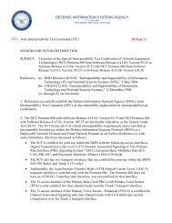
6. OPERATIONAL ARCHITECTURE. JITC tested the SUT under the F-NE Unified<br />
Capabilities Requirements (UCR) product category. A high-level Defense Information<br />
Systems Network (DISN) node architecture, as depicted in Figure 2-1, displays the<br />
devices in the DISN architecture. The SUT can be deployed to provide connectivity<br />
between legacy serial data, video, and voice services over Ethernet, Plesiochronous<br />
Digital Hierarchy (PDH), Synchronous Optical Networking, Fiber Channel, and Wide<br />
Area Networks (WAN); and provide remote switching for working devices to<br />
preconfigured backup devices during maintenance or failures. The SUT meets the UCR<br />
requirements and can be used to augment WAN or Local Area Network (LAN)<br />
infrastructures.
DISN Backbone<br />
HAIPE/<br />
LEF<br />
DISN Router<br />
S-CE<br />
AGF-P<br />
(MSPP)<br />
C/P/S Edge<br />
C/P/S<br />
F-NE(s)<br />
DISN Router<br />
U-CE<br />
OTS-P<br />
(OLA, Transponder,<br />
Muxponder, ROADM)<br />
HAIPE/<br />
LEF<br />
OTS<br />
(OLA, Transponder,<br />
Muxponder, ROADM)<br />
DISN Router<br />
S-AR<br />
DISN Router<br />
S-CE<br />
LEGEND:<br />
AAF-P Access Aggregation Function Product<br />
AGF-P Access Grooming Function Product<br />
AR Aggregation Router<br />
BITS Background Intelligent Transfer Service<br />
C/P/S Camp, Post, or Station<br />
DISN Defense Information System Network<br />
F-NE Fixed Network Element<br />
HAIPE High Assurance Internet Protocol Encryptor<br />
LEF Link Encryption Family<br />
MSPP Multi-Service Provisioning Platform<br />
MUX Multiplexer<br />
OLA Optical Line Amplifier<br />
AGF-P<br />
(MSPP)<br />
F-NE(s)<br />
C/P/S Edge<br />
C/P/S<br />
DISN Router<br />
U-AR<br />
DISN Router<br />
U-CE<br />
2-2<br />
OTS-P<br />
(OLA, Transponder,<br />
Muxponder, ROADM)<br />
BITS<br />
TSF-P<br />
(ODXC)<br />
AGF-P<br />
(MSPP)<br />
HAIPE/<br />
LEF<br />
DISN Router<br />
S-PE<br />
DISN Router<br />
S-AR<br />
DISN Router<br />
S-CE<br />
Figure 2-1. DISN Architecture<br />
C/P/S Edge<br />
C/P/S<br />
DISN Router<br />
P<br />
F-NE(s)<br />
DISN Router<br />
U-PE<br />
DISN Router<br />
U-AR<br />
DISN Router<br />
U-CE<br />
F-NE(s)<br />
AAF-P<br />
(TDM MUX)<br />
OTS-P Optical Transport System Product<br />
P Provider Router<br />
ROADM Reconfigurable Optical Add and Drop Multiplexer<br />
S-AR Secret Aggregation Router<br />
S-CE Secret Customer Edge Router<br />
S-PE Secret Provider Edge Router<br />
TDM Time Division Multiplexing<br />
T-PE Transport Provider Edge Router<br />
TSF-P Transport Switch Function Product<br />
U-AR Unclassified Aggregation Router<br />
U-CE Unclassified Customer Edge Router<br />
U-PE Unclassified Provider Edge Router
7. INTEROPERABILITY REQUIREMENTS. The interface, Capability Requirements<br />
(CR), Functional Requirements (FR), Information Assurance (IA), and other<br />
requirements for NE products are established by Sections 5.4 and 5.9 of the<br />
Department of Defense UCR 2008, Change 2.<br />
7.1 Interfaces. The F-NE products use its interfaces to connect to LAN or DISN WAN<br />
infrastructure. The threshold requirements for interfaces specific to the F-NE products<br />
are listed in Table 2-1.<br />
Interface<br />
Critical<br />
(See note 1.)<br />
Table 2-1. NE Interface Requirements<br />
UCR Ref<br />
(UCR 2008,<br />
Change 2)<br />
Threshold<br />
CR/FR (See<br />
note 2.)<br />
Analog No 5.9.2.3.1<br />
Ingress (LAN side)<br />
1, 2, and 4<br />
Serial No 5.9.2.3.2 1, 2, and 4<br />
BRI ISDN<br />
DS1<br />
E1<br />
DS3<br />
No<br />
No<br />
No<br />
No<br />
5.9.2.3.3<br />
5.9.2.3.4<br />
5.9.2.3.5<br />
5.9.2.3.6<br />
1, 2, and 4<br />
1, 2, 3, and 4<br />
1, 2, 3, and 4<br />
1, 2, 3, and 4<br />
Meet minimum<br />
CR/FRs and<br />
interface standards.<br />
OC-X No 5.9.2.3.8 1, 2, 3, and 4<br />
IP (Ethernet) No 5.9.2.3.9 1, 2, 4, and 7<br />
Egress (WAN side)<br />
Serial No 5.9.2.3.2 1, 2, 3, and 4<br />
DS1 No 5.9.2.3.4 1, 2, 3, and 4<br />
E1<br />
DS3<br />
OC-X<br />
IP<br />
(Ethernet)<br />
No<br />
No<br />
No<br />
No<br />
5.9.2.3.6<br />
5.9.2.3.6<br />
5.9.2.3.8<br />
5.9.2.3.9<br />
1, 2, 3, and 4<br />
1, 2, 3, and 4<br />
1, 2, 3, and 4<br />
1, 2, 4, and 7<br />
Meet minimum<br />
CR/FRs and<br />
interface standards.<br />
DLoS No 5.9.2.3.9 1, 2, 3, 4, and 5<br />
NM<br />
10Base-X Yes 5.3.2.4.4 8 Meet minimum<br />
100Base-X Yes 5.3.2.4.4 8<br />
CR/FRs and<br />
interface standards.<br />
2-3<br />
Criteria Remarks<br />
Provides access to<br />
local infrastructure.<br />
Provides access to<br />
local infrastructure.<br />
Provides access to<br />
local infrastructure.<br />
NOTES:<br />
1. UCR does not specify any minimum interfaces. The SUT must minimally provide one of the listed ingress and egress<br />
interfaces specified.<br />
2. CR/FR requirements are contained in Table 2. CR/FR numbers represent a roll-up of UCR requirements.<br />
LEGEND:<br />
100Base-X 100 Mbps Ethernet generic designation<br />
10Base-X 10 Mbps Ethernet generic designation<br />
BRI Basic Rate Interface<br />
CR Capability Requirement<br />
DLoS Direct Line of Sight<br />
DS1 Digital Signal Level 1 (1.544 Mbps)<br />
DS3 Digital Signal Level 3 (44.736 Mbps)<br />
E1 European Interface Standard (2.048 Mbps)<br />
FR Functional Requirement<br />
IP Internet Protocol<br />
ISDN Integrated Services Digital Network<br />
LAN Local Area Network<br />
Mbps Megabits per second<br />
NE Network Element<br />
NM Network Management<br />
OC-X Optical Carrier - X (OC-3, OC-12, etc.,)<br />
SUT System Under <strong>Test</strong><br />
UCR Unified Capabilities Requirements<br />
WAN Wide Area Network
7.2 CR and FR. The F-NE products have required and conditional features and<br />
capabilities that are established by UCR 2008, Change 2, Section 5.9. The SUT does<br />
not need to provide non-critical (conditional) features and capabilities. If they are<br />
present; however, they must function according to the specified requirements. Table 2-<br />
2 lists the features and capabilities and their associated requirements for SUT product.<br />
Table 3-1 of Enclosure 3 provides detailed CR/FR requirements.<br />
CR/FR<br />
ID<br />
1<br />
2<br />
3<br />
4<br />
5<br />
Capability/Function Applicability<br />
(See note)<br />
Table 2-2. SUT CRs and FRs<br />
UCR Ref<br />
(UCR 2008,<br />
Change 2)<br />
2-4<br />
Criteria Remarks<br />
General NE Requirements<br />
General Requirements Required 5.9.2.1 Meet applicable UCR<br />
Alarms Required 5.9.2.1.1 requirements. Detailed<br />
requirements and<br />
Congestion Control<br />
& Latency<br />
Compression<br />
Required 5.9.2.1.2<br />
associated criteria are<br />
provided in Table 3-1 of<br />
Enclosure 3.<br />
G.726 Conditional 5.9.2.2 Meet applicable UCR<br />
G.728 Conditional 5.9.2.2 requirements. Detailed<br />
requirements and<br />
G.729<br />
Interface Requirements<br />
Conditional 5.9.2.2<br />
associated criteria are<br />
provided in Table 3-1 of<br />
Enclosure 3.<br />
Timing<br />
Device Management<br />
Required 5.9.2.3.7<br />
Meet UCR<br />
requirements.<br />
Management Options Required 5.9.2.4.1 Meet applicable UCR<br />
Fault Management<br />
Loop-Back Capability<br />
Conditional<br />
Conditional<br />
5.9.2.4.2<br />
5.9.2.4.3<br />
requirements. Detailed<br />
requirements and<br />
associated criteria are<br />
Operational Configuration<br />
Restoral<br />
DLoS<br />
Required 5.9.2.4.4<br />
provided in Table 3-1 of<br />
Enclosure 3.<br />
DLoS Transport Conditional 5.9.2.4.5<br />
Meet UCR DLoS<br />
requirements.<br />
.<br />
Applicable to TDM<br />
interfaces.<br />
.
CR/FR<br />
ID<br />
6<br />
7<br />
Capability/Function<br />
IPv6 Requirements<br />
Table 2-2. SUT CRs and FRs (continued)<br />
Applicability<br />
(See note)<br />
2-5<br />
UCR Ref<br />
(UCR 2008,<br />
Change 2)<br />
Product Requirements Required 5.3.5.4<br />
NM Requirements<br />
VVoIP NMS Interface<br />
Requirements<br />
General Management<br />
Requirements<br />
Required 5.3.2.4.4<br />
Required 5.3.2.17.2<br />
Criteria Remarks<br />
Meet UCR IPv6<br />
requirements.<br />
Meet applicable<br />
UCR requirements.<br />
Detailed<br />
requirements and<br />
associated criteria<br />
are provided in<br />
Table 3-1 of<br />
Enclosure 3.<br />
NOTE: Annotation of ‘required’ refers to high-level requirement category. Applicability of each sub-requirement is provided in<br />
enclosure 3.<br />
LEGEND:<br />
ADPCM Adaptive Differential Pulse Code Modulation<br />
CR Capabilities Requirement<br />
CS-ACELP Conjugate Structure Algebraic Code-Excited<br />
Linear Prediction<br />
DLoS Direct Line of Sight<br />
D-NE Deployed Network Element<br />
FR Functional Requirement<br />
G.726 ITU-T speech codec for ADPCM (32 Kbps)<br />
G.728 ITU-T speech codec for LD-CELP (16 Kbps)<br />
G.729 ITU-T speech codec for CS-ACELP (8 Kbps)<br />
ID Identification<br />
IP Internet Protocol<br />
IPv4 Internet Protocol version 4<br />
7.3 Other. None.<br />
IPv6 Internet Protocol version 6<br />
ITU-T International Telecommunication Union –<br />
Telecommunication<br />
Kbps Kilobits per second<br />
LD-CELP Low Delay-Code Excited Linear Prediction<br />
NE Network Element<br />
NM Network Management<br />
NMS Network Management System<br />
SUT System Under <strong>Test</strong><br />
TDM Time Division Multiplexing<br />
UCR Unified Capabilities Requirements<br />
VVoIP Voice and Video over Internet Protocol<br />
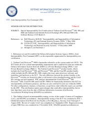
8. TEST NETWORK DESCRIPTION. The JITC tested the SUT at JITC Indian Head<br />
(IHD) Advanced Technology <strong>Test</strong> bed. Figure 2-3 through 2-6 show the multiple SUT<br />
connectivity for the UCR and interoperability test bed scenarios.
Voice/Data <strong>Test</strong> Set<br />
OC-48/192<br />
DISN Core Node 1<br />
Juniper<br />
M7i<br />
OC-48/192<br />
1 GE<br />
OC-192<br />
OC-192<br />
GE/10 GE<br />
Juniper<br />
T320 GE/10 GE<br />
OC-192<br />
OC-3/12/48<br />
1 GE Cisco<br />
15454<br />
OC-768<br />
Sycamore<br />
16K<br />
OC-48/192<br />
OC-48/192<br />
OC-48/192<br />
OC-192<br />
OC-768<br />
DISN-OTS<br />
Transporting DISN MSPP / ODXC / IP-Router<br />
OC-192<br />
LEGEND:<br />
Agilent Vendor Name<br />
ATT Advanced Technologies <strong>Test</strong> Bed<br />
DISN Defense Information Systems Network<br />
DWDM Dense Wavelength Division Multiplexing<br />
GE Gigabit Ethernet<br />
IP Internet Protocol<br />
Ixia Vendor Name<br />
OC-3/12/48<br />
1 GE<br />
2-6<br />
DWDM<br />
Cisco<br />
15454<br />
Voice/Data <strong>Test</strong> Set<br />
<strong>Test</strong> Measurement and Diagnostic Equipment<br />
DISN Core Node 3<br />
Agilent Router<br />
<strong>Test</strong>er Chariot Console Ixia 400t Agilent Omniber<br />
DISN-OTS<br />
Transporting DISN MSPP / ODXC / IP-Router<br />
OC-192<br />
OC-192<br />
OC-48/192<br />
JDSU 8000<br />
DISN Core Node 2<br />
Juniper<br />
M7i<br />
1 GE<br />
Juniper<br />
T320<br />
GE/10 GE GE/10 GE<br />
OC-48/192<br />
OC-192<br />
OC-192<br />
Sycamore<br />
16K<br />
OC-48/192<br />
OC-48/192<br />
Cisco<br />
15454<br />
OC-192<br />
OC-48/192<br />
OC-3/12/48<br />
1 GE<br />
OC-768 OC-768<br />
JDSU Vendor Name<br />
MSPP Multi-Service Provisioning Platform<br />
OC Optical Carrier<br />
ODXC Optical Digital Cross Connect<br />
OTS Optical Transport System<br />
Figure 2-2. ATT Lab <strong>Test</strong> Bed<br />
Voice/Data <strong>Test</strong> Set
Serial-Data<br />
Generator<br />
2/4 wire Analog<br />
Modems<br />
PBX-Voice-T1<br />
ONPATH Technologies 2900<br />
JITC Certification Network Diagram<br />
Project Tracking Number: 1028501<br />
CCU Shelf:<br />
232-DTE/DCE<br />
530A-DTE/DCE<br />
T1<br />
2/4 Wire-Analog<br />
V.35<br />
LEGEND:<br />
CCU Common Control Unit<br />
DCE Data Communications Equipment<br />
DTE Data Terminal Equipment<br />
JITC <strong>Joint</strong> <strong>Interoperability</strong> <strong>Test</strong> <strong>Command</strong><br />
Serial<br />
<strong>Test</strong> Configuration<br />
2-7<br />
SUT<br />
2900<br />
SWITCH<br />
UCMS<br />
1.2 &<br />
Vista<br />
Near End<br />
Server<br />
CCU Shelf:<br />
232-DTE/DCE<br />
530A-DTE/DCE<br />
T1<br />
2/4 Wire-Analog<br />
V.35<br />
Serial-Data<br />
Generator<br />
2/4 wire Analog<br />
Modems<br />
PBX-Voice-T1<br />
PBX Private Branch Exchange<br />
SUT System Under <strong>Test</strong><br />
T1 Transmission Link Level 1<br />
UCMS Unified Communications Management Suite<br />
Figure 2-3. ONPATH Systems Serial and Analog Configuration
Ethernet <strong>Test</strong>er<br />
VoIP <strong>Test</strong>er<br />
IPv4/IPv6 <strong>Test</strong>er<br />
LEGEND:<br />
E Ethernet<br />
GbE Gigabit Ethernet<br />
IPv4<br />
IPv6<br />
Internet Protocol Version 4<br />
Internet Protocol Version 6<br />
ONPATH Technologies 2900<br />
JITC Certification Network Diagram<br />
Project Tracking Number: 1028501<br />
10/100/1000E Copper<br />
1GbE Fiber<br />
10GbE Fiber<br />
Optical / Copper<br />
Ethernet<br />
<strong>Test</strong> Configuration<br />
SUT<br />
2900<br />
SWITCH<br />
UCMS<br />
1.2 &<br />
Vista<br />
Near End<br />
Server<br />
2-8<br />
10/100/1000E Copper<br />
1GbE Fiber<br />
10GbE Fiber<br />
Ethernet <strong>Test</strong>er<br />
VoIP <strong>Test</strong>er<br />
IPv4/IPv6 <strong>Test</strong>er<br />
JITC <strong>Joint</strong> <strong>Interoperability</strong> <strong>Test</strong> <strong>Command</strong><br />
SUT System Under <strong>Test</strong><br />
UCMS Unified Communications Management Suite<br />
VoIP Voice Over Internet Protocol<br />
Figure 2-4. ONPATH Systems Ethernet and VoIP Configuration
SONET Data<br />
Generator<br />
(Fiber Ports)<br />
ONPATH Technologies 2900<br />
JITC Certification Network Diagram<br />
Project Tracking Number: 1028501<br />
OC-3/12/48<br />
LEGEND:<br />
OC Optical Carrier<br />
JITC <strong>Joint</strong> <strong>Interoperability</strong> <strong>Test</strong> <strong>Command</strong><br />
UCMS Unified Communications Management Suite<br />
Optical-SONET<br />
<strong>Test</strong> Configuration<br />
2-9<br />
SUT<br />
2900<br />
SWITCH<br />
UCMS<br />
1.2 &<br />
Vista<br />
Near End<br />
Server<br />
SONET<br />
SUT<br />
OC-3/12/48<br />
Synchronous Optical Networking<br />
System Under <strong>Test</strong><br />
Figure 2-5. ONPATH Systems SONET Configuration<br />
Loopback
Multiple Type<br />
Data Generators<br />
(Copper/Fiber<br />
Ports)<br />
DISN-MSPP<br />
DISN-ODXC<br />
DISN-IP-Router<br />
ONPATH Technologies 2900<br />
JITC Certification Network Diagram<br />
Project Tracking Number: 1028501<br />
10/100/1000E Copper<br />
1GbE Fiber<br />
10GbE Fiber<br />
OC-3/12/48<br />
LEGEND:<br />
E Ethernet<br />
DISN Defense Information Systems Network<br />
GbE Gigabit Ethernet<br />
IOP <strong>Interoperability</strong><br />
DISN <strong>Interoperability</strong><br />
<strong>Test</strong> Configuration<br />
2900<br />
SWITCH<br />
UCMS<br />
1.2 &<br />
Vista<br />
Near End<br />
Server<br />
2-10<br />
10/100/1000E Copper<br />
1GbE Fiber<br />
10GbE Fiber<br />
OC-3/12/48<br />
SUT<br />
DISN-MSPP<br />
DISN-ODXC<br />
DISN-IP-Router<br />
IP Internet Protocol<br />
JITC <strong>Joint</strong> <strong>Interoperability</strong> <strong>Test</strong> <strong>Command</strong><br />
MSPP Multiple-Service Provisioning Platform<br />
ODXC Optical Digital Cross Connect<br />
UCMS Unified Communications Management Suite<br />
Figure 2-6. ONPATH Systems DISN-IOP Configuration<br />
Multiple Type<br />
Data Generators<br />
(Copper/Fiber<br />
Ports)<br />
9. SYSTEM CONFIGURATION. Table 2-4 lists the tested SUT configuration shown in<br />
Figure 2-2, Table 2-5 lists the Non-SUT equipment used to test the SUT Figure 2-2, and<br />
Table 2-6 lists the test equipment used to generate voice, Synchronous Optical<br />
Network, and IP traffic.<br />
Table 2-4. <strong>Test</strong>ed SUT Equipment<br />
Platform Software Release Function<br />
ONPATH UCS-2900 1.2.3.1 Universal Connectivity System Switch<br />
ONPATH UCMS-120-001 UCMS 1.2 System Management Software<br />
LEGEND:<br />
SUT System Under <strong>Test</strong><br />
UCS Universal Internet Protocol Connectivity System<br />
UCMS<br />
Universal Connectivity Management System
Table 2-5. Non-SUT Equipment<br />
Component Software Version Function<br />
ETH 100T-12-G, OC-3IR-STM-1 SH-1310-8, OC-12IR-STM-<br />
Cisco 15454 09.00-008I-17.17<br />
4-1310-4, DS-1N-<strong>14</strong>, G1K-4, OC-192SR/STM-64, OC-48 AS-<br />
IR-1310, DS-3N-12E<br />
Sycamore ODXC 7.6.21 Build 0562.26.27.57.<strong>14</strong><br />
GPIC2 2 X OC-192/STM-64, GPIC 24 x OC-3-12/STM-1-4IR,<br />
GPIC2 8 x OC-48/STM-16, USC - OC-192 LR 2c LIM 1<br />
Juniper T320 Router 9.2.R2.15<br />
4 x FE 100 Base Tx, 10 x GbE LAN 1000 Base, 1x OC-192<br />
SM SR2, 1 x 10GbE LAN, XENPAK<br />
Juniper M7i 10.3.R4.4 4 x GbE LAN<br />
4 Port line card (MA0653-115)<br />
RedCom Switch 6.1<br />
2/ Multi E1/T1 (MET) Interface Board (MA0683-122<br />
3/ Single Slot System Processor (S3P) Board/ line signaling<br />
Protocol for trunk lines (GR303 or SS7)(MA0688-101)<br />
LEGEND:<br />
DS Digital Signal<br />
E1 European Carrier 1<br />
ETH Ethernet<br />
FE Front End<br />
GR Generic Requirement<br />
GbE Gigabit Ethernet<br />
GPIC Group Primary Interexchange Carrier<br />
IR Intermediate Reach<br />
LAN Local Area Network<br />
LIM Line Interface Module<br />
LR Long Reach<br />
MET Multi E1/T1<br />
Table 2-6. <strong>Test</strong> Equipment<br />
2-11<br />
OC Optical Carrier<br />
ODXC Optical Digital Cross Connect<br />
R Revision<br />
SM Single Mode<br />
SR Short Reach<br />
SS7 Signaling System 7<br />
STM Synchronous Transport Module<br />
SUT System Under <strong>Test</strong><br />
T1 Transmission Link Level 1<br />
Tx Transmit<br />
USC Universal Services Card<br />
Manufacturer Type Port Type Software Version<br />
Optical <strong>Test</strong>er<br />
1550 nm<br />
1310 nm<br />
A.06.01<br />
Agilent<br />
OC-3/OC-12 /POS<br />
Router <strong>Test</strong>er 900<br />
OC-48 Multilayer<br />
1000 Base X<br />
10 Gb LAN/WAN<br />
10/100/1000 Base-T<br />
6.11<br />
Agilent Rack Mounted Router <strong>Test</strong>er 900 1000 Base-X<br />
OC-48c POS<br />
OC-3/12/POS<br />
6.11<br />
OC-192 POS<br />
DSU<br />
6.11<br />
Agilent JDSU T-Berd 8000<br />
10/100/1000<br />
OC-3-12<br />
DS-3<br />
OC-192<br />
6.4<br />
LEGEND:<br />
DS Digital Signal<br />
DSU Data Services Unit<br />
Gb Gigabit<br />
JDSU Vendor Name<br />
LAN Local Area Network<br />
nm nanometer<br />
OC Optical Carrier<br />
POS Packet Over Synchronous Optical Network<br />
WAN Wide Area Network
10. TEST LIMITATIONS. None<br />
11. INTEROPERABILITY EVALUATION RESULTS. The SUT meets the critical<br />
interoperability requirements for F-NE and the JITC certifies it joint use within the DISN.<br />
Additional discussion regarding specific testing results is contained in subsequent<br />
paragraphs.<br />
11.1 Interfaces. The SUT’s interface status is provided in Table 2-7.<br />
Interface<br />
Table 2-7. SUT F-NE Interface Requirements Status<br />
Critical<br />
(See note 1.)<br />
UCR Ref<br />
(UCR 2008,<br />
Change 2)<br />
Threshold<br />
CR/FR<br />
(See note 2.)<br />
2-12<br />
Status Remarks<br />
Analog No 5.9.2.3.1<br />
Ingress (LAN side)<br />
1, 2, and 4 Certified<br />
SUT met requirements for<br />
specified interfaces.<br />
Serial No 5.9.2.3.2 1, 2, and 4 Certified<br />
SUT met requirements for<br />
specified interfaces.<br />
BRI ISDN No 5.9.2.3.3 1, 2, and 4 NA Not supported by the SUT.<br />
DS1 No 5.9.2.3.4 1, 2, 3, and 4 Certified<br />
SUT met requirements for<br />
specified interfaces.<br />
E1 No 5.9.2.3.5 1, 2, 3, and 4 NA Not supported by the SUT.<br />
DS3 No 5.9.2.3.6 1, 2, 3, and 4 NA Not supported by the SUT.<br />
SUT met requirements for<br />
OC-X No 5.9.2.3.8 1, 2, 3, and 4 Certified OC-3, OC-48 and OC-48<br />
SONET interfaces.<br />
IP<br />
(Ethernet)<br />
10/100/1000<br />
No 5.9.2.3.9 1, 2, 4, and 7<br />
Egress (WAN side)<br />
Certified<br />
SUT met requirements for<br />
specified interfaces.<br />
Analog No 5.9.3.2.1 1, 2, and 4 Certified<br />
SUT met requirements for<br />
specified interfaces.<br />
Serial No 5.9.2.3.2 1, 2, 3, and 4 Certified<br />
SUT met requirements for<br />
specified interfaces.<br />
DS1 No 5.9.2.3.4 1, 2, 3, and 4 Certified<br />
SUT met requirements for<br />
specified interfaces.<br />
E1 No 5.9.2.3.6 1, 2, 3, and 4 NA Not supported by the SUT.<br />
DS3 No 5.9.2.3.6 1, 2, 3, and 4 NA Not supported by the SUT.<br />
SUT met requirements for<br />
OC-X No 5.9.2.3.8 1, 2, 3, and 4 Certified OC-3, OC-48 and OC-48<br />
SONET interfaces.<br />
IP<br />
(Ethernet)<br />
10/100/1000<br />
No 5.9.2.3.9 1, 2, 4, and 7 Certified<br />
SUT met requirements for<br />
specified interfaces.<br />
DLoS No 5.9.2.3.9 1, 2, 3, 4, and 5<br />
NM<br />
NA Not supported by the SUT.<br />
10Base-X Yes 5.3.2.4.4 8 Certified SUT met NM requirements for<br />
100Base-X Yes 5.3.2.4.4 8 Certified<br />
specified interfaces.
Table 2-7. SUT Interface Requirements Status (continued)<br />
NOTES:<br />
1. UCR does not specify any minimum interfaces. The SUT must minimally provide one of the listed ingress and egress<br />
interfaces specified.<br />
2. CR/FR requirements are contained in Table 2. CR/FR numbers represent a roll-up of UCR requirements.<br />
LEGEND:<br />
100Base-X 100 Mbps Ethernet generic designation<br />
10Base-X 10 Mbps Ethernet generic designation<br />
BRI Basic Rate Interface<br />
CR Capability Requirement<br />
DLoS Direct Line of Sight<br />
DS1 Digital Signal Level 1 (1.544 Mbps)<br />
DS3 Digital Signal Level 3 (44.736 Mbps)<br />
E1 European Interface Standard (2.048 Mbps)<br />
F-NE Fixed Network Element<br />
FR Functional Requirement<br />
IP Internet Protocol<br />
2-13<br />
ISDN Integrated Services Digital Network<br />
LAN Local Area Network<br />
Mbps Megabits per second<br />
NA Not Applicable<br />
NM Network Management<br />
OC-X Optical Carrier - X (OC-3, OC-12, etc.,)<br />
SONET Synchronous Optical Networking<br />
SUT System Under <strong>Test</strong><br />
UCR Unified Capabilities Requirements<br />
WAN Wide Area Network<br />
11.2 CR and FR. The SUT’s CR/FR statuses are listed in Table 2-8. The detailed<br />
CR/FR requirements are provided in Table 3-1 of the System Functional and Capability<br />
Requirements (Enclosure 3).<br />
CR/FR<br />
ID<br />
1<br />
2<br />
3<br />
4<br />
5<br />
Capability/<br />
Function<br />
Table 2-8. SUT CRs and FRs Status<br />
Applicability<br />
(See note)<br />
UCR Ref<br />
(UCR 2008,<br />
Change 2)<br />
Status Remarks<br />
General NE Requirements<br />
General Requirements Required 5.9.2.1 Met<br />
Alarms Required 5.9.2.1.1 Met<br />
Congestion Control &<br />
Latency<br />
Compression<br />
Required 5.9.2.1.2 Met<br />
G.726 Conditional 5.9.2.2 NA Not supported by the SUT.<br />
G.728 Conditional 5.9.2.2 NA Not supported by the SUT.<br />
G.729<br />
Interface Requirements<br />
Conditional 5.9.2.2 NA Not supported by the SUT.<br />
Timing<br />
Device Management<br />
Required 5.9.2.3.7 Met<br />
Management Options Required 5.9.2.4.1 Met<br />
Fault Management Conditional 5.9.2.4.2 NA Not supported by the SUT.<br />
Loop-Back Capability Conditional 5.9.2.4.3 NA Not supported by the SUT.<br />
Operational Configuration<br />
Restoral<br />
DLoS<br />
Required 5.9.2.4.4 Met<br />
DLoS Transport Conditional 5.9.2.4.5 NA Not supported by the SUT.
CR/FR<br />
ID<br />
6<br />
7<br />
Table 2-8. SUT CRs and FRs Status (continued)<br />
Capability/ Function Applicability<br />
(See note)<br />
Proprietary IP Trunk<br />
Requirements<br />
UCR Ref<br />
(UCR 2008,<br />
Change 2)<br />
Conditional 5.9.3.7 Not <strong>Test</strong>ed<br />
Secure Call Handling Required 5.9.3.8 Not <strong>Test</strong>ed<br />
Voice Packet Multiplexing Conditional 5.9.3.9 Not <strong>Test</strong>ed<br />
IPv6 Requirements<br />
Product Requirements Required 5.3.5.4 Met<br />
NM Requirements<br />
VVoIP NMS Interface<br />
Requirements<br />
General Management<br />
Requirements<br />
Required 5.3.2.4.4 Met<br />
Required 5.3.2.17.2 Met<br />
2-<strong>14</strong><br />
Status Remarks<br />
Sponsor requested to test<br />
the SUT as a fixed NE.<br />
Sponsor requested to test<br />
the SUT as a fixed NE.<br />
Sponsor requested to test<br />
the SUT as a fixed NE.<br />
SUT is a layer-2 device<br />
and transports IPv4 and<br />
IPv6 traffic transparently.<br />
NOTES: Annotation of ‘required’ refers to high-level requirement category. Applicability of each sub-requirement is provided in<br />
Enclosure 3.<br />
LEGEND:<br />
ADPCM Adaptive Differential Pulse Code Modulation<br />
CR Capabilities Requirement<br />
CS-ACELP Conjugate Structure Algebraic Code-Excited<br />
Linear Prediction<br />
DLoS Direct Line of Sight<br />
D-NE Deployed Network Element<br />
FR Functional Requirement<br />
G.726 ITU-T speech codec for ADPCM (32 Kbps)<br />
G.728 ITU-T speech codec for LD-CELP (16 Kbps)<br />
G.729 ITU-T speech codec for CS-ACELP (8 Kbps)<br />
ID Identification<br />
IP Internet Protocol<br />
IPv4 Internet Protocol version 4<br />
a. General NE Requirements<br />
IPv6 Internet Protocol version 6<br />
ITU-T International Telecommunication Union –<br />
Telecommunication<br />
Kbps Kilobits per second<br />
LD-CELP Low Delay-Code Excited Linear Prediction<br />
NE Network Element<br />
NM Network Management<br />
NMS Network Management System<br />
SUT System Under <strong>Test</strong><br />
TDM Time Division Multiplexing<br />
UCR Unified Capabilities Requirements<br />
VVoIP Voice and Video over Internet Protocol<br />
(1) General Requirements. In accordance with (IAW) UCR 2008, Change<br />
2, Section 5.9.2.1 all NEs shall meet the following general requirements and conditions:<br />
(a) The introduction of an NE(s) shall not cause the End-to-End (E2E)<br />
average Mean Opinion Score (MOS) to fall below 4.0 as measured over any 5-minute<br />
time interval. The SUT met the MOS requirement as measured using test equipment<br />
and simulated voice information exchanges.<br />
(b) The introduction of an NE(s) shall not degrade the E2E measured<br />
bit error rate (BER) to no more than .03 percent from the baseline minimum E2E digital<br />
BER requirement which is not more than one error in 1x10 9 bits (averaged over a<br />
9-hour period). The SUT met the requirement as measured using test equipment and<br />
simulated information exchanges.
(c) The introduction of an NE(s) shall not degrade secure<br />
transmission for secure end devices as defined by UCR 2008, Change 2, Section<br />
5.2.12.6, and DoD Secure Communications Devices. The JITC tested secure<br />
information exchanges by using DoD Secure Communications Devices.<br />
(d) The NE(s) shall support a minimum modem transmission speed of<br />
9.6 kbps per second (kbps) across the associated NE(s). The JITC tested this<br />
information exchange by using a modem and simulated information exchanges with no<br />
noted issues.<br />
(e) The NE(s) shall support a minimum facsimile transmission speed<br />
of 9.6 kbps across the associated NE(s). The JITC tested this information exchanges<br />
by using a facsimile and simulated information exchanges with no noted issues.<br />
(f) The NE shall transport all call control signals transparently on an<br />
E2E basis. The JITC tested this information exchange by using an actual call control<br />
signal via a Private Branch Experience Transmission Link Level 1 call and simulated<br />
information exchanges with no noted issues.<br />
(2) Alarms. IAW UCR 2008, Change 2, paragraph 5.9.2.1.1, the NE shall<br />
be able to propagate Carrier Group Alarms (CGA) and IAW UCR 2008, paragraph<br />
5.2.1.5.7, Carrier Group Alarm, upon physical loss of the Time Division Multiplexing<br />
(TDM) interface. NEs that support IP ingress/egress traffic either as inbound or<br />
outbound NE traffic and/or transport between NE(s) shall support one or more of the<br />
following routing protocols: Link-State and/or Distance-Vector. So that the NE can<br />
notify the IP network (e.g., LAN, Metropolitan Area Network) the condition of its link<br />
state for transporting ingress IP traffic, namely operational or down. The SUT is a layer-<br />
1 device and it passes all the routing protocols, IP link states and all TDM alarms<br />
transparently between connecting end equipments, in addition, it provides loss of signal<br />
alarm in case of loss of connectivity events for connecting end equipments.<br />
(3) Congestion Control and Latency. IAW UCR 2008, the NE shall ensure<br />
that congestion and latency between paired NEs does not affect DISN calls in progress<br />
or subsequent calls. Call congestion and latency requirements are as follows:<br />
(a) Time Division Multiplexer/Multiplexing (TDM) Transport. The SUT<br />
is a layer-1 device and SUT provides transparent TDM Transport. Therefore, the<br />
following TDM transport requirements are not applicable to the SUT, instead these are<br />
the responsibility of connecting end equipments.<br />
1. A dynamic load control signal (e.g., contact closure) shall be<br />
provided to the DISN switch.<br />
2. Congestion is not possible in the NE by nature of its<br />
functioning (e.g., a TDM multiplexer or transcoder).<br />
2-15
3. A software capability in limiting the provisioning the ingress<br />
and egress interfaces making congestion impossible even under the worst congestion<br />
scenario. This can be done by limiting the bearer or aggregate provisioning.<br />
4. TDM Transport Latency. The addition of NEs with TDM<br />
transports shall not increase the one-way latency per NE pair when measured from end<br />
to end over any 5-minute period specified as follows:<br />
a. TDM ingress G.711 (non-secure calls) to nontranscoding<br />
G.711 TDM egress shall not increase delay more than 10 ms per NE pair<br />
as measured E2E.<br />
b. TDM ingress G.711 (non-secure calls) to transcoding<br />
TDM egress with compression codecs shall not increase delay by more than 100 ms<br />
per NE pair as measured E2E.<br />
c. TDM ingress G.711 (secure calls) to non-transcoding<br />
TDM egress G.711 shall not increase delay by more than 50 ms per NE pair as<br />
measured E2E.<br />
d. TDM ingress G.711 (secure calls) to transcoding TDM<br />
egress with compression codecs shall not increase delay by more than 250 ms per NE<br />
pair as measured E2E.<br />
(b) IP Transport. The NE(s) using IP transport shall implement IP<br />
congestion control. Congestion may be controlled by using Differentiated Services,<br />
which shall be capable of providing preferential treatment for call congestion over other<br />
media types and a capability to limit the provisioning of input, and output interfaces so<br />
congestion is impossible under the worst transport congestion scenario. The IP<br />
interface parameters subject to ingress/egress requirements shall be met. The SUT is a<br />
layer-1 device and it passes all IP traffic transparently, therefore, nothing listed above<br />
the IP transport requirement is applicable to the SUT, instead those are the<br />
responsibility of connecting end equipments.<br />
(c) Direct Line of Sight (DLoS) Transport. The SUT does not provide<br />
DLoS Transport.<br />
b. Compression. The SUT does not support Compression.<br />
c. Interface Requirements. Timing. The NE shall be able to derive timing<br />
signal from an internal source, an incoming digital signal, or an external source. This<br />
requirement applies to TDM interfaces only; IP interfaces do not need to meet this<br />
requirement.<br />
d. Device Management. The SUT shall provide the following device<br />
management functions:<br />
2-16
(1) Management Options. The NE devices are to be managed by at least<br />
one of the following:<br />
(a) A front or back panel and/or external console control capability<br />
shall be provided for local management and SUT supports only external console control<br />
capability. The SUT provides an external console capability.<br />
(b) Remote monitoring and management by the Advanced DSN<br />
Integrated Management Support System (ADIMSS). JITC did not verify management of<br />
the SUT by ADIMSS.<br />
(2) Fault Management. The SUT may (conditional) report any failure of<br />
self-test diagnostic function on non-active and active channels on a noninterference<br />
basis to the assigned Network Management System (NMS). JITC verified this<br />
conditional capability via Network Management (NM) testing.<br />
(3) Loop-Back Capability. This requirement applies to TDM interfaces<br />
only; the SUT does provide loop-back capabilities via its all interfaces.<br />
(4) Operational Configuration Restoral. Loss of power should not remove<br />
configuration settings. The SUT shall restore to the last customer-configured state<br />
before the power loss, without intervention when power is restored. JITC verified this<br />
capability via NM testing.<br />
e. DLoS. DLoS Transport. The SUT does not provide DLoS Transport.<br />
f. Internet Protocol version 6 (IPv6) Requirements.<br />
(1) Product Requirements. The SUT must meet UCR 2008, Change 2,<br />
Section 5.3.5.4 IPv6 requirements for Network Appliance/Simple Server. The SUT is a<br />
layer-1 device and transports IPv4 and IPv6 traffic transparently so requirements<br />
specific relating to layer 3 do not apply.<br />
g. NM Requirements. JITC verified the following NM requirements via a<br />
combination of testing and reviewing of the vendor submitted NM Letter of Compliance.<br />
(1) Voice and Video over Internet Protocol (VVoIP) NMS Interface<br />
Requirements. IAW UCR 2008, Change 2, paragraph 5.3.2.4.4 the physical interface<br />
between the DISA VVoIP Element Management System (EMS) and the network<br />
components (i.e., Local Session Controller, Multi-Function Soft Switch, Edge Border<br />
Controller, Customer Edge Router) is a 10/100Megabits per second Ethernet interface.<br />
The interface will work in either of the two following modes using auto-negotiation:<br />
Institute of Electrical and Electronics Engineers (IEEE), Ethernet Standard 802.3, 1993;<br />
or IEEE, Fast Ethernet Standard 802.3u, 1995.<br />
2-17
(2) General Management Requirements. IAW UCR 2008, Change 2,<br />
paragraph 5.3.2.17.2, the SUT must support Secure/Simple Network Management<br />
Protocol Version 3 format. A network appliance shall have Operations interfaces that<br />
provide a standard means by which management systems can directly or indirectly<br />
communicate with and, thus, manage the various network appliances in the DISN. The<br />
physical interface between the Local EMS and the VVoIP network components shall be<br />
an Ethernet connection as specified in UCR 2008, Change 2, paragraph 5.3.2.4.4, VoIP<br />
NMS Interface Requirements. The physical interface between the VVoIP EMS and the<br />
VVoIP network components shall also be an Ethernet connection as specified in, UCR<br />
2008, Change 2, paragraph 5.3.2.4.4. There shall be a local craftsperson interface<br />
(Craft Input Device for Operations Administration & Management for all VVoIP network<br />
components.)<br />
12. TEST AND ANALYSIS REPORT. In accordance with the Program Manager’s<br />
request, JITC did not prepare a detailed test report. JITC distributes interoperability<br />
information via the JITC Electronic Report Distribution system, which uses Non-secure<br />
Internet Protocol Router Network (NIPRNet) e-mail. More comprehensive<br />
interoperability status information is available via the JITC System Tracking Program<br />
(STP), which .mil/gov users can access on the NIPRNet at https://stp.fhu.disa.mil. <strong>Test</strong><br />
reports, lessons learned, and related testing documents and references are on the JITC<br />
<strong>Joint</strong> <strong>Interoperability</strong> Tool at http://jit.fhu.disa.mil (NIPRNet). Information related to DSN<br />
testing is on the Telecommunications Switched Services <strong>Interoperability</strong> website at<br />
http://jitc.fhu.disa.mil/tssi.<br />
2-18
Enclosure 3<br />
SYSTEM FUNCTIONAL AND CAPABILITY REQUIREMENTS<br />
The Network Elements (NE) and Fixed Network Elements have required and<br />
conditional features and capabilities that are established by the Unified Capabilities<br />
Requirements (UCR). The System Under <strong>Test</strong> (SUT) need not provide conditional<br />
requirements. If they are provided, they must function according to the specified<br />
requirements. The detailed Functional requirements (FR) and Capability Requirements<br />
for NEs are listed in Table 3-1. Detailed Information Assurance (IA) requirements are<br />
included in Reference (e) and are not listed below.<br />
Table 3-1. NE Capability/Functional Requirements Table<br />
ID Requirement<br />
1<br />
2<br />
3<br />
4<br />
5<br />
The introduction of an NE(s) shall not cause the E2E average MOS to fall below<br />
4.0 as measured over any 5-minute time interval.<br />
The introduction of an NE(s) shall not degrade the E2E measured BER to no more<br />
than .03 percent from the baseline minimum E2E digital BER requirement which is<br />
not more than one error in 1x109 bits (averaged over a 9-hour period).<br />
The introduction of an NE(s) shall not degrade secure transmission for secure end<br />
devices as defined by UCR 2008, Section 5.2.2, DoD Secure Communications<br />
Devices.<br />
The NE(s) shall support a minimum modem transmission speed of 9.6 kbps across<br />
the associated NE(s).<br />
The NE(s) shall support a minimum facsimile transmission speed of 9.6 kbps<br />
across the associated NE(s).<br />
UCR Ref<br />
(UCR 2008 CH 2)<br />
F-NE<br />
5.9.2.1 (1) R<br />
5.9.2.1 (2) R<br />
5.9.2.1 (3) R<br />
5.9.2.1 (4) R<br />
5.9.2.1 (5) R<br />
6 The NE shall transport all call control signals transparently on an E2E basis. 5.9.2.1 (6) R<br />
7<br />
7A<br />
7B<br />
7C<br />
[Conditional] The NEs that support a P2N capability shall meet the following<br />
additional requirements when deployed in a P2N architectural configuration:<br />
The aggregate egress from all NEs in the P2NP architecture must be<br />
identical to the aggregate ingress of all NEs in the same P2N architecture.<br />
However, if all or part of the P2N is operating in a P2MP mode that is applying<br />
multicast from a centrally designated NE to one or more of the associated<br />
peripheral NEs, the aggregate of the additional multicast traffic must be accounted<br />
for in the egress sum<br />
total.<br />
Excluding latency, the P2N AP shall be measured as though it is a P2P<br />
architecture at the P2N AP NE endpoints ingress and egress points. As such, the<br />
P2N AP must meet all the other stated requirements of a P2P.<br />
For a given P2N AP, the maximum latency allowed E2E, as measured<br />
over any 5-minute period at the P2N AP NE ingress and egress points, shall be 5<br />
ms or less, when added in addition to the expected P2P latency. Hence, as an<br />
example, if the expected P2P latency requirement for a P2N AP is 50 ms, then<br />
P2N AP maximum latency, regardless of the number of NE hops between the<br />
ingress and egress NEs, the measured value shall not exceed 55 ms.<br />
5.9.2.1 (7) C<br />
5.9.2.1 (7A) R<br />
5.9.2.1 (7B) R<br />
5.9.2.1 (7C) R
Table 3-1. NE Capability/Functional Requirements Table continued)<br />
ID Requirement<br />
8<br />
9<br />
9A<br />
9B<br />
9C<br />
The NE shall be able to propagate Carrier Group Alarms (CGAs) upon physical<br />
loss of the TDM interface. The NE shall provide the capability of detecting a carrier<br />
group alarm (CGA). When this alarm is detected, all associated outgoing trunks<br />
shall be made busy automatically to subsequent customer call attempts. Call<br />
attempts on associated incoming trunks shall not be processed. When possible,<br />
the Reverse Make Busy feature shall be exercised on incoming trunks. Voice<br />
switching systems using a TDM connection to an NE shall receive the<br />
proper CGAs from the NE upon loss of the transport link between NEs, regardless<br />
of whether the transport link is TDM, IP, or DLoS between the NEs. The NEs that<br />
support IP ingress or egress traffic either as inbound or outbound NE traffic and/or<br />
transport between NE(s) shall support one or more of the following routing<br />
protocols: Link-State and/or Distance-Vector, so the NE can notify the IP network<br />
(e.g., LAN, MAN), using one of these routing protocols, the condition of its link<br />
state for transporting ingress IP traffic, namely operational or down.<br />
The NE shall assure that congestion between paired NEs does not affect DSN<br />
calls in progress or subsequent calls. Call congestion handling shall be met in one<br />
or more of the following ways.<br />
The NE shall implement TDM congestion control via one of the following methods:<br />
A. A dynamic load control signal (e.g., contact closure) shall be provided to the<br />
DSN switch per the following requirements:<br />
(1) The NE shall provide the capability to handle Carrier Group Alarm (CGA)<br />
indications from the carrier systems/equipment using the E-telemetry interface<br />
(scan points) for the TDM interfaces provided (e.g., DS0, DS1, and/or OC-X), and,<br />
comply to the Telcordia Technologies GR-303-CORE, System Generic<br />
Requirements, Objectives, and Interface, December 2000, Issue 4 and Telcordia<br />
Technologies TR-NWT-000057 that specifies the use of an COTgenerated DC<br />
contact closure alarm to indicate an “all-accessible-channelsbusy” condition.<br />
(2) The NE when interfaced to the network that provides an E-telemetry interface<br />
type (scan points) for alarm management shall be capable of CGA management<br />
that is used to minimize the effects of carrier failures on switching systems and on<br />
service. CGA scan point (binary condition, i.e., “closed” contact for active and<br />
“opened” for inactive states) when “closed” should busy out the failed circuits,<br />
release customers from the failed circuits, and prevent the failed circuits from<br />
seizing the DSN trunk equipment and prevent the NE from seizing the failed<br />
circuits.<br />
(3) The DSN CGA System Operation can be divided into three parts, i.e., detection<br />
of the carrier failure, conditioning the failed trunk, and reaction of the switching<br />
equipment to the processing of the failure. Requirements for scan point CGA are:<br />
(a) Sense Point Interface: The switching system shall provide sense<br />
points to which external CGAs can be interfaced to, so that failure of<br />
the carrier equipment shall cause the trunks to be removed from service.<br />
(b) Call Processing Actions: Receipt of a CGA shall cause call processing to be<br />
aborted on associated trunks that are not in the talking state.<br />
(c) Trunk Conditioning: Receipt of a CGA shall cause the following<br />
actions on the affected trunks:<br />
(i) Idle trunks shall be removed from the idle list. Subsequent calls for service must<br />
be ignored for the duration of the CGA. Busy-back shall be returned on those<br />
incoming trunks, which are optioned for busy-back while in the out-of-service state<br />
and proper MLPP treatment shall be applied.<br />
(ii) Trunks in the talking state shall be monitored for disconnect, after which they<br />
are to be placed in the same state as described above for idle trunks.<br />
3-2<br />
UCR Ref<br />
(UCR 2008 CH 2)<br />
F-NE<br />
5.9.2.1.1 R<br />
5.9.2.1.2 R<br />
5.9.2.1.2.1 (1A1) C<br />
5.9.2.1.2.1 (1A2) C<br />
5.9.2.1.2.1 (1A3) C
Table 3-1. NE Capability/Functional Requirements Table (continued)<br />
ID Requirement<br />
9D<br />
10<br />
11<br />
12<br />
13<br />
<strong>14</strong><br />
(4) Restoration of Service: All trunks affected shall be returned to their previous<br />
state after the CGA is removed.<br />
B. Congestion is not possible in the NE by nature of its functioning (e.g., a TDM<br />
multiplexer or transcoder).<br />
C. A software capability in limiting the provisioning of the ingress and egress<br />
interfaces making congestion impossible even under the worst congestion<br />
scenario. This can be done by limiting the bearer or aggregate provisioning.<br />
2. The addition of NEs with TDM transports shall not increase the one-way latency<br />
per NE pair when measured from end to end over any 5-minute period specified<br />
as follows:<br />
a. Time Division Multiplexing ingress G.711 (nonsecure calls) to nontranscoding<br />
G.711 TDM egress shall not increase delay more than 10 ms per NE pair as<br />
measured end-to-end.<br />
b. Time Division Multiplexing ingress G.711 (nonsecure calls) to transcoding TDM<br />
egress with compression codecs (Section 5.9.2.2, Compression) shall not increase<br />
delay by more than 100 ms per NE pair as measured end-to-end.<br />
c. Time Division Multiplexing ingress G.711 (secure calls) to nontranscoding TDM<br />
egress G.711 shall not increase delay by more than 50 ms per NE pair as<br />
measured end-to-end.<br />
d. Time Division Multiplexing ingress G.711 (secure calls) to transcoding TDM<br />
egress with compression codecs (Section 5.9.2.2, Compression) shall not increase<br />
delay by more than 250 ms per NE pair as measured end-to-end.<br />
The NE(s) using IP transport shall implement IP congestion control. Congestion<br />
may be controlled by using DiffServ, which shall be capable of providing<br />
preferential treatment for call congestion over other media types IAW Section<br />
5.3.3, Network Infrastructure End-to-<br />
End Performance Requirements, and a capability to limit the provisioning of input<br />
and output interfaces so congestion is impossible under the worst transport<br />
congestion scenario. The IP interface parameters subject to ingress or egress<br />
requirements shall be met IAW Section 5.9.2.3.9, IP Interface.<br />
The NE shall implement DLoS congestion control based on the DSN traffic and<br />
signaling type to be transported. (Please see Following)<br />
The NE transporting only TDM bearer and signaling traffic shall implement DLoS<br />
congestion control via one or more of the following methods:<br />
a. A dynamic load control signal (e.g., contact closure).<br />
b. Congestion is not possible in the NE so the maximum ingress throughput into<br />
the NE is configured so it does not exceed the DLoS link maximum egress<br />
transport capability to include all DLoS overhead control traffic between the<br />
transport devices.<br />
c. A software capability in limiting the provisioning of the ingress and egress<br />
interfaces making congestion impossible even under the worst congestion<br />
scenario. This can be done by limiting the bearer or aggregate provisioning.<br />
The NE transporting only ingress IP traffic, and using a DLoS transport,<br />
excluding 802.11, and/or 802.16 series standards, -shall implement DLoS IP<br />
congestion control per Section 5.9.2.1.2.2, For IP Transport. Additionally, IP<br />
congestion control may include a standards-based or proprietary protocol between<br />
the NEs that will adjust the QoS of the NE based on DLoS transport monitoring<br />
feedback to the NE to accommodate for changing environmental link conditions.<br />
3-3<br />
UCR Ref<br />
(UCR 2008 CH 2)<br />
5.9.2.1.2.1 (1A4, 1B,<br />
1C)<br />
5.9.2.1.2.1 (2A, 2B,<br />
2C, 2D)<br />
F-NE<br />
C<br />
C<br />
5.9.2.1.2.2 C<br />
5.9.2.1.2.3 C<br />
5.9.2.1.2.3 (1A, 1B,<br />
1C)<br />
C<br />
5.9.2.1.2.3 (2) C
Table 3-1. NE Capability/Functional Requirements Table (continued)<br />
ID Requirement<br />
15<br />
16<br />
17<br />
18A<br />
18B<br />
18C<br />
19<br />
The NE transporting both TDM and IP ingress traffic simultaneously over the same<br />
DLoS transport link shall meet the following requirements:<br />
a. [Required] The NE shall provide congestion control so it provides the same level<br />
of capability, respectively, for the appropriate traffic type, TDM and IP, per the<br />
requirements for single traffic type ingress or egress to the NE. Additionally, the<br />
congestion control may include a standards-based or proprietary protocol between<br />
the NEs that will adjust the QoS of the NE based on DLoS transport monitoring<br />
feedback to the NE to accommodate for changing environmental link conditions.<br />
b. [Conditional] The use of DLoS transport shall not increase the one-way latency<br />
or packet delay per the requirements for TDM ingress and TDM or IP egress<br />
interfaces per the appropriate Section 5.9.2.1.2.1, For TDM Transport, and Section<br />
5.9.2.3.9, IP Interface, respectively.<br />
The NE used for voice compression shall support at least one of the following<br />
standards:<br />
• ITU-T Recommendation G.726<br />
• ITU-T Recommendation G.728<br />
• ITU-T Recommendation G.729<br />
If provided, the NE shall provide for a 2-wire and/or 4-wire analog trunk<br />
circuit(s) interface that interfaces using industry standard signaling and facility<br />
arrangements per one or more of the following:<br />
1. E&M Trunk Circuits: The NE shall interface with exchange carriers using<br />
industry standard E&M signaling. The switching system shall interface with Type I<br />
and Type II E&M signaling in accordance with paragraph 9 and subparagraphs of<br />
GR-506-CORE. The switching system shall interface with Type V E&M signaling<br />
as defined in Paragraphs 6.8.5, 6.8.6, 6.8.7.2, 6.8.8.2, and 6.8.8.3 of Telcordia<br />
Technologies Document SR-2275. The DSN switch analog trunk interface shall<br />
always originate on the M-lead.<br />
2. Single Frequency Trunk Circuits: The NE will interface with external switching<br />
facility (SF) equipment using a 4-wire E&M trunk circuit, either Type I or II. The<br />
DSN in-band signaling equipment utilizing SF will place a 2600 Hz tone on the<br />
circuit to indicate the idle state (on-hook) and the tone will be removed from the<br />
circuit to indicate the busy state (off-hook). Signaling states will be conveyed via E<br />
and M leads (Type I or II) to the telephone equipment terminating the circuit on the<br />
equipment side of the interface. The SF trunk interface consists of only the voice<br />
path conductors (T, R, T1, R1), but at a point between this transmission facility<br />
interface and the switching function the SF signal will be translated back to the<br />
two-state dc signals.<br />
3. Dual Frequency Trunk Circuits: The Dual Frequency Signaling Unit (DFSU)<br />
equipment used in the DSN operates in much the same way as an SF unit, except<br />
that whenever the 2600 Hz tone is removed from the circuit a 2800 Hz tone is<br />
applied for a short period (175 ms maximum). The 2800 Hz tone burst will serve<br />
as a confirmation tone; the receiving signaling unit will only transition from on-hook<br />
to off-hook if the loss of the 2600 Hz tone is followed by the 2800 Hz tone. This<br />
prevents false on-hook to off-hook transitions from occurring due to a break in the<br />
communications circuit. Like the SF trunk interface, the DF<br />
trunk interface will consist of only the voice path conductors (T, R, T1, R1). The<br />
NE shall interface an external DFSU using a 4-wire E&M trunk circuit with Type I<br />
or II E&M signaling. This connection is on the equipment-side of a DF trunk<br />
interface.<br />
The NE used for serial interface connections shall be in accordance with one of<br />
the following standards:<br />
• ITU-T Recommendation V.35<br />
• TIA-232-F<br />
• EIA-449-1<br />
• TIA-530-A<br />
3-4<br />
UCR Ref<br />
(UCR 2008 CH 2)<br />
F-NE<br />
5.9.2.1.2.3 (3A, 3B) C<br />
5.9.2.2 C<br />
5.9.2.3.1 C<br />
5.9.2.3.1 (1) C<br />
5.9.2.3.1 (2) C<br />
5.9.2.3.1 (3) C<br />
5.9.2.3.2 C
Table 3-1. NE Capability/Functional Requirements Table (continued)<br />
ID Requirement<br />
20<br />
21<br />
22A<br />
22B<br />
The ISDN BRI interface shall meet the requirements and conditions IAW Section<br />
5.3.2.31.2, National ISDN 1/2 Basic Access.<br />
If provided, the NE shall meet the following DS1 (T1) interface requirements and<br />
conditions of a PCM-24 Digital Trunk Interface.<br />
PCM-24 Digital Trunk Interface: An NE shall provide a PCM-24 channel digital<br />
interface with<br />
a 1.544 Mbps T1 bit stream configured in either the D3/D4 (Superframe) framing<br />
format or the D5 Extended Superframe (ESF) framing format. D5 is also referred<br />
to as Extended Frame (EF). The same framing format shall be used in both<br />
directions of transmission. Voice signals shall be encoded in the 8-bit μ (255<br />
quantized values) pulse code modulation (PCM) encoding law. Supervisory and<br />
dial pulse (DP) signals shall utilize the A and B bits of the D3/D4 format or the A,<br />
B, C, and D bits of the D5 format for pre-CCS7 configurations. Voice channel<br />
address inband signaling shall be provided on individual channels. The D5 format<br />
shall be the preferred and system “goal” digital framing format and shall be<br />
provided in accordance with MIL-STD-187-700.<br />
1. Interface Characteristics: The NE shall use the DS1 24 channel standard<br />
interface as specified in ANSI T1.102, “Digital Hierarchy – Electrical Interfaces.”<br />
Table 5.9.2.3.4-1, PCM-24 Electrical Interface Characteristics, provides the<br />
electrical characteristics at the interface. Table 5.9.2.3.4-2 and Table 5.9.2.3.4-3<br />
provide a listing of the framing characteristics. (Please see UCR 2008, Change-2-<br />
Pages 1898 thru 1900)<br />
2. Supervisory Channel Associated Signaling: On-hook and off-hook status of<br />
each channel is transmitted and derived from the coding of the “A” and “B”<br />
signaling bits. Trunk seizure, answer supervision, dial pulse digits (DPs),<br />
preemption signals, and all other trunk supervisory information shall be sent and<br />
received on a per-channel basis using this scheme. Per-trunk signaling in the DSN<br />
switching system shall control the value of the “A” and “B” bits to indicate an onhook<br />
(“A” = 0, “B” = 0) or an off-hook (“A” = 1, “B” = 1) condition. When receiving<br />
supervisory status on digital trunks using the PCM-24 format, the DSN switching<br />
system shall interpret the combination of the “A” bit = 0 and<br />
the “B” bit = 0 as on-hook, and the combination bit = 1 and “B” bit = 1 as an offhook<br />
indication. When signaling on Voice Frequency (VF) channels using the<br />
PCM-24 format, the least significant bit of each channel, every six frames, shall<br />
carry signaling information.<br />
Utilizing the four-state signaling option of the Superframe (D3) format, frame 6<br />
shall contain the “A” channel signaling information and frame 12 shall contain the<br />
“B” channel signaling information. The switching system shall also interpret the<br />
combination of “A” bit = 1, “B” bit = 0, with bit position 2 in all 24 channels in the<br />
Superframe (D3) format equal to “0” as a channel alarm indication and shall also<br />
interpret the combination of “A” bit = 1, “B” bit = 0 as a remote make busy.<br />
In the ESF format ANSI defines a sixteen-state signaling option that labels the<br />
signaling bits “A” (frame 6), “B” (frame 12), “C” (frame 18), and “D” (frame 24).<br />
Because DSN does not require the “C” and “D” signaling channels the four-state<br />
option shall be used to allow changes in “A” and “B” signaling states to be<br />
transmitted twice as often. Utilizing<br />
Frames 6 and 18 in the 24-frame Extended Superframe shall contain the “A”<br />
channel signaling information; frames 12 and 24 shall contain the “B” channel<br />
signaling information.<br />
3. Clear Channel Capability: The NE shall be capable of transmitting and receiving<br />
B8ZS line coding in accordance with MIL-STD-187-700.<br />
3-5<br />
UCR Ref<br />
(UCR 2008 CH 2)<br />
F-NE<br />
5.9.2.3.3 C<br />
5.9.2.3.4 C<br />
5.9.2.3.4 (2) C<br />
5.9.2.3.4 (3) C
Table 3-1. NE Capability/Functional Requirements Table (continued)<br />
ID Requirement<br />
22C<br />
23<br />
23A<br />
23B<br />
24<br />
25<br />
26<br />
4. Alarm and Restoral Requirements: The NE shall provide the alarm and restoral<br />
features on the digital interface unit (DIU) as defined in Table5.9.2.3.4-4, PCM-24<br />
Alarm and Restoral Requirements. (Please see UCR 2008, Change-2-Page 1901)<br />
If provided, the NE shall meet the following E1 interface requirements and<br />
conditions of a PCM-30 Digital Trunk Interface: PCM-30 Digital Trunk Interface:<br />
The NE shall provide PCM-30 digital interfaces at a data rate of 2.048 Mbps. The<br />
PCM-30 interfaces shall meet the requirements of ITU-T Recommendation G.703<br />
and ITU-T Recommendation G.732. Voice signals in the PCM-30 framing format<br />
shall utilize the A-law encoding technique in accordance with ITU-T<br />
Recommendation G.772 (REV), “Protected Monitoring Points on Digital<br />
Transmission Systems.” The pertinent requirements for the PCM-30 interface are<br />
summarized in Table 5.9.2.3.5-1, PCM-30 Electrical Interface Characteristics.<br />
(Please see UCR 2008, Change-2-Page 1902)<br />
1. Supervisory Channel Associated Signaling: When receiving supervisory status<br />
on digital trunks using the PCM-30 format, the DSN switching system shall<br />
interpret the combination of the “A” signaling channel bit = 1 and the “B” signaling<br />
channel bit = 1 as on-hook, and<br />
shall interpret the combination of the “A” signaling channel bit = 0 and the “B”<br />
signaling channel bit = 1 as an off-hook indication. The DSN switching system<br />
shall also interpret the combination of “A” bit = 1 and “B” bit = 0 as a channel alarm<br />
indication and a remote make busy. Bits “C” and “D” are not used in the DSN for<br />
signaling or control and therefore shall be set to the values “C” = 0 and “D” =1 in<br />
accordance with ITU-T Recommendation G.704.<br />
2. Alarm and Restoral Requirements: The NE shall provide the alarm and restoral<br />
features on the DIU in order to be compatible with PCM-30 facilities and terminal<br />
equipment, as shown in Table 5.9.2.3.5-3, PCM-30 Alarm and Restoral<br />
Requirements. (Please see UCR 2008, Change-2-Page 1903)<br />
The DS3 interface shall meet the following requirements and conditions. Frame<br />
structure shall include M13 framing in accordance with ANSI T1.107-2002.<br />
Frame structure may include C-bit parity application in accordance with ANSI<br />
T1.107-2002.<br />
The line coding shall be bipolar 3 zero substitution (B3ZS) in accordance with<br />
ANSI T1.102-1993.<br />
3-6<br />
UCR Ref<br />
(UCR 2008 CH 2)<br />
F-NE<br />
5.9.2.3.4 (4) C<br />
5.9.2.3.5 C<br />
5.9.2.3.5 (1) C<br />
5.9.2.3.5 (2) C<br />
5.9.2.3.6.1 (1) R<br />
5.9.2.3.6.1 (2) C<br />
5.9.1.5.3.6.2 R
Table 3-1. NE Capability/Functional Requirements Table (continued)<br />
ID Requirement<br />
27<br />
28<br />
29<br />
29A<br />
29B<br />
29C<br />
The NE shall be able to derive a timing signal from an internal source, an incoming<br />
digital signal, or an external source IAW Section 5.3.2.12.<strong>14</strong>.1.1, Timing Modes.<br />
(5.3.2.12.<strong>14</strong>.1.1 Timing Modes):<br />
[Required: Media Gateway (MG)] The MGs shall meet the external timing mode<br />
requirements specified in the Telcordia Technologies GR-518-CORE, Paragraph<br />
18.1. Most SMEOs and PBX1s will only support line timing.<br />
5.3.2.12.<strong>14</strong>.1.1.1.1 External Timing Mode - [Required: MG] The MGs shall support<br />
external timing modes as defined in Telcordia Technologies TR-NWT-001244.<br />
5.3.2.12.<strong>14</strong>.1.1.1.2 Line Timing Mode - [Required: MG] The MGs shall support line<br />
timing modes as defined in Telcordia Technologies TR-NW-001244.<br />
5.3.2.12.<strong>14</strong>.1.1.2 Internal Clock Requirements:<br />
5.3.2.12.<strong>14</strong>.1.1.2.1 General - [Required: MG] The MGs shall provide internal clock<br />
requirements as described in the Telcordia Technologies GR-518-CORE,<br />
Paragraph 18.2. 5.3.2.12.<strong>14</strong>.1.1.2.2 Stratum 4 Clock -<br />
[Required: MG] The MGs shall provide a stratum 4 or better internal clock.<br />
5.3.2.12.<strong>14</strong>.1.2 Synchronization Performance Monitoring Criteria - [Required: MG]<br />
The MGs shall meet the synchronization performance monitoring criteria as<br />
described in Telcordia Technologies GR-518-CORE, Paragraph 18.3.<br />
The OC-X interface shall be IAW Section 5.5.3.2, Optical Transport System<br />
Interface, and/or appropriate SONET commercial standards. (NOTE: X stands for<br />
the capacity (e.g., 3, 48, 192 and higher)<br />
The NE having an IP interface and using DLoS transport comprised of<br />
802.11 and/or 802.16 series standards shall instead meet the requirements for a<br />
WAB contained in Section 5.3.1.7.2, Wireless. All other IP configurations shall<br />
meet the following:<br />
a. Delay. The addition of NEs with IP transports shall not increase the one-way<br />
latency per NE pair when measured from end to end over any 5-minute period<br />
specified as follows:<br />
(1) Time Division Multiplexing ingress G.711 (nonsecure calls) to nontranscoding<br />
G.711 IP egress shall not increase delay more than 50 ms per NE pair as<br />
measured end-to-end.<br />
(2) Time Division Multiplexing ingress G.711 (nonsecure calls) to transcoding IP<br />
egress with compression codecs (Section 5.9.2.2, Compression) shall not increase<br />
delay by more than 100 ms per NE pair as measured end-to-end.<br />
(3) Time Division Multiplexing ingress G.711 (secure calls) to non-transcoding<br />
G.711 IP egress shall not increase delay by more than 50 ms per NE pair as<br />
measured end-to-end.<br />
(4) Time Division Multiplexing ingress G.711 (secure calls) to transcoding IP<br />
egress with compression codecs (Section 5.9.2.2, Compression) shall not increase<br />
delay by more than 250 ms per NE pair as measured end-to-end.<br />
b. Jitter. The addition of an NE shall not cause jitter measured from ingress to<br />
egress to increase by more than 5 ms averaged over any 5-minute period.<br />
c. Packet Loss. The addition of an NE shall not cause packet loss measured from<br />
ingress to egress to increase by more than 0.05 percent averaged over any 5minute<br />
period.<br />
3-7<br />
UCR Ref<br />
(UCR 2008 CH 2)<br />
F-NE<br />
5.9.2.3.7 R<br />
5.9.2.3.8 C<br />
5.9.2.3.9 C<br />
5.9.2.3.9 C<br />
5.9.2.3.9 C<br />
5.9.2.3.9 C
Table 3-1. NE Capability/Functional Requirements Table (continued)<br />
ID Requirement<br />
29D<br />
29E<br />
29F<br />
30<br />
d. [Required: F-NE, D-NE] For VVoIP systems, if the system decrypts the VVoIP<br />
traffic and applies a proprietary encryption approach before transmittal between<br />
the two components of the single vendor system, then the system proprietary<br />
encryption approach shall be one of the encryption and integrity-approved<br />
approaches defined in Section 5.4, Information Assurance Requirements.<br />
NOTE: For example, if the NE decrypts the AS-SIP with TLS packets between the<br />
NEs and re-encrypts it using NE proprietary encryption methods, then the<br />
proprietary method must be one of the cryptographic methods defined in Section<br />
5.4, Information Assurance Requirements, (e.g., IPSec with AES-128 bit<br />
encryption, HMAC-SHA1 for integrity, and DoD PKI for authentication). All Section<br />
5.4, Information<br />
Assurance Requirements, approved encryption and integrity approaches use FIPS<br />
PUB <strong>14</strong>0-2 cryptographic modules (or have been granted a formal waiver by<br />
National Institute of Standards and Technology (NIST)). Importantly, proprietary<br />
only refers to the lack of interoperability with a different vendor’s NE and all<br />
cryptographic<br />
approaches used in Section 5.4, Information Assurance Requirements, are<br />
standards based.<br />
e. [Required: F-NE, D-NE] The VVoIP systems that use proprietary encryption<br />
approaches within the system shall restore the VVoIP packets to their original<br />
format (e.g., AS-SIP with TLS and SRTP) upon exiting from the system to ensure<br />
the VVoIP session can complete successfully.<br />
2. [Conditional] The IP interface shall meet the IP requirements detailed in the<br />
DISR and Section 5.3, IP-Based Capabilities and Features, inclusive.<br />
The NE devices are to be managed by at least one of the following:<br />
A front or back panel and/or external console control capability shall be provided<br />
for local management.<br />
Remote monitoring and management by the Advanced DSN Integrated<br />
Management Support System (ADIMSS) or similar Network Management (NM)<br />
systems developed by DoD Components. The following requirements apply:<br />
(1) [Required: Data Interface] The NE shall provide network management (NM)<br />
data/monitoring via one or more of the following physical interfaces:<br />
** Ethernet/TCP/IP (IEEE 802.3)<br />
** Serial (RS-232)/Asynchronous<br />
** Serial/Synchronous (X.25 and/or BX.25 variant)<br />
All data that is collected shall be accessible through these interfaces. For NM<br />
purposes, the NE must provide no less than two separate data channels. They<br />
may be physically separate (e.g., two distinct physical interface points) or logically<br />
separate (e.g., two user sessions through a single Ethernet interface). The data<br />
may be sent in ASCII, binary, or hexadecimal data or ASCII text designed for<br />
screen/printer display. The data channels shall be used for and, as such, must be<br />
capable of providing: ** Alarm/Log Data<br />
** Performance Data (e.g., traffic data)<br />
** NE access (to perform NE data fill administration and network controls)<br />
3-8<br />
UCR Ref<br />
(UCR 2008 CH 2)<br />
F-NE<br />
5.9.2.3.9 R<br />
5.9.2.3.9 R<br />
5.9.2.3.9 C<br />
5.9.2.4.1 R
Table 3-1. NE Capability/Functional Requirements Table (continued)<br />
ID Requirement<br />
30<br />
31<br />
32<br />
33<br />
34<br />
35<br />
36<br />
(2) [Required: Fault Management] The DSN telephone switching systems shall<br />
detect fault (alarm) conditions and generate alarm notifications. The alarm<br />
messages must be sent to the assigned NM Alarm channel in near-real time. No<br />
alarm restriction/filtering is necessary. In addition to the data formats in Section<br />
5.3.2.17, Management of Network Appliances, alarms may be sent as Simple<br />
Network Management Protocol (SNMP) traps. If this channel is also used to output<br />
switch administrative log information, the alarm messages must be distinguishable<br />
from an administrative log message.<br />
(3) [Required: Configuration Management] Requirements for this feature shall be<br />
in accordance with Telcordia Technologies GR-472-CORE, Section 4.<br />
The NE shall report any failure of self-test diagnostic function on nonactive and<br />
active channels on a noninterference basis to the assigned NMS.<br />
The NE shall provide loopback capability on each of the trunk-side interfaces IAW<br />
ITU-T Recommendation V.54.<br />
Loss of power should not remove configuration settings. Unit should be restored to<br />
the last customer-configured state before the power loss, without intervention<br />
when power is restored.<br />
The NEs using DLoS transport shall support the following:<br />
a. A minimum MOS score as defined in Section 5.9.2.1, General Requirements,<br />
performance requirement or better as measured in any 5-minute interval using<br />
ITU-T Recommendation P.862 testing standard.<br />
b. [Required] The minimum acceptable maximum transmission range (MTR) shall<br />
be 300 feet based on operating in an open air-minimal obstruction, clear line-ofsight<br />
environment with the DLoS transport device operating at or near full power<br />
mode. Based on the testing results, the estimated maximum performance range<br />
while still maintaining MOS requirements, as required in item a, shall hereby be<br />
referred to as the NE DLoS transport MTR.<br />
The MTR baseline-testing environment shall be while operating in an open airminimal<br />
obstruction, clear line-of-sight environment with the DLoS transport device<br />
operating at or near full power mode. The NE shall be tested at a minimum<br />
operating height of 25 feet with a clear unobstructed line of sight between NEs at a<br />
minimum range of 150 feet. The NEs may be tested with attenuation inserted to<br />
simulate the actual NE DLoS transport capability from which the maximum MOS<br />
performance range MTR can be extrapolated.<br />
The value determined shall be included in the APL report. Refer to Section<br />
5.9.2.5.3, Submission of DLoS Transport NEs to UCCO for DSN Connection<br />
Request, concerning guidelines on submitting the DLoS transport NE engineering<br />
analysis package.<br />
The DLoS transport NEs shall be engineered properly so that the DLoS transport<br />
transmitting or receiving devices achieve the required performance requirements<br />
in their specific deployed environment. The user shall submit a network design and<br />
engineering performance analysis with supporting calculations to meet minimum<br />
MOS performance with the request for DSN connection. Included is the calculation<br />
and data required for determining the MDR, as defined in Section 5.9.2.5.1, DLoS<br />
Transport NE Maximum Deployment Range. For certification procedures, the<br />
UCCO submittal shall also include wireless security compliancy as identified in<br />
Section 5.9.2.6, Security.<br />
All components of the NE shall meet security requirements, for each supported<br />
mode, as outlined in DoDI 8510.01 and the applicable STIG(s).<br />
3-9<br />
UCR Ref<br />
(UCR 2008 CH 2)<br />
F-NE<br />
5.9.2.4.1 R<br />
5.9.2.4.2 C<br />
5.9.2.4.3 C<br />
5.9.2.4.4 R<br />
5.9.2.4.5 R<br />
5.9.2.5.3 C<br />
5.9.2.6 R
Table 3-1. NE Capability/Functional Requirements Table (continued)<br />
ID Requirement<br />
37<br />
38<br />
39<br />
40<br />
41<br />
42<br />
43<br />
44<br />
45<br />
46<br />
1. If a DoD-approved WIDS exists for the DLoS transport technology used, the NE<br />
DLoS transport link(s) shall be monitored in according with the appropriate<br />
STIG(s).<br />
1. The D-NEs shall meet all NE requirements specified in Section 5.9.2, DSN FNE<br />
Generic Requirements, except as modified by the following paragraphs. The D-<br />
NEs shall be tested under a simulated Deployed environment using the<br />
operational area network (OAN) architecture framework and the following<br />
parameters:<br />
a. Inclusion of satellite-based transmission links. With respect to D-NE testing, the<br />
following parameters will be used when injecting burst errors into the network. The<br />
D-NE being tested shall continue to function as specified in Section 5.9.2.1,<br />
General Requirements, and Section 5.9.3.1, D-NE General Requirements, during<br />
such testing:<br />
(1) Error Burst Density. The D-NE measured error burst density shall be 1x10⁻⁶.<br />
(2) Error Burst Gap (gap between error bursts in ms). The measured D-NE error<br />
burst gap shall be 600 ms.<br />
(3) Error Burst Length (length of error burst in ms). The measure D-NE error burst<br />
length shall be 500 ms.<br />
The D-NEs may include voice compression, as specified in Section 5.9.2.2,<br />
Compression, to include the following additional compression standard: ITU-T<br />
Recommendation G.723.<br />
2. Network element latency requirements for various codecs are defined in Section<br />
5.9.2, DSN F-NE Generic Requirements. The D-NE allows for one additional<br />
codec, G.723.1. The latency introduced by a single D-NE using the G.723.1 codec<br />
shall be less than 90 ms. The latency introduced by a pair of D-NEs using the<br />
G.723.1 codec shall be less than 180 ms.<br />
Voice calls placed through a set of D-NEs shall support a minimum MOS of 3.6 or<br />
better as measured in any 5-minute interval using the Perceptual Speech Quality<br />
Measure (PSQM) testing standard.<br />
The introduction of a D-NE shall not cause the E2E digital BER to degrade the<br />
Tactical BER below 1x10⁻⁵ by more than 0.03 percent as measured over a 9-hour<br />
period. This value does not include the application of Forward Error Correction<br />
(FEC) but is the minimum acceptable value for Tactical transmission before FEC is<br />
applied.<br />
The D-NE (when implemented in pairs) shall apply error correction to correct the<br />
errors interjected by the transport network between the two D-NEs so the resulting<br />
BER of the external facing D-NE interface shall be better than 1x10⁻⁵ as measured<br />
over a 9-hour period.<br />
The NE shall assure congestion within NEs does not affect DSN calls in progress<br />
or subsequent calls. Call congestion handling shall be met in one or more of the<br />
following ways:<br />
a. A dynamic load control signal (e.g., contact closure) shall be provided to the<br />
DSN switch IAW Section 5.9.2.1.2, Congestion Control.<br />
b. A software capability in limiting the provisioning of the input and/or output<br />
interfaces that make congestion impossible even under the worst congestion<br />
scenario.<br />
c. Congestion is not possible in the NE by the nature of its functioning (e.g., a TDM<br />
multiplexer or transcoder).<br />
The D-NE shall support at least one of the interfaces listed in Section 5.9.2, DSN<br />
F-NE Generic Requirements. To be certified for use, TDM interfaces shall meet the<br />
interface requirements for that specified interface. For interfaces provided,<br />
congestion control shall be provided as specified in Section 5.9.2.1.2, Congestion<br />
Control.<br />
The D-NEs may use IP as a means to transport voice communications between D-<br />
NEs. Interfaces supporting IP shall meet the appropriate specifications for that<br />
physical interface as stipulated in the latest DISR Baseline Release. The IP<br />
transport of voice services across D-NEs shall be accomplished through any one<br />
or more of the following methods: encapsulated TDM, long local, or Proprietary<br />
Internet Protocol Trunk (PIPT).<br />
3-10<br />
UCR Ref<br />
(UCR 2008 CH 2)<br />
F-NE<br />
5.9.2.7 C<br />
5.9.3 NA<br />
5.9.3.1 (1) NA<br />
5.9.3.1 (2) NA<br />
5.9.3.1 (3) NA<br />
5.9.3.1 (4) NA<br />
5.9.3.1 (5) NA<br />
5.9.3.1 (6) NA<br />
5.9.3.2 NA<br />
5.9.3.3 (1) NA
Table 3-1. NE Capability/Functional Requirements Table (continued)<br />
ID Requirement<br />
47<br />
48<br />
49<br />
50<br />
51<br />
52<br />
53<br />
54<br />
55<br />
56<br />
For any IP transport methods used, D-NEs using IP interfaces shall meet the<br />
following parameters:<br />
a. The addition of D-NEs shall meet the latency criteria specified in Section 5.9.3,<br />
D-NE General Requirements.<br />
b. The addition of a D-NE shall not cause jitter measured from ingress to egress to<br />
increase by more than 5 ms averaged over any 5-minute period.<br />
c. The addition of a D-NE shall not cause packet loss measured from ingress to<br />
egress to increase by more than 0.05 percent averaged over any 5-minute period.<br />
The D-NE shall use either DiffServ or integrated services to provide preferential<br />
treatment over IP transport.<br />
The D-NE shall provide an IP bandwidth reservation or allocation mechanism to<br />
allow for the user-specified allocation of bandwidth to support the full nonblocking<br />
voice services requirement.<br />
The D-NE shall implement IP congestion control. Congestion may be controlled by<br />
using DiffServ that shall be capable of providing preferential treatment for call<br />
congestion over other media types IAW Section 5.3.3, Network Infrastructure Endto-End<br />
Performance Requirements, and a capability to limit the provisioning of<br />
input and output interfaces, so congestion is impossible under the worst transport<br />
congestion scenario.<br />
The D-NE shall be able to propagate CGAs IAW Section 5.9.2.1.1, Alarms, upon<br />
physical loss of the ingress TDM interface.<br />
Voice switching systems, DSN or DVX, shall receive the proper CGAs from the D-<br />
NE upon loss of the IP transport link between D-NEs.<br />
The D-NEs that provide a long local shall meet all the following requirements:<br />
1. The D-NE shall provision features and functions to support the longlocal device.<br />
2. The D-NE shall allocate enough bandwidth to support the long-local device to<br />
ensure assured services and nonblocking requirements are met.<br />
The DVX VD-NE may use proprietary IP signaling for this solution, and this<br />
interface shall support E2E ANSI T1.619a features and functions IAW Section<br />
5.3.2.31.3.7, ISDN MLPP PRI (i.e., Precedence, Preemption, MLPP Service<br />
Domain, Look Forward for Busy, Network Identifiers, and Coding Standard). The<br />
PIPT shall meet the appropriate specifications for IP voice signaling method<br />
protocols (i.e., H.323, Session Initiation Protocol, Version 2 (SIPv2)), as stipulated<br />
in the latest DISR Baseline Release to establish the virtual IP trunk session. Until a<br />
complete set of standards exists for MLPP over IP, initially vendors may<br />
implement proprietary protocols across the PIPT to ensure the complete MLPP<br />
functionality as detailed in, Section 5.3.2., is provided to the DSN IP telephony<br />
subscriber.<br />
For DVX VD-NE switches that do not support MLPP, this interface shall support<br />
end-to-end ISDN PRI National ISDN 1/2 (NI ½) features and functions (i.e.,<br />
Bearer, Calling Number Delivery). The PIPT shall meet the appropriate<br />
specifications for IP voice signaling method protocols (i.e., H.323, SIPv2), as<br />
stipulated in the latest DISR Baseline Release to establish the virtual IP trunk<br />
session.<br />
In processing secure calls (SCIP) across conversion boundaries, such as TDM to<br />
IP and/or IP to TDM, the D-NE shall use the V.150.1 standards implementation<br />
IAW.NSA SCIP-215 and SCIP 216 for said ingress and egress conversions,<br />
respectively. The D-NE shall support this NSA V.150.1 implementation capability<br />
on all D-NE interface ports where secure call conversion can occur. The secure<br />
call handling implementation on the D-NE also shall meet the requirements of<br />
Section 5.9.2.1, sub-requirement 3.<br />
3-11<br />
UCR Ref<br />
(UCR 2008 CH 2)<br />
F-NE<br />
5.9.3.3 (3) NA<br />
5.9.3.4 (1) NA<br />
5.9.3.4 (2) NA<br />
5.9.3.4 (3) NA<br />
5.9.3.5 NA<br />
5.9.3.5 NA<br />
5.9.3.6 NA<br />
5.9.3.7 (1) NA<br />
5.9.3.7 (2) NA<br />
5.9.3.8 (1) NA
Table 3-1. NE Capability/Functional Requirements Table (continued)<br />
ID Requirement<br />
57<br />
58<br />
The secure call shall complete successfully as a minimum equal to or better than<br />
85 percent of the time when used in the Deployed environment.<br />
A D-NE that is equipped with voice packet multiplexing, where individual small IP<br />
voice packets (from either the same or multiple sources) may be combined into a<br />
single larger IP packet. The D-NE shall be configurable to allow the operator to<br />
specify the maximum latency and/or packet size to provide flexibility in the actual<br />
implementation. The intent is to allow the system to trade off additional latency<br />
incurred by this process for the gain in packet processing efficiency.<br />
LEGEND:<br />
ADIMSS Advanced DSN Integrated Management Support<br />
System<br />
ANSI American National Standards Institute<br />
APL Approved Product List<br />
ASLAN Assured Services LAN<br />
BER Bit Error Rate<br />
BRI Basic rate Interface<br />
C Conditional<br />
CE Customer Edge<br />
CGA Carrier Group Alarm<br />
CH Change<br />
D-NE Deployed-Network Element<br />
DAA Designated Approving Authority<br />
DISR DoD Information technology Standards and Profile<br />
Registry<br />
DoD Department of Defense<br />
DoDI DoD Instruction<br />
DSN Defense Switched Network<br />
DVX Deployed Voice Exchange<br />
E1 European 1 (2048 bps, 30-channel PCM)<br />
E2E End to End<br />
F-NE Fixed-Network Element<br />
FIPS Federal Information Processing Standard<br />
IAW In Accordance With<br />
3-12<br />
UCR Ref<br />
(UCR 2008 CH 2)<br />
F-NE<br />
5.9.3.8 (2) NA<br />
5.9.3.9 NA<br />
IP Internet Protocol<br />
ISDN Integrated Services Data Network<br />
ITU International Telecommunications Union<br />
ITU-T ITU Telecommunications Union -<br />
Telecommunications Sector<br />
LAN Local Area Network<br />
MAN Metropolitan Area Networks<br />
MLPP Multi-Level Precedence and Preemption<br />
MOS Mean Opinion Score<br />
Ms Millisecond<br />
NMS Network Management System<br />
NSA National Security Agency<br />
PCM Pulse Code Modulation<br />
PRI Primary rate Interface<br />
R Required<br />
SCIP Secure Communication <strong>Interoperability</strong> Protocol<br />
SONET Synchronous Optical Network<br />
STIG Security Technical implementation Guide<br />
T1 Trunk 1 (1544 bps, 24-channel PCM)<br />
TDM Time Division Multiplexing<br />
UCCO Unified Capabilities Certification Office<br />
UCR Unified Capabilities Requirements<br />
VVoIP Voice and Video over Internet Protocol
(This page intentionally left blank.)<br />
3-13