IEC 61508 Functional Safety Assessment Emerson Process ... - Exida
IEC 61508 Functional Safety Assessment Emerson Process ... - Exida
IEC 61508 Functional Safety Assessment Emerson Process ... - Exida

Create successful ePaper yourself
Turn your PDF publications into a flip-book with our unique Google optimized e-Paper software.
<strong>IEC</strong> <strong>61508</strong> <strong>Functional</strong> <strong>Safety</strong> <strong>Assessment</strong><br />
Project:<br />
DVC6000 SIS Digital Valve Controller<br />
DETT Applications<br />
Customer:<br />
<strong>Emerson</strong> <strong>Process</strong> Management<br />
Fisher Controls International, LLC<br />
Marshalltown, IA<br />
USA<br />
Contract No.: Q07/07-41<br />
Report No.: EFC 07-07-41 R002<br />
Version V1, Revision R2, March 13, 2008<br />
Iwan van Beurden<br />
© exida Certification SA EFC 07-07-41 R002 V1R2 <strong>IEC</strong> <strong>61508</strong><strong>Assessment</strong>.doc, Mar. 13, 2008<br />
Iwan van Beurden Page 1 of 19
Management Summary<br />
This report summarizes the results of the functional safety assessment according to <strong>IEC</strong> <strong>61508</strong><br />
carried out on the:<br />
Fisher Controls DVC6000 SIS Digital Valve Controller - DETT<br />
The functional safety assessment performed by exida Certification consisted of the following<br />
activities:<br />
- exida Certification assessed the development process used by Fisher Controls<br />
International, LLC through an audit and creation of a detailed safety case against the<br />
requirements of <strong>IEC</strong> <strong>61508</strong>.<br />
- exida Certification reviewed and assessed a detailed Failure Modes, Effects, and<br />
Diagnostic Analysis (FMEDA) of the devices to document the hardware architecture and<br />
failure behavior.<br />
The functional safety assessment was performed to the requirements of <strong>IEC</strong> <strong>61508</strong>, SIL 3. A full<br />
<strong>IEC</strong> <strong>61508</strong> <strong>Safety</strong> Case was prepared, using the exida <strong>Safety</strong>CaseDB tool, and used as the<br />
primary audit tool. Hardware and software process requirements and all associated documentation<br />
were reviewed. Environmental test reports were reviewed. Also the user documentation (safety<br />
manual) was reviewed.<br />
The results of the <strong>Functional</strong> <strong>Safety</strong> <strong>Assessment</strong> can be summarized by the following statements:<br />
The Fisher Controls DVC6000 SIS Digital Valve Controller - DETT was found to meet the<br />
requirements of SIL 3.<br />
The manufacturer will be entitled to use the <strong>Functional</strong> <strong>Safety</strong> Logo.<br />
The manufacturer<br />
may use the mark:<br />
© exida Certification SA. EFC 07-07-41 R002 V1R2 <strong>IEC</strong> <strong>61508</strong><strong>Assessment</strong>.doc, March 13, 2008<br />
Iwan van Beurden Page 2 of 19
Table of Contents<br />
Management Summary ...................................................................................................2<br />
1 Purpose and Scope ...................................................................................................4<br />
2 Project management..................................................................................................5<br />
2.1 exida.............................................................................................................................. 5<br />
2.2 Roles of the parties involved.......................................................................................... 5<br />
2.3 Standards / Literature used............................................................................................ 5<br />
2.4 Reference documents.................................................................................................... 5<br />
2.4.1 Documentation provided by Fisher Controls International, LLC.......................... 5<br />
2.4.2 Documentation generated by exida Consulting and exida Certification ............ 7<br />
3 Product Description....................................................................................................8<br />
3.1 Scope of Analysis......................................................................................................... 11<br />
4 <strong>IEC</strong> <strong>61508</strong> <strong>Functional</strong> <strong>Safety</strong> <strong>Assessment</strong>...............................................................12<br />
4.1 Methodology ................................................................................................................ 12<br />
4.2 <strong>Assessment</strong> level ......................................................................................................... 12<br />
5 Results of the <strong>IEC</strong> <strong>61508</strong> <strong>Functional</strong> <strong>Safety</strong> <strong>Assessment</strong> ........................................13<br />
5.1 Lifecycle Activities and Fault Avoidance Measures ..................................................... 13<br />
5.1.1 <strong>Functional</strong> <strong>Safety</strong> Management......................................................................... 13<br />
5.1.2 <strong>Safety</strong> Requirements Specification and Architecture Design ............................ 14<br />
5.1.3 Hardware Design............................................................................................... 14<br />
5.1.4 Validation........................................................................................................... 14<br />
5.1.5 Verification......................................................................................................... 15<br />
5.1.6 Modifications ..................................................................................................... 15<br />
5.1.7 User documentation .......................................................................................... 15<br />
5.2 Hardware <strong>Assessment</strong>................................................................................................. 16<br />
6 Terms and Definitions ..............................................................................................18<br />
7 Status of the document ............................................................................................19<br />
7.1 Liability ......................................................................................................................... 19<br />
7.2 Releases ...................................................................................................................... 19<br />
7.3 Future Enhancements.................................................................................................. 19<br />
7.4 Release Signatures...................................................................................................... 19<br />
© exida Certification SA. EFC 07-07-41 R002 V1R2 <strong>IEC</strong> <strong>61508</strong><strong>Assessment</strong>.doc, March 13, 2008<br />
Iwan van Beurden Page 3 of 19
1 Purpose and Scope<br />
Generally three options exist when doing an assessment of sensors, interfaces and/or final<br />
elements.<br />
Option 1: Hardware assessment according to <strong>IEC</strong> <strong>61508</strong><br />
Option 1 is a hardware assessment by exida according to the relevant functional safety standard(s)<br />
like <strong>IEC</strong> <strong>61508</strong> or EN 954-1. The hardware assessment consists of a FMEDA to determine the fault<br />
behavior and the failure rates of the device, which are then used to calculate the Safe Failure<br />
Fraction (SFF) and the average Probability of Failure on Demand (PFDAVG). When appropriate, fault<br />
injection testing will be used to confirm the effectiveness of any self-diagnostics.<br />
This option provides the safety instrumentation engineer with the required failure data as per <strong>IEC</strong><br />
<strong>61508</strong> / <strong>IEC</strong> 61511. This option does not include an assessment of the development process.<br />
Option 2: Hardware assessment with proven-in-use consideration according to <strong>IEC</strong> <strong>61508</strong> /<br />
<strong>IEC</strong> 61511<br />
Option 2 extends Option 1 with an assessment of the proven-in-use documentation of the device<br />
including the modification process.<br />
This option for pre-existing programmable electronic devices provides the safety instrumentation<br />
engineer with the required failure data as per <strong>IEC</strong> <strong>61508</strong> / <strong>IEC</strong> 61511. When combined with plant<br />
specific proven-in-use records, it may help with prior-use justification per <strong>IEC</strong> 61511 for sensors,<br />
final elements and other PE field devices.<br />
Option 3: Full assessment according to <strong>IEC</strong> <strong>61508</strong><br />
Option 3 is a full assessment by exida according to the relevant application standard(s) like<br />
<strong>IEC</strong> 61511 or EN 298 and the necessary functional safety standard(s) like <strong>IEC</strong> <strong>61508</strong> or EN 954-1.<br />
The full assessment extends option 1 by an assessment of all fault avoidance and fault control<br />
measures during hardware and software development.<br />
This option provides the safety instrumentation engineer with the required failure data as per <strong>IEC</strong><br />
<strong>61508</strong> / <strong>IEC</strong> 61511 and confidence that sufficient attention has been given to systematic failures<br />
during the development process of the device.<br />
This assessment shall be done according to option 3.<br />
This document shall describe the results of the <strong>IEC</strong> <strong>61508</strong> functional safety assessment of the<br />
Fisher Controls DVC6000 SIS Digital Valve Controller - DETT.<br />
© exida Certification SA. EFC 07-07-41 R002 V1R2 <strong>IEC</strong> <strong>61508</strong><strong>Assessment</strong>.doc, March 13, 2008<br />
Iwan van Beurden Page 4 of 19
2 Project management<br />
2.1 exida<br />
exida is one of the world’s leading knowledge companies specializing in automation system safety<br />
and availability with over 300 years of cumulative experience in functional safety. Founded by<br />
several of the world’s top reliability and safety experts from assessment organizations and<br />
manufacturers, exida is a partnership with offices around the world. exida offers training, coaching,<br />
project oriented consulting services, internet based safety engineering tools, detailed product<br />
assurance and certification analysis and a collection of on-line safety and reliability resources.<br />
exida maintains a comprehensive failure rate and failure mode database on process equipment.<br />
exida Certification is the market leader for <strong>IEC</strong> <strong>61508</strong> certification for currently active marketed<br />
products.<br />
2.2 Roles of the parties involved<br />
Fisher Controls International, LLC Manufacturer of the DVC6000 SIS Digital Valve Controller<br />
exida Consulting Provided services to support Fisher Controls International, LLC during the<br />
development of the DVC6000 SIS Digital Valve Controller.<br />
exida Certification Performed the <strong>IEC</strong> <strong>61508</strong> <strong>Functional</strong> <strong>Safety</strong> <strong>Assessment</strong> according to<br />
option 3 (see section 1)<br />
Fisher Controls International, LLC contracted exida in October 2007 with the <strong>IEC</strong> <strong>61508</strong> <strong>Functional</strong><br />
<strong>Safety</strong> <strong>Assessment</strong> of the above mentioned devices.<br />
2.3 Standards / Literature used<br />
The services delivered by exida were performed based on the following standards / literature.<br />
[N1] <strong>IEC</strong> <strong>61508</strong> (Parts 1 - 7): 2000 <strong>Functional</strong> <strong>Safety</strong> of Electrical/Electronic/Programmable Electronic<br />
<strong>Safety</strong>-Related Systems<br />
2.4 Reference documents<br />
2.4.1 Documentation provided by Fisher Controls International, LLC<br />
[D1] 07GA05-FSMP, 0.1; 10/4/2007 DVC6000 <strong>Functional</strong> <strong>Safety</strong> Management Plan<br />
[D2] CHK, C; 1/23/2008 <strong>Safety</strong> Related Systems Verification Checklists<br />
[D3] CRF, 0.1; 1/24/2008 Competency Review Worksheet<br />
[D4] DS, 9/12/2007 DVC6000 Architectural System Design Specification<br />
[D5] DVC6000 CHKLST, NA; 2/4/2008 Completed <strong>Safety</strong> Related Systems Verification Checklist for<br />
DVC6000<br />
[D6] EP 25, C; 1/7/2008 Software Coding Practice (EP 25)<br />
[D7] EP43, A; 4/24/2007 FSM: Configuration and Change Management Engineering Practice<br />
(EP 43)<br />
[D8] EP44, A Peer Review Procedure (EP 44)<br />
© exida Certification SA. EFC 07-07-41 R002 V1R2 <strong>IEC</strong> <strong>61508</strong><strong>Assessment</strong>.doc, March 13, 2008<br />
Iwan van Beurden Page 5 of 19
[D9] ES 102, Z; 2/6/2007 Provisions for Control of Engineering Documents by Independent<br />
Testing Laboratories (ES 102)<br />
[D10] ES 192, Y; 11/2/2005 Engineering Change Request Procedure (ES 192)<br />
[D11] ES 235, J; 9/29/2003 Product <strong>Safety</strong> (ES 235)<br />
[D12] ES 269, C; 1/8/2008 Product Development <strong>Process</strong> for <strong>Safety</strong> Instrumented Systems (ES<br />
269)<br />
[D13] Form 5807, NA; May 2007 DVC6000 SIS Instruction Manual<br />
[D14] Form 5854, NA; Feb 2008 DVC6000 SIS <strong>Safety</strong> Manual 4-20mA<br />
[D15] Form 5743, NA; Mar 2008 DVC6000 SIS <strong>Safety</strong> Manual 0-20mA<br />
[D16] FPP-009, F; 4/19/1999 Quality Procedure: Procurement of COTS H/W and S/W products<br />
(FPP-009)<br />
[D17] FSMP, 1.0; 12/11/2007 FSM Plan Template<br />
[D18] HIFC, NA; 1/23/2008 Hazardous Incident Flow Chart<br />
[D19] IAR Template, B; 10/18/2007 IAR (Impact Analysis Report) Template<br />
[D20] QS50-0021,6; 1/15/1996 Supplier Evaluation Procedure<br />
[D21] SRS, 0.2; 1/6/2008 DVC6000 <strong>Safety</strong> Requirements Specification<br />
[D22] Train_Worksheet.doc, 0.1;<br />
6/16/2003<br />
Training Documentation<br />
[D23] TS-VAL, A; 1/9/2008 DVC6000 <strong>Safety</strong> Validation Test Specification<br />
[D24] V&V:SCA, V1R4; 6/15/2004 exida: Software Criticality Analysis & <strong>IEC</strong> <strong>61508</strong> Tailoring<br />
[D25] 04GA02-FSM, Rev A DVC6000 SIS & LCP100 (0-20mA / 0-24V DETT) <strong>Functional</strong> <strong>Safety</strong><br />
Management / V&V Plan<br />
[D26] 04GA02-SaRS, Rev A DVC6000 SIS & LCP100 (0-20mA / 0-24V DETT) <strong>Safety</strong><br />
Requirements Specification<br />
[D27] 04GA02-PMP, Rev A Project Management Plan for DVC6000<br />
[D28] 98GA06-SRD DVC6000 System Requirements Document<br />
[D29] Quality Manual.pdf, Rev B ISO-9001 Quality Management System Manual for Fisher Controls<br />
International Valve Division<br />
[D30] ES 251, Rev B Product Development <strong>Process</strong> Engineering Standard<br />
[D31] ES 63, Rev BK Project Documentation Standard<br />
[D32] ES 94, Rev AH Design Review Committee Standard<br />
[D33] ES 102, Rev Z Control of Engineering Documents by Independent Testing<br />
Laboratories Engineering Standard<br />
[D34] ES 36 Making and Filing Calculations Standard<br />
[D35] Apprv_7.pdf, Rev A Impact Analysis Report Template<br />
[D36] EP 32, Rev A FMEA Procedure<br />
[D37] ES 238 Technical <strong>Assessment</strong> <strong>Process</strong><br />
[D38] DVC6000 Assembly.pdf,<br />
08/28/2006<br />
DVC6000 Assembly Drawing, 48B7710, Rev K, sheets 1 and 2<br />
[D39] FGS12D89.pdf, Rev L DVC6000 Series Product Assembly Specification<br />
[D40] 18B9592 Rev R DVC6000 electronics Bill Of Materials, pages 1 to 12<br />
© exida Certification SA. EFC 07-07-41 R002 V1R2 <strong>IEC</strong> <strong>61508</strong><strong>Assessment</strong>.doc, March 13, 2008<br />
Iwan van Beurden Page 6 of 19
[D41] 28B9586 Rev H DVC6000 schematic, sheets 1 to 11<br />
[D42] GE21413_A_schematic.tif, Rev B LCP100 Schematic<br />
[D43] ECRN 20070480.pdf, 8/17/07 Example of completed ECRN<br />
[D44] ECRN070480-IAR, Rev A Changing Fabric Material Color for DVC6000 Relay Instrument<br />
Diaphragm example of completed Impact Analysis<br />
[D45] 00GY01-PTR-02, Rev E Fault Injection Testing of DVC6000 I/P & Relay, July 2001<br />
[D46] 00GY01-PTR-04, Rev B Mechanical Fault Injection Test, Jan. 2002<br />
[D47] 04GA02 PTR.doc, Rev A Fault Injection Testing of DVC6000 Reverse Acting Relay, August 10,<br />
2007<br />
[D48] 04GA02 PTR.doc, Rev A Mechanical Fault Injection Test Relay Instrument and Supply Bias<br />
Misalignment, Feb 16, 2007<br />
[D49] 04GA02-PTR-MPU Fault Inj.doc,<br />
Rev A<br />
DVC6000 SIS Electronics Fault Injection Test Report, August 21,<br />
2007<br />
[D50] 04GA02-PTR-01, Rev A 04GA02-PTR-01, DVC6000 Electronics Fault Injection Tests<br />
[D51] DVC6000MTBFdata.xls Field Return Data, Feb. 2006<br />
[D52] 04GA02-PTR-10, Rev A DVC6000 Gemini Relay Evaluation Temperature Sensitivity Project<br />
Test Report<br />
[D53] 98GA06-PTR-08, Rev A Ten Year Chemical Environment Exposure Test of DVC6000<br />
2.4.2 Documentation generated by exida Consulting and exida Certification<br />
[R1]<br />
EFC 07-07-41 R002 V1R1 <strong>IEC</strong><br />
<strong>61508</strong><strong>Assessment</strong>.doc, March 13,<br />
2008<br />
<strong>IEC</strong> <strong>61508</strong> <strong>Functional</strong> <strong>Safety</strong> <strong>Assessment</strong> for Fisher Controls<br />
DVC6000 SIS Digital Valve Controller - DETT (This document)<br />
[R2] <strong>Safety</strong> Case DVC6000 <strong>Safety</strong> Case 4-20 mA DETT<br />
[R3] <strong>Safety</strong> Case DVC6000 <strong>Safety</strong> Case 0-20 mA and 0-24 VDC<br />
[R4] DVC6000MTBFdata 11-6 GPS.xls Field Failure analysis done on data supplied (internal document)<br />
[R5] Field Fail Summary.xls Summary of Field Failure Data (internal document)<br />
[R6] DVC6000 Electronics with<br />
PVST(DE to trip) HART<br />
annunciation.xls<br />
[R7] DVC6000 Electronics without<br />
PVST(DE to trip) HART<br />
annunciation.xls<br />
[R8] Relays DVC6000 FMEDA 4-19<br />
wI-P.xls<br />
[R9] Loop_PS_Low_FMEDA.xls,<br />
11/06/2006<br />
[R10] Loop_PS_High_FMEDA.xls,<br />
11/06/2006<br />
Failure Modes, Effects and Diagnostic Analysis, DVC6000 SIS,<br />
(internal document)<br />
Failure Modes, Effects and Diagnostic Analysis, DVC6000 SIS,<br />
(internal document)<br />
Failure Modes, Effects and Diagnostic Analysis, DVC6000 SIS<br />
(internal document)<br />
Failure Modes, Effects, and Diagnostic Analysis – LCP100 – Loop<br />
Power - Low Limit (internal document)<br />
Failure Modes, Effects, and Diagnostic Analysis - LCP100 – Loop<br />
Power – High Limit (internal document)<br />
[R11] 24V_PS_FMEDA.xls, 11/06/2006 Failure Modes, Effects, and Diagnostic Analysis - LCP100 – 24V<br />
Power Supply (internal document)<br />
[R12] DVC6000 FMEDA<br />
Megafile4_10.xls, 1/15/2008<br />
Failure Modes, Effects and Diagnostic Analysis rollup, DVC6000 SIS,<br />
(internal joint collaboration contains R8-R11)<br />
[R13] FCI 01/12-03 R112, 2/14/2002 FMEDA report, LC340 Line Conditioner<br />
© exida Certification SA. EFC 07-07-41 R002 V1R2 <strong>IEC</strong> <strong>61508</strong><strong>Assessment</strong>.doc, March 13, 2008<br />
Iwan van Beurden Page 7 of 19
[R14] EFC 06/01-40 R004, V1 R1,<br />
11/21/2006<br />
Proven In Use / Field Failure Study DVC6000 Digital Valve Controller<br />
[R15] V&V:PoE, NA; 9/17/2007 Proven Operational Experience Spreadsheet for DVC6000<br />
[R16] FIS 07-07-41 R001, V0R1;<br />
1/27/2008<br />
[R17] EFC 06/01-40 R002, V1 R1,<br />
2/20/2008<br />
[R18] EFC 06/01-40 R005, V1 R1,<br />
2/26/2008<br />
Proven In Use <strong>Assessment</strong><br />
FMEDA report, DVC6000 SIS Digital Valve Controller 4-20mA<br />
FMEDA report, DVC6000 SIS Digital Valve Controller 0-20mA and 0-<br />
24 VDC<br />
[R19] Fisher <strong>Safety</strong>CaseDB, 2/2008 DVC6000 SIS Digital Valve Controller 4-20mA DETT <strong>IEC</strong> <strong>61508</strong><br />
Compliance <strong>Safety</strong>CaseDB (internal database)<br />
[R20] DVC6000 0-20 SCDB.esc,<br />
11/8/2007<br />
DVC6000 SIS Digital Valve Controller 0-20mA <strong>IEC</strong> <strong>61508</strong> Compliance<br />
<strong>Safety</strong>CaseDB (internal database)<br />
[R21] <strong>IEC</strong> Tables, 0.2; 1/7/2008 <strong>IEC</strong> <strong>61508</strong> Tables, document shows all tables from <strong>IEC</strong> <strong>61508</strong> Annex<br />
A and B from part 2 and part 3 along with a description as to how<br />
Fisher meets each of the requirements.<br />
[R22] PA, 3; 9/11/2007 DVC6000 pointer analysis, document is an in depth analysis of all<br />
pointers used in the DVC6000. The analysis ensures that there is no<br />
systematic errors that could lead to data corruption in the DVC6000<br />
3 Product Description<br />
The Fisher Controls International, Inc. DVC6000 SIS Digital Valve Controller is a communicating,<br />
microprocessor-based current-to-pneumatic instrument used in many different industries including<br />
oil and gas, power, pulp and paper, chemical, and food and beverage for both control and safety<br />
applications. In <strong>Safety</strong> Instrumented System applications, the DVC6000 can also perform partial<br />
valve stroke testing either automatically or manually. The partial valve stroke test monitors actuator<br />
pressure and valve stem position.<br />
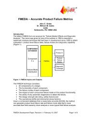
As indicated in the following figure the DVC6000 SIS receives an input signal from the logic solver<br />
system via an analog output. This input signal is a 0-20 mA, (0 - 24 VDC) or 4-20 mA signal. Only<br />
De-Energize To Trip applications have been considered in this assessment. Additionally, the<br />
DVC6000 may be operated with or without automatic shutdown enabled, but this assessment only<br />
deals with automatic shutdown disabled. The DVC6000 digital valve controller controls an actuator<br />
via output A or via output A and output B. This accounts for the different operating modes of the<br />
mechanical parts as shown in Table 1.<br />
In the single acting operating mode only output A is used. During normal operation (in De-Energize<br />
to Trip) output A is pressurized, if a shutdown is required output A is depressurized. In the double<br />
acting operating mode both output A and output B are used. During normal operation output A is<br />
greater than output B, if a shutdown is required output A is equal to or less than output B. It is<br />
assumed that the DVC6000 – actuator combination will fail safe on loss of air pressure because of<br />
the spring return action in the actuator. The actuator that is controlled by the DVC6000 on its turn<br />
controls a valve. A valve travel feedback signal is fed back to the digital valve controller but is not<br />
part of the safety critical path. The feedback signal is required in order to perform a PVST.<br />
© exida Certification SA. EFC 07-07-41 R002 V1R2 <strong>IEC</strong> <strong>61508</strong><strong>Assessment</strong>.doc, March 13, 2008<br />
Iwan van Beurden Page 8 of 19
Logic<br />
Solver<br />
DVC6000<br />
<strong>IEC</strong> <strong>61508</strong> Type B<br />
Terminal<br />
Box<br />
Printed<br />
Wiring<br />
Board<br />
Drive<br />
signal<br />
<strong>IEC</strong> <strong>61508</strong> Type A<br />
I/P<br />
Converter<br />
exida FMEDA<br />
Air supply<br />
I/P<br />
Output<br />
pressure<br />
Pneumatic<br />
Relay<br />
Figure 1 DVC6000 SIS Assembly<br />
In addition to the DVC6000 SIS external connections, Figure 1 also indicates the main parts of the<br />
digital valve controller. As described above the DVC6000 SIS can be divided into an electrical part<br />
and a mechanical part. This assessment was done on the entire product.<br />
Figure 1 also indicates the architectural constraint types of the two main parts of the DVC6000 SIS<br />
Digital Valve Controller as defined by <strong>IEC</strong> <strong>61508</strong>-2. The architectural constraint type of the MPU<br />
module assembly is Type B 1 , where the architectural constraint type of the mechanical assembly is<br />
Type A 1 . In the 0-20 mA and 0-24 VDC operating modes the MPU module assembly is not part of<br />
the safety critical path therefore the product is Type A for that operating mode. The 4-20mA<br />
operating mode DVC6000 is Type B.<br />
1 Type A device: “Non-Complex” subsystem (using discrete elements); for details see 7.4.3.1.2 of <strong>IEC</strong> <strong>61508</strong>-<br />
2./ Type B device: “Complex” component (using micro controllers or programmable logic); for details see<br />
7.4.3.1.3 of <strong>IEC</strong> <strong>61508</strong>-2.<br />
© exida Certification SA. EFC 07-07-41 R002 V1R2 <strong>IEC</strong> <strong>61508</strong><strong>Assessment</strong>.doc, March 13, 2008<br />
Iwan van Beurden Page 9 of 19<br />
Output A<br />
Output B<br />
Feedback<br />
Potentiometer<br />
Valve travel<br />
feedback<br />
Actuator<br />
Valve
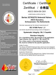
Table 1 gives an overview of the different versions that were considered in the FMEDA’s and<br />
assessment of the Fisher Controls DVC6000 SIS Digital Valve Controller - DETT.<br />
Table 1 Version overview<br />
Application <strong>Safety</strong> Function<br />
1 4-20 mA Operation, Double-Acting (Relay<br />
A), De-Energize to Trip<br />
2 4-20 mA Operation, Single-Acting (Relay<br />
C), De-Energize to Trip<br />
3 4-20 mA Operation, Single-Acting (Relay<br />
A), De-Energize to Trip<br />
4 0-20 mA or 0-24 VDC Operation, Double-<br />
Acting (Relay A), De-Energize to Trip<br />
5 0-20 mA or 0-24 VDC Operation, Single-<br />
Acting (Relay C), De-Energize to Trip<br />
6 0-20 mA or 0-24 VDC Operation, Single-<br />
Acting (Relay A), De-Energize to Trip<br />
Output A ≤ Output B (with 4 mA input signal)<br />
Output A ≤ 1 psi (with 4 mA input signal)<br />
Output A ≤ 1 psi (with 4 mA input signal)<br />
Output A ≤ Output B (with < 1 mA input<br />
signal)<br />
Output A ≤ 1 psi (with < 1 mA input signal)<br />
Output A ≤ 1 psi (with < 1 mA input signal)<br />
For the 4 – 20 mA operating mode, the fail-safe state is defined as the input signal being 4 mA. The<br />
DVC6000 SIS Digital Valve Controller is classified as a Type B 1 device for these applications<br />
according to <strong>IEC</strong> <strong>61508</strong>, having a hardware fault tolerance of 0.<br />
For the 0 – 20 mA operating mode, the fail-safe state is defined as the input signal being < 1mA.<br />
This will ensure that the electronics are no longer capable of driving the I/P module. Therefore the<br />
DVC6000 SIS Digital Valve Controller is classified as a Type A 1 device for both applications<br />
according to <strong>IEC</strong> <strong>61508</strong>, having a hardware fault tolerance of 0.<br />
© exida Certification SA. EFC 07-07-41 R002 V1R2 <strong>IEC</strong> <strong>61508</strong><strong>Assessment</strong>.doc, March 13, 2008<br />
Iwan van Beurden Page 10 of 19
3.1 Scope of Analysis<br />
The following were considered in this analysis:<br />
Product: DVC6000 SIS<br />
Models: DVC6005, DVC6010, DVC6015, DVC6020, DVC6025, DVC6030, DVC6035,<br />
DVC6010S, DVC6020S, DVC6030S<br />
Options: Remote travel sensor, Stainless Steel housing, Extreme temperature, Relay A,<br />
Relay C, Low-bleed relay A, Low-bleed relay C.<br />
Accessories: LCP100<br />
LC340 (0-24VDC applications only)<br />
© exida Certification SA. EFC 07-07-41 R002 V1R2 <strong>IEC</strong> <strong>61508</strong><strong>Assessment</strong>.doc, March 13, 2008<br />
Iwan van Beurden Page 11 of 19
4 <strong>IEC</strong> <strong>61508</strong> <strong>Functional</strong> <strong>Safety</strong> <strong>Assessment</strong><br />
The <strong>IEC</strong> <strong>61508</strong> <strong>Functional</strong> <strong>Safety</strong> <strong>Assessment</strong> was performed based on the information received<br />
from Fisher Controls International, LLC and is documented in [R2] and [R3].<br />
4.1 Methodology<br />
The full functional safety assessment includes an assessment of all fault avoidance and fault<br />
control measures during hardware and software development and demonstrates full compliance<br />
with <strong>IEC</strong> <strong>61508</strong> to the end-user. The assessment considers all requirements of <strong>IEC</strong> <strong>61508</strong>. Any<br />
requirements that have been deemed not applicable have been marked as such in the full <strong>Safety</strong><br />
Case report.<br />
As part of the <strong>IEC</strong> <strong>61508</strong> functional safety assessment the following aspects have been reviewed:<br />
• Development process, including:<br />
o <strong>Functional</strong> <strong>Safety</strong> Management, including training and competence recording, FSM<br />
planning, and configuration management<br />
o Specification process, techniques and documentation<br />
o Design process, techniques and documentation, including tools used<br />
o Validation activities, including development test procedures, test plans and reports,<br />
production test procedures and documentation<br />
o Verification activities and documentation<br />
o Modification process and documentation<br />
o Installation, operation, and maintenance requirements, including user documentation<br />
• Product design<br />
o Hardware architecture and failure behavior, documented in a FMEDA<br />
o Software architecture and failure behavior, documented in listed software analysis<br />
documents.<br />
The review of the development procedures is described in section 5.1. The review of the product<br />
design is described in section 5.2.<br />
4.2 <strong>Assessment</strong> level<br />
The DVC6000 SIS, DETT Digital Valve Controller has been assessed per <strong>IEC</strong> <strong>61508</strong> to the<br />
following levels:<br />
Systematic <strong>Safety</strong> Integrity Level: The development procedures were assessed as suitable<br />
for use in applications with a maximum <strong>Safety</strong> Integrity Level of 3 (SIL 3) according to <strong>IEC</strong><br />
<strong>61508</strong>.<br />
• Random <strong>Safety</strong> Integrity Level: PFDAVG and Architectural Constraints must be verified for<br />
each final element application up to SIL 3.<br />
© exida Certification SA. EFC 07-07-41 R002 V1R2 <strong>IEC</strong> <strong>61508</strong><strong>Assessment</strong>.doc, March 13, 2008<br />
Iwan van Beurden Page 12 of 19
5 Results of the <strong>IEC</strong> <strong>61508</strong> <strong>Functional</strong> <strong>Safety</strong> <strong>Assessment</strong><br />
exida Certification assessed the development process used by Fisher Controls International, LLC<br />
during the product development against the objectives of <strong>IEC</strong> <strong>61508</strong> parts 1, 2, and 3, in [R2] and<br />
[R3]. The development process was fully compliant with <strong>IEC</strong> <strong>61508</strong>. However, portions of the<br />
DVC6000 SIS Digital Valve Controller were developed prior to the establishment of this <strong>IEC</strong> <strong>61508</strong><br />
SIL 3 compliant development process. Consequently for the evaluation of systematic fault<br />
avoidance measures, proven in use claims were considered in addition to existing design<br />
documentation and additional documented safety analysis which showed the design integrity. The<br />
<strong>Safety</strong> Case was created with project specific design documents. Future modifications to the<br />
DVC6000 SIS Digital Valve Controller must be made per the <strong>IEC</strong> <strong>61508</strong> SIL 3 compliant<br />
development process.<br />
5.1 Lifecycle Activities and Fault Avoidance Measures<br />
Fisher Controls International, LLC has an <strong>IEC</strong> <strong>61508</strong> compliant development process as assessed<br />
during the <strong>IEC</strong> <strong>61508</strong> certification. This compliant development process is documented in [R2] and<br />
[R3]. Most of the DVC6000 SIS Digital Valve Controller functionality was developed before this <strong>IEC</strong><br />
<strong>61508</strong> compliant development process was in place, consequently proven in use arguments were<br />
considered for some of the systematic fault avoidance measures.<br />
This functional safety assessment investigated the compliance with <strong>IEC</strong> <strong>61508</strong> of the processes,<br />
procedures and techniques as implemented for the digital valve controller development. The<br />
investigation was executed using subsets of the <strong>IEC</strong> <strong>61508</strong> requirements tailored to the SIL 3 work<br />
scope of the development team. The result of the assessment can be summarized by the following<br />
observations:<br />
The audited Fisher Controls International, LLC development process complies with the<br />
relevant managerial requirements of <strong>IEC</strong> <strong>61508</strong> SIL 3.<br />
5.1.1 <strong>Functional</strong> <strong>Safety</strong> Management<br />
FSM Planning<br />
The functional safety management of any Fisher Controls International, LLC <strong>Safety</strong> Instrumented<br />
Systems Product development is governed by Engineering Standard ES 269 [D12]. For each<br />
development Fisher Controls International, LLC creates a <strong>Functional</strong> <strong>Safety</strong> Management Plan per<br />
the FSM Plan Template [D17] which defines all of the tasks that must be done to ensure functional<br />
safety as well as the person(s) responsible for each task. These processes and the procedures<br />
referenced herein fulfill the requirements of <strong>IEC</strong> <strong>61508</strong> with respect to functional safety<br />
management.<br />
Version Control<br />
All documents are under version control as documented in [D10], [R2] and [R3]. Design drawings<br />
and documents are also under version control. Fisher Controls International, LLC uses Visual<br />
Source Safe for its version control.<br />
Training, Competency recording<br />
© exida Certification SA. EFC 07-07-41 R002 V1R2 <strong>IEC</strong> <strong>61508</strong><strong>Assessment</strong>.doc, March 13, 2008<br />
Iwan van Beurden Page 13 of 19
Personnel training records are kept in accordance with <strong>IEC</strong> <strong>61508</strong> requirements as documented in<br />
[R2], [R3] and [D22]. Fisher Controls International, LLC hired exida Consulting to provide analysis,<br />
training and supplemental functional safety expertise. Fisher Controls International, LLC hired<br />
exida Certification to be the independent assessor per <strong>IEC</strong> <strong>61508</strong>.<br />
5.1.2 <strong>Safety</strong> Requirements Specification and Architecture Design<br />
As defined in [D1] and [D7], a safety requirements specification (SRS) is done for all products that<br />
must meet <strong>IEC</strong> <strong>61508</strong> requirements. The requirements specification contains a scope and safety<br />
requirements section. For the DVC6000 SIS Digital Valve Controller, the SRS [D21] and [D26],<br />
have been reviewed by exida Consulting. During the assessment, exida Certification reviewed the<br />
content of the specification for completeness per the requirements of <strong>IEC</strong> <strong>61508</strong>.<br />
Requirements are tracked throughout the development process by the creation of derived<br />
requirements, which map the requirements to the design, and by mapping requirements to<br />
appropriate validation tests in the validation test plan [D23].<br />
Requirements from <strong>IEC</strong> <strong>61508</strong>-2, Table B.1 that have been met by Fisher Controls International,<br />
LLC include project management, documentation, separation of safety requirements from nonsafety<br />
requirements, structured specification, inspection of the specification, semi-formal methods<br />
and checklists. [R21] documents more details on how each of these requirements have been met.<br />
This meets the requirements of SIL 3.<br />
5.1.3 Hardware Design<br />
Hardware design, including both electrical and mechanical design, is done according to [D1] and<br />
[D12]. The hardware design process includes component selection, detailed drawings and<br />
schematics, 3D Solid Models, safety case documents for agency justification, a failure modes and<br />
effect analysis (FMEA), a failure modes, effects and diagnostic analysis (FMEDA), a concept<br />
design review, the creating of prototypes, and hardware verification tests.<br />
Requirements from <strong>IEC</strong> <strong>61508</strong>-2, Table B.2 that have been met by Fisher Controls International,<br />
LLC include observance of guidelines and standards, project management, documentation,<br />
structured design, modularization, use of well-tried components, checklists, semi-formal methods,<br />
computer aided design tools, simulation, and inspection of the specification. This meets the<br />
requirements of SIL 3.<br />
5.1.4 Validation<br />
Validation Testing is done via a set of documented tests (see [D1] and [D23]). The validation tests<br />
are traceable to the <strong>Safety</strong> Requirements Specification [D21] and [D26] in the validation test plan<br />
[D23]. In addition to standard Test Specification Documents, third party testing may be included as<br />
part of agency approvals. As the Fisher Controls DVC6000 SIS Digital Valve Controller - DETT<br />
consists of simple electrical devices with a straightforward safety function, integration testing has<br />
been limited to verifying that all diagnostics take the appropriate action when they find a problem<br />
(See [D1] for more details on this testing).<br />
Procedures are in place for corrective actions to be taken when tests fail as documented in [R2],<br />
[R3] and [D10].<br />
© exida Certification SA. EFC 07-07-41 R002 V1R2 <strong>IEC</strong> <strong>61508</strong><strong>Assessment</strong>.doc, March 13, 2008<br />
Iwan van Beurden Page 14 of 19
Requirements from <strong>IEC</strong> <strong>61508</strong>-2, Table B.3 that have been met by Fisher Controls International,<br />
LLC include functional testing, project management, documentation, and black-box testing. Field<br />
experience and statistical testing via regression testing are not applicable. [R21] documents more<br />
details on how each of these requirements has been met. This meets the requirements of SIL 3.<br />
Requirements from <strong>IEC</strong> <strong>61508</strong>-2, Table B.5 that have been met by Fisher Controls International,<br />
LLC include functional testing and functional testing under environmental conditions, Interference<br />
surge immunity testing, fault insertion testing, project management, documentation, static analysis,<br />
dynamic analysis, and failure analysis, expanded functional testing and black-box testing. [R21]<br />
documents more details on how each of these requirements has been met. This meets SIL 3.<br />
5.1.5 Verification<br />
The development and verification activities are defined in [D1] and [D2]. Verification activities<br />
include the following: Fault Injection Testing [D45] to [D50], Code Review [D8], Checklists [D5],<br />
FMEDA [R12], [R13], [R17], and [R18], Software Criticality Analysis and HAZOP [D24], and System<br />
FMEA [R17], and [R18]. Further verification activities are documented in [D1] and [D12] for new<br />
product development projects.<br />
5.1.6 Modifications<br />
Modifications are done per the Fisher Controls International, LLC’s <strong>IEC</strong> <strong>61508</strong> SIL 3 compliant<br />
development process as documented in [D7] and [D10], and governed by [D12]. This meets the<br />
requirements of <strong>IEC</strong> <strong>61508</strong> SIL 3.<br />
5.1.7 User documentation<br />
Fisher Controls International, LLC created a <strong>Safety</strong> Manual for the DVC6000 SIS Digital Valve<br />
Controller, see [D14] and[D15]. These safety manuals were assessed by exida Certification. The<br />
final version is considered to be in compliance with the requirements of <strong>IEC</strong> <strong>61508</strong>. The document<br />
includes all required reliability data and operations, maintenance, and proof test procedures.<br />
Requirements from <strong>IEC</strong> <strong>61508</strong>-2, Table B.4 that have been met by Fisher Controls International,<br />
LLC include operation and maintenance instructions, user friendliness, maintenance friendliness,<br />
project management, documentation, limited operation possibilities, protection against operator<br />
mistakes, and operation only by skilled operators. [R21] documents more details on how each of<br />
these requirements has been met. This meets the requirements for SIL 3.<br />
© exida Certification SA. EFC 07-07-41 R002 V1R2 <strong>IEC</strong> <strong>61508</strong><strong>Assessment</strong>.doc, March 13, 2008<br />
Iwan van Beurden Page 15 of 19
5.2 Hardware <strong>Assessment</strong><br />
To evaluate the hardware design of the DVC6000 SIS Digital Valve Controller, a Failure Modes,<br />
Effects, and Diagnostic Analysis was performed by exida Consulting for each component in the<br />
system. This is documented in [R12], [R13], [R17], and [R18]. The FMEDA’s were verified using<br />
Fault Injection Testing as part of the development, see [D45] to [D50], and as part of the <strong>IEC</strong> <strong>61508</strong><br />
assessment.<br />
A Failure Modes and Effects Analysis (FMEA) is a systematic way to identify and evaluate the<br />
effects of different component failure modes, to determine what could eliminate or reduce the<br />
chance of failure, and to document the system in consideration. An FMEDA (Failure Mode Effect<br />
and Diagnostic Analysis) is an FMEA extension. It combines standard FMEA techniques with<br />
extension to identify online diagnostics techniques and the failure modes relevant to safety<br />
instrumented system design.<br />
From the FMEDA failure rates are derived for each important failure category. The detailed failure<br />
rates are listed in [R12], [R13], [R17] and [R18]. Table 2 lists these failure rates in <strong>IEC</strong> <strong>61508</strong><br />
format as reported in the FMEDA reports. The failure rates are valid for the useful life of the<br />
devices.<br />
Table 2 Failure rates according to <strong>IEC</strong> <strong>61508</strong><br />
Device λsd λsu 2 λdd λdu<br />
Fisher Controls DVC6000, DETT SIS Digital<br />
Valve Controller, 4 – 20 mA., Double or<br />
Single-Acting, Normal<br />
Fisher Controls DVC6000, DETT SIS Digital<br />
Valve Controller, 4 – 20 mA., Double or<br />
Single-Acting, w/PVST diagnostics<br />
Fisher Controls DVC6000 DETT SIS Digital<br />
Valve Controller, 0 – 20 mA., Double or<br />
Single-Acting, Normal<br />
Fisher Controls DVC6000 DETT SIS Digital<br />
Valve Controller, 0 – 20 mA., Double or<br />
Single-Acting, w/PVST diagnostics<br />
0 1183 0 144<br />
508 1004 97 47<br />
0 974 0 91<br />
543 786 62 29<br />
Tables in the FMEDA reports [R17], and [R18] lists these failure rates for the DVC6000 SIS<br />
including the optional LCP100 and LC340 under a variety of applications. The failure rates listed<br />
are valid for the useful life of the devices. Based on general field failure data a useful life period of<br />
approximately 10 years is expected for the DVC6000 SIS Digital Valve Controller. This is listed in<br />
the FMEDA report. However, when plant experience indicates a shorter useful lifetime than<br />
indicated in the FMEDA report, the number based on plant experience should be used. All other<br />
assumptions are also listed in the reports.<br />
2 It is important to realize that the “Residual Effect” failures are included in the “Safe Undetected” failure<br />
category according to <strong>IEC</strong> <strong>61508</strong>. Note that these failures on their own will not affect system reliability or<br />
safety, and should not be included in spurious trip calculations<br />
© exida Certification SA. EFC 07-07-41 R002 V1R2 <strong>IEC</strong> <strong>61508</strong><strong>Assessment</strong>.doc, March 13, 2008<br />
Iwan van Beurden Page 16 of 19
For low demand SIL 3 applications the PFDAVG value of the <strong>Safety</strong> Instrumented Function needs to<br />
be ≥ 10 -4 and < 10 -3 . The PFDAVG of all devices of a <strong>Safety</strong> Instrumented Function (SIF) must be<br />
calculated in order to determine suitability for a specific <strong>Safety</strong> Integrity Level (SIL). The <strong>Safety</strong><br />
Manual states that the application engineer should calculate the PFDAVG for each defined safety<br />
instrumented function (SIF) to verify the design of that SIF.<br />
The analysis shows that the design of the DVC6000 SIS Digital Valve Controller (including<br />
the optional LCP100 and LC340) is capable of meeting the hardware requirements of <strong>IEC</strong><br />
<strong>61508</strong> SIL 3.<br />
© exida Certification SA. EFC 07-07-41 R002 V1R2 <strong>IEC</strong> <strong>61508</strong><strong>Assessment</strong>.doc, March 13, 2008<br />
Iwan van Beurden Page 17 of 19
6 Terms and Definitions<br />
Fault tolerance Ability of a functional unit to continue to perform a required function in the<br />
presence of faults or errors (<strong>IEC</strong> <strong>61508</strong>-4, 3.6.3)<br />
FIT Failure In Time (1x10 -9 failures per hour)<br />
FMEDA Failure Mode Effect and Diagnostic Analysis<br />
HART Highway Addressable Remote Transducer<br />
HFT Hardware Fault Tolerance<br />
Low demand mode Mode, where the frequency of demands for operation made on a safetyrelated<br />
system is no greater than twice the proof test frequency.<br />
PFDAVG<br />
Average Probability of Failure on Demand<br />
PVST Partial Valve Stroke Test<br />
It is assumed that the Partial Valve Stroke Testing, when performed, is<br />
performed at least an order of magnitude more frequently than the proof<br />
test, therefore the test can be assumed an automatic diagnostic. Because of<br />
the automatic diagnostic assumption the Partial Valve Stroke Testing also<br />
has an impact on the Safe Failure Fraction.<br />
SFF Safe Failure Fraction summarizes the fraction of failures, which lead to a<br />
safe state and the fraction of failures which will be detected by diagnostic<br />
measures and lead to a defined safety action.<br />
SIF <strong>Safety</strong> Instrumented Function<br />
SIL <strong>Safety</strong> Integrity Level<br />
SIS <strong>Safety</strong> Instrumented System – Implementation of one or more <strong>Safety</strong><br />
Instrumented Functions. A SIS is composed of any combination of<br />
sensor(s), logic solver(s), and final element(s).<br />
Type A (sub)system “Non-Complex” (sub)system (using discrete elements); for details see<br />
7.4.3.1.2 of <strong>IEC</strong> <strong>61508</strong>-2<br />
Type B (sub)system “Complex” (sub)system (using micro controllers or programmable logic); for<br />
details see 7.4.3.1.3 of <strong>IEC</strong> <strong>61508</strong>-2<br />
© exida Certification SA. EFC 07-07-41 R002 V1R2 <strong>IEC</strong> <strong>61508</strong><strong>Assessment</strong>.doc, March 13, 2008<br />
Iwan van Beurden Page 18 of 19
7 Status of the document<br />
7.1 Liability<br />
exida prepares reports based on methods advocated in International standards. Failure rates are<br />
obtained from a collection of industrial databases. exida accepts no liability whatsoever for the use<br />
of these numbers or for the correctness of the standards on which the general calculation methods<br />
are based.<br />
7.2 Releases<br />
Version: V1<br />
Revision: R2<br />
Version History: V1, R2 Minor edits, March 13, 2008<br />
V1, R1: Added 0 – 20 mA; February 29, 2008<br />
V0, R1: Internal Draft; February 20, 2008<br />
Authors: Iwan van Beurden<br />
Review: V1, R1 Client<br />
V0, R1 William M. Goble<br />
Release status: Released<br />
7.3 Future Enhancements<br />
At request of client.<br />
7.4 Release Signatures<br />
William M. Goble, Principal Partner<br />
Iwan van Beurden, Director of Engineering<br />
© exida Certification SA. EFC 07-07-41 R002 V1R2 <strong>IEC</strong> <strong>61508</strong><strong>Assessment</strong>.doc, March 13, 2008<br />
Iwan van Beurden Page 19 of 19