DMP 48 AS - Dold GmbH
DMP 48 AS - Dold GmbH
DMP 48 AS - Dold GmbH

Create successful ePaper yourself
Turn your PDF publications into a flip-book with our unique Google optimized e-Paper software.
1<br />
2<br />
3<br />
����<br />
����<br />
K1 A<br />
K2 B<br />
���� ���� ����<br />
����<br />
����<br />
����<br />
4<br />
<strong>DMP</strong> <strong>48</strong> AW<br />
P<br />
<strong>DMP</strong> <strong>48</strong> <strong>AS</strong><br />
1 2<br />
P<br />
3 4<br />
����<br />
����<br />
Installation and operation of the unit<br />
DOLD <strong>GmbH</strong><br />
Blumenstraße 33<br />
70736 Fellbach<br />
Telefon 0049 (0) 711/95152-0<br />
Telefax 0049 (0) 711/95152-19<br />
info@dold-regler.de<br />
www.dold-regler.de<br />
<strong>DMP</strong> <strong>48</strong> <strong>AS</strong> - ...-2P<br />
<strong>DMP</strong> <strong>48</strong> AW - ...-2P<br />
from program version: 032E1 ... 032E9<br />
Inputs:<br />
...: P1...P5: 2xPt 100 -150...600°C<br />
L1...L2: 2xFe-CuNi 0...850°C<br />
K1...K2: 2xNiCr-Ni 0...1200°C<br />
as Two-channel controller<br />
2P: Two-point controller<br />
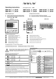
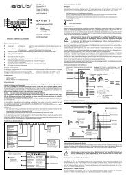
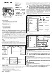
Operating and display elements<br />
���� Actual value channel 1 display in operating mode, parameter display in input mode<br />
���� Actual value channel 2 display in operating mode, parameter value in input mode<br />
���� No function<br />
���� Jump to input level and operating level, confirmation key, keying through the parameters on one level<br />
���� Reducing code value, parameter value<br />
���� Increasing code value, parameter value<br />
���� LED K 1 (1) is lit if output K 1 is active<br />
���� LED K 2 (2) is lit if output K 2 is active<br />
���� LED A (3) no function<br />
���� LED B (4) no function<br />
Safety notes<br />
Please read these notes on safety attentively and note the listed points! They concern the safety of persons and of<br />
the equipment!<br />
The unit is concepted mainly as a temperature controller. However, it can also be used for other, slow changing<br />
physical dimensions, where one measurement per second is sufficient for accurate function. The logical cohesion of<br />
the temperature controller must then be transferred to the appropriate dimensions. Substantial damage to persons<br />
and property can be caused through improper use, application, installation, configuration or operation within a plant!<br />
Important! The unit must not be used as a safety device, it serves as process controller, process control as well<br />
as process monitoring!<br />
The unit must not be installed in the EX-area! If everything with process dimensions from the EX-area and the unit is<br />
installed outside the EX-area, all supply lines of the unit, which lead into the EX-area, must be directed over safety<br />
barriers!<br />
The satisfactory and safe operation of the unit presupposes, that the unit is transported, stored and installed with due care<br />
and that it is properly fitted.<br />
This unit must be installed, configured, commissioned and parameters have been setting by qualified persons only, who are<br />
familiar with the installation, commissioning and servicing or comparative units, as well as with the installation, for which the<br />
unit is used and must have knowledge of measuring control and regulating methods.<br />
The operating personnel of the plant, in which the unit is to be used, must be instructed in its operation by qualified persons.<br />
Please note<br />
− the contents of these manual, especially the notes of installation, commissioning and adaptation of the unit to the controlling<br />
system,<br />
− the safety regulations affixed to the unit,<br />
− the respective safety regulations for the installation and the operation of electric plant,<br />
− keep these manual for later applications.<br />
The regulations mentioned in these manual are valid for all EC countries. For application in a country outside the EC, the<br />
appropriate national regulations must be observed.<br />
This unit has been manufactured and tested according to DIN EN 61010 part 1 "protection measures for electronic measuring<br />
units“, and has left our factory in a safety and operational technical satisfactory condition.<br />
Order code (identification of the unit)<br />
Input channel 1 and 2:<br />
Sensor Pt 100 P<br />
Thermocouple<br />
Fe-CuNi Type L L<br />
NiCr-Ni Type K K<br />
Measuring range:<br />
Pt 100: -50...100°C 1<br />
-50...200°C 2<br />
-50...300°C 3<br />
-50...600°C 4<br />
-150...100°C 5<br />
Fe-CuNi: 0...450°C 1<br />
0...850°C 2<br />
NiCr-Ni: 0...600°C 1<br />
0...1200°C 2<br />
Rating plate<br />
If making technical enquiries the<br />
following details are important<br />
unit type<br />
article number<br />
works number<br />
program version<br />
Mounting location of the unit<br />
unit type<br />
operating volts:<br />
switching volts:<br />
works number:<br />
inputs:<br />
outputs:<br />
program version<br />
order code:<br />
0 0 0<br />
1 1 0 0<br />
<strong>DMP</strong> <strong>48</strong> <strong>AS</strong>-...-2P XXXXXXXXXX<br />
Betriebsspannung XXX V +/-10%<br />
Schaltleistung: 500 VA bei 230 V AC<br />
Fabriknummer: XXXXXX PXXFXXHXX<br />
Eingänge:<br />
Ausgänge: Relaisausgänge<br />
Logikausgänge<br />
Programmversion: XXXXX<br />
Bestellschlüssel: XXXXX.XXXX.XXXX<br />
0<br />
article number<br />
500 VA at 230 V AC<br />
XXXXX according to order<br />
relay outputs<br />
logic outputs<br />
Operating voltage:<br />
230 V AC 1<br />
115 V AC 4<br />
<strong>48</strong> V AC 5<br />
24 V AC 7<br />
24 V DC 8<br />
Output K 1, K 2:<br />
Relay 1<br />
Logic output 2<br />
according to order<br />
according to order<br />
The mounting location must be free from vibrations. The unit must not be mounted in the proximity of motors, transformers,<br />
valves and other inductive loads. The ambient temperature at the mounting location can be 0...50°C with a rela tive humidity of<br />
≤ 75% (without dewing). Aggressive gases and vapours can quickly destroy the unit. Any fitting position is suitable.<br />
Fitting of the unit<br />
− Insert the unit from the front side into the control panel cutout<br />
− Suspending the fastener in the lateral nipple of the grip by the back of the control panel<br />
− Thereby the flat sides of the fastener must border of the housing<br />
− The fastener must be tighten against the back of the control panel symmetrical with a screwdriver<br />
− Any fitting position is suitable.<br />
Please note: Don't resort to force !<br />
Installation notes<br />
Please read the installation notes attentively and observe all listed points when installing the unit. If these notes are ignored,<br />
function interferences can occur, the required EMV guide lines are not complied with, and CE-conformity is no longer fulfilled.<br />
Ensure before connecting and commissioning of the unit, that the operating voltage and the required operating voltage ratio of<br />
the unit comply with those at the location (see rating plate and technical data). If necessary, carry out the appropriate measures.<br />
!<br />
Ensure that the control voltage and load voltage at the location is switched off and secured against switch<br />
on for the period of installing the unit. The electrical connections are to be carried out in accordance with<br />
the connection diagram and the appropriate national regulations. Use multi core cable end at wiring with<br />
flexible jumper wire. Arrange the supply lines to the unit in such a way, that they are free from tensile load<br />
under all conditions and that they are not in any possible danger of being cut-off or crushed.<br />
Shielded cables must be used for sensor leads, for thermocouples shielded compensatory leads. The sensor leads must be<br />
arranged spatially separated from the load leads and control leads (power lines).<br />
Compensatory leads for thermocouples must not be intermediately clamped with normal clamps, as otherwise additional<br />
thermocouples are created, which could falsify the measuring result!<br />
Connect the shield of the sensor lead with the unit as close as possible to the fitting board and lay the lead with a minimum of<br />
1.5 mm 2 cross-section from this point to the earthed collecting bar.<br />
Inductive loads, such as contactors, valves, motors, transformers etc., switched from the unit, as well as inductive loads<br />
installed in the same control cabinet or in the same plant, must be suppressed with unit-specific interference suppressers!<br />
The load circuits and control circuits of the unit relays must be fused against overload.<br />
These manual do not contain all notes on the regulations, standards etc., which must be observed and followed when working<br />
with the unit in connection with plants. These regulations, standards etc. must be compiled and observed by the operator of<br />
the unit, application-specific.<br />
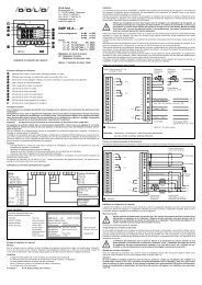
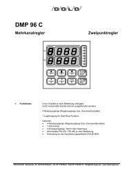
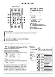
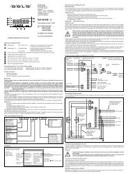
Terminal connection diagram (in dependence on version)<br />
K 1<br />
K 2<br />
coding<br />
Caution:<br />
1<br />
2<br />
3<br />
4<br />
5<br />
6<br />
7<br />
8<br />
9<br />
10<br />
11<br />
12<br />
13<br />
14<br />
15<br />
sensor<br />
Pt 100<br />
3-lead<br />
operating voltage<br />
i.e. 230 V AC, 50/60 Hz (i.e. 24 V DC)<br />
K 1 (channel 1)<br />
K 2 (channel 2)<br />
relay output<br />
sensor<br />
Pt 100<br />
2-lead<br />
(outputs K 1, K 2 dependent on version)<br />
Terminals + and terminals - do not have the same potential!<br />
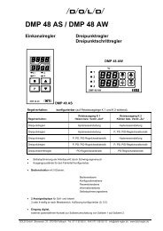
Wiring diagram (Wiring example)<br />
thermocouple<br />
+<br />
-<br />
+<br />
-<br />
(+)<br />
(-)<br />
+<br />
-<br />
+<br />
-<br />
channel 1<br />
channel 2<br />
logic output (SSR), type 0/10 V DC, max. 10 mA<br />
To enable effective discharge of interferences the shielding of the sensor leads and signal leads must be connected to earth<br />
at the side of the unit.<br />
K 1<br />
K 2<br />
coding<br />
1<br />
2<br />
3<br />
4<br />
5<br />
6<br />
7<br />
8<br />
9<br />
10<br />
11<br />
12<br />
13<br />
14<br />
15<br />
Commissioning and adaptation of the unit<br />
operating voltage<br />
fuse<br />
load<br />
fuse<br />
contactor relay,<br />
RC-protection circuit<br />
according to manu-<br />
facturers details<br />
seperate cable channel<br />
for measuring leads<br />
cable channel for<br />
voltage supply,<br />
load leads,<br />
control leads<br />
channel 1<br />
thermocouple<br />
channel 2<br />
thermocouple<br />
minimum 1,5 mm 2<br />
The unit is supplied pre-configured to an application, so by switching on some function is present. This pre-configuration is<br />
suitable for the given requirements in only a few cases, it means, the unit must be adapted to the controller system of the<br />
plant, in which it is to be used.<br />
Switch on<br />
!<br />
Check the wiring again carefully! Incorrect wiring of the unit can lead to serious damage to the unit and<br />
the plant!<br />
Ensure that the load voltage of the plant is switched off at the initial switch on of the unit, because the<br />
unit is not yet adapted to the plant and can therefore possibly cause error functions.<br />
Now switch on the operating voltage of the unit.<br />
Lead balancing or zero point correction<br />
In operation with a resistance thermometer with the two wire method, the lead resistance, as well as a safety barrier, is noticeable<br />
through a constant temperature measuring error. This temperature measuring error can be corrected on the configuration<br />
level (code 155) with parameter "Ln.1" for channel 1 and "Ln.2" for channel 2. Furthermore, the temperature difference<br />
between the temperature of the measuring point, the temperature sensors, the unit and the temperature of the process can be<br />
equalised with this parameter.<br />
!<br />
Temperature differences between measuring point and process should be kept to a minimum by selecting<br />
the measuring point! This substantially improves the controller result! When the temperature sensor<br />
is fitted improperly, overheating or under cooling can occur, and therefore, damage to personnel or<br />
material!<br />
Setting the operating nominal value<br />
The nominal value 1 for channel 1 and the nominal value 2 for channel 2 can be set on the operating level.<br />
Please note<br />
If the nominal value is taken out of adjustment during the operation of the plant, then the plant must first build-up to<br />
the new value! It means, there will be some instability in the regulation, until the actual value has set itself to the new<br />
nominal value. During operation as PID controller with relay output, it can be some time after switch on before the<br />
controller relay responds and the unit is seen to carry out its task, due to the PID typical time character!<br />
PE<br />
N<br />
L
Configuration and programming of the unit<br />
Parameter setting at the various levels<br />
P<br />
current value: +1<br />
after approx. 3 s +10<br />
after approx. 6 s +100<br />
current value: -1<br />
after approx. 3 s -10<br />
after approx. 6 s -100<br />
enter<br />
After accepting the last parameter, jump back into operating mode.<br />
If within approx. 20 seconds (timeout) no key is activated, automatic jump back to<br />
operating mode. The possibly altered value is not accepted. With the star key the<br />
timeout can be restarted (extended).<br />
If an incorrect code number is accepted for jumping to a level, you have to wait for<br />
timeout and for the jump back to operating mode before you can input a new code<br />
number (approx. 20 seconds). After this a new code input can be carried out.<br />
The operating structure<br />
In operating mode<br />
P<br />
P<br />
P<br />
press for short time<br />
Configuration of the unit<br />
CodE<br />
100<br />
Display<br />
SP.1<br />
XXX<br />
press (approx. 3 s) until: Display<br />
press (approx. 3 seconds) until:<br />
Display<br />
adjust until:<br />
Display<br />
CodE<br />
155<br />
CodE<br />
55<br />
CodE<br />
100<br />
Parameters of the configuration level<br />
(code 155)<br />
P<br />
P<br />
P<br />
Operating level<br />
(nominal value setting)<br />
Information level: for<br />
querying of current program<br />
number and sensor ID<br />
Configuration level: to configurate the<br />
controller function and the limiting values<br />
Parameter level:<br />
to adapt the unit to the controller system<br />
Display /<br />
Works setting<br />
After changing configuration or re-configuration the controller "Con"<br />
character, the appropriate parameters must be set at the<br />
parameter level (code 55) or be adapted to the controlled<br />
system.<br />
After any change of configuration or re-configuration of the<br />
setpoint range (parameters "rH.1", "rL.1", "rH.2" and "rL.2")<br />
the setpoint settings at the operating level must be checked<br />
and adapted to the setpoint range.<br />
Lead balancing or zero point correction channel 1 "Ln.1" / 0.0°C<br />
Lead balancing or zero point correction channel 2 "Ln.2" / 0.0°C<br />
Nominal value range end channel 1<br />
Adjustment range:<br />
Maximum setpoint range according to sensor-ID<br />
Nominal value range start channel 1<br />
Adjustment range:<br />
Maximum setpoint range according to sensor-ID.<br />
With configuration "rH.1" = rL.1" nominal value setting at the<br />
operating level is not possible. With configuration "rH.1" <<br />
"rL.1" switching between the set values at the operating level<br />
is possible with the buttons or .<br />
Nominal value range end channel 2<br />
Adjustment range:<br />
Maximum setpoint range according to sensor-ID<br />
Nominal value range start channel 2<br />
Adjustment range:<br />
Maximum setpoint range according to sensor-ID.<br />
With configuration "rH.2" = rL.2" nominal value setting at the<br />
operating level is not possible. With configuration "rH.2" <<br />
"rL.2" switching between the set values at the operating level<br />
is possible with the buttons or .<br />
Configuration control output or limit comparator K 1,<br />
channel 1<br />
00: output no function<br />
01: cooling controller with hysteresis setting to higher temp.<br />
02: cooling controller with PID-character<br />
03: limit comparator closed in goodband<br />
04: heating controller with hysteresis setting to lower temp.<br />
05: heating controller with PID-character<br />
06: limit comparator open in goodband<br />
Configuration control output or limit comparator K 2,<br />
channel 2<br />
00: output no function<br />
01: cooling controller with hysteresis setting to higher temp.<br />
02: cooling controller with PID-character<br />
03: limit comparator closed in goodband<br />
04: heating controller with hysteresis setting to lower temp.<br />
05: heating controller with PID-character<br />
06: limit comparator open in goodband<br />
Error allocation output K 1, K 2<br />
output K 1<br />
output K 2<br />
on: output active in event of an error<br />
OFF: output inactive in event of an error<br />
!<br />
Display resolution<br />
00: resolution 0.1°C<br />
01: resolution 1°C<br />
"rH.1" /<br />
maximum<br />
setpoint range<br />
"rL.1" /<br />
0.0°C<br />
"rH.2" /<br />
maximum<br />
setpoint range<br />
"rL.2" /<br />
0.0°C<br />
"Co.1" /<br />
05<br />
"Co.2" /<br />
05<br />
"Fd.1" / OFF<br />
"Fd.2" / OFF<br />
Incorrect error allocation at the outputs can, in the event of<br />
an error, cause substantial damage to persons and property !<br />
Parameters of the parameter level<br />
(code 55)<br />
In dependence of configuration only those parameters become<br />
accessible, which are required for the appertaining function.<br />
K 1 Output with hysteresis, channel 1 ("Co.1" = 01, 04)<br />
hysteresis<br />
K 1 Output with PID-character, channel 1 ("Co.1" = 02, 05)<br />
proportional band (Pb = 0.1...200% refer to maximum setpoint<br />
range by sensor-ID)<br />
integral time (0...999 s, setting 0 = portion 0)<br />
derivative time (0...500 s, setting 0 = portion 0)<br />
cycle time (1...200 s)<br />
K 1 Limiting comparator, channel 1 ("Co.1" = 03, 06)<br />
symmetric spreading (hysteresis 0.5 fix)<br />
K 1 Output, channel 1 ("Co.1" = 00)<br />
Output K 1 no function<br />
"rES" /<br />
00<br />
Display /<br />
Works setting<br />
"PAr"<br />
"HY.1" /<br />
1.0°C<br />
"Pb.1" / 5.0%<br />
"ti.1" / 250 s<br />
"td.1" / 50 s<br />
"CY.1" / 30 s<br />
"bd.1" /<br />
5.0°C<br />
"noP"<br />
Parameters of the parameter level<br />
(code 55)<br />
K 2 Output with hysteresis, channel 2 ("Co.2" = 01, 04)<br />
hysteresis<br />
K 2 Output with PID-character, channel 2 ("Co.2" = 02, 05)<br />
proportional band (Pb = 0.1...200% refer to maximum setpoint<br />
range by sensor-ID)<br />
integral time (0...999 s, setting 0 = portion 0)<br />
derivative time (0...500 s, setting 0 = portion 0)<br />
cycle time (1...200 s)<br />
K 2 Limiting comparator, channel 2 ("Co.2" = 03, 06)<br />
symmetric spreading (hysteresis 0.5°C fix)<br />
K 2 Output, channel 2 ("Co.2" = 00)<br />
Output K 2 no function<br />
Nominal value setting (operating level)<br />
Nominal value 1, channel 1<br />
Adjustment range: "rL.1"..."rH.1"<br />
Nominal value 2, channel 2<br />
Adjustment range: "rL.2"..."rH.2"<br />
Display /<br />
Works setting<br />
"HY.2" /<br />
1.0°C<br />
"Pb.2" / 5.0%<br />
"ti.2" / 250 s<br />
"td.2" / 50 s<br />
"CY.2" / 30 s<br />
"bd.2" /<br />
5.0°C<br />
"noP"<br />
Display /<br />
Works setting<br />
"SP.1" /<br />
0.0°C<br />
"SP.2" /<br />
0.0°C<br />
Information level Display<br />
Querying of current program number and sensor-ID in the<br />
information level.<br />
"inF"<br />
Current program number "Pnr"<br />
Sensor-ID as in table "SEn"<br />
Sensor-ID<br />
Sensor-<br />
ID<br />
ID by<br />
ordering key<br />
Sensor<br />
(channel 1 and 2)<br />
Max. display<br />
range<br />
Max. setpoint<br />
range<br />
P 1 P 1 Pt 100 -69...149°C -50...100°C<br />
P 2 P 2 Pt 100 -69...249°C -50...200°C<br />
P 3 P 3 Pt 100 -69...349°C -50...300°C<br />
P 4 P 4 Pt 100 -69...699°C -50...600°C<br />
P 5 P 5 Pt 100 -169...149°C -150...100°C<br />
tL1 L 1 Fe-CuNi Type L -24...499°C 0...450°C<br />
tL2 L 2 Fe-CuNi Type L -24...899°C 0...850°C<br />
tn1 K 1 Ni Cr-Ni Type K -24...649°C 0...600°C<br />
tn2 K 2 Ni Cr-Ni Type K -24...1299°C 0...1200°C<br />
Adapting the PID controller to the controlled system - Rule of thumb for<br />
adjusting the controller<br />
Ascertainment of the characteristic data in a closed-loop control circuit<br />
A controlling system with unknown PID parameters have to be tuned by an oscillation<br />
test in a closed-loop control circuit.<br />
The following characteristic data are necessary to calculate the PID parameters.<br />
− Amplitude of oscillation ΔT<br />
− Duration of period of oscillation Tp.<br />
These characteristic data can be carried out by observation of the actual value, or<br />
by recording the controller curve with a measuring recorder.<br />
Condition<br />
Setting the parameter at the parameter level (code 55):<br />
Proportional band Pb (parameter "Pb.X") 0.1%<br />
Integral time Ti (parameter "ti.X") 0 s<br />
Derivative time Td (parameter "td.X") 0 s<br />
Cycle time Cy (parameter "Cy.X") 1 s<br />
T<br />
(°C)<br />
Oscillation test<br />
Tp<br />
Calculating the PID return parameter by the ascertained values<br />
Tp = Duration of period of oscillation<br />
ΔT = Amplitude of oscillation<br />
ΔT = T max. - T min. (°C)<br />
(Setpoint range according to sensor-ID)<br />
Pb = 3�ΔT (°C) �100%<br />
Setpoint range (°C)<br />
Ti = 0,65·Tp<br />
Td = 0,16·Tp<br />
Cycle time Cy = Td<br />
4<br />
T<br />
T max.<br />
Nominal value<br />
T min.<br />
Now the calculated PID return parameter can be set on the parameter level<br />
(code 55).<br />
Please note : Lifetime of the relays<br />
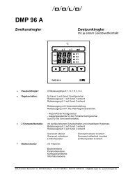
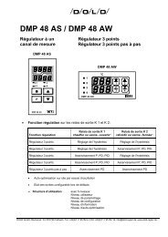
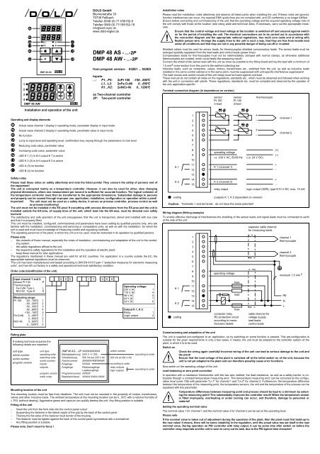
Inspection of the return parameters<br />
The diagrams show possible incorrect settings, and give hints for their correction.<br />
X<br />
(°C)<br />
W<br />
X<br />
(°C)<br />
W<br />
X<br />
(°C)<br />
W<br />
Pb too small<br />
regulation oscillates<br />
Ti too small<br />
Td too large<br />
t<br />
t<br />
t<br />
X<br />
(°C)<br />
W<br />
X<br />
(°C)<br />
W<br />
X<br />
(°C)<br />
W<br />
optimum setting<br />
optimum setting<br />
optimum setting<br />
Incorrect settings of the return parameters<br />
t<br />
t<br />
t<br />
X<br />
(°C)<br />
W<br />
X<br />
(°C)<br />
W<br />
X<br />
(°C)<br />
W<br />
Ti too large<br />
Td too small<br />
t / s<br />
Pb too large<br />
slow approach and<br />
poor regulation<br />
t<br />
t<br />
t<br />
Caution!<br />
!<br />
Lifetime of the relays<br />
Period per<br />
switching cycle<br />
During oscillation test extreme conditions can occur in the<br />
plant. The oscillation test have to be monitored continuously.<br />
Lifetime of the relays!<br />
Period, after which the 10 6 switching cycles are<br />
reached (8 hour/day operation with 500 VA load)<br />
2 minutes approx. 11.4 years<br />
60 seconds approx. 5.7 years<br />
30 seconds approx. 2.8 years<br />
This table is not valid for SSR relays (solid state relays)<br />
Error messages<br />
Display Error (channel 1 or channel 2)<br />
Er.1 Pt 100: falling below range, exceeding range,<br />
sensor faulty (interruption or short circuit),<br />
thermocouple: falling below range, exceeding range,<br />
sensor faulty (interruption),<br />
sensor lead (balancing lead) cross-polarity,<br />
ambient temperature of the unit > 70°C or < -10°C<br />
Er.9 System error (switch unit off/on)<br />
Technical data<br />
Inputs (channel 1 and channel 2)<br />
Pt 100 two-wire lead, three-wire lead range according to sensor-ID<br />
two-wire lead switching: circuit balancing maximum 9 Ω<br />
three-wire lead switching: wire resistance compensation maximum 50 Ω each lead<br />
Thermocouple type and range according to sensor-ID<br />
Common data<br />
measuring cycle 1 s<br />
resolution ≥ 12 Bit<br />
Outputs<br />
2 Relay outputs K 1 and K 2, make contact<br />
contact load ≤ 250 V AC, ≤ 8 A resistive load, type 500 VA with 10 6 switching cycles<br />
or Logic outputs for SSR instead of K 1 or K 2 (type 0/10 V DC, max. 10 mA)<br />
Energy supply<br />
Operating voltage 230 V AC ± 10%, <strong>48</strong>...62 Hz<br />
Rate of power input ≤ 4 VA<br />
Special voltages: 115 V AC, <strong>48</strong> V AC, 24 V AC, 24 V DC, other special voltages<br />
ask the producer, protection: the unit has a built-in thermal protection<br />
Climatic requirements<br />
according to 75% relative humidity without dewing<br />
working temperature range 0...+50°C<br />
storage temperature range -30...+70°C<br />
Electric safety<br />
according to DIN EN 61 010<br />
excess voltage category III<br />
degree of contamination 2 according to DIN EN 60 335<br />
protection class II<br />
isolation group C according to DIN VDE 0110 b<br />
type of protection DIN EN 60 529<br />
front panel IP 50<br />
(optionally: IP 54 with the proper mounting and a suitable sealing ring)<br />
housing IP 30<br />
connections IP 20<br />
Terminal connections: screwed socket stripsnominal cross section 2.5 mm 2<br />
Housing, mounting<br />
Pull-out housing for mounting control panel as per DIN 43 700 with a B fastener as<br />
per DIN 43 835 (M 4 screw clamp)<br />
Material: PPO, glass-fiber reinforced (Noryl GFN2SE1), self-extinguishing, nondripping,<br />
fire protection class UL 94 V1<br />
Front panel dimensions <strong>48</strong> + 96 / 96 x <strong>48</strong> mm<br />
Control panel cutout 92 +0.8 x 45 +0.6 mm<br />
Recess depth 125 mm<br />
CE - conformity<br />
Interference emission trade EN 50 081-1<br />
industry EN 50 081-2<br />
Interference immunity trade EN 50 082-1<br />
industry EN 50 082-2<br />
IEC 801-2<br />
IEC 801-3<br />
IEC 801-4<br />
� Subject to technical and functional change.<br />
e1e032q.doc Date: 08.08.2006