netLINK NL 51N-DPL - Hilscher
netLINK NL 51N-DPL - Hilscher
netLINK NL 51N-DPL - Hilscher

Create successful ePaper yourself
Turn your PDF publications into a flip-book with our unique Google optimized e-Paper software.
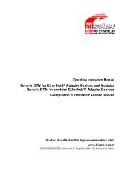
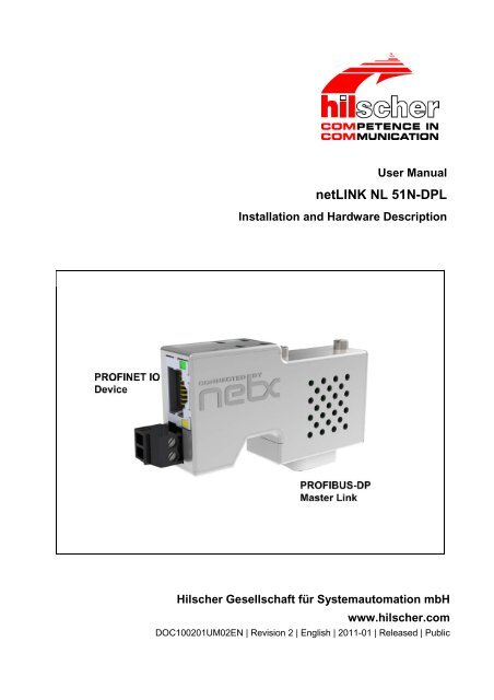
User Manual<br />
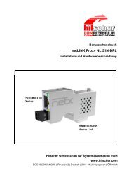
<strong>netLINK</strong> <strong>NL</strong> <strong>51N</strong>-<strong>DPL</strong><br />
Installation and Hardware Description<br />
<strong>Hilscher</strong> Gesellschaft für Systemautomation mbH<br />
www.hilscher.com<br />
DOC100201UM02EN | Revision 2 | English | 2011-01 | Released | Public
Introduction 2/32<br />
Table of Contents<br />
1 INTRODUCTION.........................................................................................................4<br />
1.1 About the User Manual............................................................................................. 4<br />
1.1.1 List of Revisions ...................................................................................................4<br />
1.1.2 Reference to Hardware ........................................................................................5<br />
1.1.3 Reference to Firmware.........................................................................................5<br />
1.1.4 Reference to SyCon Software..............................................................................5<br />
1.1.5 Conventions in this Manual ..................................................................................5<br />
1.2 Contents of the Product DVD ................................................................................... 6<br />
1.2.1 Directory Structure of the DVD.............................................................................6<br />
1.2.2 Documentation Overview .....................................................................................7<br />
1.3 Legal Notes.............................................................................................................. 8<br />
1.3.1 Copyright ..............................................................................................................8<br />
1.3.2 Important Notes ....................................................................................................8<br />
1.3.3 Exclusion of Liability .............................................................................................9<br />
1.3.4 Warranty ...............................................................................................................9<br />
1.3.5 Export Regulations .............................................................................................10<br />
1.3.6 Registered Trademarks......................................................................................10<br />
1.4 Licenses................................................................................................................. 10<br />
2 SAFETY ....................................................................................................................11<br />
2.1 General Note.......................................................................................................... 11<br />
2.2 Intended Use.......................................................................................................... 11<br />
2.3 Personnel Qualification .......................................................................................... 11<br />
2.4 Commitment to read and understand the Manual................................................... 11<br />
2.5 References Safety.................................................................................................. 11<br />
2.6 Labeling of Safety Instructions ............................................................................... 12<br />
2.7 Safety Instructions.................................................................................................. 13<br />
2.7.1 Damage by interrupting the Process ..................................................................13<br />
2.8 Property Damage Messages.................................................................................. 14<br />
2.8.1 Electrical Supply Voltage....................................................................................14<br />
2.8.2 Electrostatically sensitive Devices......................................................................14<br />
3 DESCRIPTION AND REQUIREMENTS....................................................................15<br />
3.1 Description............................................................................................................. 15<br />
3.2 Requirements for Operation of the <strong>NL</strong> <strong>51N</strong>-<strong>DPL</strong> .................................................... 16<br />
3.3 Configuration Requirements................................................................................... 16<br />
4 DEVICE DRAWINGS AND CONNECTIONS ............................................................17<br />
4.1 Dimensioned Drawing ............................................................................................ 17<br />
4.2 Labels .................................................................................................................... 17<br />
<strong>netLINK</strong> <strong>NL</strong> <strong>51N</strong>-<strong>DPL</strong> | Installation and Hardware Description<br />
DOC100201UM02EN | Revision 2 | English | 2011-01 | Released | Public © <strong>Hilscher</strong>, 2010-2011
Introduction 3/32<br />
4.3 Connections ........................................................................................................... 18<br />
4.3.1 X1 Power Supply ................................................................................................18<br />
4.3.2 X2 Ethernet Interface..........................................................................................18<br />
4.3.3 X3 PROFIBUS Interface.....................................................................................19<br />
4.4 Schematic Diagram - Galvanic Isolation................................................................. 20<br />
5 COMMISSIONING ....................................................................................................21<br />
5.1 Warnings of Damage to Property ........................................................................... 21<br />
5.1.1 Electrostatically sensitive Devices......................................................................21<br />
5.2 Mounting Instructions ............................................................................................. 21<br />
5.3 Ethernet Connection .............................................................................................. 21<br />
5.4 Configuration.......................................................................................................... 22<br />
5.4.1 Setting up the IP Address...................................................................................22<br />
5.4.2 Establishing Communication SYCON.net – <strong>netLINK</strong> <strong>51N</strong>-<strong>DPL</strong> .........................22<br />
5.4.3 Importing the GSD file ........................................................................................22<br />
5.4.4 PROFIBUS Network Scan..................................................................................23<br />
5.4.5 Configuration download......................................................................................23<br />
5.4.6 Exporting the GSDML file...................................................................................23<br />
5.4.7 Configuring PROFINET Station Name/Multiple <strong>netLINK</strong>s..................................24<br />
5.5 Start-up Behavior ................................................................................................... 25<br />
5.6 Decommissioning................................................................................................... 25<br />
6 TROUBLESHOOTING ..............................................................................................26<br />
7 LEDS.........................................................................................................................27<br />
8 TECHNICAL DATA ...................................................................................................28<br />
8.1 Device.................................................................................................................... 28<br />
8.2 Protocols................................................................................................................ 29<br />
8.2.1 PROFINET IO Device.........................................................................................29<br />
8.2.2 PROFIBUS-DP Master .......................................................................................30<br />
9 LISTS ........................................................................................................................31<br />
9.1 List of Figures ........................................................................................................ 31<br />
9.2 List of Tables.......................................................................................................... 31<br />
10 CONTACTS...............................................................................................................32<br />
<strong>netLINK</strong> <strong>NL</strong> <strong>51N</strong>-<strong>DPL</strong> | Installation and Hardware Description<br />
DOC100201UM02EN | Revision 2 | English | 2011-01 | Released | Public © <strong>Hilscher</strong>, 2010-2011
Introduction 4/32<br />
1 Introduction<br />
1.1 About the User Manual<br />
1.1.1 List of Revisions<br />
This user manual contains a description for the <strong>netLINK</strong> <strong>NL</strong> <strong>51N</strong>-<strong>DPL</strong> device<br />
using the netX 50 communication controller.<br />
This user manual contains information for commissioning and use of the<br />
device.<br />
Index Date Chapter Revisions<br />
1 2010-08-13 all Created<br />
2 2011-01-31 4.1 Dimensions<br />
8.1 Dimensions, weight, power supply voltage<br />
Table 1: List of Revisions<br />
<strong>netLINK</strong> <strong>NL</strong> <strong>51N</strong>-<strong>DPL</strong> | Installation and Hardware Description<br />
DOC100201UM02EN | Revision 2 | English | 2011-01 | Released | Public © <strong>Hilscher</strong>, 2010-2011
Introduction 5/32<br />
1.1.2 Reference to Hardware<br />
Device Revision<br />
<strong>NL</strong> <strong>51N</strong>-<strong>DPL</strong> 2<br />
Table 2: Reference to Hardware<br />
1.1.3 Reference to Firmware<br />
Firmware Revision<br />
L<strong>51N</strong>PSDL.NXF 1.0.11.0<br />
Table 3: Reference to Firmware<br />
1.1.4 Reference to SyCon Software<br />
Software Revision<br />
SyCon.net 1.300.x.x or higher<br />
Table 4: Reference to Software<br />
1.1.5 Conventions in this Manual<br />
Operation instructions, a result of an operation step or notes are marked as<br />
follows:<br />
Operation Instructions:<br />
� <br />
Or<br />
1. <br />
2. <br />
Results:<br />
� <br />
Notes:<br />
Important: <br />
Note: <br />
<br />
<strong>netLINK</strong> <strong>NL</strong> <strong>51N</strong>-<strong>DPL</strong> | Installation and Hardware Description<br />
DOC100201UM02EN | Revision 2 | English | 2011-01 | Released | Public © <strong>Hilscher</strong>, 2010-2011
Introduction 6/32<br />
1.2 Contents of the Product DVD<br />
The product DVD for the <strong>netLINK</strong> <strong>NL</strong> <strong>51N</strong>-<strong>DPL</strong> contains:<br />
• Setup program for the configuration and diagnostics tool SYCON.net<br />
and Ethernet Device Setup Tool<br />
• Documentation<br />
• Firmware<br />
• Device Description Files (GSD, GSDML, EDS, ...)<br />
1.2.1 Directory Structure of the DVD<br />
All manuals on this DVD are delivered in the Adobe Acrobat ® Reader format<br />
(PDF).<br />
Directory Name Description<br />
Adobe Flash Player Adobe Flash Player installation program.<br />
Documentation Documentation in the Acrobat ® Reader Format (PDF).<br />
Driver not needed for <strong>NL</strong> <strong>51N</strong>-<strong>DPL</strong><br />
EDS not needed for <strong>NL</strong> <strong>51N</strong>-<strong>DPL</strong><br />
Examples not needed for <strong>NL</strong> <strong>51N</strong>-<strong>DPL</strong><br />
Firmware Loadable Firmware.<br />
fscommand Files, used for installation.<br />
Presentations Product Presentations in PowerPoint pps format.<br />
Software Configuration and diagnostic program SYCON.net.<br />
Tools not needed for <strong>NL</strong> <strong>51N</strong>-<strong>DPL</strong><br />
Video-Audio Tutorials<br />
Table 5: Directory Structure of the DVD<br />
Video Tutorial/Podcast in AVI format of commissioning and configuration<br />
procedures. Contains a video in the folder “<strong>NL</strong> <strong>51N</strong>-<strong>DPL</strong> –<br />
<strong>netLINK</strong> PROXY” illustrating a typical <strong>netLINK</strong> <strong>51N</strong>-<strong>DPL</strong> commissioning<br />
procedure.<br />
<strong>netLINK</strong> <strong>NL</strong> <strong>51N</strong>-<strong>DPL</strong> | Installation and Hardware Description<br />
DOC100201UM02EN | Revision 2 | English | 2011-01 | Released | Public © <strong>Hilscher</strong>, 2010-2011
Introduction 7/32<br />
1.2.2 Documentation Overview<br />
The following documentation overview gives information, for which items<br />
you can find further information and in which manual.<br />
Documentation for Users<br />
Note: Further information:<br />
All manuals listed in the overview below can be found in the Documentation<br />
directory on the delivered DVD in Adobe Acrobat ® Reader format<br />
(PDF).<br />
Manual Contents Document name<br />
User Manual<br />
<strong>netLINK</strong> <strong>NL</strong> <strong>51N</strong>-<strong>DPL</strong><br />
Operating Instruction<br />
Manual<br />
netGateway<br />
Operating Instruction<br />
Manual<br />
SYCON.net<br />
Operating Instruction<br />
Manual<br />
netDevice and net-<br />
Project<br />
Operating Instruction<br />
Manual<br />
Ethernet Device Configuration<br />
Installation and Hardware description of<br />
the <strong>netLINK</strong> <strong>NL</strong> <strong>51N</strong>-<strong>DPL</strong><br />
Description of the configuration software<br />
SYCON.net for configuration of the<br />
<strong>NL</strong> <strong>51N</strong>-<strong>DPL</strong> device: netGateway DTM for<br />
netTAP, netBRICK and <strong>netLINK</strong>; Configuration<br />
of Gateway- and Proxy Devices<br />
Description of the configuration software<br />
SYCON.net<br />
Configuration of field devices of various<br />
manufacturers<br />
Assignment of IP-Address for the net-<br />
LINK <strong>NL</strong> <strong>51N</strong>-<strong>DPL</strong><br />
<strong>netLINK</strong> <strong>NL</strong> <strong>51N</strong>-<strong>DPL</strong> UM xx EN.pdf<br />
(this manual)<br />
netGateway_DTM_en.pdf<br />
Table 6: Documentations for <strong>netLINK</strong> <strong>NL</strong> <strong>51N</strong>-<strong>DPL</strong> for users<br />
SYCONnet_netFrame_en.pdf<br />
SYCONnet_netDevice_en.pdf<br />
Ethernet Device Configuration OI<br />
xx EN.pdf<br />
<strong>netLINK</strong> <strong>NL</strong> <strong>51N</strong>-<strong>DPL</strong> | Installation and Hardware Description<br />
DOC100201UM02EN | Revision 2 | English | 2011-01 | Released | Public © <strong>Hilscher</strong>, 2010-2011
Introduction 8/32<br />
1.3 Legal Notes<br />
1.3.1 Copyright<br />
1.3.2 Important Notes<br />
© <strong>Hilscher</strong>, 2010-2011, <strong>Hilscher</strong> Gesellschaft für Systemautomation mbH<br />
All rights reserved.<br />
The images, photographs and texts in the accompanying material (user<br />
manual, accompanying texts, documentation, etc.) are protected by German<br />
and international copyright law as well as international trade and protection<br />
provisions. You are not authorized to duplicate these in whole or in<br />
part using technical or mechanical methods (printing, photocopying or other<br />
methods), to manipulate or transfer using electronic systems without prior<br />
written consent. You are not permitted to make changes to copyright notices,<br />
markings, trademarks or ownership declarations. The included diagrams<br />
do not take the patent situation into account. The company names<br />
and product descriptions included in this document may be trademarks or<br />
brands of the respective owners and may be trademarked or patented. Any<br />
form of further use requires the explicit consent of the respective rights<br />
owner.<br />
The user manual, accompanying texts and the documentation were created<br />
for the use of the products by qualified experts, however, errors cannot be<br />
ruled out. For this reason, no guarantee can be made and neither juristic<br />
responsibility for erroneous information nor any liability can be assumed.<br />
Descriptions, accompanying texts and documentation included in the user<br />
manual do not present a guarantee nor any information about proper use<br />
as stipulated in the contract or a warranted feature. It cannot be ruled out<br />
that the user manual, the accompanying texts and the documentation do<br />
not correspond exactly to the described features, standards or other data of<br />
the delivered product. No warranty or guarantee regarding the correctness<br />
or accuracy of the information is assumed.<br />
We reserve the right to change our products and their specification as well<br />
as related user manuals, accompanying texts and documentation at all<br />
times and without advance notice, without obligation to report the change.<br />
Changes will be included in future manuals and do not constitute any obligations.<br />
There is no entitlement to revisions of delivered documents. The<br />
manual delivered with the product applies.<br />
<strong>Hilscher</strong> Gesellschaft für Systemautomation mbH is not liable under any<br />
circumstances for direct, indirect, incidental or follow-on damage or loss of<br />
earnings resulting from the use of the information contained in this publication.<br />
<strong>netLINK</strong> <strong>NL</strong> <strong>51N</strong>-<strong>DPL</strong> | Installation and Hardware Description<br />
DOC100201UM02EN | Revision 2 | English | 2011-01 | Released | Public © <strong>Hilscher</strong>, 2010-2011
Introduction 9/32<br />
1.3.3 Exclusion of Liability<br />
1.3.4 Warranty<br />
The software was produced and tested with utmost care by <strong>Hilscher</strong> Gesellschaft<br />
für Systemautomation mbH and is made available as is. No warranty<br />
can be assumed for the performance and flawlessness of the software<br />
for all usage conditions and cases and for the results produced when<br />
utilized by the user. Liability for any damages that may result from the use<br />
of the hardware or software or related documents, is limited to cases of intent<br />
or grossly negligent violation of significant contractual obligations. Indemnity<br />
claims for the violation of significant contractual obligations are limited<br />
to damages that are foreseeable and typical for this type of contract.<br />
It is strictly prohibited to use the software in the following areas:<br />
• for military purposes or in weapon systems;<br />
• for the design, construction, maintenance or operation of nuclear facilities;<br />
• in air traffic control systems, air traffic or air traffic communication systems;<br />
• in life support systems;<br />
• in systems in which failures in the software could lead to personal injury<br />
or injuries leading to death.<br />
We inform you that the software was not developed for use in dangerous<br />
environments requiring fail-proof control mechanisms. Use of the software<br />
in such an environment occurs at your own risk. No liability is assumed for<br />
damages or losses due to unauthorized use.<br />
Although the hardware and software was developed with utmost care and<br />
tested intensively, <strong>Hilscher</strong> Gesellschaft für Systemautomation mbH does<br />
not guarantee its suitability for any purpose not confirmed in writing. It cannot<br />
be guaranteed that the hardware and software will meet your requirements,<br />
that the use of the software operates without interruption and that<br />
the software is free of errors. No guarantee is made regarding infringements,<br />
violations of patents, rights of ownership or the freedom from interference<br />
by third parties. No additional guarantees or assurances are made<br />
regarding marketability, freedom of defect of title, integration or usability for<br />
certain purposes unless they are required in accordance with the law and<br />
cannot be limited. Warranty claims are limited to the right to claim rectification.<br />
<strong>netLINK</strong> <strong>NL</strong> <strong>51N</strong>-<strong>DPL</strong> | Installation and Hardware Description<br />
DOC100201UM02EN | Revision 2 | English | 2011-01 | Released | Public © <strong>Hilscher</strong>, 2010-2011
Introduction 10/32<br />
1.3.5 Export Regulations<br />
1.3.6 Registered Trademarks<br />
1.4 Licenses<br />
The delivered product (including the technical data) is subject to export or<br />
import laws as well as the associated regulations of different counters, in<br />
particular those of Germany and the USA. The software may not be exported<br />
to countries where this is prohibited by the United States Export<br />
Administration Act and its additional provisions. You are obligated to comply<br />
with the regulations at your personal responsibility. We wish to inform<br />
you that you may require permission from state authorities to export, reexport<br />
or import the product.<br />
Windows ® 2000 / Windows ® XP are registered trademarks of Microsoft<br />
Corporation.<br />
Adobe-Acrobat ® is a registered trademark of the Adobe Systems Incorporated.<br />
S7, S7-300, S7-400 and MPI are registered trademarks of Siemens AG,<br />
Berlin and Munich.<br />
PROFIBUS and PROFINET are registered trademarks of PROFIBUS International,<br />
Karlsruhe.<br />
All other mentioned trademarks are property of their respective legal owners.<br />
The <strong>NL</strong> <strong>51N</strong>-<strong>DPL</strong> device contains a license for the PROFIBUS-DP Master<br />
Link allowing the communication to a single PROFIBUS-DP Slave device.<br />
<strong>netLINK</strong> <strong>NL</strong> <strong>51N</strong>-<strong>DPL</strong> | Installation and Hardware Description<br />
DOC100201UM02EN | Revision 2 | English | 2011-01 | Released | Public © <strong>Hilscher</strong>, 2010-2011
Safety 11/32<br />
2 Safety<br />
2.1 General Note<br />
2.2 Intended Use<br />
The user manual, the accompanying texts and the documentation are written<br />
for the use of the products by educated personnel. When using the<br />
products, all safety instructions and all valid legal regulations have to be<br />
obeyed. Technical knowledge is presumed. The user has to assure that all<br />
legal regulations are obeyed.<br />
The <strong>netLINK</strong> <strong>NL</strong> <strong>51N</strong>-<strong>DPL</strong> may only be used as a part of a communication<br />
system as described in this manual.<br />
The device may not be opened or be used when the housing has been removed.<br />
2.3 Personnel Qualification<br />
The <strong>netLINK</strong> <strong>NL</strong> <strong>51N</strong>-<strong>DPL</strong> is used as a part of a system which must fulfill<br />
safety and accident precaution regulations depending on the respective<br />
conditions of use. The user of the system is exclusively responsible for the<br />
fulfillment of those regulations.<br />
Therefore the system to which the <strong>netLINK</strong> <strong>NL</strong> <strong>51N</strong>-<strong>DPL</strong> belongs may only<br />
be used by personnel who has been informed and educated about all relevant<br />
regulations.<br />
2.4 Commitment to read and understand the Manual<br />
2.5 References Safety<br />
Important! Read and understand all instructions in this manual before installation<br />
or use of your device to avoid injury.<br />
[1] EN 61340-5-1 and EN 61340-5-2 as well as IEC 61340-5-1 and IEC 61340-5-2<br />
<strong>netLINK</strong> <strong>NL</strong> <strong>51N</strong>-<strong>DPL</strong> | Installation and Hardware Description<br />
DOC100201UM02EN | Revision 2 | English | 2011-01 | Released | Public © <strong>Hilscher</strong>, 2010-2011
Safety 12/32<br />
2.6 Labeling of Safety Instructions<br />
The safety instructions are pinpointed particularly. The instructions are<br />
highlighted with a specific safety symbol, a warning triangle and a signal<br />
word according to the degree of endangerment. Inside the note the danger<br />
is exactly named. Instructions to a property damage message do not contain<br />
a warning triangle.<br />
Symbol Symbol<br />
(USA)<br />
Sort of Warning or Principle<br />
Warning of Personal Injury<br />
Warning of damages by electrostatic discharge<br />
Principle: Mandatory read Manual<br />
Table 7: Safety Symbols and Sort of Warning or Principle<br />
Signal Word Meaning Signal Word (USA) Meaning (USA)<br />
DANGER Indicates a direct hazard with high<br />
risk, which will have as consequence<br />
death or grievous bodily<br />
harm if it isn't avoided.<br />
WARNING Indicates a possible hazard with<br />
medium risk, which will have as<br />
consequence death or (grievous)<br />
bodily harm if it isn't avoided.<br />
CAUTION Indicates a minor hazard with medium<br />
risk, which could have as<br />
consequence simple battery if it<br />
isn't avoided.<br />
NOTICE Indicates a Property Damage<br />
Message.<br />
Note Indicates an important note in the<br />
manual.<br />
Table 8: Signal Words<br />
Indicates a Hazardous<br />
Situation Which, if not<br />
Avoided, will Result in<br />
Death or Serious Injury.<br />
Indicates a Hazardous<br />
Situation Which, if not<br />
Avoided, could Result in<br />
Death or Serious Injury.<br />
Indicates a Hazardous<br />
Situation Which, if not<br />
Avoided, may Result in<br />
Minor or Moderate Injury.<br />
Indicates a Property<br />
Damage Message.<br />
Note Indicates an Important<br />
Note in the Manual.<br />
In this document the safety instructions and property damage messages<br />
are designed according both to the international used safety conventions as<br />
well as to the ANSI standard, refer to reference safety [1].<br />
<strong>netLINK</strong> <strong>NL</strong> <strong>51N</strong>-<strong>DPL</strong> | Installation and Hardware Description<br />
DOC100201UM02EN | Revision 2 | English | 2011-01 | Released | Public © <strong>Hilscher</strong>, 2010-2011
Safety 13/32<br />
2.7 Safety Instructions<br />
To ensure your own personal safety and to avoid personal injury, you necessarily<br />
must read, understand and follow the following and all other safety<br />
instructions in this guide.<br />
2.7.1 Damage by interrupting the Process<br />
WARNING!<br />
Damage can result process dependant, if the data communication in a process<br />
plant is interrupted. Clarify if damages can occur, before you remove<br />
the device from the process plant. Take care for security precautions to<br />
prevent damage of persons and property.<br />
Damage by interrupting the Process!<br />
Take care for safe operation of the process plant before you remove the<br />
device from a process plant to prevent damage of persons and property.<br />
<strong>netLINK</strong> <strong>NL</strong> <strong>51N</strong>-<strong>DPL</strong> | Installation and Hardware Description<br />
DOC100201UM02EN | Revision 2 | English | 2011-01 | Released | Public © <strong>Hilscher</strong>, 2010-2011
Safety 14/32<br />
2.8 Property Damage Messages<br />
To avoid property damage respectively device destruction and to your system,<br />
you necessarily must read, understand and follow the following and all<br />
other property damage messages in this guide.<br />
2.8.1 Electrical Supply Voltage<br />
CAUTION!<br />
Use only 18..30 V for power supply to operate the device.<br />
Device Destruction!<br />
Operation with more than 30 V power supply voltage will lead to destruction<br />
of the device.<br />
2.8.2 Electrostatically sensitive Devices<br />
NOTICE<br />
Adhere to the necessary safety precautions for components that are vulnerable<br />
with electrostatic discharge.<br />
Electrostatic Discharge<br />
Protect the contacts of the D-Sub-plug from electrostatic discharge which<br />
may cause damage at the device.<br />
Adhere to the necessary safety precautions for components that are vulnerable<br />
with electrostatic discharge (EN 61340-5-1 und EN 61340-5-2 as<br />
well as IEC 61340-5-1 und IEC 61340-5-2).<br />
<strong>netLINK</strong> <strong>NL</strong> <strong>51N</strong>-<strong>DPL</strong> | Installation and Hardware Description<br />
DOC100201UM02EN | Revision 2 | English | 2011-01 | Released | Public © <strong>Hilscher</strong>, 2010-2011
Description and Requirements 15/32<br />
3 Description and Requirements<br />
3.1 Description<br />
The <strong>netLINK</strong> <strong>NL</strong> <strong>51N</strong>-<strong>DPL</strong> device described in this user manual is an<br />
Ethernet Gateway based on netX technology.<br />
<strong>netLINK</strong> PROXY integrates any PROFIBUS-DP Slave into a superordinate<br />
PROFINET network. Because of its structure as plug with a DSub housing,<br />
it can be plugged directly on to the PROFIBUS-DP interface of the<br />
PROFIBUS-DP-Slave and connected to the PROFINET network via the<br />
RJ45 connector.<br />
On the side of PROFINET, the <strong>netLINK</strong> behaves just like a usual IO Device.<br />
The process data of the DP-Slave are assigned according to the<br />
guideline of the PI User Organization as a module in the respective<br />
PROFINET Slot/Subslot.<br />
Powers the device with 24V= via the COMBICON connector.<br />
Due to the short transmission way at the PROFIBUS it is not necessary to<br />
use a PROFIBUS termination resistor.<br />
For the configuration of the <strong>NL</strong> <strong>51N</strong>-<strong>DPL</strong> the configuration software<br />
“SYCON.net” and “Ethernet-Device Setup” has to be used.<br />
The device is shipped with firmware. It has to be configured with the<br />
SYCON.net configuration software for its use case.<br />
<strong>netLINK</strong> <strong>NL</strong> <strong>51N</strong>-<strong>DPL</strong> | Installation and Hardware Description<br />
DOC100201UM02EN | Revision 2 | English | 2011-01 | Released | Public © <strong>Hilscher</strong>, 2010-2011
Description and Requirements 16/32<br />
3.2 Requirements for Operation of the <strong>NL</strong> <strong>51N</strong>-<strong>DPL</strong><br />
NOTICE!<br />
The following preconditions must be met in order to operate the<br />
<strong>NL</strong> <strong>51N</strong>-<strong>DPL</strong> device successfully:<br />
1. A suitable power supply (24 V) as described above is required.<br />
Device Destruction!<br />
� The reference potential of the power supply is galvanically connected<br />
with the reference potential of the PROFIBUS.<br />
� The supplied voltage may not exceed 30 V DC, otherwise device<br />
damage may occur.<br />
2. The configuration of the device must have been completed successfully.<br />
For this purpose, the system configurator SYCON.net is delivered<br />
with the device.<br />
3.3 Configuration Requirements<br />
The configuration software SYCON.net must be installed on a PC.<br />
The requirements for the PC are:<br />
• PC with 1 GHz processor or higher<br />
• Windows ® 2000 and Windows ® XP<br />
• Internet Explorer 5.5 or higher<br />
• Free disk space: min. 400 MByte<br />
• DVD ROM drive<br />
• RAM: min. 512 MByte, recommended 1024 MByte<br />
• Graphic resolution: min. 1024 x 768 pixel<br />
• Keyboard and Mouse<br />
Note: If the project file is saved and opened again or it is used on another<br />
PC, the system requirements need to match. Particularly the DTMs need<br />
to be installed on the used PC.<br />
The installation of the SYCON.net configuration software is described in<br />
document Software Installation - Gateway Solutions UM xx<br />
EN.pdf.<br />
<strong>netLINK</strong> <strong>NL</strong> <strong>51N</strong>-<strong>DPL</strong> | Installation and Hardware Description<br />
DOC100201UM02EN | Revision 2 | English | 2011-01 | Released | Public © <strong>Hilscher</strong>, 2010-2011
Device Drawings and Connections 17/32<br />
4 Device Drawings and Connections<br />
4.1 Dimensioned Drawing<br />
4.2 Labels<br />
Dimensions in mm.<br />
Figure 1: Dimensioned Drawing<br />
Figure 2: Labels<br />
Label with the MAC<br />
address of the device<br />
Label with manufacturing<br />
data<br />
Serial number of the<br />
device: 23457<br />
Hardware revision<br />
number: 2<br />
Order number of the<br />
device: 1703.430<br />
<strong>netLINK</strong> <strong>NL</strong> <strong>51N</strong>-<strong>DPL</strong> | Installation and Hardware Description<br />
DOC100201UM02EN | Revision 2 | English | 2011-01 | Released | Public © <strong>Hilscher</strong>, 2010-2011
Device Drawings and Connections 18/32<br />
4.3 Connections<br />
4.3.1 X1 Power Supply<br />
Figure 3: Connectors of the Device<br />
Power supply line pin assignment<br />
Power supply<br />
line<br />
Mini Combicon<br />
4.3.2 X2 Ethernet Interface<br />
Pin Signal Description<br />
1 0 V /<br />
GND<br />
Table 9: Power supply line pin assignment<br />
GND der Spannungsversorgung,<br />
1 nf / 2000V gegen Schirm / Gehäuse.<br />
2 24 V +24 V power supply<br />
The plug for this connector is part of the delivery of the device.<br />
Ethernet on RJ45 pin assignment<br />
Ethernet Pin Signal Description<br />
RJ45 socket, female<br />
Table 10: Ethernet RJ45 pin assignment<br />
1 TX+ Transmit data positive<br />
2 TX– Transmit data negative<br />
3 RX+ Receive data positive<br />
4 Term 1 Connected and terminated to PE via RC<br />
5 Term 1<br />
combination*<br />
6 RX– Receive data negative<br />
7 Term 2 Connected and terminated to PE via RC<br />
8 Term 2<br />
combination*<br />
* Bob Smith Termination<br />
<strong>netLINK</strong> <strong>NL</strong> <strong>51N</strong>-<strong>DPL</strong> | Installation and Hardware Description<br />
DOC100201UM02EN | Revision 2 | English | 2011-01 | Released | Public © <strong>Hilscher</strong>, 2010-2011
Device Drawings and Connections 19/32<br />
4.3.3 X3 PROFIBUS Interface<br />
CAUTION!<br />
RS-485 Profibus pin assignment<br />
PROFIBUS Pin Signal Description<br />
9 pin sub-D<br />
socket, male<br />
3 Rx/Tx + Receive- / Transmit data positive.<br />
5 GND Data ground, 1 nF / 2000V against PE<br />
8 Rx/Tx - Receive- / Transmit data negative.<br />
Shield PE Metal shell on PE.<br />
Table 11: PROFIBUS RS-485 pin assignment<br />
Device Destruction!<br />
� The reference potential of the power supply is galvanically connected<br />
with the reference potential of the PROFIBUS.<br />
� If the power supply is not taken from the PROFIBUS DP Slave, but<br />
externally supplied, this external power supply must be potential<br />
free.<br />
<strong>netLINK</strong> <strong>NL</strong> <strong>51N</strong>-<strong>DPL</strong> | Installation and Hardware Description<br />
DOC100201UM02EN | Revision 2 | English | 2011-01 | Released | Public © <strong>Hilscher</strong>, 2010-2011
Device Drawings and Connections 20/32<br />
4.4 Schematic Diagram - Galvanic Isolation<br />
Area<br />
Connection<br />
The following schematic diagram illustrates the galvanic areas of separation.<br />
Important: The PE connection of the device is done via shielding connectors<br />
of the PROFIBUS-DP plug and the shielding connector of the<br />
PROFINET IO plug via the metal housing of the Ethernet socket. The metalized<br />
outer part of the housing is on PE potential.<br />
Figure 4: Galvanic Isolation<br />
Protocol galv. Isolation<br />
X1 - no<br />
X2<br />
X3<br />
PROFINET<br />
IO<br />
PROFIBUS<br />
DP<br />
Coupling Coupling against PE<br />
potential<br />
Cx1<br />
V0,V1,<br />
V2<br />
22 pF / 63 V<br />
UBR = 33 ... 37 V<br />
inductive Cx2 4 * 75 Ω, 1 nF / 2000 V<br />
no Cx3 1 nF / 2000 V<br />
Table 12: Coupling <strong>NL</strong> <strong>51N</strong>-<strong>DPL</strong> Devices<br />
Functional earthing<br />
toPE<br />
<strong>netLINK</strong> <strong>NL</strong> <strong>51N</strong>-<strong>DPL</strong> | Installation and Hardware Description<br />
DOC100201UM02EN | Revision 2 | English | 2011-01 | Released | Public © <strong>Hilscher</strong>, 2010-2011<br />
-<br />
Directly via the metal<br />
connection of RJ 45<br />
sockets<br />
Directly via the metal<br />
connection of D-Sub-<br />
socket
Commissioning 21/32<br />
5 Commissioning<br />
5.1 Warnings of Damage to Property<br />
Take care of the following warnings of damage to Property during the installation<br />
of the <strong>netLINK</strong> <strong>NL</strong> <strong>51N</strong>-<strong>DPL</strong> device.<br />
5.1.1 Electrostatically sensitive Devices<br />
NOTICE<br />
5.2 Mounting Instructions<br />
5.3 Ethernet Connection<br />
Adhere to the necessary safety precautions for components that are vulnerable<br />
with electrostatic discharge.<br />
Electrostatic Discharge<br />
Protect the contacts of the D-Sub-plug from electrostatic discharge which<br />
may cause damage at the device.<br />
Adhere to the necessary safety precautions for components that are vulnerable<br />
with electrostatic discharge (EN 61340-5-1 und EN 61340-5-2 as<br />
well as IEC 61340-5-1 und IEC 61340-5-2).<br />
The <strong>netLINK</strong> <strong>NL</strong> <strong>51N</strong>-<strong>DPL</strong> is directly mounted on to the PROFIBUS-DP interafce<br />
of the PROFIBUS-DP Slave device and securely screwed with the<br />
fixing screws.<br />
Via the metal collar of the D-Sub plug, the housing of the <strong>netLINK</strong><br />
<strong>NL</strong> <strong>51N</strong>-<strong>DPL</strong> is connected to the shielding of the PROFIBUS Slave device.<br />
Thus the metal housing of the RJ45 socket is set to the same earthing potential.<br />
For <strong>NL</strong> <strong>51N</strong>-<strong>DPL</strong> commissioning purpose and for the PROFINET operation<br />
the Ethernet Port X2 is used. The connection to the configuration PC may<br />
be realized with an ethernet patch cable directly or indirectly via the office<br />
or plant network. In case a configuration is needed during runtimes whilst<br />
PROFINET controller and network are already in use, it is mandatory to use<br />
a PROFINET switch in between the devices<br />
Figure 5: Possible Connections for Configuration<br />
<strong>netLINK</strong> <strong>NL</strong> <strong>51N</strong>-<strong>DPL</strong> | Installation and Hardware Description<br />
DOC100201UM02EN | Revision 2 | English | 2011-01 | Released | Public © <strong>Hilscher</strong>, 2010-2011
Commissioning 22/32<br />
5.4 Configuration<br />
By default the device is set up with IP address 0.0.0.0. For communication<br />
purpose the device needs a valid IP address first. The PROFINET controller<br />
allocates the IP address automatically during startup phase. For device<br />
configuration via the configuration PC the IP address has to be set manually.<br />
5.4.1 Setting up the IP Address<br />
Assigning an IP address is done with the software “Ethernet Device Setup”.<br />
It is installed during the setup of the SYCON.net configuration software. A<br />
network scan with this software will find <strong>Hilscher</strong> Device via ethernet broadcase<br />
messages abroad and independent of their IP address. Also devices<br />
with the IP address 0.0.0.0 will be found.<br />
The procedure to assigne an IP address is described in the user manual<br />
„Ethernet Device Configuration OI XX EN.pdf“ that you can find on the<br />
product DVD in the folder „Documentation\<strong>netLINK</strong> <strong>51N</strong>-<br />
<strong>DPL</strong>\english\Ethernet Device Configuration“.<br />
Note: Please consider that the intended IP address is not occupied already<br />
in your network and that it fits to the corresponding IP sub net your<br />
configuration PC belongs to. Normally the later used PROFINET IP address<br />
differs from the IP address that is used for configuration.<br />
Note: In case the IP address is assigned with the Ethernet Device Setup<br />
tool using the “Netident” protocol, the address will not be saved permanently<br />
into the device. A power fail or a subsequent configuration<br />
download will reset the IP address back to the default value of 0.0.0.0. In<br />
case a reconfiguration is necessary, the IP address has to be assigned<br />
again as described above.<br />
The assignment of the IP address enables the access of the SYCON.net<br />
configuration and its TCP/IP driver,<br />
5.4.2 Establishing Communication SYCON.net – <strong>netLINK</strong> <strong>51N</strong>-<strong>DPL</strong><br />
5.4.3 Importing the GSD file<br />
How to establish the communication between SYCON.net configuration<br />
software and the <strong>NL</strong> <strong>51N</strong>-<strong>DPL</strong> device via the TCP/IP driver is described in<br />
the manual „netGateway_DTM_en.pdf“ in the section „Configuration of a<br />
<strong>NL</strong> <strong>51N</strong>-<strong>DPL</strong> as Proxy”. You can find the manual on the product DVD in<br />
the folder<br />
„Documentation\SYCON.net\english\“.<br />
Commissioning the <strong>NL</strong> <strong>51N</strong>-<strong>DPL</strong> device requires the import of the connected<br />
PROFIBUS Slave into SYCON.net to make it public in the device<br />
catalogue.<br />
Note: Ask the manufacturer of the PROFIBUS slave for the GSD file if it is<br />
not included in the delivery.<br />
The procedure how to import the GSD file is described in the user manual<br />
„SYCONnet_netDevice_en.pdf“ that you can find on the product DVD in<br />
<strong>netLINK</strong> <strong>NL</strong> <strong>51N</strong>-<strong>DPL</strong> | Installation and Hardware Description<br />
DOC100201UM02EN | Revision 2 | English | 2011-01 | Released | Public © <strong>Hilscher</strong>, 2010-2011
Commissioning 23/32<br />
5.4.4 PROFIBUS Network Scan<br />
5.4.5 Configuration download<br />
the folder „Documentation\SYCON.net\english“.<br />
<strong>NL</strong> <strong>51N</strong>-<strong>DPL</strong> is preconfigured with a PROFIBUS configuration of 1.5Mbaud.<br />
This enables an immediate PROFIBUS network scan via SYCON.net software.<br />
The scan identifies the connected PROFIBUS slave and prepares the<br />
configuration of <strong>NL</strong> <strong>51N</strong>-<strong>DPL</strong>. The scan will only complete if the GSD file of<br />
the DP-Slave has been imported before.<br />
The procedure to activate a PROFIBUS network scan is described in the<br />
user manual „PROFIBUS_Master_netX_DTM_en.pdf“ in the chapter<br />
„Automatic Network Scan“ that you can find on the product DVD in the<br />
folder „Documentation\SYCON.net\english\Protocol Specific Manuals“.<br />
Of course you can configure the PROFIBUS slave manually. The procedure<br />
hereto is described in the same user manual.<br />
Note: Today’s PROFIBUS Slave protocol chips are detecting the<br />
baudrate automatically. This ensures that nearly any PROFIBUS slave is<br />
reliable scanned at 1.5Mbaud. Just in case the connected PROFIBUS<br />
slave does not support this baudrate, you have to configure the correct<br />
baudrate in the PROFIBUS master parameter dialog of SYCON.net and<br />
download it to <strong>NL</strong> <strong>51N</strong>-<strong>DPL</strong>.<br />
After the preparation of <strong>NL</strong> <strong>51N</strong>-<strong>DPL</strong>’s configuration a download loads all<br />
parameters into the device remanently. The device will start immediately<br />
with the communication to the PROFIBUS slave. The LED COM illuminates<br />
green. After the download the device will reset the IP address back to<br />
0.0.0.0. It is then ready to receive its IP address from the PROFINET controller.<br />
5.4.6 Exporting the GSDML file<br />
The procedure for downloading the configuration is described in the user<br />
manual „SYCONnet_netDevice_en.pdf“ in the chapter „Download” that<br />
you can find on the product DVD in the folder „Documentation\SYCON.net\english\“.<br />
For the operation of the <strong>NL</strong> <strong>51N</strong>-<strong>DPL</strong> device at a PROFINET controller a<br />
GSDML file is needed. Because of the dynamic PROFIBUS configuration of<br />
<strong>NL</strong> <strong>51N</strong>-<strong>DPL</strong> and its immediate influence on the GSDML file, SYCON.net<br />
support the online generation of this file. Export the GSDML file after having<br />
finished the device’s configuration and configure your PROFINET controller<br />
with it.<br />
The procdure how to export a GSDML file is described in the manual<br />
„netGateway_DTM_en.pdf“ that you can find on the product DVD in the<br />
folder „Documentation\SYCON.net\english“.<br />
<strong>netLINK</strong> <strong>NL</strong> <strong>51N</strong>-<strong>DPL</strong> | Installation and Hardware Description<br />
DOC100201UM02EN | Revision 2 | English | 2011-01 | Released | Public © <strong>Hilscher</strong>, 2010-2011
Commissioning 24/32<br />
5.4.7 Configuring PROFINET Station Name/Multiple <strong>netLINK</strong>s<br />
The PROFINET default station name the <strong>NL</strong> <strong>51N</strong>-<strong>DPL</strong> device identifies itself<br />
is “nl51ndpl”. In case multiple <strong>netLINK</strong> devices of the type and configuration<br />
are operated in a single PROFINET segment each of them must get<br />
a unique PROFINET station name to enable a clear identification for a<br />
PROFINET controller.<br />
The first option to modify the station name is using SYCON.net configuration<br />
software. The name can be modified in the “PROFINET Device” parameter<br />
dialog. A subsequent download to the device would change the<br />
station name accordingly and the export of the GSDML file then would provide<br />
the new name to the PROFINET controller software.<br />
The second option is the preferred one since it is not recommended to generate<br />
multiple GSDML files with SYCON.net for a device with the same<br />
configuration that just needs a different name. PROFINET features changing<br />
PROFINET station names or IP addresses of PROFINET device online<br />
via ethernet using the socalled DCP protocol after their initial configuration.<br />
The <strong>netLINK</strong> PROFINET station name or its IP address can be modified<br />
and set permanently online at any time using the “Ethernet Device Setup”<br />
tool and the DCP protocol feature.<br />
The procedure of how to set station name and IP address via the DCP<br />
protocol is described in the user manual „Ethernet Device Configuration<br />
OI 02 XX.pdf“ that you can find on the product DVD in the folder „Documentation\<strong>netLINK</strong><br />
<strong>51N</strong>-<strong>DPL</strong>\english\Ethernet Device Configuration“.<br />
<strong>netLINK</strong> <strong>NL</strong> <strong>51N</strong>-<strong>DPL</strong> | Installation and Hardware Description<br />
DOC100201UM02EN | Revision 2 | English | 2011-01 | Released | Public © <strong>Hilscher</strong>, 2010-2011
Commissioning 25/32<br />
5.5 Start-up Behavior<br />
5.6 Decommissioning<br />
WARNING!<br />
After a configuration download or return of power it will take approximately<br />
2 s until the device is operational. The communication to the PROFIBUS<br />
slave will be initiated immediately once the device is configured for<br />
PROFIBUS. This PROFIBUS communication can never be interrupted.<br />
Per default the device uses the IP address 0.0.0.0 on ethernet. In case the<br />
IP address has been modified with SYCON.net or “Ethernet Device Setup”<br />
Tool or the device has been operated on PROFINET already this IP address<br />
may vary.<br />
In case there was a configuration inconsistency detected during a configuration<br />
download or a download has been interrupted the device falls back to<br />
default IP address 0.0.0.0. In this state the device can be identified again<br />
with the “Ethernet Device Setup” tool and assigned a valid IP address. Afterwards<br />
you can use SYCON.net software as usual to configure the device.<br />
Damage can result process dependant, if the data communication in a process<br />
plant is interrupted. Clarify if damages can occur, before you remove<br />
the device from the process plant. Take care for security precautions to<br />
prevent damage of persons and property.<br />
Take care for safe operation of the process plant before you remove the<br />
device from a process plant to prevent damage of persons and property.<br />
<strong>netLINK</strong> <strong>NL</strong> <strong>51N</strong>-<strong>DPL</strong> | Installation and Hardware Description<br />
DOC100201UM02EN | Revision 2 | English | 2011-01 | Released | Public © <strong>Hilscher</strong>, 2010-2011
Troubleshooting 26/32<br />
6 Troubleshooting<br />
There are two levels of error analysis:<br />
• The analysis of the status information of the LEDs at the device, see<br />
section LEDs at page 27<br />
• The analysis of the Ethernet interfaace of the device with a PC running<br />
the software SYCON.net.<br />
This kind of analysis can only be done if the PC running the software<br />
SYCON.net can be looped in via a switch into the communication path of<br />
the PROFINET IO bus system.<br />
More information concerning the online diagnosis in SYCON.net can be<br />
found in the documentation directory of the Product CD in file „netGateway_DTM_de“.<br />
<strong>netLINK</strong> <strong>NL</strong> <strong>51N</strong>-<strong>DPL</strong> | Installation and Hardware Description<br />
DOC100201UM02EN | Revision 2 | English | 2011-01 | Released | Public © <strong>Hilscher</strong>, 2010-2011
LEDs 27/32<br />
7 LEDs<br />
The subsequent table describes the meaning of the system LED.<br />
LED Color State Meaning<br />
SYS Duo LED yellow/green<br />
Number in<br />
the drawing<br />
(green)<br />
(yellow)<br />
(yellow/<br />
green)<br />
On Operating System running<br />
On This state may occur just for a short time.<br />
In case the LED is illuminating yellow permanently<br />
the device may have a hardware<br />
malfunction.<br />
Flashing<br />
yellow/green<br />
The bootloader is active, and loads the<br />
firmware from the FLASH memory.<br />
In case this state remains active permanently<br />
the device has to be returned to <strong>Hilscher</strong><br />
for repair.<br />
Off Power supply for the device is missing or<br />
hardware defect.<br />
Table 13: System LED<br />
The subsequent table describes the meaning of the LEDs of the PROFIBUS DP Master<br />
protocol.<br />
LED Color State Meaning<br />
COM Duo LED red/green<br />
(green)<br />
(green)<br />
(green)<br />
(red)<br />
(red)<br />
Flashing<br />
acyclic<br />
Flashing cyclic<br />
No configuration or stack error<br />
Profibus is configured, but bus communication<br />
is not yet released from the application<br />
On Communication to the Slave is established<br />
Flashing cyclic<br />
Communication to at least one Slave is disconnected<br />
On Communication to one/all Slaves is disconnected<br />
Table 14: LEDs PROFIBUS DP Master<br />
The subsequent table describes the meaning of the LEDs for the Real-Time Ethernet<br />
device.<br />
LED Color State Meaning<br />
LINK LED green<br />
RJ45<br />
(green)<br />
On A connection to the Ethernet exists<br />
- Off The device has no connection to the<br />
Ethernet<br />
RX/TX LED yellow<br />
RJ45<br />
(yellow)<br />
Flashing The device sends/receives Ethernet frames<br />
Table 15: LEDs PROFINET IO-RT-Device<br />
<strong>netLINK</strong> <strong>NL</strong> <strong>51N</strong>-<strong>DPL</strong> | Installation and Hardware Description<br />
DOC100201UM02EN | Revision 2 | English | 2011-01 | Released | Public © <strong>Hilscher</strong>, 2010-2011
Technical Data 28/32<br />
8 Technical Data<br />
8.1 Device<br />
<strong>NL</strong> <strong>51N</strong>-<strong>DPL</strong> Parameter Value<br />
Communication controller Type netX 50<br />
Memory<br />
PROFIBUS Interface<br />
Ethernet communication<br />
Ethernet Interface<br />
RAM 8 MB SDRAM<br />
FLASH 4 MB serial Flash, with bootloader,<br />
firmware and configuration<br />
Transmission rate 9,6 kBit/s up to 12 MBit/s<br />
Interface Type RS-485 (connected to power supply<br />
potential)<br />
Connector DSub-Plug 9-pin<br />
Automatic Baud rate detection supported<br />
Data transport TCP/IP<br />
Number of connections max. 16 TCP connections at a time<br />
PROFINET IO Controller connections 1<br />
Transmission rate 10/100 MBit/s<br />
Interface Type 100 BASE-TX, isolated<br />
Connector RJ45- female<br />
Auto-Negotiation supported<br />
Auto-Crossover supported<br />
Display LED Display SYS System Status<br />
COM Communication Status<br />
ACT Ethernet Activity Status<br />
LNK Ethernet Link Status<br />
Power supply<br />
Voltage 9 ... 30 V DC<br />
Current at 18 V typ. 80 mA<br />
Current at 24 V typ. 70 mA<br />
Current at 30 V typ. 53 mA<br />
Connector Mini-COMBICON -Socket 3,81 mm 2pin<br />
Emission CISPR 11 Class A<br />
Immunity EN 61131-2: 2003<br />
Environmental conditions<br />
Temperature rang 0 … + 50 °C<br />
Humidity 0 … 85 % (no condensation allowed)<br />
Device<br />
Dimensions (L x W x H) 74,5 x 40,7 x 17,2 mm<br />
Weight appr.35 g<br />
Mounting / Installation onto PROFIBUS Socket<br />
Protection Class IP 20<br />
Configuration<br />
CE Sign Yes<br />
Software SYCON.net<br />
Software<br />
Table 16: Technical Data <strong>NL</strong> <strong>51N</strong>-<strong>DPL</strong><br />
Ethernet-Device Setup<br />
<strong>netLINK</strong> <strong>NL</strong> <strong>51N</strong>-<strong>DPL</strong> | Installation and Hardware Description<br />
DOC100201UM02EN | Revision 2 | English | 2011-01 | Released | Public © <strong>Hilscher</strong>, 2010-2011
Technical Data 29/32<br />
8.2 Protocols<br />
8.2.1 PROFINET IO Device<br />
Parameter Description<br />
Maximum number of cyclic input data 244 bytes (Maximum number of a PROFIBUS-DP Slave)<br />
Maximum number of cyclic output data 244 bytes (Maximum number of a PROFIBUS-DP Slave)<br />
Alarm Types Process Alarm, Diagnostic Alarm, Return of SubModule Alarm<br />
Supported protocols RTC – Real Time Cyclic Protocol, Class 1 and 2 (unsynchronized)<br />
RTA – Real Time Acyclic Protocol<br />
DCP – Discovery and configuration Protocol<br />
CL-RPC – Connectionless Remote Procedure Call<br />
LLDP – Link Layer Discovery Protocol<br />
SNMP – Simple Network Management Protocol<br />
Used Protocols (subset) UDP, IP, ARP, ICMP (Ping)<br />
Topology recognition LLDP, SNMP V1, MIB2, physical device<br />
VLAN- and priority tagging yes<br />
Context Management by CL-RPC Supported<br />
Minimum cycle time 1 ms<br />
Baud rate 100 MBit/s<br />
Data transport layer Ethernet II, IEEE 802.3<br />
Limitations RT over UDP not supported<br />
Acyclic communication not supported<br />
Multicast communication not supported<br />
DHCP is not supported<br />
IRT is not supported: neither synchronized RT Class 2 'flex' nor RT Class<br />
3 'top'<br />
FastStartUp not suported<br />
Media Redundancy (MRP, MRRT) is not supported<br />
The amount of configured IO-data influences the minimum cycle time<br />
that can be reached.<br />
Supervisor-AR is not supported<br />
Only 1 Input-CR and 1 Output-CR are supported<br />
Reference to firmware/stack version V3.4.x.x<br />
Table 17: Technical Data PROFINET IO RT IRT Device Protocol<br />
<strong>netLINK</strong> <strong>NL</strong> <strong>51N</strong>-<strong>DPL</strong> | Installation and Hardware Description<br />
DOC100201UM02EN | Revision 2 | English | 2011-01 | Released | Public © <strong>Hilscher</strong>, 2010-2011
Technical Data 30/32<br />
8.2.2 PROFIBUS-DP Master<br />
Parameter Description<br />
Maximum number of PROFIBUS-DP slaves 1 (to one slave only)<br />
Maximum number of cyclic input data 244 bytes<br />
Maximum number of cyclic output data 244 bytes<br />
Configuration data Max. 244 bytes<br />
Parameterization data 7 bytes standard parameters<br />
Max. 237 bytes application specific parameters<br />
Baud rate 9,6 kBits/s,<br />
19,2 kBits/s,<br />
31,25 kBits/s,<br />
45,45 kBits/s<br />
93,75 kBits/s,<br />
187,5 kBits/s,<br />
500 kBits/s,<br />
1, 5 MBits/s,<br />
3 MBits/s,<br />
6 MBits/s,<br />
12 MBit/s<br />
Auto baudrate detection is not supported<br />
Data transport layer PROFIBUS FDL<br />
Limitations DP V1 services class 1 and 2 are not supported<br />
DP V2 services are not implemented<br />
Reference to firmware/stack version V2.2.x.x<br />
Table 18: Technical Data PROFIBUS-DP Master Link Protocol<br />
<strong>netLINK</strong> <strong>NL</strong> <strong>51N</strong>-<strong>DPL</strong> | Installation and Hardware Description<br />
DOC100201UM02EN | Revision 2 | English | 2011-01 | Released | Public © <strong>Hilscher</strong>, 2010-2011
Lists 31/32<br />
9 Lists<br />
9.1 List of Figures<br />
Figure 1: Dimensioned Drawing 17<br />
Figure 2: Labels 17<br />
Figure 3: Connectors of the Device 18<br />
Figure 4: Galvanic Isolation 20<br />
Figure 5: Possible Connections for Configuration 21<br />
9.2 List of Tables<br />
Table 1: List of Revisions 4<br />
Table 2: Reference to Hardware 5<br />
Table 3: Reference to Firmware 5<br />
Table 4: Reference to Software 5<br />
Table 5: Directory Structure of the DVD 6<br />
Table 6: Documentations for <strong>netLINK</strong> <strong>NL</strong> <strong>51N</strong>-<strong>DPL</strong> for users 7<br />
Table 7: Safety Symbols and Sort of Warning or Principle 12<br />
Table 8: Signal Words 12<br />
Table 9: Power supply line pin assignment 18<br />
Table 10: Ethernet RJ45 pin assignment 18<br />
Table 11: PROFIBUS RS-485 pin assignment 19<br />
Table 12: Coupling <strong>NL</strong> <strong>51N</strong>-<strong>DPL</strong> Devices 20<br />
Table 13: System LED 27<br />
Table 14: LEDs PROFIBUS DP Master 27<br />
Table 15: LEDs PROFINET IO-RT-Device 27<br />
Table 16: Technical Data <strong>NL</strong> <strong>51N</strong>-<strong>DPL</strong> 28<br />
Table 17: Technical Data PROFINET IO RT IRT Device Protocol 29<br />
Table 18: Technical Data PROFIBUS-DP Master Link Protocol 30<br />
<strong>netLINK</strong> <strong>NL</strong> <strong>51N</strong>-<strong>DPL</strong> | Installation and Hardware Description<br />
DOC100201UM02EN | Revision 2 | English | 2011-01 | Released | Public © <strong>Hilscher</strong>, 2010-2011
Contacts 32/32<br />
10 Contacts<br />
Headquarters<br />
Germany<br />
<strong>Hilscher</strong> Gesellschaft für<br />
Systemautomation mbH<br />
Rheinstrasse 15<br />
65795 Hattersheim<br />
Phone: +49 (0) 6190 9907-0<br />
Fax: +49 (0) 6190 9907-50<br />
E-Mail: info@hilscher.com<br />
Support<br />
Phone: +49 (0) 6190 9907-99<br />
E-Mail: de.support@hilscher.com<br />
Subsidiaries<br />
China<br />
<strong>Hilscher</strong> Systemautomation (Shanghai) Co. Ltd.<br />
200010 Shanghai<br />
Phone: +86 (0) 21-6355-5161<br />
E-Mail: info@hilscher.cn<br />
Support<br />
Phone: +86 (0) 21-6355-5161<br />
E-Mail: cn.support@hilscher.com<br />
France<br />
<strong>Hilscher</strong> France S.a.r.l.<br />
69500 Bron<br />
Phone: +33 (0) 4 72 37 98 40<br />
E-Mail: info@hilscher.fr<br />
Support<br />
Phone: +33 (0) 4 72 37 98 40<br />
E-Mail: fr.support@hilscher.com<br />
India<br />
<strong>Hilscher</strong> India Pvt. Ltd.<br />
New Delhi - 110 025<br />
Phone: +91 11 40515640<br />
E-Mail: info@hilscher.in<br />
Italy<br />
<strong>Hilscher</strong> Italia srl<br />
20090 Vimodrone (MI)<br />
Phone: +39 02 25007068<br />
E-Mail: info@hilscher.it<br />
Support<br />
Phone: +39 02 25007068<br />
E-Mail: it.support@hilscher.com<br />
Japan<br />
<strong>Hilscher</strong> Japan KK<br />
Tokyo, 160-0022<br />
Phone: +81 (0) 3-5362-0521<br />
E-Mail: info@hilscher.jp<br />
Support<br />
Phone: +81 (0) 3-5362-0521<br />
E-Mail: jp.support@hilscher.com<br />
Korea<br />
<strong>Hilscher</strong> Korea Inc.<br />
Suwon, 443-810<br />
Phone: +82-31-204-6190<br />
E-Mail: info@hilscher.kr<br />
Switzerland<br />
<strong>Hilscher</strong> Swiss GmbH<br />
4500 Solothurn<br />
Phone: +41 (0) 32 623 6633<br />
E-Mail: info@hilscher.ch<br />
Support<br />
Phone: +49 (0) 6190 9907-99<br />
E-Mail: ch.support@hilscher.com<br />
USA<br />
<strong>Hilscher</strong> North America, Inc.<br />
Lisle, IL 60532<br />
Phone: +1 630-505-5301<br />
E-Mail: info@hilscher.us<br />
Support<br />
Phone: +1 630-505-5301<br />
E-Mail: us.support@hilscher.com<br />
<strong>netLINK</strong> <strong>NL</strong> <strong>51N</strong>-<strong>DPL</strong> | Installation and Hardware Description<br />
DOC100201UM02EN | Revision 2 | English | 2011-01 | Released | Public © <strong>Hilscher</strong>, 2010-2011