Download - Wuntronic GmbH
Download - Wuntronic GmbH
Download - Wuntronic GmbH

Create successful ePaper yourself
Turn your PDF publications into a flip-book with our unique Google optimized e-Paper software.
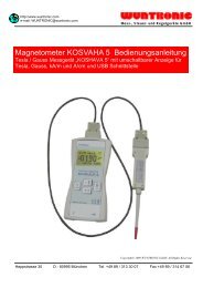
Model WOS-120<br />
Miniature Angular Orientation Sensor<br />
MSP430 CPU Version<br />
User’s Manual and Technical Reference<br />
April 2011<br />
Mess-, Steuer- und Regelgeräte <strong>GmbH</strong><br />
Heppstrasse 30 ■ D-80995 München ■ Phone +49 (89) 313 30 07 ■ Fax +49 (89) 314 67 06<br />
email: wuntronic@wuntronic.de ■ web site: www.wuntronic.de
Table of Contents<br />
Mess-, Steuer- und Regelgeräte <strong>GmbH</strong><br />
I ....... Introduction ............................................................................................................1<br />
II ...... System Specifications2..........................................................................................2<br />
III ..... Mechanical Features..............................................................................................2<br />
IV..... Electrical Interface .................................................................................................3<br />
V...... Initial Setup of the System .....................................................................................3<br />
VI..... Computer Interface ...............................................................................................4<br />
6.1 ... WOS-120 Internal Constants .................................................................................4<br />
6.2 ... ASCII Communication Mode..................................................................................6<br />
6.3 ... Changing Data Output Mode .................................................................................6<br />
6.4 ... Changing the Baud Rate........................................................................................7<br />
6.5 ... Enabling Echoing of WOS-120 Input Commands..................................................7<br />
6.6 ... Entering a Serial Number into the WOS-120 Power On Message.........................7<br />
6.7 ... Turn Off WOS-120 Power On Message.................................................................7<br />
6.8 ... Configuring the WOS-120 for Autosend Modes.....................................................8<br />
6.9 ... Averaging and Filtering of WOS-120 Data.............................................................8<br />
6.10 . Single Packet Binary Communication Modes ........................................................8<br />
6.11 . Autosend Binary Mode.........................................................................................10<br />
Comparison of ASCII and Standard Binary Data ..........................................................10<br />
Changing the WOS-120 Coordinate System (Optional)................................................12<br />
VII.... Definition and Method of Calculation of the Orientation Sensor Angles ..............13<br />
7.1 ... Sensor Based Coordinate System.......................................................................13<br />
7.2 ... Definition of Orientation Angles ...........................................................................13<br />
7.3 ... Definitions ............................................................................................................14<br />
7.4 ... Calculation of Roll and Magnetic Roll ..................................................................14<br />
7.5 ... Calculation of Inclination ......................................................................................14<br />
7.6 ... Magnetic Heading (Azimuth)................................................................................15<br />
VIII Windows Software for Model WOS-120 Orientation Sensor ..................................16<br />
Sensor Angles<br />
Table 1 System Specifications…………………………………………...............................2<br />
Table 2 WOS-120 Electrical Specifications……………………………………. .................3<br />
Table 3 RS-232 Interface Connections…………………………………. ..........................3<br />
Table 4 WOS-120 Operating Modes…………………………………………......................6<br />
Table 5 Baud Rate Settings…………………………………………….. ............................7<br />
Table 6 Autosend Modes………………………………………………................................8<br />
Table 7 Binary Data Packets……………………………………………............................11<br />
Figure 1 WOS-120 Mechanical Drawing ………………………………….. .................20<br />
Figure 2 WOS-120 Coordinate System and Orientation Angles…………….. .............21<br />
Appendix A Azimuth Accuracy Estimates …………………………. ............................22<br />
Heppstrasse 30 ■ D-80995 München ■ Phone +49 (89) 313 30 07 ■ Fax +49 (89) 314 67 06<br />
email: wuntronic@wuntronic.de ■ web site: www.wuntronic.de
Model WOS-120 Miniature Orientation Sensor User’s Manual Rev. 1.1<br />
I. Introduction<br />
This manual describes the Model WOS-120 orientation sensor. This system is designed to<br />
enable high accuracy measurement of the inclination, roll (or tool face) and azimuth<br />
orientation angles of the system to which it is mounted. A common application of the WOS-<br />
120 is to measure the orientation of borehole logging and directional drilling systems.<br />
The Model WOS-120 orientation sensor contains both a 3 axis fluxgate magnetometer and<br />
a 3 axis accelerometer. The combination of these two sensor systems enables the<br />
inclination, roll and azimuth angles of the WOS-120 reference frame to be determined.<br />
Inclination and roll angles are determined from the accelerometer subsystem, which<br />
measures the pull of gravity. After inclination and roll are known, the magnetometer<br />
subsystem is used to determine system azimuth angle. Knowledge of the inclination and<br />
roll angles enable determination of the horizontal components of the earth's local magnetic<br />
field; this information defines the azimuth angle.<br />
The WOS-120 System contains a microprocessor and 8 channels of 16-bit analog to digital<br />
conversion. Six channels are assigned to the magnetometer and accelerometer outputs.<br />
One channel provides temperature data from an internal thermometer and one channel is<br />
configured to measure the system input voltage.<br />
The WOS-120 System communicates with the outside world over one of two serial bidirectional<br />
interfaces that can be selected for either TTL or RS-232 voltage levels. An ASCII<br />
character command language has been created to facilitate communication with the WOS-<br />
120. For instance, if the ASCII string “0SD” is sent to the unit, the WOS-120 interprets<br />
this as a "send data" command and responds by sending over the serial interface an ASCII<br />
string representing the value of all magnetometer, accelerometer and temperature outputs.<br />
The leading zero in this sequence denotes the system serial number. The WOS-120 can<br />
also be configured to send angle data (roll, pitch and azimuth) instead of the accelerometer<br />
and magnetometer sensor data.<br />
An autosend data mode is included in the WOS-120 firmware. When this mode is active,<br />
data is repeatedly sent after power is applied to the system.<br />
The WOS-120 accelerometers are calibrated by placing the system in a precision rotation<br />
fixture and systematically changing the system orientation in the earth's gravitational field.<br />
The WOS-120 system magnetometers are calibrated by placing the system in a precision<br />
3-axis Helmholtz coil system, which enables the application of known magnetic fields to the<br />
system. Both the rotation fixture and Helmholtz coil mounting fixture have alignment pins<br />
and reference surfaces, which mate to the WOS-120 reference surface.<br />
When the system is calibrated over a temperature range, data is read from the system at<br />
temperature intervals between the minimum and maximum temperature specification. For<br />
instance, for calibration over the interval of 0°C – 75°C, data is read at 25°C temperature<br />
intervals between 0° and 75°C. The data taken at each temperature includes scale, offset<br />
and sensor alignment data. The recorded data is then used to create a look up table for<br />
scale offset and alignment corrections. This table is then downloaded into the WOS-120<br />
internal EEROM memory, where it can be accessed by the system internal microprocessor.<br />
Corrections to the read sensor data can then be made by the internal microprocessor<br />
system before data is transmitted.<br />
WUNTRONIC <strong>GmbH</strong> 1
Model WOS-120 Miniature Orientation Sensor User’s Manual Rev. 1.1<br />
II. System Specifications<br />
Specification<br />
Angular Accuracy<br />
Value Notes<br />
Azimuth ±1.2° Inclination=90 deg<br />
Inclination ±0.4°<br />
Roll<br />
Power<br />
±0.4°<br />
Voltage +4.9 to +12 VDC<br />
Current 55 mA<br />
Operating Temperature 0 °C – 70 °C Optional range of 0� to<br />
125�C available<br />
Vibration 10 g RMS, random 20–250Hz<br />
Shock 750 g 1ms half-sine<br />
Size 0.75" x 0.80" x 4.6"<br />
Mass<br />
Digital Outputs<br />
50 grams<br />
Logic Level TTL or RS-232 User selectable<br />
Baud rate 300 – 9600 baud User selectable<br />
Protocol ASCII text or Binary User selectable<br />
Leads 6" flying leads Color coded<br />
Data output speed in<br />
autosend mode<br />
ASCII angle mode<br />
ASCII sensor mode<br />
Binary sensor mode<br />
6 Samples/sec<br />
9 Samples/sec<br />
18 Samples/sec<br />
Table 1. WOS-120 System Specifications<br />
III. Mechanical Features of the WOS-120<br />
Data rates listed are for a<br />
filter setting of 30 Hz<br />
An outline drawing of the WOS-120 System is shown in Fig. 1. (All figures are at the end of<br />
this manual.) The system dimensions are 0.75" x 0.80" x 4.60" (1.90 cm x 2.03 cm x 11.68<br />
cm). The system is normally mounted by using four 2-56 x 0.250 long screws to secure the<br />
WOS-120 reference surface to a flat mating surface. Two 0.062" dia. x 0.125" long pins<br />
protruding from the external mating surface can be used to orient the WOS-120 on the<br />
external mounting surface. The orientation of the X-, Y- and Z- axes and the approximate<br />
location of the magnetometer and accelerometer sensors are also shown in Figure 1. The<br />
output polarity sense of the axes is such that a field pointing in the direction of the arrows<br />
shown in Fig. 1 will produce a positive output voltage. For example, if the X magnetometer<br />
is oriented so the X-axis arrow points north, then the X-axis magnetometer output will<br />
record a positive value. If the X-axis accelerometer arrow is pointed down, the X-axis<br />
accelerometer output will be positive. The orientation of the axes is silk-screened onto the<br />
WOS-120 case.<br />
Fig. 2 shows the definition of the angles output by the WOS-120.<br />
WUNTRONIC <strong>GmbH</strong> 2
Model WOS-120 Miniature Orientation Sensor User’s Manual Rev. 1.1<br />
IV. Electrical Interface of the WOS-120<br />
The WOS-120 electrical interface is shown in Table 2 below. The serial communications<br />
interface to the WOS-120 is provided by the serial in and serial out lines shown in the table.<br />
Two serial interfaces are provided. The RS-232 interface can be connected directly to an<br />
external computer COM port. The TTL serial interface is used for communication between<br />
the WOS-120 and other system electronics. The serial interfaces are normally set to<br />
operate at 9600 baud using 8 bits with one stop bit and no parity. The user, however, can<br />
change the baud rate by setting bits in the system EEROM. (See Section VIII.)<br />
Wire Color Function<br />
Red +4.9 to +12 VDC Unregulated<br />
Black Ground<br />
Orange RS-232 Serial In<br />
Yellow RS-232 Serial Out<br />
White/Orange TTL Serial In<br />
White/Yellow TTL Serial Out<br />
Table 2. WOS-120 Electrical Interface<br />
V. Initial Setup of the System<br />
In order to operate the WOS-120, power must be applied to it and an interface with an<br />
external computer must be set up. Input power should be applied to the red (+4.95 to +12<br />
VDC) and the Black (Ground) wires of the system. In order to set up a computer interface<br />
with the system, select the output protocol of the WOS-120. This can be either TTL or RS-<br />
232. The TTL protocol is usually used in microprocessor-to- microprocessor<br />
communications. Since PC serial COM ports use RS-232 protocol, they can be directly<br />
connected to a WOS-120 employing this protocol. PC’s use either a 25-pin or a 9-pin D<br />
connector on their serial ports. This connector is always a bulkhead male connector on the<br />
PC chassis. The serial in, serial out and ground connections for these connectors are<br />
shown in Table 4. The WOS-120 serial output line is connected to the computer serial in<br />
line and the WOS-120 serial input line is connected to the computer serial out line.<br />
Function WOS-120<br />
Wire<br />
25-Pin D 9-Pin D<br />
WOS-120 Serial<br />
In<br />
Orange 2 3<br />
WOS-120 Serial<br />
Out<br />
Yellow 3 2<br />
Ground Black 5 5<br />
Table 3. RS-232 Interface Connections<br />
An easy way of communicating with the WOS-120 using the ASCII protocol is to run a<br />
terminal program on the PC. The Windows HyperTerminal program is one choice for this.<br />
Other suitable terminal programs are ProComm and ASCII Pro. These programs turn the<br />
computer into a dumb terminal. In this mode, whatever you type on the keyboard goes out<br />
the selected serial port (e.g. COM 1) and whatever comes in the serial port is displayed on<br />
the computer video display.<br />
WUNTRONIC <strong>GmbH</strong> 3
Model WOS-120 Miniature Orientation Sensor User’s Manual Rev. 1.1<br />
If the program HyperTerminal is used, the proper Com port (e.g. COM 1, COM 2, etc.) must<br />
be selected. In addition, a baud rate of 9600 with one stop bit and no parity must be<br />
selected.<br />
Set the port up for direct connect and select “none “ for handshaking.<br />
After setting up communications with an external computer the WOS-120 will respond with<br />
the following startup message when power is turned on:<br />
APS: S/Nxxxxxxxxxx<br />
Ver: 3.67 Bow Dip<br />
In the above messages, the x’s represent the unit serial number.<br />
A Second method of communicating with the WOS-120 is to use the Windows program<br />
Sensor.exe described in section VIII of this manual.<br />
VI Computer Interface of the WOS-120<br />
6.1 WOS-120 Internal Binary and Float Constants<br />
The operating characteristics of the WOS-120 are controlled by the value of internal binary<br />
constants. The most important constants are:<br />
Binary constant Function<br />
00 enables echoing when non zero<br />
01 enables autosend upon power up when = 5A<br />
02 enables sensor A/D count output when zero, calibrated sensor output (in<br />
Gauss and Gees) when =2 and angle output (roll, pitch, azimuth) when =3<br />
(Alternate labels Roll: Pitch: Az: ) when =4<br />
05 Controls sending of power up sign on message (default=0, message enabled)<br />
08 Sets power on mode (e.g., 10 enables ASCII autosend upon power up)<br />
09 Baud rate lock (must be =5A if any baud rate other than 9600 is used)<br />
10 Sets baud rate<br />
23 Sets up averaging of the output<br />
35 Sets delay between transmissions in autosend mode<br />
In order to change the internal system binary constants, a write enable command must first<br />
be issued. This is:<br />
0l <br />
Where 0 is zero, l is the letter L (lower case or capital) and is a carriage return.<br />
When this command is sent to the WOS-120, it will respond with the reply<br />
enabled!<br />
To write byte constant 02=03, the command<br />
0WC0203b03 <br />
WUNTRONIC <strong>GmbH</strong> 4
Model WOS-120 Miniature Orientation Sensor User’s Manual Rev. 1.1<br />
is issued. After receiving this and acting upon it, the WOS-120 will respond with the reply<br />
done<br />
The reading of internal constants can be accomplished by issuing the command<br />
0SC02b <br />
(0 Send Constant 02 binary). When this command is sent, the WOS-120 will respond by<br />
sending the value of constant 02. Wildcards are also recognized. The command OSC*b will<br />
cause the WOS-120 to send the value of all internal binary constants.<br />
In addition to internal byte constants, the WOS-120 also has a number of float constants.<br />
These are used to store the calibration data in the WOS-120 EEROM. These constants<br />
can be read by using the commands<br />
0SC*f for all constants<br />
0SC06F for constant 06<br />
The most important float constants are:<br />
Float Constant Description<br />
04 X Magnetometer Offset<br />
05 Y Magnetometer Offset<br />
06 Z Magnetometer Offset<br />
07 X Accelerometer Offset<br />
08 Y Accelerometer Offset<br />
09 Z Accelerometer Offset<br />
10 X Magnetometer scale<br />
11 Y Magnetometer scale<br />
12 Z Magnetometer scale<br />
13 X Accelerometer scale<br />
14 Y Accelerometer scale<br />
15 Z Accelerometer scale<br />
Float constants 16 to 34 contain the system alignment coefficients. For example, float<br />
constant 17 contains data on the magnetometer X sensor alignment in the Y direction.<br />
The WOS-120 sensor is temperature compensated to insure that the accuracy of the<br />
sensor is maintained over its intended temperature range. The temperature calibration data<br />
is stored in the system EEROM memory. This data can be accessed by using the following<br />
commands:<br />
0st*b Send temperature calibration table in binary format<br />
0st*i Send temperature calibration table in integer format<br />
0st*f Send temperature calibration table in floating format<br />
6.2 ASCII Communication Mode<br />
WUNTRONIC <strong>GmbH</strong> 5
Model WOS-120 Miniature Orientation Sensor User’s Manual Rev. 1.1<br />
Communication is initiated when the external computer issues a command such as ASCII<br />
characters 0SD. The characters 0SD stand for 0 Send Data. When this command is<br />
issued, the WOS-120 will respond with a formatted output similar to the following:<br />
MX:+0.20346 AX:-0.07852<br />
MY:+0.23165 AY:+0.72136<br />
MZ:+0.29525 AZ:+0.70226<br />
T: +28.148<br />
When internal binary constant 02=02, the WOS-120 is in sensor output mode and the<br />
above numbers represent the magnetometer X, Y and Z sensor outputs in Gauss and the<br />
accelerometer outputs in Gees. When binary byte 02=03, the WOS-120 is in angle mode<br />
and<br />
The WOS-120 responses to a send data command with the following format,<br />
MX: +35.17825 AX: +198.24032<br />
MY: +90.14559 AY: +0.43326<br />
MZ: +26.76792 AZ: +1.00101<br />
T: +28.026 DA: 55.893<br />
When binary byte 02=04, the WOS-120 is in angle mode and<br />
The WOS-120 responses to a send data command with the following format,<br />
ROLL: +35.17825 MAGROLL: +198.24032<br />
PITCH: +90.14559 MAG: +0.43326<br />
HEAD: +26.76792 GRAV: +1.00101<br />
TEMP: +28.026 DA: 55.893<br />
where ROLL is gravity roll (or toolface), PITCH is inclination, HEAD is Azimuth, MAGROLL<br />
is magnetic roll, MAG is the total magnetic field, GRAV is the total gravity field , and DA is<br />
the magnetic field dip angle<br />
6.3 Changing Data Output Mode<br />
The WOS-120 can be configured to output in raw ADC counts, sensor values or angles. Data<br />
output format is determined by the value of binary constant 02 as follows:<br />
Binary 02 value Output data format<br />
0x00 Raw A/D Counts (Uncalibrated)<br />
0x02 Calibrated Sensor Outputs (Accelerometer and<br />
Magnetometers)<br />
0x03 Angular Outputs (Roll, Inc, Azimuth)<br />
0x04 Angular Outputs with Alternate labels<br />
Table 4. WOS-120 Operating Modes<br />
6.4 Changing the Baud Rate<br />
The communications baud rate can be changed by using the following sequence:<br />
1. Set binary constant 10 according to Table 1.<br />
2. Set binary constant 09 to 0x5a.<br />
3. Cycle power off and on.<br />
WUNTRONIC <strong>GmbH</strong> 6
Model WOS-120 Miniature Orientation Sensor User’s Manual Rev. 1.1<br />
The following commands illustrate setting the baud rate to 2400.<br />
0l<br />
0wc10b32<br />
0l<br />
0wc09b5a<br />
When byte constant 09 is set to any value other than 0x5a, the system baud rate is 9600.<br />
Table 5. Baud Rate Settings<br />
Baud Rate Byte 10 Value<br />
300 0x35<br />
1200 0x33<br />
2400 0x32<br />
4800 0x31<br />
9600 0x30<br />
19,200 0x38<br />
38,400 0x05<br />
6.5 Enable the Echoing of Incoming Commands<br />
It is usually desirable to enable the WOS-120 to echo the command characters sent to it.<br />
To do this, the value of the binary constant 00 must be set to a non-zero value by issuing<br />
the following sequence of commands:<br />
0l<br />
0wc00b01<br />
6.6 Enter a serial number into the WOS-120 power up sign on message<br />
Up to 10 digits of serial number can be embedded into the unit sign on message by issuing<br />
the following commands:<br />
0l<br />
0tv=xxxxxxxxxx<br />
6.7 Turn off the WOS-120 power up sign on message<br />
The WOS-120 power on message can be turned off by setting binary constant 5 to a nonzero<br />
value. Resetting binary constant 5 to 0 will enable the turn on message.<br />
6.8 Configuring for Autosend<br />
To configure the WOS-120 for autosend, binary constant 01 must to be set to 0x5a and<br />
binary constant 08 needs to be set in accordance with table 2.<br />
WUNTRONIC <strong>GmbH</strong> 7
Model WOS-120 Miniature Orientation Sensor User’s Manual Rev. 1.1<br />
AUTOSEND MODE<br />
Send ASCII data continuously on power up 0x10<br />
Send Binary Data Continuously on power up 0x11<br />
Table 6. Autosend Modes<br />
6.9 Averaging and filtering of WOS-120 Output Data<br />
Averaging of the acquired data can be enabled by setting binary constant 23<br />
according to the table shown below. The response times shown are for a full scale change in<br />
a sensor<br />
output e.g. a change from 0 gee to 1.0gee for an accelerometer or a change from 0 Gauss to<br />
0.5 Gauss for a magnetometer.<br />
Binary constant Number of averages Time to reach Time to reach to<br />
23 value n 90% of final value within 0.001 gee<br />
(seconds) or 0.001 Gauss of<br />
final value (seconds)<br />
2 2 .94 1.87<br />
4 4 1.87 3.75<br />
8 8 3.25 7.5<br />
10 16 7.5 15<br />
20 32 15 30<br />
40 64 30 60<br />
The above averaging times assume that the A to D low pass filter frequency (see discussion<br />
of the feature in the next paragraph) is set to 30 Hz. The averaging times are proportional to<br />
this frequency so for instance if the low pass filter frequency is set to 60 Hz and the number<br />
of averages is set to 8 then the time to reach 90% of the final output is 1.62 seconds.<br />
Each data output of the WOS-120 is a running average of the previous n data acquisitions.<br />
When a new data point is acquired, a new average is computed by dropping the oldest data<br />
point from the average and adding the new data point.<br />
The maximum average is 64 samples. This average feature is useful for high vibration<br />
environments when the user knows the attitude is changing slowly, but vibration produces a<br />
large amount of noise in the WOS-120 output.<br />
6.10 Single Packet Binary Communication Modes<br />
In addition to an ASCII communication mode, the WOS-120 also has several binary<br />
communications modes:<br />
Single data packet binary communications are initiated by an external computer by the<br />
issuance of a single byte command, e.g., ASCII 128. On some computers, these<br />
commands can be sent from a terminal emulator program by holding the control key down<br />
and typing the command number on the number pad on the right side of the keyboard.<br />
Command Command Definition<br />
Binary Byte 08 Value<br />
ASCII 128 send sensor data in binary format<br />
WUNTRONIC <strong>GmbH</strong> 8
Model WOS-120 Miniature Orientation Sensor User’s Manual Rev. 1.1<br />
ASCII 131 send angle data in binary format<br />
The WOS-120, upon receiving one of these commands, responds by sending a binary data<br />
packet with one of the structures described below.<br />
Command Sends All Data in an encoded Binary Format.<br />
The data is returned as:<br />
Model WOS-120 Miniature Orientation Sensor User’s Manual Rev. 1.1<br />
6.11 Autosend Binary Communication Modes<br />
Autosend binary protocol results in the transmission of data packets with the same<br />
structure as that described above for the response to binary command 128. However, when<br />
in autosend mode, data packets are automatically and continuously sent out after power is<br />
applied. Standard autosend binary mode is selected by setting up the system binary<br />
constants as follows:<br />
binary constant 08=11 selects autosend continuously<br />
binary constant 01=5a autosend enable<br />
binary constant 35=10 inserts a small delay between data packets (optional)<br />
6.12 Comparison of ASCII and standard binary data structures<br />
Consider the following data transmissions from a WOS-120, one in ASCII mode and one in<br />
Binary mode: ASCII:<br />
MX: +0.3598 AX: +0.2740<br />
MY: -0.2490 AY: -0.3510<br />
MZ: +0.0145 AZ: +0.4711<br />
TEMP: 21.74<br />
BINARY:<br />
SOT MX AX MY AY MZ AZ TEMP ANA1 ST CS EOT<br />
10 0E0E 0AB4 F646 F24A 0091 1267 087E 0320 80 05 7FFF<br />
The two data transmissions transmit the same data content, but the ASCII data<br />
transmission uses about 8 times more bytes than the binary transmission. The binary data<br />
packet is a much more efficient method of sending data. In addition, binary data is often<br />
much easier to parse than ASCII data.<br />
WOS-120 binary data packets will always start with a header byte 0x10 and end with two<br />
bytes 0x7FFF. The data is always sent most significant byte (MSB) first, then least<br />
significant byte (LSB). Angle, sensor and temperature data is sent as 16-bit signed<br />
integers.<br />
The following table shows the definition of the binary data packet for sensor mode and<br />
angle mode.<br />
Byte Sensor mode Angle Mode<br />
01 SOT = 0x10 SOT = 0x10<br />
02 MX MSB Roll MSB<br />
03 MX LSB Roll LSB<br />
04 AX MSB Mag Roll MSB<br />
05 AX LSB Mag Roll LSB<br />
06 MY MSB Inclination MSB<br />
07 MY LSB Inclination LSB<br />
08 AY MSB Mag Total MSB<br />
09 AY LSB Mag Total LSB<br />
10 MZ MSB Azimuth MSB<br />
11 MZ LSB Azimuth LSB<br />
12 AZ MSB Total Accel MSB<br />
13 AZ LSB Total Accel LSB<br />
14 Temperature MSB Temperature MSB<br />
WUNTRONIC <strong>GmbH</strong> 10
Model WOS-120 Miniature Orientation Sensor User’s Manual Rev. 1.1<br />
15 Temperature LSB Temperature LSB<br />
16 Analog MSB Analog MSB<br />
17 Analog LSB Analog LSB<br />
18 ST ST<br />
19 Checksum Checksum<br />
20 EOT MSB = 0x7F EOT MSB = 0x7F<br />
21 EOT LSB = 0xFF EOT LSB = 0xFF<br />
Table 7. Binary Data Packets<br />
Magnetometer and accelerometer sensor values can be decoded by first converting to<br />
decimal and then dividing by 10,000. For instance, in the above transmission:<br />
MX = 0E0E = 3598/10,000 = 0.3598 Gauss<br />
MY = F646 = -2490/10,000 = -0.2490 Gauss<br />
AX = 0AB4 = 2740/10,000 = 0.2740 Gee<br />
Angles are decoded by converting to a decimal value and then dividing by 100. If the<br />
above data packet was data sent in angle mode, you would have:<br />
MX = 0E0E = 3598/100 = 35.98 ° Roll<br />
AX = 0AB4 = 2740/100 = 27.40 ° Magnetic Roll<br />
Total magnetic field and total acceleration are decoded using the same conversion as the<br />
normal sensor values (divide by 10,000.)<br />
Temperature is decoded by converting to decimal and dividing by 100<br />
TEMP = 087E = 2174/100 = 21.74°C<br />
The ANALOG MSB and ANALOG LSB transmission represents the WOS-120 voltage.<br />
This voltage can be decoded by dividing by 100:<br />
ANA1 = 320=800/100 = 8.0 (VDC)<br />
The ST byte is a status byte that is unused in the WOS-120. The value of this byte will<br />
have no meaning.<br />
The CS byte is a checksum. The checksum is calculated by summing all of the bytes in the<br />
transmission before the CS byte excluding the SOT and status (ST) characters. For the<br />
above transmission the checksum is calculated as follows:<br />
CS = 0E+0E+0A+B4+F6+46+F2+4A+00+91+12+67+08+7E+03+20 = 0505<br />
The checksum is the lower byte of the sum, or 05.<br />
6.13 Changing the WOS-120 Coordinate System (Optional Feature not present in all<br />
WOS-120s)<br />
WUNTRONIC <strong>GmbH</strong> 11
Model WOS-120 Miniature Orientation Sensor User’s Manual Rev. 1.1<br />
The directions of the X, Y and Z axes of the WOS-120 can be changed by selecting the<br />
values of binary constants 47-52 in accordance with the following list:<br />
Binary constant Description<br />
47 Controls Magnetometer X<br />
48 Controls Magnetometer Y<br />
49 Controls Magnetometer Z<br />
51 Controls Accelerometer X<br />
50 Controls Accelerometer Y<br />
52 Controls Accelerometer Z<br />
The axes can be selected by setting the appropriate binary constant as follows:<br />
Magnetometer X=0x00<br />
Magnetometer Y=0x01<br />
Magnetometer Z=0x02<br />
-(Magnetometer X)=0x80<br />
-(Magnetometer X)=0x81<br />
-(Magnetometer X)=0x82<br />
Accelerometer X=0x10<br />
Accelerometer X=0x11<br />
Accelerometer X=0x12<br />
-(Accelerometer X)=0x90<br />
-(Accelerometer X)=0x90<br />
-(Accelerometer X)=0x90<br />
The default value of the constants 47-52 selects the standard APS coordinate system shown<br />
in Fig. 2. The default values of the axis selection constants are:<br />
Binary constant Description<br />
47 0x00<br />
48 0x01<br />
49 0x02<br />
50 0x10<br />
51 0x11<br />
52 0x12<br />
A coordinate system in which the X and Z axes have been interchanged can be selected by<br />
using the following constants:<br />
Binary constant Description<br />
47 0x02<br />
48 0x01<br />
49 0x00<br />
50 0x12<br />
51 0x11<br />
WUNTRONIC <strong>GmbH</strong> 12
Model WOS-120 Miniature Orientation Sensor User’s Manual Rev. 1.1<br />
51 0x10<br />
52<br />
For this coordinate system, the system Z axis is oriented parallel to the long axis of the WOS-<br />
120. To reverse the direction of the magnetometer Z axis in the above coordinate system<br />
change the value of binary constant 49 from 0x00 to 0x80<br />
VII Definition and Method of Calculation of the Orientation<br />
Sensor Angles<br />
This section provides a definition of the system orientation angles and describes how to<br />
calculate them from accelerometer and magnetometer sensor outputs.<br />
7.1 Sensor Based Coordinate System<br />
The coordinate system of the WOS-120 System is defined in Fig. 2. The accelerometer and<br />
magnetometer coordinate systems are both aligned with the physical package coordinate<br />
system. For the magnetometer sensors, a positive output voltage will result if the sensor is<br />
pointed north. For the accelerometers, a positive voltage will result if the sensors are<br />
pointed down.<br />
7.2 Definition of Orientation Angles<br />
Azimuth is defined as the angle measured from magnetic north (clockwise from above) to<br />
the projection of the X axis on the horizontal plane.<br />
Inclination is the angle that the X axis makes with the down direction and is 0° when the X<br />
axis is down and 90° when the X axis is horizontal.<br />
Roll or gravity tool face is defined as the angle of counterclockwise rotation about the X axis<br />
(looking in the positive X axis direction) required to zero the Y axis accelerometer output<br />
and position the Z axis accelerometer so that its output polarity is positive.<br />
Magnetic roll or magnetic toolface is defined as the angle of counterclockwise rotation<br />
about the X axis (looking in the positive X axis direction) required to zero the Y axis<br />
magnetometer output and position the Z axis magnetometer so that its output polarity is<br />
negative.<br />
Magnetic roll is useful in defining the WOS-120’s orientation when inclination is near<br />
vertical, generally less than 5°. In this situation, g y and g z are near zero and roll and<br />
azimuth calculations become less accurate.<br />
7.3 Definitions<br />
The following sections describe equations for determining the WOS-120 orientation angles.<br />
These equations make use of the following definitions:<br />
g x accelerometer x axis output<br />
g y accelerometer y axis output<br />
g z accelerometer y axis output<br />
H x magnetometer x axis output<br />
WUNTRONIC <strong>GmbH</strong> 13
Model WOS-120 Miniature Orientation Sensor User’s Manual Rev. 1.1<br />
H y magnetometer y axis output<br />
H z magnetometer z axis output<br />
7.4 Calculation of Roll and Magnetic Roll<br />
The roll angle, �, is determined by using the following equations (0 < � < 2 �)<br />
g z<br />
Cos � = ─────────<br />
(g y 2 +gz 2 ) ½<br />
g y<br />
Sin � = ─────────<br />
(g y 2 +g z 2 ) ½<br />
g y<br />
Tan � = ─────────<br />
g z<br />
Roll is 0° when g y = 0 and g z > 0. Roll is 2� radians when g y = 0 and g z < 0.<br />
When the x axis is near vertical (pitch < 5°), the quantities g y and g z become<br />
very small and the above expressions yield a less accurate value of �. In this situation,<br />
magnetic roll is often used to determine the angular orientation of the WOS-120 about the<br />
longitudinal (X) axis. Magnetic roll, � m , is given by the following (0 < � < 2 �)<br />
-H y<br />
Sin � m = ─────────<br />
(H y 2 +Hz 2 ) ½<br />
-H z<br />
Cos � m = ─────────<br />
(H y 2 +Hz 2 ) ½<br />
H y<br />
Tan � m = ─────────<br />
H z<br />
7.5 Calculation of inclination<br />
Inclination, ε, is determined from the following equations 0
Model WOS-120 Miniature Orientation Sensor User’s Manual Rev. 1.1<br />
g x<br />
where g = (g x 2 +gy 2 +gz 2 ) ½<br />
Inclination is 0 when the WOS-120 X axis is pointed down and 90° when horizontal.<br />
7.6 Magnetic Heading (Azimuth)<br />
We first give expressions for the magnetic field in a horizontal reference defined by X1, Y1<br />
and Z1, where X1 is aligned with the projection of the WOS-120 X axis in the horizontal<br />
plane and Z1 is down.<br />
H x (g y 2 +gz 2 )-Hy g y g x -H z g x g z<br />
H x1 = ───────────────────────────<br />
g(g y 2 +gz 2 ) ½<br />
H y g z -H z g y<br />
H y1 = ────────────<br />
(g y 2 +gz 2 ) ½<br />
H x g x +H y g y +H z g z<br />
H z1 = ────────────────<br />
g<br />
Magnetic heading, ø, is then given by (0 < ø
Model WOS-120 Miniature Orientation Sensor User’s Manual Rev. 1.1<br />
Install the Sensor software by using the following procedure:<br />
1. Insert the CD-ROM containing the Sensor software into the CD-ROM drive.<br />
2. Click on “My Computer” and then click on the disk drive the software disk was<br />
inserted into.<br />
3. Left click and hold on the Sensor icon and drag it to the desktop. Release<br />
mouse button. The software icon should now be on your desktop and the<br />
software ready to use.<br />
MODEL WOS-120 MAIN DISPLAY USING SENSOR<br />
SOFTWARE<br />
The figure above shows the main display of the Sensor Interface Program. The upper left<br />
corner of the main window contains the command buttons. The Monitor button brings up<br />
the monitor window and the Configure button brings up the configuration window. The Stop<br />
button issues the command to the sensor to stop sending data. The Auto button issues the<br />
command to the sensor to send data repeatedly. The Once button issues the command to<br />
send the data one time.<br />
In the View menu, each check mark before Magnetometer Min/Max or AC/DC Magnetic<br />
enables or disables the feature from appearing on the screen. In the example display, the<br />
Magnetometer Min/Max is enabled.<br />
In the Graph menu, each check mark before Magnetic X, Y, Z, T, Mag Roll and Azimuth<br />
labels enables or disables the item to be scrolled on the graph. The color of the item on the<br />
graph matches the color of the text in the numeric display windows.<br />
The minimum and maximum values are tracked and displayed in the upper right corner<br />
window. The values can be reset back to zero by pressing the Reset button.<br />
The number of packets per second the sensor is receiving is displayed as Sensor Rate.<br />
This value is continually being updated and sampled.<br />
WUNTRONIC <strong>GmbH</strong> 16
Model WOS-120 Miniature Orientation Sensor User’s Manual Rev. 1.1<br />
When the Configure button is pressed, the following window is displayed:<br />
SENSOR CONFIGURATION WINDOW<br />
The Graph Speed represents the maximum scrolling speed of the graph on the main<br />
window in frames per second. The PC operating system limits the maximum scrolling<br />
speed. The Scale Refresh Time sets the time at which the auto-scaling routine can<br />
decrease the scale factors on the main scrolling window. When the scrolling window scale<br />
maximum output is exceeded, it is automatically increased. To decrease the scale, Scale<br />
Refresh Timer is used. The Check Sum box allows the sensor to send a check sum with<br />
each data packet from the sensor. The Long-Term Avg. AC/DC value is the number of<br />
samples of AC and DC values that are collected in order to create the AC and DC values<br />
display on the main window.<br />
The computer serial port to be used with the WOS-120 may be set from Com 1 to Com 8.<br />
The default baud rate is 9600 baud. Other baud rates may be selected using this panel.<br />
To use the WOS-120, the operator selects the WOS-120 in the top Sensor window. In the<br />
next window, below, the option for ASCII or Binary transfer may be entered. ASCII transfers<br />
may easily be viewed from the monitor window. Binary transfers are always faster. Raw<br />
data is expressed in A/D counts. Corrected data is in Gauss and has been corrected for<br />
physical misalignments, scale factors and offsets.<br />
To save data output from the WOS-120, the operator may enter a logging file name. This<br />
file will capture all data sent to the program from the sensor. The type of data logged is set<br />
in the menu in the Monitor Window and can be either ASCII for Logging or Hex for Logging.<br />
WUNTRONIC <strong>GmbH</strong> 17
Model WOS-120 Miniature Orientation Sensor User’s Manual Rev. 1.1<br />
The monitor sensor window allows the operator to view the data being sent from the sensor<br />
and allows the operator to send commands to the sensor.<br />
MONITOR SENSOR DISPLAY MODES<br />
The monitor window (see figure above) has a number of display modes. They are ASCII,<br />
Hex, ASCII for Logging, Hex for Logging, Hex and ASCII, and Decoded. In ASCII mode<br />
(see figure below), the monitor window acts like a simple ASCII terminal. In Hex mode (see<br />
figure below), each ASCII character received is converted to the hexadecimal value that it<br />
represents, followed by a space. For example, the ASCII character ‘A’ would be printed as<br />
‘41’, which is its hexadecimal value. ASCII for Logging and Hex for Logging are designed<br />
to be used with file logging mode. They are formatted with a at the end of each<br />
line so that then can be written into a Logging file. Hex and ASCII is a mixed display with<br />
hexadecimal data on the left and the same ASCII data on the right. Decoded is a mode<br />
where only the processed data values are displayed.<br />
MONITOR SENSOR WINDOW FOR CORRECTED ASCII MODE<br />
Note that sensor commands may be directly entered from the monitor window.<br />
The monitor window (see Fig. 3) has a number of display modes. They are ASCII, Hex,<br />
ASCII for Logging, Hex for Logging, Hex and ASCII, and Decoded. In ASCII mode (see<br />
Fig. 6), the monitor window acts like a simple ASCII terminal. In Hex mode (see Fig. 4),<br />
each ASCII character received is converted to the hexadecimal value that it represents,<br />
followed by a space. For example, the ASCII character ‘A’ would be printed as ‘41’, which<br />
is its hexadecimal value. ASCII for Logging and Hex for Logging are designed to be used<br />
with file logging mode. They are formatted with a at the end of each line so that<br />
then can be written into a Logging file. Hex and ASCII is a mixed display with hexadecimal<br />
data on the left and the same ASCII data is on the right. Decoded is a mode where only<br />
the processed data values are displayed.<br />
MONITOR SENSOR WINDOW FOR CORRECTED HEX MODE<br />
WUNTRONIC <strong>GmbH</strong> 18
Model WOS-120 Miniature Orientation Sensor User’s Manual Rev. 1.1<br />
Fig. 1. WOS-120 Mechanical Diagram<br />
Fig. 2. WOS-120 Coordinate System and Orientation Angles.<br />
WUNTRONIC <strong>GmbH</strong> 19
Model WOS-120 Miniature Orientation Sensor User’s Manual Rev. 1.1<br />
Appendix A. Azimuth Accuracy Estimates<br />
WUNTRONIC <strong>GmbH</strong> 20
Model WOS-120 Miniature Orientation Sensor User’s Manual Rev. 1.1<br />
A.1 Orientation Sensor Azimuth Accuracy as a Function of the Earth’s Magnetic<br />
Field Dip Angle<br />
Orientation sensors measure the horizontal component of the Earth’s magnetic field, using<br />
accelerometers, to determine vertical. At high magnetic field dip angles the vertical<br />
component of the magnetic field becomes much larger that the horizontal component. This<br />
has the consequence that small uncertainties in the direction of down, or small<br />
misalignments of the sensors, can result in large errors in azimuth. At a dip angle of 90<br />
degrees, there is no horizontal component, and an orientation sensor based upon the<br />
measurement of acceleration and magnetic field will no longer be able to determine<br />
azimuth. The following table gives expected errors in azimuth due to sensor errors of 1mg<br />
for accelerometers and 0.5mG for the magnetometers. These errors could arise from<br />
measurement inaccuracy or sensor misalignment. It is assumed that the pitch is in the<br />
middle range –20 to 20 degrees. The errors were nearly independent of azimuth and roll.<br />
Accuracy may be less than shown for small dip angles, due to imperfect calibration, and<br />
other systematic errors, but will be less than 0.3 degrees. Azimuth accuracy also degrades<br />
as the inclination approaches 90 degrees, but this is a coordinate system singularity and<br />
does not reflect any underlying error in orientation.<br />
Dip angle Azimuth Error<br />
(degrees) (degrees)rms<br />
89 5<br />
87.5 2<br />
85 1<br />
80 0.5<br />
70 0.26<br />
67 0.23<br />
60 0.175<br />
0 0.072<br />
A.2 Orientation Sensor Azimuth Accuracy as a function of the Inclination<br />
Azimuth accuracy becomes poor as one approaches inclination of 0 degrees (vertical).<br />
(Refer to figure 2 for a definition of the WOS-120 coordinate definition.) This is not the<br />
result of a real degradation of sensor performance, but is an artifact of the coordinate<br />
system, which is singular at an inclination of 0 degrees. The following graph shows the<br />
uncertainties in azimuth, as a function of inclination. At small inclination angles, the error is<br />
approximately 1/Inclination, while at larger angles, error will be dominated more by<br />
systematic errors, such as imperfect calibration. It is assumed for this calculation that the<br />
accelerometers are accurate to 0.001g and the magnetometers are accurate to 0.0005<br />
Gauss. The dip angle is assumed to be 60 degrees. When the system is to be used at<br />
small inclination angles, the user can use the magnetic roll calculations shown in 11.4 as an<br />
alternative to the azimuth output.<br />
WUNTRONIC <strong>GmbH</strong> 21
Model WOS-120 Miniature Orientation Sensor User’s Manual Rev. 1.1<br />
Error in degrees<br />
7<br />
6<br />
5<br />
4<br />
3<br />
2<br />
1<br />
0<br />
Azimuth Error (degrees)<br />
0 5 10 15 20<br />
Inclination in degrees<br />
WUNTRONIC <strong>GmbH</strong> 22