Download - Wuntronic GmbH
Download - Wuntronic GmbH
Download - Wuntronic GmbH

Create successful ePaper yourself
Turn your PDF publications into a flip-book with our unique Google optimized e-Paper software.
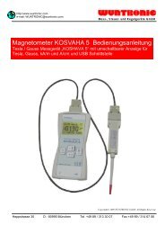
http://www.wuntronic.de<br />
e-mail: WUNTRONIC@wuntronic.de<br />
Mess-, Steuer- und Regelgeräte <strong>GmbH</strong><br />
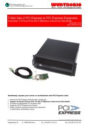
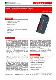
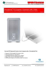
2 Channel USB 2.0 / PXIe Digitizer w. 14-Bit, 400 MS/s<br />
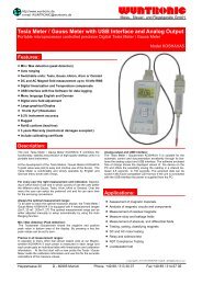
Description:<br />
The ADQ 214 Digitizer is a two channel data acquisition<br />
card featuring two 14-bit, 400 MSPS AD-converters and a<br />
USB 2.0 interface. The high speed data acquisition capabilities<br />
in combination with the high performance FPGA<br />
makes it feasible for demanding applications such as<br />
emerging wireless standards or for high speed data recording.<br />
The high input bandwidth of 1.4 GHz makes it suitable for<br />
IF sampling of RF signals.<br />
ADQ 214 is equipped with a Xilinx Virtex5 LX50T FPGA<br />
with 32 MSample/channel integrated memory.<br />
The ADQ 214 Digitizer has three available trigger modes of<br />
operation:<br />
USB Trigger Mode (default mode): The device collects a<br />
data batch when triggered by an USB-command.<br />
External Trigger Mode: Allows the device to capture data<br />
when triggered by an external trigger signal.<br />
Mixed Trigger Mode: This mode allows the device to be<br />
triggered by either a USB-command or by an external trigger<br />
signal<br />
Software tools for host development include C++, Matlab<br />
and basic program modules for Windows XP/Vista as well<br />
as data capture tool ADCapture Lab are included.<br />
ADCapture Lab<br />
ADCapture Lab is an application<br />
for configuration and operation of<br />
the ADQ series data acquisition<br />
cards. It visualizes the collected<br />
data and calculates key parameters.<br />
Data can also be stored to<br />
make comparison of results easy.<br />
ADCapture Lab is included in all<br />
ADQ series products and evaluation board<br />
Features:<br />
Model xxx-ADQ-214<br />
�� 14 Bit Resolution<br />
�� 2 Channels each with 400 MS/s Sampling Rate<br />
�� 64 MS On-Board Memory<br />
�� Up to 500 MHz Input bandwidth<br />
�� Available for USB 2.0 and PXI Express<br />
�� Software tools for host development include<br />
LabVIEW, ++, Matlab under WIN XP and Vista<br />
�� Programming of own DSP Developments<br />
�� OEM board only Version for USB 2.0 available<br />
Accelerating your DSP Development<br />
The ADQ development kit is<br />
a comprehensive tool that<br />
rapidly enhance the development<br />
of your next DSP application.<br />
The development kit<br />
includes design tools, reference<br />
projects and 5 hours<br />
off-site support to speed up<br />
development of your own<br />
applications. The development kit is tailored to fit the development<br />
environmentprovided by Xilinx and is compatible<br />
with all IP-blocks available from Xilinx<br />
Applications:<br />
�� Portable Test and Measurement Systems<br />
�� Ultrasonic Testing<br />
�� Lidar Systems<br />
�� Communications<br />
�� Spectroscopy<br />
�� Radar Systems<br />
�� Military<br />
Copyright© 2009 WUNTRONIC <strong>GmbH</strong>. All Rights Reserved<br />
Heppstrasse 30 D - 80995 München Phone +49 (89) 313 30 07 Fax +49 (89) 314 67 06
Spezifications<br />
Analog input<br />
Number of channels.............................................. 2<br />
Resolution.................................................... 14 bits<br />
ENOB @ 33 MHz...................................... 11.2 bits<br />
SFDR @ 33 MHz .........................................87 dBc<br />
SNDR @ 33 MHz........................................69.4 dB<br />
Sampling rate..................................34 - 400 MSPS<br />
Connector ....................................................... SMA<br />
Impedance ................................................. 50 Ohm<br />
Coupling....................................AC / (DC Optional)<br />
AC-coupled bandwidth...............................1,4 GHz<br />
Input voltage range .....................................2.0 VP-P<br />
Acquisition memory<br />
Data storage ..............................On board memory<br />
Memory buffers...................................1 MSamples<br />
Variable buffer length to<br />
shorten transfer times<br />
Extended memory.................. Up to 64MSamples /<br />
channel (optional)<br />
Triggering<br />
Trigger source.......External, Software, Signal level<br />
Signal level trigger .................. Software adjustable<br />
Slope...................................... Software selectable:<br />
positive / negative<br />
Pre-trigger data.................................2048 samples<br />
External triggering<br />
Impedance ............................................1 M , 35 pF<br />
Voltage range ........................................... 0 - 3.3 V<br />
Coupling.............................................................DC<br />
Trigger threshold.............................................0.7 V<br />
Connector ....................................................... SMA<br />
Trigger edge.................................................. Rising<br />
Internal clock<br />
Source...............................................Low-jitter PLL<br />
Accuracy ........................................... ± 150 fs RMS<br />
Reference clock ............................10 MHz external<br />
On-board TCXO<br />
PXIe reference clock<br />
External clock<br />
Maximum frequency .................................400 MHz<br />
Minimum frequency ....................................34 MHz<br />
Signal level ...................................Minimum 1 VRMS<br />
Maximum 2 VRMS<br />
Termination impedance ............................. 50 Ohm<br />
Sampling edge............................ Rising and falling<br />
Duty cycle ...............................................50% ± 3%<br />
Connector ....................................................... SMA<br />
Coupling............................................................. AC<br />
Power<br />
Supply voltage ........................................ 6.5 - 12 V<br />
Power consumption ............................9 W (typical)<br />
USB 2.0 interface<br />
Plug and play....................................................Yes<br />
Bus speed............................................ 480 Mbit / s<br />
Connector ....................................................Type B<br />
PXI Express interface<br />
Plug and play................................................... Yes<br />
Bus width .....................................................8 lanes<br />
Bus speed...............................................16 Gbit / s<br />
Dimensions<br />
Card size (mm) OEM Version................. 100 x 160<br />
USB Box size (mm) ........................ 103 x 163 x 31<br />
PXIe card ......................................... 1 slot, 3U 4TE<br />
Operating systems<br />
Windows XP ................................. SP 2 and higher<br />
Windows 2000 .............................. SP 1 and higher<br />
Windows Vista ......................................All versions<br />
Application software<br />
ADCaptureLab .............. Data capture and analysis<br />
software provided<br />
with the ADQ114 at purchase.<br />
Matlab Data ................................. capture interface<br />
LabVIEW..............................Data capture interface<br />
C++ Data ..................................... capture interface<br />
ADQ-214-Dual: Dual Interface version<br />
Delivered for PXI rack mounting and with USB 2.0 Interface<br />
Orderinformations:<br />
Order number Model Description<br />
WA50-200-100 USB-ADQ114-U 14 Bit, 2-Ch, 400 MSPS, 64 MS Memory,<br />
USB Box<br />
WA50-200-110 USB-ADQ114-<br />
UC<br />
14 Bit, 2-Ch, 400 MSPS, 64 MS Memory,<br />
USB OEM Version board only<br />
WA50-200-120 PE-ADQ114-P 14 Bit, 2-Ch, 400 MSPS, 64 MS Memory<br />
PXI Express<br />
WA50-200-130 Dual-ADQ114 14 Bit, 2-Ch, 400 MSPS, 64 MS Memory<br />
PXI Express and USB<br />
Options for USB and PXI Express Digitizer xxx-ADQ-114<br />
WA50-204-100 MEM128 64 MS Memory Upgrade