N2x3 / ELC - eta plus electronic GmbH
N2x3 / ELC - eta plus electronic GmbH
N2x3 / ELC - eta plus electronic GmbH

Create successful ePaper yourself
Turn your PDF publications into a flip-book with our unique Google optimized e-Paper software.
���<br />
our name is our principle<br />
UV<br />
TECHNOLOGY<br />
Technical Documentation<br />
<strong>ELC</strong> ® <strong>N2x3</strong> / <strong>ELC</strong> ® N2x4<br />
�<br />
GB<br />
<strong>eta</strong> <strong>plus</strong> <strong>electronic</strong> gmbh<br />
Lauterstraße 29, D-72622 Nürtingen, Telefon +49 (0) 70 22 - 60 02-80, Fax +49 (0) 70 22 – 6 58 54<br />
Postfach 1411, D-72604 Nürtingen, e-mail: info@<strong>eta</strong>-uv.de<br />
––––––––––––––––––––––––––––<br />
Eingetragen unter HRB 724321 AG Stuttgart, USt.-Id.-Nr. DE 146267800<br />
Geschäftsführer: Dr. Peter Schwarz-Kiene
<strong>ELC</strong> ® („Electronic Lamp Control“) is a registered trademark of<br />
IST Metz <strong>GmbH</strong>.<br />
<strong>ELC</strong> <strong>N2x3</strong>_N2X4-V4.0-09/11-GB Subject to technical alterations
Contents page I<br />
Contents<br />
1 Safety ................................................................................................. 1<br />
1.1 Definition of Symbols.................................................................................1<br />
1.2 Safety Advice ..............................................................................................1<br />
1.3 Correct operation........................................................................................2<br />
1.4 Extended use ..............................................................................................2<br />
2 Description of functions................................................................... 3<br />
3 Installation......................................................................................... 4<br />
3.1 Mounting of casing.....................................................................................4<br />
3.1.1 Back mounting ................................................................................................5<br />
3.1.2 Side by side rack mounting.............................................................................6<br />
3.2 Connection ..................................................................................................8<br />
3.3 Control current connections....................................................................12<br />
3.4 Explanations of the control functions for <strong>ELC</strong>.......................................14<br />
3.4.1 Release relay................................................................................................14<br />
3.4.2 Control input START.....................................................................................14<br />
3.4.3 Setting lamp power .......................................................................................14<br />
3.4.4 Table: lamp power ........................................................................................15<br />
3.4.5 Earth fault control..........................................................................................16<br />
4 Operation of <strong>ELC</strong> ............................................................................ 17<br />
4.1 Initial operation .........................................................................................17<br />
4.2 Switching on the <strong>ELC</strong>...............................................................................17<br />
4.3 Switching on the lamp..............................................................................17<br />
4.4 Dimming Operation ..................................................................................18<br />
4.5 Standby Operation....................................................................................18<br />
4.6 Switching off the Lamp ............................................................................18<br />
5 Troubleshooting.............................................................................. 19<br />
5.1 Repair <strong>ELC</strong> ................................................................................................19<br />
6 Technical Data................................................................................. 20<br />
<strong>ELC</strong> <strong>N2x3</strong>_N2X4-V4.0-09/11-GB Subject to technical alterations
1 Safety page 1<br />
1 Safety<br />
1.1 Definition of Symbols<br />
�<br />
Stop (Stop Danger). This symbol warns of serious danger of severe injury to<br />
persons. It must be strictly observed.<br />
Attention (Warning). This symbol indicates information the non-observance of<br />
which can lead to extensive damage to property. The safety warning must be<br />
strictly observed.<br />
Information. This symbol indicates key information on use. Non-observance can<br />
lead to failure.<br />
1.2 Safety Advice<br />
The <strong>ELC</strong> must be installed and connected in compliance with existing<br />
regulations and practices. This is e.g. EN 60204-1 in Europe.<br />
Repairs on the <strong>ELC</strong> may only be carried out by the manufacturer.<br />
The installation and starting up may only be carried out by skilled electricians.<br />
Do not open the <strong>ELC</strong> before it is disconnected from the mains. BEWARE OF<br />
RESIDUAL VOLTAGE! The unit may still be live up to three minutes after it has<br />
been switched off.<br />
<strong>ELC</strong> <strong>N2x3</strong>_N2X4-V4.0-09/11-GB Subject to technical alterations
1 Safety page 2<br />
The <strong>ELC</strong> causes a leakage current greater than 3.5 mA!<br />
Safeguarding by means of leakage current protection type A and type AC<br />
according to IEC 60755 is not permitted!<br />
The <strong>ELC</strong> operates in principle as a frequency converter and is equipped with a<br />
mains filter whose leakage current could activate fuse protection.<br />
Contact to the grounding connector must always be ensured.<br />
Additional measures must be taken to ensure that there is no danger when<br />
touching the appliance. This could be by means of a universal leakage current<br />
protection type B, taking into consideration the increased response threshold, or<br />
by means of an independent equipotential connection<br />
1.3 Correct operation<br />
The <strong>ELC</strong> is an electrical unit intended to be installed in the switch cabinets of<br />
industrial high-voltage power installations. It is conceived as an <strong>electronic</strong> ballast<br />
for the operation of lamps intended for this purpose.<br />
Any other use is deemed as misuse. The manufacturer will not assume liability<br />
for damage resulting from misuse.<br />
A pre-requisite for authorised operation of the <strong>ELC</strong> is the observance of both the<br />
operating and maintenance instructions and the safety advice.<br />
1.4 Extended use<br />
Extended use beyond the operating specifications as stated is not permitted.<br />
The manufacturer will not assume liability if the equipment is used in any other<br />
way. The operator acts at his own risk.<br />
Any operation beyond the scope of the authorised operation is considered to be<br />
misuse.<br />
<strong>ELC</strong> <strong>N2x3</strong>_N2X4-V4.0-09/11-GB Subject to technical alterations
2 Description of functions page 3<br />
2 Description of functions<br />
The <strong>electronic</strong> ballast <strong>ELC</strong> is designed to operate medium pressure discharge lamps as<br />
described in chapter 6. The appliances of type <strong>ELC</strong> N2x have two outputs which means that<br />
two UV lamps can be connected and each operated separately.<br />
In contrast to conventional ballasts (inductive lamp ballast or transformer or transformer with<br />
transductor), the lamp with an <strong>electronic</strong> ballast is operated with high frequency (approx.<br />
100 kHz). The lamp does not flicker and dimming is infinitely adjustable to a range between<br />
20 % and 100 % of the electric power or to between 15 % and 100 % of the UV radiation<br />
respectively.<br />
Dimming<br />
The possibility of dimming the lamp has two advantages. Firstly the lamp can be switched to<br />
minimum load (standby operation) during longer idle times and energy can thus be saved.<br />
Secondly the optimum lamp power can be determined and adjusted as appropriate.<br />
Power control<br />
The <strong>ELC</strong> offers a high level of lamp power constancy due to its integrated power control.<br />
Variations in operating voltage of ± 10 % do not affect lamp power.<br />
Ignition device<br />
When the lamp is switched on the <strong>ELC</strong> initiates trigger pulses to fire the lamp; a separate<br />
ignition device is not required.<br />
Other performance characteristics<br />
• High level of electrical efficiency.<br />
• The <strong>ELC</strong> has a network power factor of > 0.9. It can be operated directly at the network<br />
without compensation.<br />
• The potential-free control inputs allow various lamp conditions such as maximum lamp<br />
power, dimming or standby to be set.<br />
• The digital control inputs are designed for control voltages of between 10 and 30 V AC or<br />
DC. Therefore <strong>ELC</strong> can be easily integrated into the installation’s electric system.<br />
• Lamp current and lamp power are continuously recorded and output as analogous<br />
0-10 V signals.<br />
• The <strong>ELC</strong> monitors the lamp cables for earth fault.<br />
• The potential of both lamp outputs is separated from that of the supply voltage.<br />
• The <strong>ELC</strong> is both short-circuit proof and safe in open circuit operation at the lamp output.<br />
<strong>ELC</strong> <strong>N2x3</strong>_N2X4-V4.0-09/11-GB Subject to technical alterations
3 Installation page 4<br />
3 Installation<br />
3.1 Mounting of casing<br />
The <strong>ELC</strong> must be installed in a control cabinet with at least IP 54 protection (see<br />
EN 60529). Operation without a control cabinet or in a control cabinet with a<br />
lower degree of protection is not permitted.<br />
The <strong>ELC</strong> may only be installed vertically (control connections at the bottom,<br />
power connection at the top) allowing for at least the minimum spacing as<br />
shown. No other positioning is possible.<br />
Fig. 1 and Fig. 2 show the installation possibilities.<br />
The <strong>ELC</strong> should not be mounted in the immediate proximity of sensitive<br />
<strong>electronic</strong> equipment. An appropriate distance must be maintained to scatter<br />
field transformers or other inductors.<br />
The flow of cool air in <strong>ELC</strong> must be safeguarded. The ambient temperature must<br />
not exceed the values described in chapter 6!.<br />
The switching cabinet has to be air conditioned in consideration of total electrical<br />
losses and maximum ambient temperature.<br />
If the air conditioning is realised by fans the minimum required air flow is<br />
described in chapter 6. The better the cooling situation the higher the expected<br />
lifetime.<br />
Impure cooling air could affect the functionality of the <strong>ELC</strong>. This can be avoided<br />
by installing a fine air filter.<br />
<strong>ELC</strong> <strong>N2x3</strong>_N2X4-V4.0-09/11-GB Subject to technical alterations
3 Installation page 5<br />
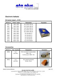
3.1.1 Back mounting<br />
min. 20<br />
min. 50<br />
pin-and-socket connector<br />
for control signals<br />
319 mm<br />
min. 20<br />
min. 20<br />
Assembly for instance by gudgeon M6 with distance sleeve<br />
500 mm<br />
23 mm 270 mm<br />
23 mm<br />
Lamp feeder cable<br />
Top<br />
mains connection<br />
Fig. 1: Assembly of the <strong>ELC</strong> (all dimensions in mm).<br />
130 mm<br />
<strong>ELC</strong> <strong>N2x3</strong>_N2X4-V4.0-09/11-GB Subject to technical alterations<br />
min. 100 min. 100<br />
90 mm<br />
473 mm
3 Installation page 6<br />
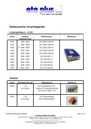
3.1.2 Side by side rack mounting<br />
473 mm<br />
130 mm<br />
pin-and-socket connector<br />
for control signals<br />
min. 50<br />
min. 100<br />
min. 100<br />
Top<br />
Lamp feeder connection<br />
321 mm<br />
min. 20<br />
mains connection<br />
<strong>ELC</strong> <strong>N2x3</strong>_N2X4-V4.0-09/11-GB Subject to technical alterations<br />
539 mm<br />
23 mm<br />
Fig. 2 side by side rack mounting with brackets<br />
80 mm<br />
520 mm<br />
M8 (4x)
3 Installation page 7<br />
If “side-by-side rack mounting“ is preferred, assembly brackets and screws can be provided<br />
upon request.<br />
<strong>ELC</strong> <strong>N2x3</strong>_N2X4-V4.0-09/11-GB Subject to technical alterations<br />
Attach bracket to the upper surface of the<br />
appliance<br />
Attach bracket to the underside of the appliance
3 Installation page 8<br />
3.2 Connection<br />
L1<br />
L2<br />
L3<br />
N<br />
PE<br />
L1 L2 L3<br />
Lamp 1 Lamp 2<br />
out1 out2<br />
lamp assembly 1<br />
Fig. 3: Power connection<br />
out1 out2<br />
lamp assembly 2<br />
<strong>ELC</strong> <strong>N2x3</strong>_N2X4-V4.0-09/11-GB Subject to technical alterations<br />
earthed lead<br />
network side<br />
automatic cutout<br />
earthed lead for<br />
the earthing of<br />
lamp assembly<br />
cable shield<br />
lamp feeder cable<br />
The power connections of the<br />
<strong>ELC</strong> are situated on top of the<br />
casing.<br />
Fig. 3 shows the electrical<br />
wiring plan.<br />
The lamp feeder cable<br />
shielding must be connected to<br />
the <strong>ELC</strong>. To this end the<br />
connector has an EMC screw<br />
connection (also see:<br />
connection lamp cable).<br />
If wished, the shielding can also<br />
be connected to the lamp unit.<br />
The connection of mains supply cables and lamp feeder cables must be<br />
separated from control cables.<br />
Quality standards according to EN 50160 regarding mains frequency, voltage<br />
drops, transients etc. are required.<br />
The one-phase short-circuit power at the supply point must be 20 times higher<br />
than the nominal power of the UV-installation (accordingly the short circuit<br />
current has to be 35 times higher than nominal current, alternatively the relative<br />
short-circuit voltage has to be 2.8% lower).
3 Installation page 9<br />
Mains connection<br />
Fig. 4: Mains supply<br />
�<br />
<strong>ELC</strong> <strong>N2x3</strong>_N2X4-V4.0-09/11-GB Subject to technical alterations<br />
The mains connection of the <strong>ELC</strong> is situated at<br />
the top right.<br />
The cross section of the earthed wire must be<br />
at least 4 mm².<br />
The three phases must be provided with an<br />
automatic cut-out.<br />
In order to avoid damaging the terminal pins, please do not exceed the following<br />
torque:<br />
• L1, L2, L3: 0,6 – 0,8 Nm<br />
• Grounding conductor: 3,0 – 4,0 Nm
3 Installation page 10<br />
Connecting the lamp feeder cable<br />
�<br />
The lamp feeder cable must correspond with the cable parameters described in<br />
chapter Technical Data.<br />
<strong>ELC</strong> <strong>N2x3</strong>_N2X4-V4.0-09/11-GB Subject to technical alterations<br />
Connector assembly (from left to right)<br />
• Carrier casing<br />
• Casing gasket<br />
• Hood and screws<br />
• EMC cable gland with plastic insert<br />
Preparing the lamp feeder cable:<br />
• Remove sheath<br />
• Free m<strong>eta</strong>l braid and put over cable sheath<br />
• Insulate conductor<br />
• Ferrule the grounding conductor (if applied)<br />
8<br />
60 12<br />
(measurements in mm)<br />
• Insert cable into the cable gland and bush<br />
casing
3 Installation page 11<br />
• Do not twist wires additionally<br />
• Insert wires into the contact chamber so that the insulation is aligned with the tightening<br />
nut.<br />
• When tightening the nut hold the wire in position.<br />
<strong>ELC</strong> <strong>N2x3</strong>_N2X4-V4.0-09/11-GB Subject to technical alterations<br />
Torque: 1Nm (permissible moment für screw<br />
driver =1.2 Nm)<br />
Hexagon socket (jaw span 2)<br />
• Connect grounding conductor (if applied)<br />
• Screw on hood. Recommended orientation:<br />
Cable gland in the direction of PIN1 (see<br />
picture below)<br />
• Ensure that the shield evenly covers the<br />
plastic inset of the cable gland (360°<br />
contact)
3 Installation page 12<br />
<strong>ELC</strong> <strong>N2x3</strong>_N2X4-V4.0-09/11-GB Subject to technical alterations<br />
• Tighten EMC cable gland<br />
• The connections for the lamp feeder cable<br />
are to be found on the top and are marked<br />
Lamp1 / Lamp2 respectively.<br />
The lamp feeder cable between the switch cabinet and lamp assembly must be laid in a<br />
m<strong>eta</strong>l insulating tube. For the correct installation of the lamp assembly and lamp please<br />
observe the corresponding manufacturer’s instructions.<br />
3.3 Control current connections<br />
The control wires are connected to the underside of the casing by means of the connectors.<br />
On the underside there are two plug<br />
strips (s. Fig. 5).<br />
The connectors for the control<br />
connections are to be inserted into the<br />
plug strips marked Lamp 1 and Lamp 2.<br />
The pin assignment is shown in Fig. 6<br />
and Chart 1.<br />
All control circuits must be earthed<br />
upon installation.<br />
Fig. 5: Control connections
3 Installation page 13<br />
Pin assignment<br />
1 2 3 4 5 6 7 8 9 10<br />
Start1<br />
Start2<br />
Max1 Min1 + 10 V DC 0-10V P-lamp I-lamp ES1 n.c.<br />
START MAX MIN SET VALUE<br />
Max2 Min2 GND GND GND GND ES2 n.c. OK2<br />
<strong>ELC</strong> <strong>N2x3</strong>_N2X4-V4.0-09/11-GB Subject to technical alterations<br />
OK1<br />
PL IL ES<br />
RELEASE<br />
20 19 18 17 16 15 14 13 12 11<br />
Fig. 6: Pin plug for control of <strong>ELC</strong><br />
Designation Pin No. Description<br />
Start1 1<br />
Start2 20<br />
Max1 2<br />
Max2 19<br />
Min1 3<br />
Min2 18<br />
+ 10 V DC 4<br />
0-10V 5<br />
GND 16, 17<br />
digital control input<br />
START<br />
digital control input<br />
MAX<br />
digital control input<br />
MIN<br />
15 - 30 V AC / DC, between Pin 1 and Pin 20<br />
input impedance = 1 kΩ<br />
potential-free, active high<br />
15 - 30 V AC / DC, between Pin 2 and Pin 19<br />
input impedance = 1 kΩ<br />
potential-free, active high<br />
15 - 30 V AC / DC, between Pin 3 and Pin 18<br />
input impedance = 1 kΩ<br />
potential-free, active high<br />
control voltage for set value potentiometer 5 kΩ or 10 kΩ<br />
max. 10 mA<br />
analogous control input<br />
SET VALUE *<br />
set voltage between 0 –10 V and GND,<br />
input impedance > 200 kΩ<br />
control GND**<br />
P-Lamp 6 analogous output 0-10 V DC / 1 mA, (1 V ≅ 1 kW), Reference: GND<br />
GND 15 PL (lamp output) control GND**<br />
I-Lamp 7 analogous output 0-10 V DC / 1 mA, (1 V ≅ 2 A), Reference: GND<br />
GND 14 IL (lamp current) control GND**<br />
ES1 8<br />
ES2 13<br />
OK1 10<br />
OK2 11<br />
Relay earth contact ES<br />
contact, potential-free<br />
RELEASE relay<br />
contact, potential-free<br />
Chart 1: Control current connection of <strong>ELC</strong><br />
up to 30 V AC / DC, max. 0,5 A<br />
Contact between Pin 8 and 13, closed in<br />
operation, opens in the case of fault<br />
up to 30 V AC / DC, max. 0,5 A<br />
Contact between Pin 10 and 11, closed in<br />
operation, opens in the case of fault<br />
* PWM coupling upon request<br />
** control GND: all pins designated control GND are internally connected and potential-free.
3 Installation page 14<br />
3.4 Explanations of the control functions for <strong>ELC</strong><br />
3.4.1 Release relay<br />
The release relay indicates the trouble-free operation of the unit.<br />
This means that the relay closes when the <strong>ELC</strong> (see 4.2) is switched on and remains closed<br />
during operation providing there is no defect.<br />
A typical defect would be that the lamp does not fire.<br />
3.4.2 Control input START<br />
High: lamp is on<br />
Low: lamp is off<br />
By applying the High signal the lamp is fired and warms up at maximum current until the<br />
desired power is achieved (see below).<br />
We recommend warm-up at maximum power. After a short time (approx. 2 mins) the full<br />
output has been reached and the lamp power can be varied as desired.<br />
3.4.3 Setting lamp power<br />
Stepless (infinitely variable)<br />
The lamp can be dimmed steplessly from between approx. 20 % to 100 % of the nominal<br />
power. The lamp power is set by applying an analog voltage of between 0 V and 10 V to<br />
control input SET VALUE.<br />
• 0 V corresponds to min. power Pmin (20 % of nominal value)<br />
• 10 V corresponds to max. power Pmax (100 % of nominal value)<br />
SET VALUE can be controlled manually by means of an external potentiometre.<br />
Lampenleistung<br />
Lamp power<br />
100%<br />
20 %<br />
Fig. 7: Control characteristic<br />
0 V 10 V<br />
<strong>ELC</strong> <strong>N2x3</strong>_N2X4-V4.0-09/11-GB Subject to technical alterations<br />
Set value
3 Installation page 15<br />
Digital: MIN und MAX<br />
For certain operation modes the lamp power can be set to Maximum or Minimum<br />
independent of the control voltage at SET VALUE. E.g.:<br />
• Lamp warm-up: maximum power or<br />
• Standby operation: minimum power<br />
To this purpose the control inputs MAX and MIN respectively are set to High, whereby the<br />
function MAX has the higher priority.<br />
3.4.4 Table: lamp power<br />
SET VALUE MIN MAX Lamp power<br />
0 – 10 V LOW LOW stepless<br />
0 – 10 V HIGH LOW Minimum<br />
0 – 10 V LOW HIGH Maximum<br />
0 – 10 V HIGH HIGH Maximum<br />
<strong>ELC</strong> <strong>N2x3</strong>_N2X4-V4.0-09/11-GB Subject to technical alterations<br />
Minimum – Maximum
3 Installation page 16<br />
3.4.5 Earth fault control<br />
The <strong>ELC</strong> (<strong>electronic</strong> ballast) has been fitted with an earth fault control system for test<br />
purposes (prototype).<br />
The <strong>ELC</strong> is fitted with an earth fault relay ES for the purpose of indicating an earth fault.<br />
During trouble-free operation the relay is closed (provided the <strong>ELC</strong> is connected to the power<br />
supply voltage).<br />
The earth fault control is also active when the lamp is switched off.<br />
Lamp<br />
R_error<br />
Fig. 8: Earth Fault Control<br />
�<br />
�<br />
The lamp should not be switched on is the relay ES is open.<br />
<strong>ELC</strong> <strong>N2x3</strong>_N2X4-V4.0-09/11-GB Subject to technical alterations<br />
ES<br />
8 13<br />
Control<br />
In the case of an earth fault through the insulating<br />
resistor R_error (see Fig. 7) the relay ES opens .<br />
The error is only displayed, the <strong>ELC</strong> does not switch<br />
off the lamp. The error is also not stored by the <strong>ELC</strong>.<br />
In order for the earth fault control to function properly<br />
it is essential that it be connected as prescribed,<br />
particularly the earth connectors.<br />
The relay contact ES (pins 8 and 13 on the control<br />
connector) opens when the insulation resistance<br />
R_error is drops below approx. 200 kOhm.<br />
If an earth fault occurs during lamp operation we recommend shutting down the<br />
installation rapidly and correcting the error. The lamp must not be started if<br />
earth fault has occurred.<br />
In order to avoid an unwanted reaction of the earth fault control during faultless<br />
operation, the isolation resistance of the lamp cables and all lamp connectors<br />
must be greater than 10 Mohm.<br />
If the release relay RELEASE (s. 3.4.1) is open the earth fault relay ES will not<br />
give clear information! In this case an error message “earth fault“ should not be<br />
issued.
4 Operation of <strong>ELC</strong> page 17<br />
4 Operation of <strong>ELC</strong><br />
4.1 Initial operation<br />
The operative parameters of the <strong>ELC</strong>, such as the scope of the trigger pulse when switching<br />
on the lamp, is set by the manufacturer.<br />
Alterations to the manufacturer’s settings can only be carried out by the<br />
manufacturer. Adjustment to the internal potentiometer can cause malfunction<br />
and damage to the equipment and is therefore prohibited.<br />
You always have to ensure that the correct lamp type is used (see chapter 6) and that all<br />
wireing is properly connected !<br />
4.2 Switching on the <strong>ELC</strong><br />
• The <strong>ELC</strong> is switched on by applying the operating voltage.<br />
4.3 Switching on the lamp<br />
• A HIGH signal is applied to the digital START control input to switch on the lamp.<br />
�<br />
If a HIGH signal has already been given to the digital START control input before<br />
the <strong>ELC</strong> is switched on, then the lamp will not start up. In the case of a power<br />
failure, the <strong>ELC</strong> cannot automatically switch on the lamp when power returns.<br />
Before switching on the lamp, a LOW signal must be applied to the digital control<br />
input.<br />
Turn the <strong>ELC</strong> on maximum lamp power during the lamp warm-up period.<br />
Maximum lamp power can be adjusted as follows:<br />
• HIGH signal at the digital MAX control input or<br />
• 10 V control voltage at the analogous SET VALUE control input.<br />
During warm-up the lamp power stays at a very low level over a longer period of time and<br />
after approximately 60 seconds rapidly increases to its nominal power. The lamp is operated<br />
with increased power until the nominal power is reached.<br />
<strong>ELC</strong> <strong>N2x3</strong>_N2X4-V4.0-09/11-GB Subject to technical alterations
4 Operation of <strong>ELC</strong> page 18<br />
4.4 Dimming Operation<br />
After having reached nominal operation, the desired lamp power can be infinitely adjusted.<br />
• Lamp power is adjusted via control voltage (0 – 10 V) at the analogous SET VALUE<br />
control input.<br />
In this context, 0 V are tantamount to minimum and 10 V to maximum lamp power.<br />
�<br />
The adjustment of lamp power via the analogous SET VALUE control input is<br />
only possible if a LOW signal is applied to the digital MIN and MAX control<br />
inputs.<br />
4.5 Standby Operation<br />
During longer idle times the <strong>ELC</strong> can be switched to standby operation. The lamp is operated<br />
at minimum power but can be brought up to nominal power within a few seconds.<br />
Standby operation is set as follows:<br />
• a HIGH signal at the digital MIN control input or<br />
• 0 V control voltage at the analogous SET VALUE control input.<br />
The warm-up time from standby operation to nominal operation depends on the lamp's<br />
ambient conditions. If cooling is too intensive during standby operation, the acceleration time<br />
is prolonged.<br />
�<br />
The adjustment of standby operation is only possible if a LOW signal is applied<br />
to the digital control input MAX.<br />
4.6 Switching off the Lamp<br />
• The lamp is switched off by applying a LOW signal to the digital START control input.<br />
�<br />
In order to avoid heat accumulation in the <strong>ELC</strong>, the operating voltage should be<br />
left on for a few minutes. Before restarting, the lamp must be sufficiently cooled<br />
down as it cannot be fired otherwise.<br />
<strong>ELC</strong> <strong>N2x3</strong>_N2X4-V4.0-09/11-GB Subject to technical alterations
5 Troubleshooting page 19<br />
5 Troubleshooting<br />
Troubles Possible causes Corrective action<br />
No RELEASE after having<br />
switched on the <strong>ELC</strong>.<br />
Relay RELEASE open<br />
Lamp does not fire after being<br />
switched on, and the relay<br />
RELEASE opens<br />
5.1 Repair <strong>ELC</strong><br />
<strong>ELC</strong> <strong>N2x3</strong>_N2X4-V4.0-09/11-GB Subject to technical alterations<br />
The <strong>ELC</strong> is not provided<br />
with operating voltage<br />
Lamp is switched-ON<br />
(control input START at<br />
HIGH)<br />
Check fuses and voltage of<br />
terminals<br />
Switch-OFF lamp<br />
Fault in <strong>ELC</strong> Contact manufacturer,<br />
see 5.1<br />
Lamp is too hot Let lamp cool down, increased<br />
cooling probably required<br />
Lamp defective Replace lamp<br />
Only the manufacturer is permitted to repair the <strong>ELC</strong>. In case of failure please contact the<br />
following address:<br />
<strong>eta</strong> <strong>plus</strong> <strong>electronic</strong> gmbh<br />
Lauterstraße 29<br />
D-72622 Nürtingen<br />
Tel: +49 7022 / 6002-80<br />
Fax: +49 7022 / 65854<br />
e-mail: Info@<strong>eta</strong>-uv.de
6 Technical Data page 20<br />
6 Technical Data<br />
General data <strong>ELC</strong><br />
mains frequency 50 / 60 Hz<br />
tolerance mains voltage nominal voltage ± 10 %<br />
recommendet air flow 120 m 3 / h per ballast<br />
Control range approx. 20 - 100 %<br />
Firing voltage 1100 V / < 1 sek.<br />
Protection IP 20<br />
Ambient temperature 0°C to +40°C in operation<br />
-20°C to +70°C during storage and transportation, before initial operation leave<br />
at least 4 hrs at room temperature<br />
Permissible pollution pollution severity 2 according to VDE 0110<br />
Permissible humidity relative atmospheric humidity 80 %, non-condensing<br />
Dimensions (H x W x D) approximately 500 x 320 x 130 mm<br />
Weight Approximately 16 kg<br />
Installation position only vertical (lamp and power connection at the top; control connections at the<br />
bottom) respecting the minimum spacing in 3.1<br />
EMC Verified according to<br />
EN 55011<br />
EN 61000-3-3<br />
EN 61000-6-2<br />
Safety Verified according to<br />
EN 50178<br />
Leakage current Leakage current > 3 mA, see Chapter 1 “Safety“<br />
<strong>ELC</strong> <strong>N2x3</strong>_N2X4-V4.0-09/11-GB Subject to technical alterations
6 Technical Data page 21<br />
Type specific data<br />
Type <strong>ELC</strong> N2X3-400-30 <strong>ELC</strong> N2X4-400-40 <strong>ELC</strong> N2X4-480-40<br />
Power factor typ. 0,93 typ. 0,94 typ. 0,93<br />
Power efficiency typ. 0,96 typ. 0,96 typ. 0,96<br />
Power supply 3 x 400 V 3 x 400 V 3 x 480 V<br />
Supply current 9,9 A 13,2 A 11,1 A<br />
Max. supply current 11,0 A 14,4 A 12,2 A<br />
Line protection* 16 A 16 A 16 A<br />
Lamp power 3 kW 4 kW 4 kW<br />
Lamp voltage 300 V 400 V 400 V<br />
Tolerance lamp voltage ± 7 % ± 5 % ± 5 %<br />
*Line protection: 3-channel automatic cut-out characteristic C<br />
Lamp feeder cable: approved types and lengths<br />
�<br />
Article<br />
no.<br />
8036<br />
40017<br />
8068<br />
Type<br />
The use of cable types which have not been approved by the manufacturer can<br />
lead to malfunction. The possibility of damage to the <strong>electronic</strong> ballast cannot be<br />
excluded.<br />
Lamp feeder cable 1 kV<br />
3 x 2,5 mm² NR + PE<br />
Ø 10,5 mm<br />
"Y" form 1 kV / 10 m<br />
Lamp feeder cable,<br />
shielded<br />
Ø 10,5 mm<br />
Lamp feeder cable<br />
1,6 kV 2x2,5 mm²<br />
Ø 10,5 mm<br />
<strong>ELC</strong> <strong>N2x3</strong>_N2X4-V4.0-09/11-GB Subject to technical alterations<br />
<strong>ELC</strong><br />
N2X3-400-30<br />
The data refers to distance between <strong>ELC</strong> and lamp.<br />
<strong>ELC</strong><br />
N2X4-400-40<br />
<strong>ELC</strong><br />
N2X4-480-40<br />
5-15 m 5-15 m 5-15 m<br />
10 m<br />
5-15 m 5-15 m 5-15 m