Operating manual D4 and D4w - Euba-Antriebstechnik Eller GmbH
Operating manual D4 and D4w - Euba-Antriebstechnik Eller GmbH
Operating manual D4 and D4w - Euba-Antriebstechnik Eller GmbH

Create successful ePaper yourself
Turn your PDF publications into a flip-book with our unique Google optimized e-Paper software.
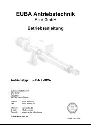
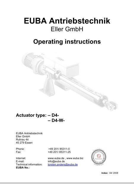
EUBA <strong>Antriebstechnik</strong><br />
<strong>Eller</strong> <strong>GmbH</strong><br />
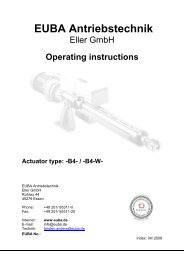
<strong>Operating</strong> instructions<br />
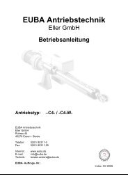
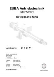
Actuator type: – <strong>D4</strong>-<br />
– <strong>D4</strong>-W-<br />
EUBA <strong>Antriebstechnik</strong><br />
<strong>Eller</strong> <strong>GmbH</strong><br />
Ruhrau 44<br />
45 279 Essen<br />
Phone: +49 201/ 85311-0<br />
Fax: +49 201/ 85311-25<br />
Internet: www.euba.de , www.euba.biz<br />
E-mail: info@euba.de<br />
Technical information: torsten.<strong>and</strong>ers@euba.de<br />
EUBA No.:<br />
Index: 04/ 2008
EUBA <strong>Antriebstechnik</strong><br />
<strong>Operating</strong> instructions for actuators types: -<strong>D4</strong>- <strong>and</strong> -<strong>D4</strong>-W-<br />
List of contents<br />
List of contents................................................................................................................................ 2<br />
1. Important Note ...................................................................................................................... 3<br />
1.1 Obligation <strong>and</strong> liability........................................................................................................ 3<br />
2. Security instructions ............................................................................................................... 4<br />
3. Actuator layout ....................................................................................................................... 5<br />
3.1 Basic layout........................................................................................................................ 5<br />
3.2 Type of protection .............................................................................................................. 5<br />
3.3 Designation of actuator type, name plate of the actuator.................................................. 5<br />
3.4 Designation of actuator type, name plate of the motor...................................................... 5<br />
4. Mechanical Assembly ............................................................................................................ 6<br />
4.1 Transport............................................................................................................................ 6<br />
4.2 Assembly ........................................................................................................................... 6<br />
5. Electrical installation............................................................................................................... 7<br />
5.1 Motor.................................................................................................................................. 7<br />
5.2 Actuator.............................................................................................................................. 7<br />
6. <strong>Operating</strong> Instructions ............................................................................................................ 8<br />
6.1 Setup of the overload switches.......................................................................................... 8<br />
6.2 EUBA way-limit-switches –WS …- .................................................................................... 9<br />
6.3 Programmable Current Loop Interface 4...20 mA (only type: <strong>D4</strong>-W) ............................. 11<br />
6.4 Potentiometer (0 … Ω) optional – only for type –<strong>D4</strong>-W- ................................................. 12<br />
7. Inspection und maintenance ................................................................................................ 13<br />
7.1 Maintenance instruction :................................................................................................. 13<br />
7.2 Lubrication instruction...................................................................................................... 13<br />
8. Operation <strong>and</strong> Service ......................................................................................................... 15<br />
9. Spare part list , type –<strong>D4</strong>- .................................................................................................... 16<br />
9.2 Spare parts drawing actuator type –<strong>D4</strong>- / -<strong>D4</strong>-W- ........................................................... 17<br />
10.1 Wiring diagram................................................................................................................. 19<br />
10.2 Sketch drawing ................................................................................................................ 19<br />
10.3 Technical Data Sheet ...................................................................................................... 20<br />
11. Storage instructions for long-term preservation............................................................... 21<br />
EUBA <strong>Operating</strong> instructions type -<strong>D4</strong>- / -<strong>D4</strong>-W- Page 2
EUBA <strong>Antriebstechnik</strong><br />
<strong>Operating</strong> instructions for actuators types: -<strong>D4</strong>- <strong>and</strong> -<strong>D4</strong>-W-<br />
1. Important Note<br />
Please mind in any case all security <strong>and</strong> warning instruction specified in this publication.<br />
Electrical hazard<br />
Possible consequences: Death or serious injury.<br />
Imminent danger<br />
Possible consequences: Death or serious injury.<br />
Dangerous situation<br />
Possible consequences: Slight or minor injury.<br />
Harmful situation<br />
Possible consequences: Damage to the unit <strong>and</strong> the environment.<br />
A requirement of fault-free operation <strong>and</strong> fulfillment of any rights to claim under guarantee is that the<br />
information in the operating instructions is adhered to.<br />
The operating <strong>manual</strong>s contain important advises about servicing; therefore keep it close to the<br />
actuator.<br />
1.1 Obligation <strong>and</strong> liability<br />
This operating <strong>manual</strong>, especially the safety instructions, are to be observed by all persons who work<br />
with or service the actuators. In addition to it the valid national / regional safety rules for each<br />
operating site <strong>and</strong> case are to be adhered to.<br />
The actuators are built according to established safety rules <strong>and</strong> state of engineering. Nevertheless<br />
severe or fatal injuries, impairments of the unit <strong>and</strong> the environment can happen due to inappropriate<br />
application. Therefore the running of the actuator is permitted only:<br />
if it meets the safety requirements, is in a flawless condition <strong>and</strong><br />
for appropriate application.<br />
Malfunctions which effect the safety are to be eliminated immediately.<br />
EUBA <strong>Operating</strong> instructions type -<strong>D4</strong>- / -<strong>D4</strong>-W- Page 3
to 1.1<br />
EUBA <strong>Antriebstechnik</strong><br />
<strong>Operating</strong> instructions for actuators types: -<strong>D4</strong>- <strong>and</strong> -<strong>D4</strong>-W-<br />
Basically our “general terms of sale <strong>and</strong> delivery“ are valid.<br />
Claims for guaranty <strong>and</strong> liability are excluded, if one or several of the following reasons can be traced<br />
to:<br />
inappropriate application,<br />
inappropriate mounting, startup <strong>and</strong> maintenance of the actuators,<br />
running of the actuators with defect safety appliances,<br />
non-observance of the operating instructions,<br />
unauthorized changes to the actuators,<br />
changes of actuating conditions (e.g. power <strong>and</strong> speed),<br />
inadequate control of wear-out parts <strong>and</strong><br />
unknown influences or force majeure.<br />
2. Security instructions<br />
The following security instructions are related to the use of the actuators.<br />
Please mind additional security instructions for motor <strong>and</strong> gear box in their corresponding operation<br />
<strong>manual</strong>s <strong>and</strong> also the supplementary security instructions in the individual chapters of this <strong>manual</strong>.<br />
Mounting, connection, startup, maintenance <strong>and</strong> repair only by trained personnel observing:<br />
these instructions,<br />
the warning <strong>and</strong> information signs on the motor / geared motor,<br />
all other project planning documents, operating instructions <strong>and</strong> wiring diagrams appertaining<br />
to the drive<br />
the specific regulations <strong>and</strong> requirements for the system <strong>and</strong><br />
currently valid national / regional regulations.<br />
These actuators are intended for industrial systems. They comply with the applicable st<strong>and</strong>ards <strong>and</strong><br />
regulations.<br />
Technical data <strong>and</strong> information about the permitted conditions where the actuator is used can be<br />
found on the name plate <strong>and</strong> in these operating instructions.<br />
It is essential for this specified information to be observed!<br />
EUBA <strong>Operating</strong> instructions type -<strong>D4</strong>- / -<strong>D4</strong>-W- Page 4
EUBA <strong>Antriebstechnik</strong><br />
<strong>Operating</strong> instructions for actuators types: -<strong>D4</strong>- <strong>and</strong> -<strong>D4</strong>-W-<br />
3. Actuator layout<br />
3.1 Basic layout<br />
Image 1<br />
The EUBA type –<strong>D4</strong>- / -<strong>D4</strong>-W- is an electro mechanical actuator with an acme thread spindle. The<br />
spindle is protected against environmental conditions by a push rod <strong>and</strong> is internally protected against<br />
twisting. The connection to an existing unit is done by a yoke end <strong>and</strong> bolt. All motors are DIN IEC<br />
norm-motors. All switches are easy accessible due to external switch boxes.<br />
3.2 Type of protection<br />
On request, EUBA actuators can be delivered with a type of protection from IP-54 to IP-67.<br />
St<strong>and</strong>ard type of protection: IP-55<br />
3.3 Designation of actuator type, name plate of the actuator<br />
-W- : Actuator with way limit switches (WS …)<br />
-<strong>D4</strong>- : Actuator type (size) –<strong>D4</strong>–<br />
The name plate of the actuator can be found on the casing. In addition, the actuator number is driven<br />
into the casing.<br />
Type : type of actuator<br />
Push Force (F) : Force push in daN<br />
Pull Force (F) : Force pull in daN<br />
No. : fabrication no. of the actuator<br />
S : stroke in mm<br />
v : velocity in mm/s.<br />
Image 2<br />
3.4 Designation of actuator type, name plate of the motor<br />
The specification on the name plate of the motors have to be met in any case.<br />
Please see operating instructions of the motor manufacturer.<br />
EUBA <strong>Operating</strong> instructions type -<strong>D4</strong>- / -<strong>D4</strong>-W- Page 5
EUBA <strong>Antriebstechnik</strong><br />
<strong>Operating</strong> instructions for actuators types: -<strong>D4</strong>- <strong>and</strong> -<strong>D4</strong>-W-<br />
4. Mechanical Assembly<br />
4.1 Transport<br />
Please mind the security instructions on page 4.<br />
For loading / unloading as well as mounting it is permitted only to use the below mentioned points of<br />
contact. As load support straps should be designated. The maximum permissible sloping position is<br />
30°. Only after a safe mounting of the EUBA-actuato r to the existing unit it is permitted to release the<br />
connection. Please take the single- / total weights from the sketch drawing. In individual cases the<br />
push rod is secured for transport.<br />
4.2 Assembly<br />
Before start-up of the actuator, please mind:<br />
Image 3<br />
• The EUBA actuator is equipped with a grease lubrication (see point 7). Please mind that no<br />
grease will flow out into the switchbox of the actuator through neither the opening of the<br />
overload-switches nor the opening of the way-limit-switches during the installation.<br />
• A horizontal installation of the actuator through which the switchbox is pointing<br />
downwards has to be avoided!<br />
• It is indispensable that the extending push rod is aligned properly with the fastening point.<br />
• Lateral stress on the push rod has to be avoided.<br />
• The actuator can be extended <strong>manual</strong>ly by turning the motor fan, but only in a current free<br />
state, therefore remove the protection cap of the motor.<br />
• It is possible to hinge the actuator into a steel construction by the welded-on pivot pin or to<br />
mount the actuator to a construction by using the EUBA-brackets, type –<strong>D4</strong>–.<br />
– brackets, type –<strong>D4</strong>-<br />
EUBA <strong>Operating</strong> instructions type -<strong>D4</strong>- / -<strong>D4</strong>-W- Page 6
EUBA <strong>Antriebstechnik</strong><br />
<strong>Operating</strong> instructions for actuators types: -<strong>D4</strong>- <strong>and</strong> -<strong>D4</strong>-W-<br />
5. Electrical installation<br />
Please consider the safety regulations on page 4.<br />
A startup of the actuators is permitted only after a complete electrical connection. For safety of the<br />
actuator it will be delivered with a slightly extended push rod so that a change of the motor rotation is<br />
possible.<br />
5.1 Motor<br />
5.2 Actuator<br />
Please mind the data on the name plate of the motor manufacturer <strong>and</strong><br />
the circuit diagram inside of the motor terminal box.<br />
Way limit switch box -WS …- (for actuators type W)<br />
Overload switches (DE) =S1 +S2<br />
Way limit switches (WS) S3 + S4<br />
S3 + S4 = one or bi-polar switches<br />
S1 = switching off for extending push rod<br />
S2 = switching off for retracting push rod<br />
Image 5<br />
EUBA <strong>Operating</strong> instructions type -<strong>D4</strong>- / -<strong>D4</strong>-W- Page 7
EUBA <strong>Antriebstechnik</strong><br />
<strong>Operating</strong> instructions for actuators types: -<strong>D4</strong>- <strong>and</strong> -<strong>D4</strong>-W-<br />
6. <strong>Operating</strong> Instructions<br />
Please consider the safety regulations on page 4.<br />
1. Keep the open connection boxes dry <strong>and</strong> dust free.<br />
2. Compare the main voltage with the voltage of the motor.<br />
3. Observe the phase sequence <strong>and</strong> direction of rotation.<br />
4. Before switching-on, the protection cap must be fitted to the motor again, to avoid the risk of<br />
accident.<br />
5. Connect overload switches S1 + S2 (Torque switches) according to the attached circuit<br />
diagram.<br />
Switch S1 = switching off for extending push rod<br />
Switch S2 = switching off for retracting push rod<br />
6. Stroke indicator switches S3 – S... have to be connected according to point 6.2 <strong>and</strong> to a<br />
special circuit diagram.<br />
7. Close the connection box. Examine gaskets <strong>and</strong> washers.<br />
8. Screw up the conduit fitting <strong>and</strong> secure it from dust <strong>and</strong> wetness.<br />
9. Adjust the thermal overcurrent release (bimetal) to the motor charging rate.<br />
10. For first operation, the .actuator should be switched on for a short time only <strong>and</strong> please mind<br />
point 7.<br />
11. Compare the direction of rotation with the push rod movement.<br />
Example: When switch S1 is actuated, it’s impossible to extend the push rod.<br />
6.1 Setup of the overload switches<br />
The EUBA-actuator, type –<strong>D4</strong>- / -<strong>D4</strong>-W- is factory-adjusted to the stipulated force<br />
between 4.500 daN <strong>and</strong> 15.000 daN before leaving our factory.<br />
It is permitted to change the setting of the overload switches because otherwise the<br />
actuator is damaged.<br />
EUBA <strong>Operating</strong> instructions type -<strong>D4</strong>- / -<strong>D4</strong>-W- Page 8
EUBA <strong>Antriebstechnik</strong><br />
<strong>Operating</strong> instructions for actuators types: -<strong>D4</strong>- <strong>and</strong> -<strong>D4</strong>-W-<br />
6.2 EUBA way-limit-switches –WS …-<br />
Bestelltext / Order text Getriebeendschalter<br />
Typ / Type KW 60 U1:1 L2<br />
Art. Nr. / Product-No. 9200.01.022<br />
Eingangsuntersetzung / Input ratios: 1:1 (Welle zu Schalter)<br />
Programmkanäle / Program channels L 2<br />
Verstellbare Einfachnockenscheibe / Cam wheel NK 3101.30° (Nockenerhöhung)<br />
Mikroschalter / Micro-switches: EUBA – Div. Schalter möglich / div. Switches possible<br />
Rückhol-Federmechanismus (Baukastensystem): wahlweise / optional<br />
Lose mitgeliefert / Including:<br />
Programmierschlüssel (schwarz) / Programme key (black) PSN<br />
Abbildung / Drawing:<br />
Programmieranleitung für Nockenscheiben / Programme instructions:<br />
Verstellbare Einfachnockenscheibe / Cam wheel NK 3101.30°<br />
Programmiermöglichkeiten / Programming possibilities<br />
Anzahl Impulse pro Umdrehung / Number of impulses per rotation: 1<br />
mit Nockenerhöhung 30° (Anschluss) / Impulse length 30° COM 1 - NO4<br />
Programmierschlüssel (schwarz) / Programme key (black) PSN<br />
The cam wheels/ discs can be programmed with the enclosed programme key (black) PSN. Insert the<br />
key in-between the desired nut <strong>and</strong> with a light sideways pressure on to the carrier the cam can be<br />
turned.<br />
EUBA <strong>Operating</strong> instructions type -<strong>D4</strong>- / -<strong>D4</strong>-W- Page 9
EUBA <strong>Antriebstechnik</strong><br />
<strong>Operating</strong> instructions for actuators types: -<strong>D4</strong>- <strong>and</strong> -<strong>D4</strong>-W-<br />
Montagehilfe<br />
Beispiel: Anbau - Einstellbare Stromschnittstelle (4...20mA) / Example for adding –DWG-<br />
Pos. 1 Mutter Spez. / Screw-nut Art. Nr. 5914.01.800<br />
2 Unterlegscheiben M3/ ring washer M3 0312.01.060<br />
3 Zylinderschraube mit Innensechskant M3 x 6 mm / hex key M 3x6 0304.11.171<br />
4 Getriebeendschalter (-WS …-) / WS-switch<br />
Optionen / Options:<br />
Rückholfeder (RF) Stromschnittstelle 2-Leiter 4-20mA Potentiometer<br />
- Drehwinkelgeber (DWG) (500 Ω , 1kΩ , 5 kΩ)<br />
Retaining spring (RF) Electronic-position-repeater (DWG) potentiometer<br />
(500 Ω , 1kΩ , 5 kΩ)<br />
EUBA <strong>Operating</strong> instructions type -<strong>D4</strong>- / -<strong>D4</strong>-W- Page 10
EUBA <strong>Antriebstechnik</strong><br />
<strong>Operating</strong> instructions for actuators types: -<strong>D4</strong>- <strong>and</strong> -<strong>D4</strong>-W-<br />
6.3 Programmable Current Loop Interface 4...20 mA (only type: <strong>D4</strong>-W)<br />
18..30 V<br />
DC<br />
(Two Wire Single Supply Powered)<br />
This unit produces a current ouput proportional to the setting of an externally connected<br />
potentiometer. Both the zero offset <strong>and</strong> slope of the output can independently programmed using the<br />
two on-board trimmer potentiometers.<br />
Specifications (Characterized at 24V Loop voltage)<br />
Power Supply: Loop Powered using the 4-20mA signal connection<br />
Loop Voltage: 18...30 V DC<br />
Current Consupmtion: 4...20 mA<br />
Power Consumption: 400 mW (maximum)<br />
External Burden Resistance: 1 kΩ (maximum with 24V or higher)<br />
Output Current (programmable): 4...20 mA<br />
Linearity: ± 0.5 %<br />
<strong>Operating</strong> Temperature Range: 0...70°C<br />
Temperature Dependence: 100 ppm/°C (maximum)<br />
Output Current Adjustent<br />
With the potentiometer being adjustable over a<br />
mechanical range of 0° to 330° the output current<br />
may be adjusted anywhere beween 4mA to 20mA<br />
inside the yellow shaded area as shown in the<br />
figure to the right.<br />
Min. Offset: 0°<br />
Max. Offset: 10°<br />
Min. Slope: 48.5 µA/°<br />
Max. Slope: 1.6 mA/°<br />
4..20<br />
mA<br />
0..1 kΩ<br />
The curve to the right visualizes the adjustment<br />
range which lies within the yellow shaded area.<br />
Potentiometer<br />
0..330°<br />
Programming Instructions:<br />
1. Set potentiometer to the desired lower limit (must be within 10° of maximum potentiometer<br />
deflection)<br />
2. Adjust the output to 4mA using the trimmer potentiometer labelled offset<br />
3. Set potentiometer to the desired upper maximum position<br />
4. Adjust the output to 20mA using the trimmer potentiometer labelled Span<br />
EUBA <strong>Operating</strong> instructions type -<strong>D4</strong>- / -<strong>D4</strong>-W- Page 11<br />
+<br />
0<br />
20 mA<br />
4 mA<br />
0 mA<br />
Offse<br />
t<br />
MR<br />
265<br />
Span<br />
Output Current<br />
Adjustment Range<br />
0° 10°<br />
330°
EUBA <strong>Antriebstechnik</strong><br />
<strong>Operating</strong> instructions for actuators types: -<strong>D4</strong>- <strong>and</strong> -<strong>D4</strong>-W-<br />
6.4 Potentiometer (0 … Ω) optional – only for type –<strong>D4</strong>-W-<br />
1 Gang-Feindrahtpotentiometer<br />
1 Turn-Wire-wound potentiometer<br />
• Widerst<strong>and</strong>werte 100R...100K (Ω)<br />
Resistance<br />
• Hohe Auflösung 0,1...0,02%<br />
Excellent linearity<br />
• Belastbarkeit 5W<br />
Power rating<br />
• Stapelbar 1...20<br />
Multi stocking<br />
Bestelltext How to order EUBA - 1 Gang-Feindrahtpotentiometer<br />
Widerst<strong>and</strong>wert / Auflösung Resistance / Resolution<br />
100R / 0,131% 1) 200R / 0,111% 500R / 0,083% 1K0 / 0,079% 2K0 / 0,076%<br />
5K0 / 0,059% 10K / 0,044%<br />
20K / 0,033% 1) 100K / 0,020% 1)<br />
1) auf Anfrage / On request<br />
Drehwinkel mech. / elektr. Rotation angle mech. / electr. 0...330° = 0...100%<br />
Widerst<strong>and</strong>stoleranz Resistance tolerance ±5 %<br />
Linearität Linearity
EUBA <strong>Antriebstechnik</strong><br />
<strong>Operating</strong> instructions for actuators types: -<strong>D4</strong>- <strong>and</strong> -<strong>D4</strong>-W-<br />
7. Inspection und maintenance<br />
7.1 Maintenance instruction :<br />
Image 7<br />
EUBA- actuators need a minimum maintenance.<br />
It’s limited to a regular control of the push rod (1) <strong>and</strong> spindle-, spindle-nut lubrication (2) only. The<br />
excess pressure valve (2a) prevents a superfattening.<br />
All inside parts as ball-, tapered roller-bearings, pressure- or cup-springs are “Long-Life“ lubricated.<br />
7.2 Lubrication instruction<br />
Push rod lubrication<br />
For relubrication please use the flat lubrication nippleM1 –DIN 3404 so that you get a light lubrication<br />
film on the push rod surface always.<br />
In exception the actuator can have an automatic lubricant transmitter or central lubricationwith less<br />
impulse time.<br />
Spindle-, spindle-nut-lubrication with grease excess pressure valve<br />
At work the EUBA-actuators have a normal first fill quantity of grease (see table 1). A relubrication<br />
should be done with the same grease (see table 2), but a lithium saponifiable grease without MOS 2 –<br />
additions (Symbol “K-P / 2-k”) can be used also.<br />
The best time for a relubrication fort his actuator types is after about 25.000 traversed strokes, but<br />
latest all 6 month. Extend the push rod approx. 50 mm before starting the lubrication process. For<br />
refilling quantities see table 1.<br />
Table 1: Grease quantity in gram<br />
First fillings acc. To (2) Refilling acc. to (2) for stroke up to mm First filling<br />
TYPES for 0 – Additional 100<br />
Acc. to (1)<br />
stroke mm stroke 500 750 1000 1250 1500 1750<br />
<strong>D4</strong> / <strong>D4</strong>-W 160 70 130 150 150 150 150 170 25<br />
EUBA <strong>Operating</strong> instructions type -<strong>D4</strong>- / -<strong>D4</strong>-W- Page 13
to 7.2<br />
EUBA <strong>Antriebstechnik</strong><br />
<strong>Operating</strong> instructions for actuators types: -<strong>D4</strong>- <strong>and</strong> -<strong>D4</strong>-W-<br />
In case of difficult site conditions such as damp, dustladen <strong>and</strong> aggressive surroundings, high or low<br />
temperature as well as a not passing of the complete stroke, refillings are necessary within a shorter<br />
period of time. The installed grease excess pressure valve (2a) prevents a superfattening of the<br />
spindle-, spindle-nut-area.<br />
Table 2: Analyze data for Paragon EP 1 Grease (DEA) Symbol KP1N–30<br />
Thickener of oil Lithium complex<br />
NLGI- Grade DIN 51818 1<br />
Base oil vis 40 0 C/100 0 C DIN 51562 mm 2 / s 170<br />
Dropping point min DIN-ISO 2176<br />
0 C 250<br />
Penetration DIN-ISO 2137 1 / 10 mm 310 / 340<br />
Pressure of fluidity at-35 0 C.<br />
Pressure of fluidity at +20<br />
DIN 51805 mbar 1100<br />
0 C. DIN 51805 mbar 100<br />
Emcor–Test DIN 51802 Degree of corrosion 0 / 0<br />
Corrosive effect to copper DIN 51811 0 - 150<br />
Oil seperation DIN 51817 g / 100 g 1 K / 4 N<br />
Working life : FAB - FE9 – test st<strong>and</strong><br />
At 150 0 C. / 6000 min -1 / 1500 N<br />
h<br />
100<br />
Change of hardness, Shore A Units<br />
-5<br />
Change of volume %<br />
+12<br />
Temperature range<br />
0 C -30 / +150<br />
Symbol DIN 51825 KP1N - 30<br />
Colour Green<br />
Alternative grease:<br />
Shell Alvania EP (LF) 1 – Lithium-12-Hydroxystearat<br />
In case you want to store the actuator for a certain period of time please ask for our long-term<br />
preservation (E-20).<br />
EUBA <strong>Operating</strong> instructions type -<strong>D4</strong>- / -<strong>D4</strong>-W- Page 14
EUBA <strong>Antriebstechnik</strong><br />
<strong>Operating</strong> instructions for actuators types: -<strong>D4</strong>- <strong>and</strong> -<strong>D4</strong>-W-<br />
8. Operation <strong>and</strong> Service<br />
Malfunction Possible cause Elimination<br />
actuator runs<br />
overload switches pos.<br />
209 doesn’t shut off<br />
motor runs in wrong sense of rotation<br />
mistake of overload-switch connections<br />
“forward” <strong>and</strong> “backward”<br />
Change 2 phases motor feeder resp.<br />
change connection of overload-switch<br />
pos. 209<br />
Motor doesn’t run Missing motor voltage Examine fuse<br />
Missing control voltage Examine reversing contractor<br />
Examine motor <strong>and</strong> pilot wire<br />
Motor starts up but<br />
disconnects immediately<br />
Motor starting with<br />
continuous switching on<br />
<strong>and</strong> off<br />
actuator seizes in<br />
endpoint position, locking<br />
of spindle pos. 11 <strong>and</strong><br />
spindle nut pos. 21<br />
actuator locks, motor<br />
disconnects with bi-metal<br />
<strong>and</strong> not with overload<br />
switch pos. 209<br />
Motor runs, push rod pos.<br />
23 doesn’t move “in” <strong>and</strong><br />
“out”<br />
push rod pos. 23 chatters<br />
when moving “in” or “out”<br />
actuator makes loud<br />
noises during running<br />
push rod can be moved in<br />
an axial direction by h<strong>and</strong><br />
actuator doesn’t move<br />
into end position<br />
Overload switch pos. 209 disconnects<br />
Load too large<br />
Starting torque too large<br />
Low-powered actuator<br />
Overload switches pos. 209 switches<br />
continuously<br />
Overload-switches pos. 209 are not<br />
connected resp. mistake of overload<br />
switch connections “forward” <strong>and</strong><br />
“backward”<br />
defect reversing contactor<br />
defect overload-switch pos. 209<br />
defect spindle bearing pos. 68<br />
defect coupling pos. 51 & 52<br />
defect spindle nut pos. 21<br />
not enough lubrication, worn out<br />
bushing guide pos. 42<br />
defect coupling pos. 51 & 52<br />
not enough lubrication<br />
defect spindle bearing pos. 68<br />
out of true push rod pos. 23 due to<br />
counter fixing<br />
worn out spindle nut pos .21, spindle<br />
nut pulled out of push rod pos. 23<br />
defect bearing pos. 68<br />
loose shaft nut pos. 69<br />
false design of actuator<br />
new determination of forces, consider<br />
acceleration due to enhancement of<br />
force<br />
please contact supplier<br />
better design of actuator<br />
abolish permanent contact<br />
move overload switches pos. 209 into<br />
holding circuit of contactor<br />
adjust overload switches only after<br />
contact with supplier (guarantee<br />
loss)<br />
connect overload switches pos. 209<br />
change connections of overload-switch<br />
replace overload-switches pos. 209<br />
exchange contactor<br />
exchange overload-switch pos. 209<br />
exchange bearing pos. 68<br />
dismount motor, exchange adjusting<br />
spring on engine shaft or spindle. For<br />
type “A2” dismount pin instead of<br />
adjusting spring, fix resp. exchange<br />
spindle nut pos. 21<br />
please relubricate, exchange bushing<br />
guide pos. 42, O-ring pos. 44 & scraper<br />
pos. 43 in lid pos. 41<br />
exchange coupling pos. 51 & 52<br />
please relubricate, exchange bearing<br />
pos. 68<br />
line out push rod pos.23 with<br />
counterpart<br />
exchange spindle nut pos. 21, fix<br />
spindle nut with push rod<br />
exchange bearing pos. 68<br />
tighten shaft nut pos. 69<br />
twisted push rod pos. 23 exchange push rod pos. 23<br />
EUBA <strong>Operating</strong> instructions type -<strong>D4</strong>- / -<strong>D4</strong>-W- Page 15
EUBA <strong>Antriebstechnik</strong><br />
<strong>Operating</strong> instructions for actuators types: -<strong>D4</strong>- <strong>and</strong> -<strong>D4</strong>-W-<br />
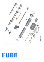
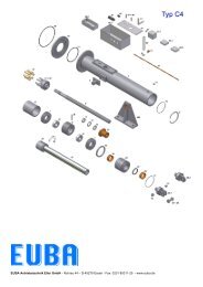
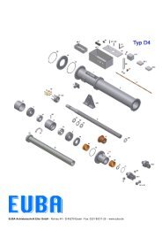
9. Spare part list , type –<strong>D4</strong>-<br />
Object Pc´s Bezeichnung Description<br />
1 1 Gehäuse Housing<br />
3 2 Drehzapfen Turning pin<br />
7 Satz Druckfeder / Tellerfeder Cup spring<br />
8 1 Spindel Acme thread spindle<br />
9 1 Lageraufnahme Bearing housing<br />
10* 2 Kegelrollenlager Tapered roller bearing<br />
11* 2 Nutmutter Shaft nut<br />
12* 1 Sicherungsblech Safety sheet<br />
14 + 33 2 Kupplung komplett Coupling<br />
15 Satz Kupplungspuffer Coupling buffer<br />
16 2 Druckring Thrust ring<br />
17 1 Distanzhülse Spacer sleeve<br />
18 1 Flansch Flange<br />
19 1 Schubrohr Push rod<br />
20 1 Spindelpuffer Acme thread spindle buffer<br />
21* 1 Flanschmutter Acme spindle nut<br />
22 1 Schubrohrkopf Push rod head<br />
23* 1 Drehstabführung Torsion rod guide<br />
25 1 Schubrohführung Push rod guide<br />
26* 2 Führungsbuchse Bushing guide<br />
27* 1 Abstreifer Scraper<br />
30.1 1 Gabelkopf Yoke end<br />
30.2 1 Gelenkauge mit Lager Shackle toggle joint<br />
31 1 Drehstab Torsion rod<br />
32 1 Überdrucksicherung Pressure safety<br />
34 + 35 1 Gabelkopfbolzen mit Scheiben Yoke end bolt + washer<br />
37 1 Winkel für Drehstab Angle for torsion rod<br />
38 1 Schaltbolzen Switching piece<br />
39* 1 O-Ring hinterer Flansch O-Ring rear flange<br />
40.1 1 Schaltkasten komplett Switch box complete<br />
Overload switch box<br />
40.2 1 Überlastschaltkasten<br />
complete<br />
42 1 Befestigungsplatte Mounting board<br />
44 2 Mikroschalterplatte Micro end switch board<br />
45* Satz Mikroschalter Micro end switches<br />
47+ 48 2 Abst<strong>and</strong>sbolzen mit Schiene Distance bolt + rail<br />
51 1 Winkel für Weganzeige Angle for way limit switch<br />
53.1 1 Weganzeige Way limit switch<br />
53.2 1 Potentiometer Potentiometer<br />
53.3 1 Stromschnittstelle 0/4…20 mA Electronic position transmitter<br />
66 1 Kettenrad Roller chain sprocket<br />
67 1 Kettenrad Roller chain sprocket<br />
68* 1 Rollenkette Roller chain<br />
71* 1 O-Ring Gabelkopf O-Ring yoke end<br />
72* 1 O-Ring Führungsbuchse O-Ring bushing guide<br />
73* 1 O-Ring vorderer Flansch O-Ring front flange<br />
74* 2 Schmiernippel Flat grease nipple<br />
400 2 Stehlager Brackets<br />
Parts that are marked with a (*) are wear out parts<br />
EUBA <strong>Operating</strong> instructions type -<strong>D4</strong>- / -<strong>D4</strong>-W- Page 16
EUBA <strong>Antriebstechnik</strong><br />
<strong>Operating</strong> instructions for actuators types: -<strong>D4</strong>- <strong>and</strong> -<strong>D4</strong>-W-<br />
9.2 Spare parts drawing actuator type –<strong>D4</strong>- / -<strong>D4</strong>-W-<br />
EUBA <strong>Operating</strong> instructions type -<strong>D4</strong>- / -<strong>D4</strong>-W- Page 17
EUBA <strong>Antriebstechnik</strong><br />
<strong>Operating</strong> instructions for actuators types: -<strong>D4</strong>- <strong>and</strong> -<strong>D4</strong>-W-<br />
to 9.2 switch box unit<br />
Photo – switch box:<br />
EUBA <strong>Operating</strong> instructions type -<strong>D4</strong>- / -<strong>D4</strong>-W- Page 18
EUBA <strong>Antriebstechnik</strong><br />
<strong>Operating</strong> instructions for actuators types: -<strong>D4</strong>- <strong>and</strong> -<strong>D4</strong>-W-<br />
10.1 Wiring diagram<br />
Dependent on order<br />
10.2 Sketch drawing<br />
Dependent on order<br />
EUBA <strong>Operating</strong> instructions type -<strong>D4</strong>- / -<strong>D4</strong>-W- Page 19
EUBA <strong>Antriebstechnik</strong><br />
<strong>Operating</strong> instructions for actuators types: -<strong>D4</strong>- <strong>and</strong> -<strong>D4</strong>-W-<br />
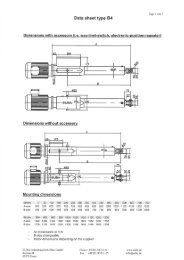
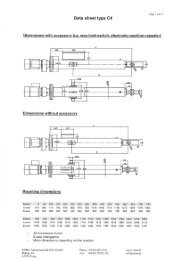
10.3 Technical Data Sheet<br />
Company:<br />
Order no.:<br />
EUBA No.:<br />
MECHANICAL : ELECTRICAL :<br />
Type : <strong>D4</strong>-W Drawing no. : E-<strong>D4</strong>- Three - phase - gear - motor :<br />
Force – pull – F : daN Product : Type :<br />
Force – push – F : daN Voltage – U : 230/ 400 V, Cycle – f : 0 Hz<br />
Stroke – s : 0 - mm Engine Power – P : kW, Type of construction:<br />
Velocity – v : mm/s Speed – n1 : min -1 , – n2 : min -1<br />
Mounting attachment : trunnion,<br />
yoke end with bolt<br />
Degree of protection – IP : 55 , Insulation class : F<br />
Fabrication no.: Rated current – IN : 0,6 A , IS/IR : about times<br />
Accessories : Wiring diagram no. :<br />
a)<br />
b)<br />
c)<br />
Date:<br />
Power factor : cos ϕ Efficiency : %<br />
Max. Temp : -10 - +60 0 C s/h : max. 30<br />
Circuit- opening of the micro-switches : 6A, by 230V AC<br />
EUBA <strong>Operating</strong> instructions type -<strong>D4</strong>- / -<strong>D4</strong>-W- Page 20
EUBA <strong>Antriebstechnik</strong><br />
<strong>Operating</strong> instructions for actuators types: -<strong>D4</strong>- <strong>and</strong> -<strong>D4</strong>-W-<br />
11. Storage instructions for long-term preservation<br />
If EUBA-Electric-Actuators are stored for a longer period of time before the start-up, an increasing protection<br />
from damage caused by corrosion or humidity can be achieved if the following instructions are observed.<br />
Please mind that the protective covering (actuators are shrink-packed with added humidity indicators) has to<br />
remain undamaged until installation of the actuators.<br />
We reserve the right of verification of the packing in order to accept the warranty agreed upon.<br />
Should the packing be damaged resp. be removed, as it occurs frequently, the following instructions have to<br />
be considered especially.<br />
Please mind that the above mentioned facts are also applicable when the actuators are well stored (well<br />
packed, dry <strong>and</strong> vibration free) for more than 2-3 years resp. beyond the agreed storage time.<br />
However, if the actuators are installed into a facility which is not due to start-up shortly, the actuators should<br />
be operated in short intervals. In any case the steps described as per point 3 need to be observed.<br />
The real operating conditions can be very strongly dependent on the local circumstances, therefore the times<br />
stated can only be considered as approximate values. These times do not include a prolongation of the<br />
warranty time.<br />
1. State of condition of EUBA-Electric-Actuators with mounted norm- resp. geared- motors as well<br />
as the storage room:<br />
1.1 Please check that all factory supplied plugs of the switch boxes are tightly fitted <strong>and</strong> that they<br />
are not damaged due to shipment. .If required please replace the damaged plugs.<br />
1.2 Shipment damages of the paint-work or the corrosion protection of the bare parts need to be<br />
repaired.<br />
1.3 If the environmental conditions differ from normal conditions of approx. -20°C to +40°C or<br />
varies often considerably, the steps described as per point 3 may become h<strong>and</strong>y even after<br />
shorter storage times.<br />
1.4 The storage room should be dry, ventilated <strong>and</strong> vibration-free.<br />
2. Precautions during storage time<br />
2.1 If the storage facilities allow so, we recommend a turning of 180° of the actuators every other<br />
year. This has to be considered especially for actuators with mounted gear-motors. These<br />
turnings ensure that the opposite gearwheels are lubricated again.<br />
2.2 The turning of the actuators can be cancelled if the gear box is completely filled up with<br />
lubricants on special agreement. For this case the lubricant level has to be reduced to its rated<br />
level according to the operating instructions <strong>and</strong> the lubrication plate before start-up. (Please<br />
see point 3.3.1)<br />
3. Precaution before start-up<br />
3.1 EUBA – Actuator unit<br />
3.1.1 Lubrication of the spindle bearings (Tapered-roller bearings).<br />
If the storage time exceeds 2-3 years or if both the temperatures <strong>and</strong> the humidity have been<br />
unfavourable for a time as per point 1.3, the lubricant of the EUBA-actuator has to be<br />
exchanged. Please consider the relevant instructions for precautions <strong>and</strong> lubrication<br />
recommendations.<br />
3.1.2 Lubrication of the spindle <strong>and</strong> the spindle-nut.<br />
These parts have been lubricated with a high-quality ex-works lubricant which however has to<br />
be exchanged as per point 3.1.1 too. Please observe the relevant instructions.<br />
EUBA <strong>Operating</strong> instructions type -<strong>D4</strong>- / -<strong>D4</strong>-W- Page 21
EUBA <strong>Antriebstechnik</strong><br />
<strong>Operating</strong> instructions for actuators types: -<strong>D4</strong>- <strong>and</strong> -<strong>D4</strong>-W-<br />
3.1.3 Lubrication of the push rod <strong>and</strong> the guiding bush<br />
The lubricant has to be renewed if the conditions correspond to those as per point 1.3.<br />
3.1.4 In connection with the exchange of the lubricant as per point 3.1.3, make sure also that the<br />
gaskets of the push-rod, i.e. the scraper <strong>and</strong> the O-ring work properly. If any changes in shape,<br />
colour, hardness or sealing effect are noticed, replace these parts immediately by observing<br />
the disassembly <strong>and</strong> assembly instructions.<br />
3.1.5 Check the built-in torque (DE) <strong>and</strong> stroke –indicator-switches (WE) with regard to their<br />
transition resistance.<br />
3.2 Motor unit<br />
3.2.1 Check of the insulation<br />
Please check the insulation resistance of the windings in combination of all winding parts as<br />
well as in combination with the housing <strong>and</strong> the windings by using a proper measuring device<br />
(e.g. a h<strong>and</strong> generator)<br />
Indicated value above 50 MΩ : No drying required. State of conditions as being new.<br />
Indicated value above 5 MΩ: Drying advisable.<br />
Indicated value about 1 MΩ : Lowest limit allowed.<br />
3.2.2 Drying of the windingsby heating the stator without disassembly.<br />
Connection to gradually or stepwise adjustable AC voltage up to max. 20% of the nominal<br />
voltage.<br />
Heating current max. 65 % of the nominal current as stated on the motor data plate.<br />
Observe heating process during the first 2-5 hours <strong>and</strong> reduce the heating voltage if required.<br />
Heating time approx. 12-24 hours so that the insulation resistance increases to its rated value<br />
again.<br />
3.2.3 Furnace drying of the windings after disassembly.<br />
Disassemble the motor properly.<br />
Dry the stator windings in a well ventilated drying furnace at +80°C to +100°C for approx. 12-24<br />
hours until the insulation resistance has reached ist stipulated rated value again.<br />
3.2.4 Lubrication of the rotor bearings.<br />
If the storage time exceeds some 2-3 years or if the temperatures have been very<br />
unfavourable during a shorter storage time as per point 1.3, please check the lubricant of the<br />
rotor bearings <strong>and</strong> exchange it if required. For this purpose it will be sufficient to disassemble<br />
the fan side of the motor partially. After removal of the fan cowl, fan <strong>and</strong> bearing flange the<br />
tapered-roller bearing will become visible.<br />
3.3 Gear unit (for geared-motors only)<br />
3.3.1 Lubricant<br />
If the storage time exceeds some 2-3 years or if the temperatures have been very<br />
unfavourable during a shorter storage time as per point 1.3, please check the lubricant of the<br />
gear box. Please consider the relevant instructions for precautions <strong>and</strong> lubrication<br />
recommendations.<br />
3.3.2 Shaft sealings<br />
In connection with the exchange of the lubricant please take into consideration that the shaft<br />
sealing between motor unit <strong>and</strong> gear unit as well as that of the motor shaft are working<br />
properly. If any changes in shape, colour, hardness or sealing effect are noticed, replace these<br />
parts immediately by observing the disassembly <strong>and</strong> assembly instructions.<br />
3.3.3 Sealants<br />
In case of any lubricant leaking at the mating surfaces of the gear unit, please renew the<br />
sealing compound immediately.<br />
EUBA <strong>Operating</strong> instructions type -<strong>D4</strong>- / -<strong>D4</strong>-W- Page 22