Katalog englisch.pmd - Euba-Antriebstechnik Eller GmbH
Katalog englisch.pmd - Euba-Antriebstechnik Eller GmbH
Katalog englisch.pmd - Euba-Antriebstechnik Eller GmbH

You also want an ePaper? Increase the reach of your titles
YUMPU automatically turns print PDFs into web optimized ePapers that Google loves.
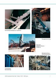
Bunker flap control in steel plant<br />
Flap actuator<br />
EUBA-<strong>Antriebstechnik</strong> <strong>Eller</strong> <strong>GmbH</strong> · P.O. Box 1432 07 · 45262 Essen<br />
Clarification plant<br />
Actuator for rake<br />
control<br />
Transfer mechanism<br />
Loading mechanism<br />
Lignite power plant<br />
1
Breeches chute actuator<br />
Throughlike edging guide<br />
for pig iron<br />
Governor level<br />
Belt scrapers<br />
for silos<br />
Actuator for slabbing<br />
alignment<br />
2 EUBA-<strong>Antriebstechnik</strong> <strong>Eller</strong> <strong>GmbH</strong> · P.O. Box 1432 07 · 45262 Essen
<strong>Antriebstechnik</strong><br />
<strong>Eller</strong> <strong>GmbH</strong><br />
Ruhrau 44<br />
D-45279 Essen<br />
P.O. Box 14 32 07<br />
D-45262 Essen<br />
Telephone +49/201/8 53 11 -0<br />
Telefax +49/201/8 53 11 -25<br />
E-Mail info@euba.de<br />
Internet www.euba.de<br />
We are certificated by<br />
Certificate-no. 5695<br />
Our supplies and services are based on our terms of business.<br />
Amendments of technical data as well as of measurements and weight, specified in this catalogue, are reserved.<br />
EUBA-<strong>Antriebstechnik</strong> <strong>Eller</strong> <strong>GmbH</strong> · P.O. Box 1432 07 · 45262 Essen<br />
General Description 4<br />
Attachment and Supplement 6<br />
Technical Explanation 7<br />
Survey of Products 9<br />
Typeleafs 10<br />
Piece Part Drawing and 22<br />
Spare Part Lists<br />
Special Actuators 26<br />
Wiring Diagrams 27<br />
Electronical Supplement 28<br />
Fax Request 29<br />
Special Features 30<br />
3
General Description<br />
EUBA - Over 40 years of Know-How in research<br />
and sale of electric actuators.<br />
Custom-made solutions are our strength.<br />
We offer actuators from minimum of 50 daN up to<br />
mega actuators with forces up to 200.000 daN.<br />
A qualified team of engineers advises you in case<br />
of actuating problems in situ.<br />
Innovative research and permanent quality control<br />
during manufacturing establishes standards. For<br />
your safety naturally no actuator leaves the factory<br />
until extensive examination.<br />
The actuators force can amount to 200.000 daN, with<br />
a stroke up to 7.000 mm and a variable velocity.<br />
Normally our actuators are manufactured with a hard<br />
chromium plated pushrod (special requests such as<br />
a ceramic plated pushrod can be considered).<br />
Commercial motor-gear combinations (A.C., D.C.,<br />
et al.), which are connected to the actuator by a DIN<br />
IEC flange, are used. Rotary actuators, which are able<br />
to do complete revolutions, can also be flanged.<br />
From the very first beginning of your project you will<br />
be supported by qualified employees.<br />
♦ Our engineering department also deals with<br />
special customer requests and offers solutions.<br />
♦ Since over 40 years we manufacture our<br />
actuators with constant quality.<br />
♦ Fast and professional assemblies will be done<br />
by our construction team.<br />
♦ We also take on the planning and installation of<br />
the complete control engineering.<br />
Profit by our Know-How, worldwide.<br />
The base conception of this actuator is approved in<br />
heavy industry (steel plants, power plants, cement<br />
plants, et al.).<br />
The actuator is made of a steel welded construction,<br />
sufficient dimensioned and equipped with the<br />
umpteen times proved EUBA overload switches.<br />
4 EUBA-<strong>Antriebstechnik</strong> <strong>Eller</strong> <strong>GmbH</strong> · P.O. Box 1432 07 · 45262 Essen
The advantages of the overload switches are:<br />
♦ protection of the actuators<br />
♦ absorption of axial impacts<br />
♦ pressure forces can be adjusted<br />
♦ wear-free attachment of motor and actuator<br />
(no slipping clutch).<br />
Overload switch unit<br />
In case of an overload of the requested push<br />
and pull forces, a shut-down of the actuator is<br />
guaranteed by overload switches.<br />
A demolition respectively an overload of the<br />
mechanical devices is excluded from the beginning.<br />
Due to external switch boxes the overload switches<br />
are easy accessible.<br />
With the use of different sets of springs it is possible<br />
to adjust the overload switch to several push and<br />
pull forces and thus to specific demands.<br />
EUBA-<strong>Antriebstechnik</strong> <strong>Eller</strong> <strong>GmbH</strong> · P.O. Box 1432 07 · 45262 Essen<br />
EUBA actuators can be equipped with auxiliary<br />
attachments,<br />
such as:<br />
♦ Separat way limit switches<br />
♦ Adjustable way limit switches for the whole<br />
stroke<br />
♦ Overload switches<br />
♦ Electronic position repeating devices 4 – 20 mA<br />
(continous)<br />
♦ Bus-compatible position controller (Profibus)<br />
♦ Frequency transformers<br />
overload switches<br />
bearing box<br />
set of<br />
springs<br />
spindle<br />
Due to the variability of the spring characteristics, as<br />
well as the travel of the spring system, the overload<br />
switch is able to absorb huge axial impacts.<br />
There is an optimal protection of the spindle against<br />
heavy loads, because the overload switch is<br />
integrated in the actuator itself.<br />
♦ Synchronization control for 2 or more actuators<br />
♦ Synchronous speed control for 2 or more<br />
actuators<br />
5
Attachment- and<br />
Auxiliary Supplement<br />
limit switch<br />
1- or 2- polar<br />
potentiometer<br />
electronic position<br />
transmitter<br />
baseplate threaded bold<br />
(external thread)<br />
brake motor<br />
way limit switch<br />
switch box<br />
incl.<br />
overload unit<br />
handwheel<br />
with or without electrical shutdown<br />
Yoke end<br />
shackle<br />
toggle joint<br />
gear motor<br />
angle joint with<br />
clamping head<br />
cardan joint<br />
bracket<br />
for pivot<br />
norm motor<br />
6 EUBA-<strong>Antriebstechnik</strong> <strong>Eller</strong> <strong>GmbH</strong> · P.O. Box 1432 07 · 45262 Essen
Technical Explanation<br />
Calculations:<br />
1. Determination of push-pull forces<br />
For the calculations of push-pull forces for EUBAactuators<br />
you have to consider the acceleration<br />
factors as specified in the chart below. This leads to<br />
the following calculation models:<br />
a) Horizontal movement b) Vertical movement<br />
F<br />
F<br />
B<br />
R<br />
F = F<br />
F B = acceleration force [N]<br />
m = body weight [kg]<br />
a = acceleration [m/s 2 ]<br />
G = load [N]<br />
g = gravitational force [m/s 2 ]<br />
F R = frictional force [N]<br />
µ = coefficient of friction<br />
F = neccessary force of EUBA-actuator [N]<br />
2. Acceleration factors<br />
According to the specific velocity you have to use<br />
the following acceleration factors as an average<br />
value:<br />
v [mm/s]<br />
a [m/s2 ]<br />
G<br />
= m⋅<br />
a = ⋅a<br />
g<br />
= µ ⋅G<br />
B<br />
+ F<br />
R<br />
F = FB<br />
+ FR<br />
+ G<br />
25 45 75 90 120 150 175 180<br />
1 2 3 4 5 6 7 8<br />
EUBA-<strong>Antriebstechnik</strong> <strong>Eller</strong> <strong>GmbH</strong> · P.O. Box 1432 07 · 45262 Essen<br />
3. Operating frequency<br />
The operating frequency (s/min) of the EUBAactuators<br />
depend on the maximum switching<br />
operations of the commercial motors and its<br />
electrical self-heating.<br />
Based on years of experience, the maximum<br />
operating frequency of the EUBA-actuators meets<br />
half of the maximum no-load switchings of the<br />
motor per minute.<br />
Hence we may infer the following average values :<br />
P [kW]<br />
s [1/min]<br />
P [kW]<br />
s [1/min]<br />
0,09 0,12 0,18 0,25 0,37 0,55 0,75<br />
35 35 30 25 25 20 20<br />
1,1 1,5 2,2 3 4 5,5 7,5<br />
18 15 15 10 8 6 6<br />
Above given data is meant for n=1500 min-1 maximum ambient temperature of t=40° C.<br />
and a<br />
The operating frequency depends on stroke and<br />
velocity also.<br />
Attention:<br />
A motor-switch over from a left-handed into a righthanded<br />
rotation or vice versa is not allowed without<br />
a shutdown of the motor itself.<br />
7
For special environmental and aggressive conditions<br />
EUBA-actuators can be sandblasted<br />
according to SA 2,5 and can be varnished with<br />
a coating thickness up to 240 µm.<br />
For the case the actuators are used in explosion<br />
hazardous plants, an application of way limit- and<br />
overload switches in Ex-i as well as three phase<br />
motors in the prescribed protection class is required.<br />
Protection class IP-55 is the standard of all EUBAactuators,<br />
but they are available up to protection<br />
class IP-68 on request.<br />
For an operation of the actuator during power failure<br />
we recommend a handwheel. For these actuators,<br />
the motor shaft protudes at the end. It is possible to<br />
equip the motor shaft with a handwheel or a crank.<br />
If demanded an electrical shutdown of the motor can<br />
be ensued when the handwheel is attached. The<br />
vacant second motor shaft is covered with a<br />
protection rod during normal operation all the time.<br />
Depending on the requirements EUBA-actuators<br />
are equipped with different lubricants. The specifications<br />
of the used lubricants can be found in the<br />
operation and maintenance manual.<br />
Usually the actuators are filled with Li-EP 2 grease.<br />
The maintenance of the EUBA-actuators is limited<br />
to regular relubrication of the spindle nut-system.<br />
An excess pressure protection impedes an overlubrication<br />
of the actuator.<br />
push rod lubrication<br />
relief valve<br />
spindle lubrication<br />
8 EUBA-<strong>Antriebstechnik</strong> <strong>Eller</strong> <strong>GmbH</strong> · P.O. Box 1432 07 · 45262 Essen
Survey of Products Standard Design<br />
EUBA-Typ<br />
* on request<br />
max.<br />
force<br />
F<br />
up<br />
to<br />
EUBA-<strong>Antriebstechnik</strong> <strong>Eller</strong> <strong>GmbH</strong> · P.O. Box 1432 07 · 45262 Essen<br />
max.<br />
velocity<br />
v<br />
up<br />
to<br />
max.<br />
stroke<br />
up<br />
to<br />
page<br />
A 4<br />
500 daN<br />
90mm/ s 600 mm<br />
10<br />
B 4<br />
2. 500<br />
daN<br />
180 mm/<br />
s 1. 250<br />
mm<br />
13<br />
C 4<br />
4. 500<br />
daN<br />
120 mm/<br />
s 2. 500<br />
mm<br />
16<br />
D 4<br />
15. 000<br />
daN<br />
60mm/ s 4. 000<br />
mm<br />
19<br />
E 4<br />
50. 000<br />
daN<br />
30mm/ s 4. 000<br />
mm<br />
30<br />
F 4*<br />
200. 000<br />
daN<br />
10mm/ s 4. 000<br />
mm<br />
30<br />
For the determination of forces, please consider calculations on page 7!<br />
9
Type A4:<br />
B-size changeable (+/- 100 mm)<br />
Mounting<br />
dimension<br />
actuator<br />
in<br />
mm<br />
( weight:<br />
25-35<br />
kg)<br />
stroke 0 50 100 150 200 250 300 350 400 450 500 550 600<br />
A-size 397 447 497 547 597 647 697 747 797 847 897 947 997<br />
B-size 206 256 306 356 406 456 506 576 626 676 726 776 826<br />
Actuator dimensions can vary, especially the motor dimensions due to different brands.<br />
Motor dimensions depending on motor type and supplier<br />
10 EUBA-<strong>Antriebstechnik</strong> <strong>Eller</strong> <strong>GmbH</strong> · P.O. Box 1432 07 · 45262 Essen
Power chart:<br />
F in<br />
daN<br />
Forces in between min. and max. can be realised continously.<br />
Standard design: - Pivot<br />
- Clevis<br />
Actuator: - Steel, with overload switches<br />
- Acme screw threat spindle<br />
- Spindle bearing system, on both sides supported by spring piles<br />
- Chrome plated push rod with internal torsion protection<br />
Motor: Attachment of DIN IEC flange- and gear motors<br />
Clevis:<br />
P in<br />
kW<br />
in<br />
accordance<br />
EUBA-<strong>Antriebstechnik</strong> <strong>Eller</strong> <strong>GmbH</strong> · P.O. Box 1432 07 · 45262 Essen<br />
with<br />
DIN<br />
IEC<br />
vinmm/ s<br />
5 25 45 63 70 94<br />
100 0, 09<br />
0, 12<br />
0, 18<br />
0, 18<br />
0, 25<br />
0,<br />
37<br />
200 0, 09<br />
0, 18<br />
0, 37<br />
0, 37<br />
0, 55<br />
0,<br />
55<br />
300 0, 09<br />
0, 25<br />
0, 55<br />
0, 55<br />
0, 75<br />
1,<br />
10<br />
400 0, 09<br />
0, 37<br />
0, 55<br />
0, 75<br />
1, 10<br />
1,<br />
10<br />
500 0, 12<br />
0, 37<br />
0, 75<br />
1, 10<br />
1, 10<br />
1,<br />
50<br />
Special design: - Brackets<br />
- Foot mounting<br />
- Cardan joint<br />
- Special fixing<br />
- Shackle toggle joint<br />
- Angle ball<br />
11
Cardan joint:<br />
Brackets for pivot:<br />
Shackle toggle joint:<br />
Please use Fax request sheet on page 29 for a detailed technical layout.<br />
Minor changes in dimensions are possible due to production tolerances.<br />
12 EUBA-<strong>Antriebstechnik</strong> <strong>Eller</strong> <strong>GmbH</strong> · P.O. Box 1432 07 · 45262 Essen
Type B4:<br />
B-size changeable (+/- 100 mm)<br />
Mounting<br />
dimension<br />
actuator<br />
in<br />
mm<br />
Motor dimensions depending on motor type and supplier<br />
EUBA-<strong>Antriebstechnik</strong> <strong>Eller</strong> <strong>GmbH</strong> · P.O. Box 1432 07 · 45262 Essen<br />
( weight:<br />
60-80<br />
kg)<br />
stroke 0 50 100 150 200 250 300 350 400 450 500 550 600<br />
A-size 502 552 602 652 702 752 802 852 902 952 1002 1052 1102<br />
B-size 308 358 408 458 508 558 608 658 708 758 808 858 908<br />
stroke 650 700 750 800 850 900 950 1000 1050 1100 1150 1200 1250<br />
A-size 1152 1202 1252 1302 1352 1402 1452 1502 1552 1602 1652 1702 1752<br />
B-size 958 1008 1058 1108 1158 1208 1258 1308 1358 1408 1458 1508 1558<br />
Actuator dimensions can vary, especially the motor dimensions due to different brands.<br />
13
Power chart:<br />
F in<br />
daN<br />
P in<br />
kW<br />
in<br />
accordance<br />
with<br />
DIN<br />
IEC<br />
vinmm/ s<br />
5 25 40 63 80 94 118<br />
500 0, 09<br />
0, 37<br />
0, 75<br />
1, 10<br />
1, 50<br />
1, 50<br />
2,<br />
20<br />
750 0, 12<br />
0, 55<br />
1, 10<br />
1, 50<br />
2, 20<br />
2, 20<br />
3,<br />
00<br />
1000 0, 18<br />
0, 75<br />
1, 50<br />
2, 20<br />
- 3, 00<br />
4,<br />
00<br />
1500 0, 25<br />
1, 10<br />
2, 20<br />
- - - -<br />
2000 0, 37<br />
1, 50<br />
3, 00<br />
- - - -<br />
2500 0, 37<br />
2, 20<br />
3, 00<br />
- - - -<br />
Forces in between min. and max. can be realised continously.<br />
Standard design: - Pivot<br />
- Clevis<br />
Actuator: - Steel, with overload switches<br />
- Acme screw threat spindle<br />
- Spindle bearing system, on both sides supported by spring piles<br />
- Chrome plated push rod with internal torsion protection<br />
Motor: Attachment of DIN IEC flange- and gear motors (manufacturer independent)<br />
Clevis:<br />
Special design: - Brackets<br />
- Foot mounting<br />
- Cardan joint<br />
- Special fixing<br />
- Shackle toggle joint<br />
- Angle ball<br />
14 EUBA-<strong>Antriebstechnik</strong> <strong>Eller</strong> <strong>GmbH</strong> · P.O. Box 1432 07 · 45262 Essen
Cardan joint:<br />
Brackets for pivot:<br />
Shackle toggle joint:<br />
Please use Fax request sheet on page 29 for a detailed technical layout.<br />
Minor changes in dimensions are possible due to production tolerances.<br />
EUBA-<strong>Antriebstechnik</strong> <strong>Eller</strong> <strong>GmbH</strong> · P.O. Box 1432 07 · 45262 Essen<br />
15
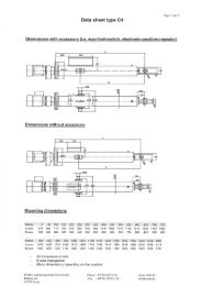
Type C4:<br />
Mounting<br />
dimension<br />
actuator<br />
in<br />
mm<br />
( weight:<br />
120-250<br />
kg)<br />
stroke 0 50 100 150 200 250 300 350 400 450 500 550 600 650 700 750<br />
A-size 618 668 718 768 818 868 918 968 1018 1068 1118 1168 1218 1268 1318 1368<br />
B-size 180 230 280 330 380 430 500 550 600 650 700 750 800 850 900 950<br />
stroke 800 850 900 950 1000 1050 1100 1150 1200 1250 1300 1350 1400 1450 1500<br />
A-size 1418 1468 1518 1568 1618 1668 1718 1768 1818 1868 1918 1968 2018 2068 2118<br />
B-size 1000 1050 1100 1150 1200 1250 1300 1350 1400 1450 1500 1550 1600 1650 1700<br />
Actuator dimensions can vary, especially the motor dimensions due to different brands.<br />
B-size changeable (+/- 100 mm)<br />
Motor dimensions depending on motor type and supplier<br />
16 EUBA-<strong>Antriebstechnik</strong> <strong>Eller</strong> <strong>GmbH</strong> · P.O. Box 1432 07 · 45262 Essen
Power chart:<br />
F in<br />
daN<br />
P in<br />
kW<br />
in<br />
accordance<br />
EUBA-<strong>Antriebstechnik</strong> <strong>Eller</strong> <strong>GmbH</strong> · P.O. Box 1432 07 · 45262 Essen<br />
with<br />
DIN<br />
IEC<br />
vinmm/ s<br />
5 15 25 35 45 111 166<br />
1500 0, 25<br />
0, 75<br />
1, 10<br />
2, 20<br />
2, 20<br />
5, 50<br />
7,<br />
50<br />
2000 0, 37<br />
1, 10<br />
1, 50<br />
2, 20<br />
3, 00<br />
- -<br />
2500 0, 55<br />
1, 50<br />
2, 20<br />
3, 00<br />
4, 00<br />
- -<br />
3000 0, 55<br />
1, 50<br />
3, 00<br />
4, 00<br />
4, 00<br />
- -<br />
4000 0, 75<br />
2, 20<br />
3, 00<br />
5, 50<br />
5, 50<br />
- -<br />
5000 0, 75<br />
3, 00<br />
4, 00<br />
5, 50<br />
7, 50<br />
- -<br />
Forces in between min. and max. can be realised continously.<br />
Standard design: - Pivot<br />
- Clevis<br />
Actuator: - Steel, with overload switches<br />
- Acme screw threat spindle<br />
- Spindle bearing system, on both sides supported by spring piles<br />
- Chrome plated push rod with internal torsion protection<br />
Motor: Attachment of DIN IEC flange- and gear motors (manufacturer independent)<br />
Clevis:<br />
Special design: - Brackets<br />
- Foot mounting<br />
- Special fixing<br />
- Shackle toggle joint<br />
- Angle ball<br />
17
Brackets for pivot:<br />
Shackle toggle joint:<br />
Please use Fax request sheet on page 29 for a detailed technical layout.<br />
Minor changes in dimensions are possible due to production tolerances.<br />
18 EUBA-<strong>Antriebstechnik</strong> <strong>Eller</strong> <strong>GmbH</strong> · P.O. Box 1432 07 · 45262 Essen
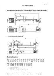
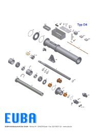
Type D4:<br />
Mounting<br />
dimension<br />
actuator<br />
in<br />
mm<br />
EUBA-<strong>Antriebstechnik</strong> <strong>Eller</strong> <strong>GmbH</strong> · P.O. Box 1432 07 · 45262 Essen<br />
( weight:<br />
150-400<br />
kg)<br />
stroke 0 50 100 150 200 250 300 350 400 450 500 550 600 650 700 750<br />
A-size 988 1038 1088 1138 1188 1238 1288 1338 1388 1438 1488 1538 1588 1638 1688 1738<br />
B-size 699 749 799 849 899 949 999 1049 1099 1149 1199 1249 1299 1349 1399 1449<br />
stroke 800 850 900 950 1000 1100 1200 1300 1400 1500 1600 1700 1800 1900 2000<br />
A-size 1788 1838 1888 1938 1988 2088 2188 2288 2388 2488 2588 2688 2788 2888 2988<br />
B-size 1499 1549 1599 1649 1699 1799 1899 1999 2099 2199 2299 2399 2499 2599 2699<br />
Actuator dimensions can vary, especially the motor dimensions due to different brands.<br />
B-size changeable (+/- 100 mm)<br />
Motor dimensions depending on motor type and supplier<br />
19
Power chart:<br />
F in<br />
daN<br />
P in<br />
kW<br />
in<br />
accordance<br />
with<br />
DIN<br />
IEC<br />
vinmm/ s<br />
5 15 25 35 40 50 60<br />
4000 0, 75<br />
2, 20<br />
4, 00<br />
5, 50<br />
7, 50<br />
7, 50<br />
9,<br />
20<br />
6000 1, 10<br />
4, 00<br />
5, 50<br />
7, 50<br />
9, 20<br />
11, 00<br />
15,<br />
00<br />
8000 1, 50<br />
5, 50<br />
7, 50<br />
11, 00<br />
15, 00<br />
15, 00<br />
18,<br />
50<br />
10000 2, 20<br />
5, 50<br />
9, 20<br />
15, 00<br />
15, 00<br />
18, 50<br />
22,<br />
00<br />
12500 2, 20<br />
7, 50<br />
11, 00<br />
18, 50<br />
18, 50<br />
22, 00<br />
30,<br />
00<br />
15000 3, 00<br />
9, 20<br />
15, 00<br />
18, 50<br />
22, 00<br />
30, 00<br />
-<br />
Forces in between min. and max. can be realised continously.<br />
Standard design: - Pivot<br />
- Clevis<br />
Actuator: - Steel, with overload switches<br />
- Acme screw threat spindle<br />
- Spindle bearing system, on both sides supported by spring piles<br />
- Chrome plated push rod with internal torsion protection<br />
Motor: Attachment of DIN IEC flange- and gear motors (manufacturer independent)<br />
Clevis:<br />
Special design: - Brackets<br />
- Foot mounting<br />
- Cardan joint<br />
- Special fixing<br />
- Shackle toggle joint<br />
- Angle ball<br />
20 EUBA-<strong>Antriebstechnik</strong> <strong>Eller</strong> <strong>GmbH</strong> · P.O. Box 1432 07 · 45262 Essen
Brackets for pivot:<br />
Shackle toggle joint:<br />
Please use Fax request sheet on page 29 for a detailed technical layout.<br />
Minor changes in dimensions are possible due to production tolerances.<br />
EUBA-<strong>Antriebstechnik</strong> <strong>Eller</strong> <strong>GmbH</strong> · P.O. Box 1432 07 · 45262 Essen<br />
21
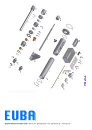
Spare parts drawing of EUBA-actuators<br />
Type A4<br />
Object Pc’s Description<br />
Object Pc’s Description<br />
1 1 Overload housing<br />
31 1 Torsion rod<br />
2 1 Rod housing<br />
32 1 Pressure safety<br />
3 2 Turning pin<br />
34 + 35 1 Yoke end bolt + washer<br />
6 1 Lock ring<br />
37 1 Angle for torsion rod<br />
7 Set Cup spring<br />
38 1 Switching piece<br />
8 1 Acme thread spindle<br />
39* 1 O-Ring rear flange<br />
9 1 Bearing housing<br />
40.1 1 Switch box complete<br />
10* 2 Tapered roller bearing<br />
40.2 1 Overload switch box complete<br />
11* 2 Shaft nut<br />
42 1 Mounting board<br />
12* 1 Safety sheet<br />
44 2 Micro end switch board<br />
14 + 33 2 Coupling<br />
45* Set Micro end switches<br />
16 2 Thrust ring<br />
47+ 48 2 Distance bolt + rail<br />
17 1 Spacer sleeve<br />
51 1 Angle for way limit switch<br />
18 1 Flange<br />
53.1 1 Way limit switch<br />
19 1 Push rod<br />
53.2 1 Potentiometer<br />
21* 1 Acme spindle nut<br />
53.3 1 Electronic position transmitter<br />
22 1 Push rod head<br />
66 1 Roller chain sprocket<br />
23* 1 Torsion rod guide<br />
67 1 Roller chain sprocket<br />
25 1 Push rod guide<br />
68* 1 Roller chain<br />
26* 2 Bushing guide<br />
71* 1 O-Ring joke end<br />
27* 1 Scraper<br />
72* 1 O-Ring bushing guide<br />
30.1 1 Yoke end<br />
73* 1 O-Ring front flange<br />
30.2 1 Shackle toggle joint<br />
74* 2 Flat grease nipple<br />
75 6 Spacer ring<br />
* = wear out parts<br />
400 2 Brackets<br />
Please indicate actuator number as well as the position of the spare part list.<br />
For online spare parts enquiries please go to www.euba.de<br />
22 EUBA-<strong>Antriebstechnik</strong> <strong>Eller</strong> <strong>GmbH</strong> · P.O. Box 1432 07 · 45262 Essen
Spare parts drawing of EUBA-actuators<br />
Type B4<br />
Object Pc’s Description<br />
1 1 Overload housing<br />
2 1 Rod housing<br />
3 2 Turning pin<br />
6 1 Lock ring<br />
7 Set Cup spring<br />
8 1 Acme thread spindle<br />
9 1 Bearing housing<br />
10* 2 Tapered roller bearing<br />
11* 2 Shaft nut<br />
12* 1 Safety sheet<br />
14 + 33 2 Coupling<br />
16 2 Thrust ring<br />
17 1 Spacer sleeve<br />
18 1 Flange<br />
19 1 Push rod<br />
21* 1 Acme spindle nut<br />
22 1 Push rod head<br />
23* 1 Torsion rod guide<br />
25 1 Push rod guide<br />
26* 2 Bushing guide<br />
27* 1 Scraper<br />
30.1 1 Yoke end<br />
30.2 1 Shackle toggle joint<br />
* = wear out parts<br />
Please indicate actuator number as well as the position of the spare part list.<br />
For online spare parts enquiries please go to www.euba.de<br />
EUBA-<strong>Antriebstechnik</strong> <strong>Eller</strong> <strong>GmbH</strong> · P.O. Box 1432 07 · 45262 Essen<br />
Object Pc’s Description<br />
31 1 Torsion rod<br />
32 1 Pressure safety<br />
34 + 35 1 Yoke end bolt + washer<br />
37 1 Angle for torsion rod<br />
38 1 Switching piece<br />
39* 1 O-Ring rear flange<br />
40.1 1 WS-Switch box complete<br />
40.2 1 Overload switch box complete (-DE-)<br />
42 1 Mounting board<br />
44 2 Micro end switch board<br />
45* Set Micro end switches<br />
47+ 48 2 Distance bolt + rail<br />
51 1 Angle for way limit switch<br />
53.1 1 Way limit switch -WS...-<br />
53.2 1 Potentiometer<br />
53.3 1 Electronic position transmitter (4/20 mA)<br />
66 1 Roller chain sprocket<br />
67 1 Roller chain sprocket<br />
68* 1 Roller chain<br />
71* 1 O-Ring yoke end<br />
72* 1 O-Ring bushing guide<br />
73* 1 O-Ring front flange<br />
74* 2 Flat grease nipple<br />
400 2 Brackets<br />
23
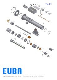
Spare parts drawing of EUBA-actuators<br />
Type C4<br />
Object Pc’s Description<br />
Object Pc’s Description<br />
1 1 Housing<br />
31 1 Torsion rod<br />
3 2 Turning pin<br />
32 1 Pressure safety<br />
6 1 Lock ring<br />
34 + 35 1 Yoke end bolt + washer<br />
7 Set Cup spring<br />
37 1 Angle for torsion rod<br />
8 1 Acme thread spindle<br />
38 1 Switching piece<br />
9 1 Bearing housing<br />
39* 1 O-Ring rear flange<br />
10* 2 Tapered roller bearing<br />
40.1 1 WS-Switch box complete<br />
11* 2 Shaft nut<br />
40.2 1 Overload switch box complete (-DE-)<br />
12* 1 Safety sheet<br />
42 1 Mounting board<br />
14 + 33 2 Coupling<br />
44 2 Micro end switch board<br />
15 Set Coupling buffer<br />
45* Set Micro end switches<br />
16 2 Thrust ring<br />
47+ 48 2 Distance bolt + rail<br />
17 1 Spacer sleeve<br />
51 1 Angle for way limit switch<br />
18 1 Flange<br />
53.1 1 Way limit switch<br />
19 1 Push rod<br />
53.2 1 Potentiometer<br />
21* 1 Acme spindle nut<br />
53.3 1 Electronic position transmitter (4/20 mA)<br />
22 1 Push rod head<br />
66 1 Roller chain sprocket<br />
23* 1 Torsion rod guide<br />
67 1 Roller chain sprocket<br />
25 1 Push rod guide<br />
68* 1 Roller chain<br />
26* 2 Bushing guide<br />
71* 1 O-Ring joke end<br />
27* 1 Scraper<br />
72* 1 O-Ring bushing guide<br />
30.1 1 Yoke end<br />
73* 1 O-Ring front flange<br />
30.2 1 Shackle toggle joint<br />
74* 2 Flat grease nipple<br />
400 2 Brackets<br />
* = wear out parts<br />
Please indicate actuator number as well as the position of the spare part list.<br />
For online spare parts enquiries please go to www.euba.de<br />
24 EUBA-<strong>Antriebstechnik</strong> <strong>Eller</strong> <strong>GmbH</strong> · P.O. Box 1432 07 · 45262 Essen
Spare parts drawing of EUBA-actuators<br />
Type D4<br />
Object Pc’s Description<br />
1 1 Housing<br />
3 2 Turning pin<br />
7 Set Cup spring<br />
8 1 Acme thread spindle<br />
9 1 Bearing housing<br />
10* 2 Tapered roller bearing<br />
11* 2 Shaft nut<br />
12* 1 Safety sheet<br />
14 + 33 2 Coupling<br />
15 Set Coupling buffer<br />
16 2 Thrust ring<br />
17 1 Spacer sleeve<br />
18 1 Flange<br />
19 1 Push rod<br />
20 1 Acme thread spindle buffer<br />
21* 1 Acme spindle nut<br />
22 1 Push rod head<br />
23* 1 Torsion rod guide<br />
25 1 Push rod guide<br />
26* 2 Bushing guide<br />
27* 1 Scraper<br />
30.1 1 Yoke end<br />
30.2 1 Shackle toggle joint<br />
* = wear out parts<br />
Please indicate actuator number as well as the position of the spare part list.<br />
For online spare parts enquiries please go to www.euba.de<br />
EUBA-<strong>Antriebstechnik</strong> <strong>Eller</strong> <strong>GmbH</strong> · P.O. Box 1432 07 · 45262 Essen<br />
Object Pc’s Description<br />
31 1 Torsion rod<br />
32 1 Pressure safety<br />
34 + 35 1 Yoke end bolt + washer<br />
37 1 Angle for torsion rod<br />
38 1 Switching piece<br />
39* 1 O-Ring rear flange<br />
40.1 1 Switch box complete<br />
40.2 1 Overload switch box complete<br />
42 1 Mounting board<br />
44 2 Micro end switch board<br />
45* Set Micro end switches<br />
47+ 48 2 Distance bolt + rail<br />
51 1 Angle for way limit switch<br />
53.1 1 Way limit switch<br />
53.2 1 Potentiometer<br />
53.3 1 Electronic position transmitter<br />
66 1 Roller chain sprocket<br />
67 1 Roller chain sprocket<br />
68* 1 Roller chain<br />
71* 1 O-Ring joke end<br />
72* 1 O-Ring bushing guide<br />
73* 1 O-Ring front flange<br />
74* 2 Flat grease nipple<br />
400 2 Brackets<br />
25
Special Actuators:<br />
Actuators type W:<br />
These actuators are specially designed for hydro engineering. The prescriptions of the<br />
DIN-standards for these actuators are realized by a special assembly.<br />
The range of application of our actuators are docks, flood gates, water works and purification<br />
plants (see page 32).<br />
Special designed actuators:<br />
Throughlike edging guide actuators:<br />
It is possible to adjust throughlike edging guides for all kinds with these actuators, e.g. for pig<br />
iron or slag. As a result high forces with small velocities can be fabricated also (see center<br />
page 2).<br />
Ingot pusher:<br />
Actuators of this kind can be used at industrial furnaces, foundry plants et al., where high<br />
forces, strokes and velocity are needed.<br />
Road blocker:<br />
Suitable for driveways, carparks or city entrances. The characteristic of this actuator is an<br />
automatic retraction during a power failure. Individual control panels, including key switches<br />
or remote controls for police-, fire departments and ambulances, for an automatic opening or<br />
closing for driveways can be installed (see page 31 down left).<br />
Gate actuators:<br />
Special designed actuators for opening and closing of heavy gates with long strokes.<br />
Strokes of 7 m can be realized with only one motor and two stroke units (see center<br />
page 31).<br />
Window actuators:<br />
With only one EUBA-actuator you are able to open and close columns of windows.<br />
Greenhouses, hangars, farmhouses or buildings with glass domes can be equiped with<br />
thermal sensors for an automatical control of the inside temperature.<br />
26 EUBA-<strong>Antriebstechnik</strong> <strong>Eller</strong> <strong>GmbH</strong> · P.O. Box 1432 07 · 45262 Essen
Wiring Diagrams<br />
Switches 1-polar<br />
1 2 3 4<br />
Switches 2-polar<br />
- standard- and breakmotors of all designs<br />
- gearmotors also<br />
way limit switches<br />
max. up to 6<br />
EUBA-<strong>Antriebstechnik</strong> <strong>Eller</strong> <strong>GmbH</strong> · P.O. Box 1432 07 · 45262 Essen<br />
Legend: HVE = Hand wheel with electrical switch off<br />
DE = Overload switch<br />
WS = Way limit switch<br />
POT = Potentiometer<br />
DWG = Electronical position repeater<br />
0-20 mA or 4-20 mA<br />
BL = Blinker unit<br />
HZ = Heater<br />
TW = Thermistor (PTC)<br />
MG = Transducer<br />
Special design:<br />
- Switches gold-plated<br />
- Initiators for shut-down<br />
- Position repeater 4...20 mA<br />
27
Electronical<br />
Supplement<br />
Way limit switches<br />
To indicate your<br />
desired position, we<br />
use a control system<br />
with two or more<br />
switches.<br />
Electronic position<br />
repeating devices<br />
We use electronic<br />
position repeating<br />
devices 0/4-20 mA as<br />
commercial, continous<br />
position indicators.<br />
Micro switch<br />
Special entire moulded<br />
switches ensure an<br />
ATEX-application.<br />
Plug connections<br />
For a fast assembly it<br />
is of great advantage to<br />
use plug connections<br />
of commercial<br />
manufactureres.<br />
Potentiometer<br />
It is possible to attach<br />
potentiometers for easy<br />
and profitable way<br />
indication.<br />
Frequency transformers<br />
Synchronization-, positioning controls and variable<br />
speed are possible by using frequency<br />
transformers.<br />
28 EUBA-<strong>Antriebstechnik</strong> <strong>Eller</strong> <strong>GmbH</strong> · P.O. Box 1432 07 · 45262 Essen
<strong>Antriebstechnik</strong><br />
<strong>Eller</strong> <strong>GmbH</strong><br />
Fax: +49 201- 8531125<br />
Fax Request<br />
EUBA-<strong>Antriebstechnik</strong> <strong>Eller</strong> <strong>GmbH</strong> · P.O. Box 1432 07 · 45262 Essen<br />
Company:<br />
Street:<br />
City:<br />
Country:<br />
Phone:<br />
Fax:<br />
Interlocutor:<br />
Regulating power dynamical: Fitting position:<br />
Pull: ...............daN<br />
Push: ...............daN<br />
Static stress: ...............daN<br />
Stroke: ...............mm Operating frequency: ...............s/h<br />
Velocity: ...............mm/s Cyclic duration factor: ................% ED<br />
Type of mounting:<br />
❑ bracket ❑ pivot ❑ clevis and bold<br />
❑ cardan joint ❑ flange ❑ shackle toggle joint+bearing<br />
❑ angle ball+socket joint ❑ special fixing (on request)<br />
Conditions of surroundings: Installation: Specification:<br />
❑ dusty ❑ outdoors ❑ high rust protection<br />
❑ humid ❑ rooved over ❑ special coating<br />
❑ tropic ❑ closed room ❑ bellow<br />
❑ sea surrounding ............... meter above sea level<br />
Connection voltage: 1AC ...............V ...............Hz DC ...............V<br />
3AC ......./.......V ...............Hz<br />
Enclosure: IP-....... Ambient temperature: ..........°C to ..........°C<br />
Insulation class: ...............<br />
Way limit switch:<br />
❑ 2 ❑ 4 ❑ 6 adjustable limit switches<br />
❑ potentiometer ...............Ω ❑ precision potentiometer ...............Ω<br />
❑ electronic position 0/4 - 20 mA ❑ special design (on request)<br />
transmitter<br />
Special design:<br />
❑ PTC thermistor sensor ❑ brake motor ❑ anti-condensation heater<br />
❑ switch box heater ❑ plug connection<br />
29
Special features<br />
Special actuators<br />
EUBA-elektro-actuators of series E4 and F4 are designed for forces up to<br />
2.000.000 N.<br />
Predominantly these actuators are produced for water engineering, iron and<br />
steel work et al.<br />
Explosion protection<br />
Our whole series of actuators can be produced for an operation in explosion-proof<br />
constructions zone 22, device category III.<br />
For this we will need detailed information about the job site.<br />
Synchronous working<br />
By controlling frequency inverters with the help of incremental-/absolute encoders<br />
a synchronous working of two or more actuators is ensured.<br />
30 EUBA-<strong>Antriebstechnik</strong> <strong>Eller</strong> <strong>GmbH</strong> · P.O. Box 1432 07 · 45262 Essen
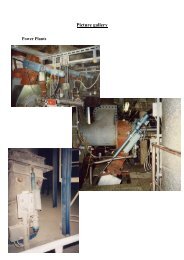
Road blocker<br />
Accessory drive<br />
smallest size<br />
EUBA-<strong>Antriebstechnik</strong> <strong>Eller</strong> <strong>GmbH</strong> · P.O. Box 1432 07 · 45262 Essen<br />
Test weight control for<br />
steel plant<br />
Gate actuator<br />
Force: 10 t, Stroke: 7000 mm<br />
Cab level regulation<br />
open-pit lignite mine<br />
31
Flood gate actuator<br />
Flood gate actuator<br />
Flood gate<br />
regulation<br />
Transfer mechanism<br />
steel-plant Krivoy-Rok<br />
Damper adjustment<br />
Silo feeding installation<br />
for belt conveyor system<br />
32 EUBA-<strong>Antriebstechnik</strong> <strong>Eller</strong> <strong>GmbH</strong> · P.O. Box 1432 07 · 45262 Essen