Health Informatics
Health Informatics
Health Informatics

You also want an ePaper? Increase the reach of your titles
YUMPU automatically turns print PDFs into web optimized ePapers that Google loves.
<strong>Health</strong> <strong>Informatics</strong><br />
(formerly Computers in <strong>Health</strong> Care)<br />
Kathryn J. Hannah Marion J. Ball<br />
Series Editors<br />
For other titles published in this series, go to<br />
www.springer.com/series/1114
Tim Benson<br />
Principles of <strong>Health</strong><br />
Interoperability HL7<br />
and SNOMED
Tim Benson<br />
www.abies.co.uk<br />
Thatcham RG 18 9WL<br />
UK<br />
ISBN 978-1-84882-802-5 e-ISBN 978-1-84882-803-2<br />
DOI 10.1007/978-1-84882-803-2<br />
Springer London Dordrecht Heidelberg New York<br />
British Library Cataloguing in Publication Data<br />
A catalogue record for this book is available from the British Library<br />
Library of Congress Control Number: 2009941467<br />
© Springer-Verlag London Limited 2010<br />
Apart from any fair dealing for the purposes of research or private study, or criticism or review, as<br />
permitted under the Copyright, Designs and Patents Act 1988, this publication may only be reproduced,<br />
stored or transmitted, in any form or by any means, with the prior permission in writing of the publishers,<br />
or in the case of reprographic reproduction in accordance with the terms of licenses issued by the<br />
Copyright Licensing Agency. Enquiries concerning reproduction outside those terms should be sent to<br />
the publishers.<br />
The use of registered names, trademarks, etc., in this publication does not imply, even in the absence of<br />
a specific statement, that such names are exempt from the relevant laws and regulations and therefore<br />
free for general use.<br />
The publisher makes no representation, express or implied, with regard to the accuracy of the information<br />
contained in this book and cannot accept any legal responsibility or liability for any errors or omissions that<br />
may be made.<br />
Printed on acid-free paper<br />
Springer is part of Springer Science+Business Media (www.springer.com)
This book is dedicated to my sons<br />
Laurence, Oliver, Alex and Jamie.
Foreword<br />
<strong>Health</strong> data standards are a necessary component for interoperability in health care.<br />
Aggregation of health-related data mandates the use of standards, and aggregation<br />
is necessary to support safe and quality care. The American Recovery and<br />
Reinvestment Act (ARRA) includes $19 billion in direct funding and an additional<br />
$18.5 billion in returned savings tagged to the use of health information technology<br />
(HIT). The resulting expanding use of HIT has engaged a growing number of stakeholders,<br />
many of whom are now realizing the value of standards.<br />
All aspects of the process of creating and effectively using electronic health<br />
records (EHRs), which meet the requirements of “meaningful use,” require standards.<br />
From the planning stages of effective use of HIT through reference information<br />
models, data models, use cases, story boards, and domain analysis models; to<br />
defining the data elements with common terminologies, definitions, data types,<br />
units and other attributes; to templates, clinical statements, clinical documents and<br />
data interchange; and to the EHR, its functional requirements in multiple sites and<br />
presentations; to decision support standards; and including standards for security<br />
and privacy. These standards extend beyond definition standards, to use standards<br />
for linkage among disparate systems to standards for reports (claims, infectious<br />
disease reports, patient summaries).<br />
With the increasing demand for individuals knowledgeable in what standards are<br />
available and when and how to use those standards, this book is most welcome. The<br />
author, Tim Benson, has been engaged in the creation of standards since the beginning.<br />
His experiences span organizations – including HL7, CEN, and ISO, and<br />
terminologies such as SNOMED and LOINC. He has engaged the global community<br />
and understands similarities as well as differences among the global community.<br />
He has a top reputation as a teacher and writer within the international<br />
community. I know no other individual who is more qualified to write this book<br />
than Tim Benson.<br />
In Principles of <strong>Health</strong>care Interoperability HL7 and SNOMED, Tim focuses on<br />
major contributors to the set of required standards. In the first section, he lays out<br />
a framework for why interoperability is important and what is needed to accomplish<br />
that interoperability. Although there are several contributing Standards<br />
Developing Organizations (SDOs) in the global community, <strong>Health</strong> Level Seven is<br />
perhaps preeminent. Its standards are widely used, and cover the full spectrum of<br />
vii
viii Foreword<br />
applications. Its membership is international (currently including over 35 countries)<br />
and includes the major HIT vendors and representatives of the full set of stakeholders.<br />
The International <strong>Health</strong>care Technology Standards Developing Organization<br />
(IHTSDO) is rapidly promoting SNOMED CT as the preferred terminology in<br />
health care. But at the same time, while focusing on HL7 and SNOMED CT, he<br />
includes much useful information on other standards and other organizations.<br />
Readers will find this book easy to read, even if it is their first exposure to standards.<br />
In this rapidly changing field, this book is a must for anyone who is involved<br />
or has interest in the use of health information technology – and who is not.<br />
W. Ed Hammond, Ph.D.<br />
Professor Emeritus, Department of Community<br />
and Family Medicine, School of Medicine<br />
Professor Emeritus,<br />
Department of Biomedical Engineer,<br />
Pratt School of Engineering<br />
Adjunct Professor,<br />
Fuqua School of Medicine<br />
Duke University,<br />
Durham North Carolina<br />
Founding Member of <strong>Health</strong> Level<br />
Seven (1987)Chair, HL7 (1991, 1996-1997,2008-2009)
Preface<br />
<strong>Health</strong> care has to cross the quality chasm, to become safer, more efficient and<br />
effective (Institute of Medicine 2001). The transformation of health care depends<br />
critically on interoperability, enabling computers to share information and deliver<br />
information from where it originates to where it is needed.<br />
When interoperability is commonplace, patients, clinicians, managers, and<br />
researchers will enjoy secure access to the right information at the right time and<br />
the at right place; they will make more soundly based decisions, leading to better<br />
patient outcomes and fewer mistakes. Interoperability is a prerequisite for the process<br />
reengineering that will reduce the waste of unnecessary costs, errors, delays,<br />
and futile repetition.<br />
There is nothing new in this (Blum and Duncan 1990; Hayes and Barnett 2008).<br />
Why has it not happened? At a technical level it cannot take place until we agree,<br />
implement, and deploy the sort of stringent standards that are needed for plug and<br />
play between the disparate computer systems found in health care.<br />
These standards will almost certainly be based on HL7 and SNOMED CT working<br />
together as a tightly specified language for exchanging health-care information.<br />
All languages depend on grammar and words. HL7 provides the grammar as standardized<br />
structures for healthcare communication, rather like English or French<br />
grammar, while SNOMED CT provides a comprehensive clinical terminology,<br />
analogous to a dictionary.<br />
The documentation of HL7 and SNOMED runs to tens of thousands of pages and<br />
creates a steep learning curve and barrier for entry. This book sets out to provide an<br />
introduction to these standards, focusing on the core principles in a way that is understandable<br />
to the average analyst, student, clinician and manager.<br />
ix
About the Author<br />
Tim Benson graduated from the University of Nottingham as a mechanical engineer,<br />
was introduced to health-care computing at the Charing Cross Hospital in<br />
London (now part of the Imperial College <strong>Health</strong>care NHS Trust), where he evaluated<br />
the socioeconomic benefits of medical computing systems. In 1980, he<br />
founded Abies <strong>Informatics</strong>, Ltd. as one of the first GP computer suppliers. There,<br />
he needed a coding system to record consultation details and, with James Read and<br />
David Markwell, developed a proprietary system, which became known as the<br />
Read Codes. In 1987, a working party set up by the British Medical Association<br />
and the Royal College of General Practitioners recommended that this become a<br />
national standard in the UK and it went on to become one of the two main tributaries<br />
of SNOMED CT. In 1988, he was invited to lead a European project team to<br />
examine the need for open standards in health informatics, which led to 2 decades<br />
of work on interoperability standards and collaboration with HL7.<br />
Tim is founder of Abies Ltd. and Routine <strong>Health</strong> Outcomes Ltd. He is an honorary<br />
Senior Research Fellow at UCL CHIME (Centre of <strong>Health</strong> <strong>Informatics</strong> and<br />
Multi-professional Education).<br />
xi
Acknowledgments<br />
Many people have contributed to my understanding of health-care interoperability,<br />
HL7 and SNOMED. First, I want to single out David Markwell, my friend and collaborator<br />
for 25 years, who has made an enormous personal contribution to both<br />
clinical terminology and health-care interoperability. In the HL7 space, I want to<br />
acknowledge my debt to Ed Hammond, Mark Schafarman, Jack Harrington, Clem<br />
McDonald, Woody Beeler, Charlie Mead, and Bob Dolin. I also want to acknowledge<br />
the members of the HL7 Education Committee including Mike Henderson,<br />
Abdul-Malik Shakir, Virginia Lorenzi, and Rene Spronk, and members of HL7 UK,<br />
notably Charlie McCay, Leo Fogarty, Andrew Hinchley, Martin Whittaker, and Ann<br />
Wrightson. In clinical terminology I have learnt much from Alan Rector, Kent<br />
Spackman, Ed Cheetham, and Tom Marley. I would also like to thank Roddy<br />
Neame, Sigurd From, Georges de Moor, Seref Arikan, and David Ingram.<br />
xiii
Series Preface<br />
This series is directed to <strong>Health</strong>-care professionals, who are leading the transformation<br />
of health care by using information and knowledge. Historically, the series was<br />
launched in 1988 as Computers in <strong>Health</strong> Care, to offer a broad range of titles:<br />
some addressed to specific professions such as nursing, medicine, and health<br />
administration; others to special areas of practice such as trauma and radiology; still<br />
other books in the series focused on interdisciplinary issues, such as the computerbased<br />
patient record, electronic health records, and networked health-care systems.<br />
Renamed <strong>Health</strong> <strong>Informatics</strong> in 1998 to reflect the rapid evolution in the discipline<br />
known as health <strong>Informatics</strong>, the series continued to add titles that contribute to the<br />
evolution of the field. In the series, eminent experts, serving as editors or authors,<br />
offer their accounts of innovations in health <strong>Informatics</strong>. Increasingly, these<br />
accounts go beyond hardware and software to address the role of information in<br />
influencing the transformation of <strong>Health</strong>-care delivery systems around the world.<br />
The series also increasingly focused on the users of the information and systems:<br />
the organizational, behavioral, and societal changes that accompany the diffusion<br />
of information technology in health services environments.<br />
Developments in health-care delivery are constant; most recently developments<br />
in proteomics and genomics are increasingly becoming relevant to clinical decision<br />
making and emerging standards of care. The data resources emerging from molecular<br />
biology are beyond the capacity of the human brain to integrate and beyond the<br />
scope of paper-based decision trees. Thus, bioinformatics has emerged as a new<br />
field in health informatics to support emerging and ongoing developments in<br />
molecular biology. Translational informatics supports acceleration, from bench to<br />
bedside, i.e., the appropriate use of molecular biology research findings and bioinformatics<br />
in clinical care of patients.<br />
At the same time, further continual evolution of the field of <strong>Health</strong> informatics<br />
is reflected in the introduction of concepts at the macro or health systems delivery<br />
level with major national initiatives related to electronic health records (EHR), data<br />
standards and public health informatics such as the <strong>Health</strong>care Information<br />
Technology Standards Panel (HITSP) in the USA, Canada <strong>Health</strong> Infoway, NHS<br />
Connecting for <strong>Health</strong> in the UK.<br />
We have consciously retained the series title <strong>Health</strong> <strong>Informatics</strong> as the single<br />
umbrella term that encompasses both the microscopic elements of bioinformatics<br />
xv
xvi Series Preface<br />
and the macroscopic aspects of large national health information systems. Ongoing<br />
changes to both the micro and the macro perspectives on health informatics will<br />
continue to shape health services in the Twenty First Century. By making full and<br />
creative use of the technology to tame data and to transform information, health<br />
<strong>Informatics</strong> will foster the development and use of new knowledge in health care.<br />
As coeditors, we pledge to support our professional colleagues and the series readers<br />
as they share advances in the emerging and exciting field of <strong>Health</strong><br />
<strong>Informatics</strong>.<br />
Kathryn J. Hannah<br />
Marion J. Ball
Contents<br />
Part I Principles of Interoperability<br />
1 The <strong>Health</strong> Information Revolution ........................................................ 3<br />
1.1 <strong>Health</strong> Care is Communication .......................................................... 6<br />
1.2 Patient-Centric <strong>Health</strong> Care ............................................................... 8<br />
1.3 Stages of Information Handling ......................................................... 9<br />
1.4 <strong>Health</strong> Care is Complex ..................................................................... 12<br />
1.5 Looking Back ..................................................................................... 13<br />
1.5.1 Problem-Oriented Medical Records ....................................... 14<br />
1.5.2 El Camino Hospital Project .................................................... 15<br />
1.5.3 The NHS National Programme for IT .................................... 16<br />
1.5.4 Lessons from Denmark .......................................................... 17<br />
1.6 Evidence-Based Medicine ................................................................. 19<br />
1.7 EHR System Functional Model ......................................................... 20<br />
2 Why Interoperability is Hard .................................................................. 25<br />
2.1 What is Interoperability? .................................................................... 25<br />
2.2 Benefits .............................................................................................. 26<br />
2.3 Need for a Lingua Franca .................................................................. 28<br />
2.4 Electronic <strong>Health</strong> Records ................................................................. 28<br />
2.5 Analysis is Paramount ........................................................................ 31<br />
2.6 Complex Specifications Create Errors ............................................... 32<br />
2.7 Users and Suppliers are both Guilty .................................................. 33<br />
2.8 Shared Meaning ................................................................................. 33<br />
3 Models ........................................................................................................ 35<br />
3.1 Modeling Basics ................................................................................. 35<br />
3.1.1 Model Driven Architecture .................................................... 36<br />
3.1.2 The CEN Model ..................................................................... 36<br />
3.1.3 Modeling Maturity ................................................................. 37<br />
3.2 Life Cycle ........................................................................................... 39<br />
3.3 Preliminary Business Analysis .......................................................... 39<br />
3.3.1 Scope ...................................................................................... 40<br />
xvii
xviii Contents<br />
3.3.2 Storyboard .............................................................................. 41<br />
3.3.3 Business Analysis .................................................................. 42<br />
3.3.4 Glossary ................................................................................. 44<br />
3.4 Conceptual Design ............................................................................. 44<br />
3.4.1 Criteria ................................................................................... 45<br />
3.4.2 Technology-Specific Design .................................................. 48<br />
3.5 Colorectal Cancer Referral ................................................................ 48<br />
3.5.1 Scope and Background ........................................................... 48<br />
3.5.2 Objectives ............................................................................... 49<br />
3.5.3 Participants and Locations ..................................................... 49<br />
3.5.4 Outcome ................................................................................. 50<br />
3.5.5 Storyboard .............................................................................. 50<br />
3.5.6 Business Process Diagram ..................................................... 51<br />
3.5.7 Data and Rules ....................................................................... 51<br />
4 UML and XML ......................................................................................... 55<br />
4.1 Unified Modeling Language .............................................................. 55<br />
4.1.1 UML Diagrams ...................................................................... 56<br />
4.2 Structure Diagrams ............................................................................ 58<br />
4.2.1 Class Diagrams ...................................................................... 58<br />
4.2.2 Package .................................................................................. 61<br />
4.2.3 Deployment ............................................................................ 61<br />
4.3 Modeling Behavior ............................................................................ 62<br />
4.3.1 Use Case ................................................................................. 62<br />
4.3.2 Activity Diagram .................................................................... 63<br />
4.3.3 Sequence Diagram ................................................................. 65<br />
4.3.4 Statechart Diagram ................................................................. 65<br />
4.4 UML Summary .................................................................................. 66<br />
4.5 Business Process Modeling Notation (BPMN) .................................. 67<br />
4.5.1 Activities ................................................................................ 67<br />
4.5.2 Business Process Example ..................................................... 69<br />
4.6 XML ................................................................................................... 69<br />
4.6.1 Markup ................................................................................... 71<br />
4.6.2 Descriptive and Procedural Markup ....................................... 71<br />
4.6.3 XML Files .............................................................................. 71<br />
4.6.4 XML Schema ......................................................................... 72<br />
4.6.5 XML Element ........................................................................ 72<br />
4.6.6 XML Attribute ....................................................................... 73<br />
4.6.7 Entity ...................................................................................... 73<br />
4.6.8 Namespace ............................................................................. 73<br />
4.6.9 The XML Family ................................................................... 73<br />
5 Standards Development Organizations .................................................. 75<br />
5.1 What is a Standard? ........................................................................... 75<br />
5.2 International Standards Development Organizations (SDOs) ........... 76<br />
5.3 <strong>Health</strong> Level Seven ............................................................................ 78
Contents<br />
5.3.1 What Does the Name HL7 Mean? ......................................... 79<br />
5.3.2 HL7 Products ......................................................................... 80<br />
5.3.3 Ballot Process ......................................................................... 80<br />
5.3.4 Language ................................................................................ 80<br />
5.3.5 Membership ........................................................................... 81<br />
5.3.6 International Affiliates ........................................................... 81<br />
5.3.7 The Technical Steering Committee ........................................ 81<br />
5.4 Other SDOs and Consortia ................................................................. 83<br />
5.4.1 IHTSDO ................................................................................. 83<br />
5.4.2 IHE ......................................................................................... 84<br />
5.4.3 Continua Alliance .................................................................. 85<br />
5.4.4 OpenEHR ............................................................................... 85<br />
5.4.5 Open <strong>Health</strong> Tools .................................................................. 86<br />
5.4.6 CDISC .................................................................................... 87<br />
Part II HL7 – <strong>Health</strong> Level Seven<br />
6 HL7 Version 2 ............................................................................................ 91<br />
6.1 Message Syntax ................................................................................. 92<br />
6.1.1 Delimiters ............................................................................... 95<br />
6.2 Segment Definition ............................................................................ 96<br />
6.2.1 Message Header MSH............................................................ 97<br />
6.2.2 Patient Identification Details (PID) ........................................ 98<br />
6.2.3 Patent Visit (PV1) .................................................................. 99<br />
6.2.4 Request and Specimen Details (OBR) ................................... 100<br />
6.2.5 Result Details (OBX) ............................................................. 100<br />
6.2.6 Z-Segments ............................................................................ 101<br />
6.3 Data Types .......................................................................................... 101<br />
6.3.1 Simple Data Types ................................................................. 103<br />
6.3.2 Complex Data Types .............................................................. 103<br />
6.3.3 Codes and Identifiers .............................................................. 103<br />
6.3.4 Names and Addresses ............................................................ 105<br />
6.3.5 Other Complex Data Types .................................................... 105<br />
6.4 A Simple Example ............................................................................. 105<br />
7 The HL7 V3 RIM ...................................................................................... 107<br />
7.1 Origins ................................................................................................ 107<br />
7.2 Overview ............................................................................................ 108<br />
7.3 The RIM Backbone ............................................................................ 109<br />
7.3.1 Structural Attributes ............................................................... 109<br />
7.3.2 Specializations ....................................................................... 112<br />
7.4 Act ...................................................................................................... 113<br />
7.4.1 Act classCode ......................................................................... 113<br />
7.4.2 moodCode .............................................................................. 113<br />
7.4.3 StatusCode ............................................................................. 114<br />
7.4.4 Times ...................................................................................... 114<br />
xix
xx Contents<br />
7.4.5 Act Specializations............................................................... 115<br />
7.5 Entity ................................................................................................ 118<br />
7.5.1 Entity Specializations........................................................... 118<br />
7.6 Role .................................................................................................. 119<br />
7.6.1 Role Specializations ............................................................. 120<br />
7.7 Association Classes .......................................................................... 120<br />
7.7.1 ActRelationship.................................................................... 120<br />
7.7.2 Participation ......................................................................... 120<br />
7.7.3 Role Link ............................................................................. 122<br />
7.8 HL7 Version 3 Data Types ............................................................... 122<br />
7.8.1 Basic Data Types .................................................................. 122<br />
7.8.2 Codes and Identifiers ........................................................... 122<br />
7.8.3 Date/Time ............................................................................. 124<br />
7.8.4 Name and Address ............................................................... 125<br />
7.8.5 Generic Collections .............................................................. 125<br />
7.9 Communication Infrastructure ......................................................... 125<br />
7.9.1 Infrastructure Root ............................................................... 126<br />
7.10 Use of the RIM ................................................................................. 126<br />
8 Constrained Information Models ............................................................ 129<br />
8.1 Types of Constrained Information Model ........................................ 129<br />
8.1.1 Domain Message Information Model .................................. 130<br />
8.1.2 Refined Message Information Model .................................. 130<br />
8.1.3 Hierarchical Message Description ....................................... 130<br />
8.1.4 Message Type ....................................................................... 130<br />
8.2 Types of Constraint .......................................................................... 130<br />
8.2.1 Omission and Cloning.......................................................... 130<br />
8.2.2 Cloning ................................................................................. 131<br />
8.2.3 Multiplicity and Optionality ................................................ 131<br />
8.2.4 Data Types Constraint .......................................................... 131<br />
8.2.5 Code Binding ....................................................................... 131<br />
8.3 Vocabulary and Value sets ................................................................ 132<br />
8.4 Artifact Naming ............................................................................... 132<br />
8.5 A Simple Example ........................................................................... 133<br />
8.6 Diagram Notation ............................................................................. 136<br />
8.6.1 Classes.................................................................................. 136<br />
8.6.2 Attributes .............................................................................. 136<br />
8.6.3 Entry Point ........................................................................... 138<br />
8.6.4 CMET .................................................................................. 138<br />
8.6.5 Choice Box........................................................................... 139<br />
8.7 Tooling ............................................................................................. 139<br />
8.8 Templates ......................................................................................... 139<br />
8.9 HL7 Development Framework ......................................................... 139<br />
8.9.1 Project Initiation................................................................... 140<br />
8.9.2 Domain Analysis .................................................................. 141<br />
8.9.3 Specification Design ............................................................ 141
Contents<br />
8.9.4 Standard Profiles .............................................................. 141<br />
8.10 Implementation Technology Specification (ITS) ......................... 142<br />
8.11 Documentation ............................................................................. 143<br />
9 Clinical Document Architecture ............................................................ 145<br />
9.1 Documents and Databases ........................................................... 145<br />
9.2 CDA History ................................................................................ 146<br />
9.3 CDA Levels .................................................................................. 148<br />
9.4 CDA Header ................................................................................. 150<br />
9.4.1 What? ............................................................................... 150<br />
9.4.2 Times ................................................................................ 150<br />
9.4.3 Participations .................................................................... 150<br />
9.4.4 Relationships .................................................................... 151<br />
9.5 CDA Body .................................................................................... 151<br />
9.5.1 Section .............................................................................. 151<br />
9.5.2 Clinical Statement (Entry) ............................................... 152<br />
9.5.3 Relationships Between Entries ........................................ 153<br />
9.6 CDA Templates ............................................................................ 153<br />
9.7 The Continuity of Care Record (CCR) ........................................ 155<br />
9.8 Continuity of Care Document (CCD) .......................................... 156<br />
9.9 CCD Header ................................................................................. 157<br />
9.9.1 Document Identification .................................................. 157<br />
9.9.2 Document Meta-data ........................................................ 158<br />
9.9.3 Subject .............................................................................. 158<br />
9.9.4 Other Parties ..................................................................... 158<br />
9.9.5 Document Purpose ........................................................... 159<br />
9.10 CCD Body .................................................................................... 159<br />
10 HL7 Dynamic Model and IHE XDS ...................................................... 161<br />
10.1 HL7 Dynamic Model ................................................................... 161<br />
10.2 Trigger Event ............................................................................... 162<br />
10.3 Application Role .......................................................................... 163<br />
10.4 Interaction .................................................................................... 164<br />
10.5 Message Type ............................................................................... 164<br />
10.6 Interaction Sequence .................................................................... 164<br />
10.7 Message Wrappers ....................................................................... 165<br />
10.8 Query ............................................................................................ 166<br />
10.9 Acknowledgment ......................................................................... 166<br />
10.10 Implementation Technology Specification (ITS) ......................... 166<br />
10.11 IHE XDS ...................................................................................... 167<br />
Part III SNOMED CT<br />
11 Clinical Terminology ............................................................................... 173<br />
11.1 Why Clinical Terminology Matters ............................................... 173<br />
11.2 Computers Need Codes .................................................................. 174<br />
xxi
xxii Contents<br />
11.3 Coding and Classification .............................................................. 176<br />
11.4 First Generation Clinical Coding Systems ..................................... 177<br />
11.4.1 User Requirements ........................................................... 178<br />
11.4.2 Oxmis Problem Codes ..................................................... 179<br />
11.4.3 The Read Codes ............................................................... 180<br />
11.4.4 SNOMED ......................................................................... 183<br />
11.5 Desiderata ...................................................................................... 184<br />
11.5.1 The Meaning of Meaning ................................................. 186<br />
12 SNOMED CT .......................................................................................... 189<br />
12.1 SNOMED CT Documentation ..................................................... 190<br />
12.1.1 SNOMED CT User Guide ............................................. 191<br />
12.1.2 SNOMED CT Technical Reference Guide .................... 191<br />
12.1.3 SNOMED CT Technical Implementation Guide ........... 191<br />
12.2 Common Aspects ......................................................................... 191<br />
12.2.1 The SCTID ..................................................................... 191<br />
12.2.2 Status .............................................................................. 193<br />
12.3 Concept ........................................................................................ 193<br />
12.4 Description ................................................................................... 195<br />
12.5 Relationship ................................................................................. 196<br />
12.5.1 Defining Relationships ................................................... 197<br />
12.5.2 Qualifying Relationships ................................................ 197<br />
12.6 Concept Model ............................................................................. 198<br />
12.7 Clinical Findings .......................................................................... 198<br />
12.8 Value Hierarchies ......................................................................... 200<br />
12.9 Other Attributes............................................................................ 202<br />
12.9.1 Observable ................................................................... 202<br />
12.9.2 Event ............................................................................ 202<br />
12.9.3 Situation with Explicit Context.................................... 202<br />
12.9.4 Staging and Scales ....................................................... 202<br />
12.9.5 Specimen ...................................................................... 202<br />
12.9.6 Body Structure ............................................................. 203<br />
12.9.7 Organism ...................................................................... 203<br />
12.9.8 Pharmaceutical/Biologic Product ................................ 203<br />
12.9.9 Physical Object ............................................................ 203<br />
12.9.10 Physical Force .............................................................. 203<br />
12.9.11 Social Context .............................................................. 204<br />
12.9.12 Environment and Geographic Locations ..................... 204<br />
12.9.13 Qualifies Value ............................................................. 204<br />
12.9.14 Record Artifact ............................................................ 204<br />
12.9.15 Special Concept ........................................................... 204<br />
12.9.16 Linkage Concept .......................................................... 204<br />
12.10 SNOMED Expressions ................................................................ 204<br />
12.11 Post-Coordination ........................................................................ 205<br />
12.11.1 Subtype Qualification .................................................. 205
Contents<br />
xxiii<br />
12.11.2 Axis Modification ........................................................ 207<br />
12.11.3 Concept Combination and Linkage ............................. 207<br />
12.11.4 Compositional Grammar ............................................. 208<br />
12.12 Extensions .................................................................................... 209<br />
12.13 Subsets ......................................................................................... 209<br />
12.14 Cross Mappings ........................................................................... 213<br />
12.15 History Files ................................................................................. 215<br />
12.16 Releases ........................................................................................ 215<br />
13 Using SNOMED and HL7 Together ...................................................... 217<br />
13.1 Model of Use ................................................................................ 217<br />
13.2 Model of Meaning ........................................................................ 221<br />
13.3 Structural Models ......................................................................... 223<br />
13.4 Terminology Binding ................................................................... 224<br />
Glossary ........................................................................................................... 227<br />
Bibliography .................................................................................................... 249<br />
Index ................................................................................................................. 257
Part I<br />
Principles of Interoperability
Chapter 1<br />
The <strong>Health</strong> Information Revolution<br />
<strong>Health</strong>care quality improvement is an economic and moral necessity. The transformation,<br />
which is needed to improve productivity and effectiveness, will rely on<br />
computer interoperability to deliver information when and where required, support<br />
soundly-based decision-making, eliminate unnecessary repetition, reduce delays<br />
and avoid errors.<br />
Interoperability is one of the core themes of the US Federal <strong>Health</strong><br />
Information Technology Strategic Plan, which states: “to effectively exchange<br />
health information, health IT systems and products must use consistent, specific<br />
data and technical standards.” 1<br />
<strong>Health</strong> interoperability has been given a massive impetus in the 2009 <strong>Health</strong><br />
Information Technology for Economic and Clinical <strong>Health</strong> (HITECH) 2 initiative,<br />
which encapsulates in its name the economic and clinical necessities for healthcare<br />
IT. The nominal focus is to deliver the promise of an interoperable electronic healthcare<br />
record (EHR) for all Americans by 2014, but the real goal is to improve value<br />
for money (Blumenthal 2009).<br />
Before receiving HITECH payments, each doctor (or other eligible professional)<br />
has to demonstrate that he or she is a meaningful user of a certified interoperable<br />
EHR system. The early focus is on:<br />
• e-Prescribing, including decision support<br />
• Information exchange including laboratory and radiology reports, demographic<br />
and administrative data, and visit summaries<br />
• Quality data sets<br />
Tom Daschle, President Obama’s original nominee as Secretary of <strong>Health</strong>, describes<br />
the problem being addressed:<br />
Our health care system is incredibly primitive when it comes to using the information<br />
systems that are common in American workplaces. Only 15 to 20 percent of doctors have<br />
1 The ONC-Coordinated Federal <strong>Health</strong> Information Technology Strategic Plan: 2008–2012:<br />
Using the Power of Information Technology to Transform <strong>Health</strong> and Care. Department of <strong>Health</strong><br />
and Human Sciences, 3 June, 2008.<br />
2 Part of the American Recovery and Reinvestment Act, 2009 (ARRA).<br />
T. Benson, Principles of <strong>Health</strong> Interoperability HL7 and SNOMED, HI,<br />
DOI 10.1007/978-1-84882-803-2_1, © Springer-Verlag London Limited 2010<br />
3
4 1 The <strong>Health</strong> Information Revolution<br />
computerized patient records and only a small fraction of the billions of medical transactions<br />
that take place each year in the United States are conducted electronically. Studies suggest<br />
that this weakness compromises the quality of care, leads to medical errors, and costs as<br />
much as $78 billion a year. (Daschle 2008)<br />
Only 1.5% of US hospitals have comprehensive electronic health records (EHR)<br />
systems of the type called for in the HITECH Act; a further 7.5% have basic<br />
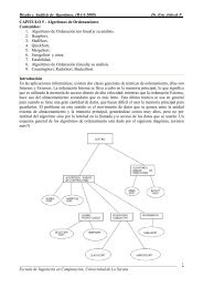
systems (Jha et al. 2009). What is a comprehensive EHR? An expert consensus<br />
view of the functionality required suggested 24 core functions (see Fig. 1.1) in<br />
four main groups:<br />
•<br />
•<br />
Comprehensive EHR<br />
Clinical documentation<br />
Test and imaging results<br />
Clinical documentation<br />
Decision support<br />
Order entry (requests)<br />
Test and imaging results<br />
Fig. 1.1 Functionality of a comprehensive EHR system<br />
Patient demographics<br />
Doctors notes<br />
Nursing assessments<br />
Problem lists<br />
Medication lists<br />
Discharge summaries<br />
Advanced directives (living wills)<br />
Clinical guidelines<br />
Clinical reminders<br />
Drug-allergy alerts<br />
Drug-drug interaction alerts<br />
Drug-laboratory interaction alerts<br />
Drug-dose support<br />
Radiology tests<br />
Laboratory tests<br />
Prescribing<br />
Consultant requests<br />
Nursing orders<br />
Clinical laboratory reports<br />
Radiology reports<br />
Radiology images<br />
Diagnostic test results<br />
Diagnostic test images<br />
Consultant reports
1 The <strong>Health</strong> Information Revolution<br />
• Decision support<br />
• Computerized provider-order entry<br />
In ambulatory care (doctors’ offices), the proportion of doctors using comprehensive<br />
and basic EHR systems are 4% and 9%, respectively (DesRoches et al. 2008).<br />
The problem is not one of technology. In the United Kingdom, all GPs (yes,<br />
100%) use EHRs in their consulting rooms and a large proportion work paper-free<br />
– they rely entirely on electronic records while consulting. However, GP surgeries,<br />
in which all records are electronic, are not able to share data with hospitals, primarily<br />
because the hospitals do not use computers for maintaining patient records. In<br />
2009, most hospital doctors do not use computers for maintaining case notes in the<br />
consulting room or at the bedside.<br />
There are several reasons why GPs use computers but hospital doctors do not<br />
(Benson 2002). Incentives have played a big part. Over a 40-year period, the leaders<br />
of the GP profession worked with the government to provide incentives and to<br />
remove barriers to computerizing practices. By 1996, 96% of British GPs were<br />
already using computers.<br />
The story of the computer-printed prescription form used in England FP10<br />
(comp) provides a good example of the way that governments can remove barriers<br />
to computerization. The computer form is twice the width of a standard prescription,<br />
with a large blank area on the right-hand side. The original reason for the<br />
blank space was that narrow tractor-feed printers were not available when the form<br />
was developed (for use in one practice only) in the mid-1970s. The blank righthand<br />
side was later used to provide each patient with a record of his or her medication;<br />
this is so useful that no one has seriously considered doing away with it. In<br />
1981, the Department of <strong>Health</strong> approved the national use of the form, in spite of<br />
well-founded reservations that the wider form would be more expensive and computers<br />
would make it easier to prescribe more, hence increasing costs. This simple<br />
regulatory change was critical in enabling the development and spread of GP computing,<br />
where computer-assisted repeat prescribing saves time and improves legibility<br />
and safety. In most other countries computer-printed prescriptions remained<br />
illegal for many more years, slowing their uptake of computing.<br />
On the other hand, hospital computing has been treated as an administration<br />
overhead (a cost to be contained), and doctors have not been offered incentives<br />
or other encouragement to become involved. At a time when almost 100% of<br />
prescriptions written by GPs are computerized, the proportion of computerized<br />
hospital prescriptions is tiny (probably less than 2% but likely to increase<br />
rapidly).<br />
One issue has been resistance by hospital doctors and managers. This is not new.<br />
Based on his experience in implementing comprehensive EHR systems during the<br />
early 1970s, Melville Hodge wrote:<br />
Success has repeatedly been demonstrated to be the consequence of each doctor, one at a<br />
time, coming to see how his performance is enhanced by investing his always scarce time<br />
in learning how to use the system efficiently. Similarly hospital managers must participate in<br />
and buy into a carefully designed benefits realization program before they can be reasonably<br />
expected to act. (Hodge 1990)<br />
5
6 1 The <strong>Health</strong> Information Revolution<br />
There are other difficulties also. What works well in GP surgeries does not scale to<br />
work in acute hospitals. Attempts to replicate the success of GP computing in<br />
hospitals have failed repeatedly. You cannot shoehorn a system that works well for<br />
one specialty into another.<br />
GPs work as individuals working mainly in a single consulting room, but hospital<br />
clinicians work as teams and are highly mobile; their work is more diverse and<br />
specialized than that of general practice. Hospitals need excellent communication<br />
within the work-group, between doctors, nurses, and other professions. For example,<br />
about 70% of the tasks performed by junior hospital doctors are done together with<br />
another member of staff, usually another doctor (Westbrook et al. 2008).<br />
The information systems used by each specialty need to work together, which<br />
requires the deployment of stringent interoperability standards for each use case.<br />
Many of the standards required have not been agreed; many of those that have been<br />
agreed have not yet been deployed.<br />
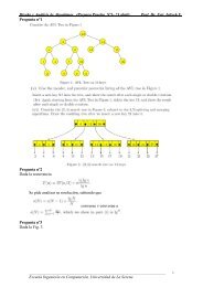
The NHS <strong>Informatics</strong> Review, 2008, 3 sets out a vision to support patient-centered<br />
care in a way that empowers patients to be more involved in their care and<br />
staff to improve NHS performance (Fig. 1.2).<br />
To help achieve buy-in from hospital doctors the review identified five key features,<br />
which are referred to in the report as the “Clinical 5”:<br />
• Patient Administration System (PAS) with integration with other systems and<br />
sophisticated reporting<br />
• Order Communications and Diagnostics Reporting (including all pathology and<br />
radiology tests and tests ordered in primary care)<br />
• Letters with coding (discharge summaries, clinic, and Accident and Emergency<br />
letters)<br />
• Scheduling (for beds, tests, theaters, etc.)<br />
• e-Prescribing including “To Take Out” (TTO) medicines<br />
The review also identified that a major program of standards development would<br />
be needed to enable these goals to be achieved.<br />
1.1 <strong>Health</strong> Care is Communication<br />
<strong>Health</strong> care is a communications industry. Most healthcare processes involve<br />
exchanging information; billions of documents are generated. Consider four<br />
different types of communication, based on the physical distance that the information<br />
has to travel:<br />
•<br />
•<br />
Within the work-group, to record and manage the care of individual patients<br />
Between specialized diagnostic and treatment departments, to request services<br />
and to report results<br />
3 <strong>Health</strong> <strong>Informatics</strong> Review. DH July 2008, Ref 10104
1.1 <strong>Health</strong> Care is Communication<br />
NHS <strong>Informatics</strong><br />
Review 2008<br />
Support high quality care<br />
Clinical 5 priorities<br />
Fig. 1.2 NHS <strong>Informatics</strong> Review<br />
Deliver better safer care<br />
Empower patients<br />
service users, carers<br />
and the public<br />
Empower staff to improve<br />
NHS performance<br />
Patient Administration System (PAS)<br />
with integration with other systems<br />
and sophisticated reporting<br />
Order Communications and<br />
Diagnostics Reporting (including<br />
all pathology and radiology tests<br />
and tests ordered in primary care)<br />
Letters with coding (discharge summaries,<br />
clinic and Accident and Emergency letters)<br />
Scheduling (for beds, tests, theatres etc)<br />
Based around the person<br />
Support clinical<br />
and care processes<br />
Patient access to and<br />
contribute to own records<br />
Public access to<br />
health knowledge<br />
Public access to<br />
service information<br />
Assess quality and<br />
effectiveness<br />
Regulatory activities<br />
Research, planning<br />
and management<br />
e-Prescribing including ‘To Take Out’ (TTO) medicines<br />
• Across organization boundaries between hospital doctors GPs and community<br />
staff, to ensure continuity of care<br />
• From the care provider to payers and regulatory agencies, for revenue and<br />
accountability<br />
These four categories of communication are listed in decreasing order of information<br />
volume yet in increasing order of use of information technology. It is like a<br />
banana republic that invests in airports and motorways, but does nothing to improve<br />
transport for the millions in the cities.<br />
Historically, healthcare information systems have been organized hierarchically,<br />
with the government or payer at the top, then provider organizations such<br />
as hospitals, followed by departments, clinicians, and ultimately the patient (GP<br />
computing in the UK is a notable exception to this model). This hierarchy reflects<br />
the flow of money, authority, and power, but has little in common with the natural<br />
flow of healthcare information needed to care for individual patients; patient care<br />
has more in common with a social network, with each individual patient at the<br />
centre of their own net.<br />
7<br />
Sharing across<br />
organisational boundaries
8 1 The <strong>Health</strong> Information Revolution<br />
1.2 Patient-Centric <strong>Health</strong> Care<br />
The patient is the sole reason for healthcare activity, and so we should focus on<br />
meeting the patient’s needs. Each patient wants to live longer, feel well, and be able<br />
to do what he or she wants. <strong>Health</strong> care is changing from a paternalistic model to<br />
one of partnership between patients and healthcare professionals.<br />
In 2001, the Institute of Medicine’s Crossing the Quality Chasm set out a<br />
manifesto for transforming healthcare systems to become safe, effective, patientcentered,<br />
timely, efficient, and equitable. It called for urgent action to automate all<br />
clinical, financial, and administrative information, and to share that information<br />
electronically among clinicians, patients, and appropriate others within a secure<br />
environment (Institute of Medicine 2001).<br />
In the traditional healthcare model, care was based around discrete visits<br />
and episodes of care; professional autonomy led to variability as each care<br />
professional decided on investigations and treatment based on their own<br />
training and experience. Safety was an individual responsibility; the patient record<br />
was primarily a record of what had happened and was kept secret. The system as a<br />
whole defended professional demarcation, focused on cutting costs, reacted to<br />
patient needs as and when they arose. This model is disappearing fast, but we<br />
still rely on information systems that were originally conceived and designed for<br />
that environment.<br />
The new patient-centric model is quite different: care is based on continuous<br />
healing relationships, customized according to individual patient needs<br />
and values, with the patient as the ultimate source of control. Knowledge is<br />
shared, information flows freely, and decision-making is evidence-based.<br />
Transparency and collaboration are virtues, patient needs are anticipated, and<br />
effort is devoted toward reducing waste (that is, any activity that delivers no benefit<br />
to the patient) (Fig. 1.3).<br />
This change toward partnership and patient-centered care involves changes in<br />
information systems architecture, more along the lines of social networking than<br />
the traditional enterprise-centric systems that have been implemented over the last<br />
30 years or so. A prerequisite of personal health records (PHR) systems is data<br />
liquidity using open standards. Unfortunately, most existing EHR systems have<br />
incompatible means of acquiring, processing, storing, and communicating data<br />
(Mandl et al. 2001).<br />
Most patients, doctors and other healthcare professionals find it surprising<br />
that when so much of what we do is performed over the Internet, we are still<br />
not able to share information seamlessly to provide joined-up patient-centric<br />
care. Coiera has pointed out that health systems are socio-technical systems,<br />
involving the interaction of people and technology and that we cannot design<br />
organizational and technical systems independently of each other, nor expect to<br />
reinvent healthcare systems successfully without a thorough understanding of<br />
the technology needed to make all the parts interoperate smoothly (Coiera<br />
2004).
1.3 Stages of Information Handling<br />
<strong>Health</strong>care is changing<br />
Focus of care<br />
Variation mainly due to<br />
Control<br />
Decision-making<br />
Safety<br />
Openness<br />
Reactivity<br />
Economics<br />
Collaboration<br />
Information Technology<br />
1.3 Stages of Information Handling<br />
from: Discrete visits/episodes<br />
to: Ongoing care relationship<br />
from: Professionals in control<br />
to: Patient in control<br />
to: A system property<br />
from: Secrecy<br />
from: Training and experience<br />
to: Evidence-based<br />
from: Individual responsibility<br />
to: Transparency (subject to privacy)<br />
from: React to patient needs<br />
to: Anticipate patient needs<br />
from: Cut costs<br />
to: Eliminate waste<br />
from: Demarcation<br />
to: Cooperation<br />
from: Professional autonomy<br />
to: Patient needs and values<br />
from: Silos<br />
Fig. 1.3 Differences between traditional and patient-centric health care<br />
to: Information sharing<br />
Let us go back to basics. Information handling has evolved over several thousand<br />
years through four distinct stages as originally set out by Marshall McLuhan in<br />
Gutenberg’s Galaxy (McLuhan 1962).<br />
In the first stage, information and knowledge was held only in the human brain<br />
and transferred from one person to another by speech. Oral tribal culture provides<br />
an example. Access depends on the presence of the person with the knowledge,<br />
which is lost forever when a person dies. A good deal of one-to-one health care still<br />
relies on the human memory and speech.<br />
The second stage began with the invention of handwriting. Handwritten records<br />
are formatted at the time of writing, cannot be replicated without transcription, and<br />
often illegible. Modern health care, involving teams of doctors and nurses, each<br />
doing a specialized task, would be impossible without written records.<br />
9
10 1 The <strong>Health</strong> Information Revolution<br />
The third stage was triggered by the invention of printing by Johannes Gutenberg<br />
around 1455, which provided the means to replicate and broadcast information<br />
widely. This led to the Renaissance, the Age of Enlightenment, the Industrial<br />
Revolution and the Information Society. The impact of this top-down broadcasting<br />
and dissemination of knowledge on medical education has been massive, but there<br />
has been little impact on how people perform routine health care and maintain care<br />
records.<br />
The fourth and last stage, the electronic age, has its origins in the development<br />
of electronic computers and information science during World War II and has been<br />
gathering pace exponentially ever since, driven by the Laws of Moore and Metcalfe,<br />
leading to the explosive development of the Internet, the Web, mobile phones, and<br />
social networking.<br />
Moore’s Law is the prediction made in 1965 that the power of computer devices<br />
would continue to double every 2 years; this has held good for almost 60 years and<br />
shows few signs of stopping yet.<br />
Metcalfe’s Law is based on the twin observations that the cost of adding each<br />
user to a network is linear but the value each user obtains from that network depends<br />
on the number of users they can link to. Thus, as networks grow, the value to each user<br />
continues to increase and the total value of the network increases exponentially.<br />
It is surprising that health care, the largest and quintessential informationbased<br />
industry, has failed to harness these forces and become joined-up for so long.<br />
The oral tradition and handwritten manuscripts remain prevalent throughout most<br />
of the sector (Fig. 1.4).<br />
<strong>Health</strong> professionals are overwhelmed by information. Herbert Simon noted:<br />
Information consumes the attention of its recipients; a wealth of information creates a<br />
poverty of attention and a need to allocate that attention amongst the overabundance of<br />
information sources that might consume it. (Simon 1971)<br />
The value of information lies in its use, which falls into two main categories:<br />
clinician support at the point of care, and service management.<br />
Clinician support includes all of the tasks needed to support clinical decisionmaking,<br />
to order tests and treatment, to correspond with patients, hospital specialists,<br />
GPs, community and social care services, and to review clinical performance.<br />
The nature of clinical care is ultimately determined by the natural history of<br />
disease processes, which are highly complex but do not change. Clinical care is<br />
task-oriented. At any moment a clinician is performing one of a number of welldefined<br />
tasks, which differ considerably from specialty to specialty, with some<br />
overlap. Clinical care comprises thousands of discrete tasks, each of which has its<br />
own information and communication needs and requires systems, terms, and classifications<br />
tailored to the needs of the task.<br />
Service Management is focused on meeting the contractual obligations of<br />
commissioners and regulators, which, unlike clinical processes, are subject to<br />
frequent and regular change. Managers do not need to understand every detail of<br />
clinical care. They focus on providing a safe, courteous, and efficient service, by<br />
enabling the smooth administration of each patient’s stay or visit, monitoring the<br />
quality of care provided in terms of safety, patient experience, and effectiveness,
1.3 Stages of Information Handling<br />
<strong>Health</strong>care Communication<br />
Communication mode<br />
Type of communication<br />
Uses of Information<br />
Within workgroup<br />
Between specialist units<br />
Between providers<br />
Provider to payer<br />
Care records<br />
Vital signs<br />
Medication chart<br />
Nursing notes<br />
Orders<br />
Reports<br />
Referrals<br />
Prescriptions<br />
Discharge summaries<br />
costs and opportunities to improve efficiency. Management information is invariably<br />
classified into a relatively small number of discrete groups.<br />
Clinical decisions, such as ordering tests, therapy, referrals, and care, determine<br />
the cost and outcome of care. Only a small proportion of cost variance in<br />
health care can be attributed to service efficiency (doing things right). Most<br />
cost and outcome variance is the result of differences in clinical management,<br />
individual doctors’ patterns of treatment and investigation (doing the right things).<br />
It is always important to do tests efficiently, but if the test is inappropriate (e.g., it<br />
is repeated without good reason), it is a waste of resources irrespective of how<br />
efficiently it is performed.<br />
Donald Berwick has written:<br />
The ultimate measure by which to judge the quality of a medical effort is whether it<br />
helps patients (and their families) as they see it. Anything done in health care that does<br />
not help a patient or family is, by definition, waste, whether or not the professions and their<br />
associations traditionally hallow it. (Berwick 1997)<br />
Paper-based patient records are widely recognized as not fit for purpose. For<br />
example:<br />
The medical record is an abomination … it is a disgrace to the profession that created<br />
it. More often than not the chart is thick, tattered, disorganised and illegible; progress<br />
notes, consultants notes, radiology reports and nurses notes are all co-mingled in accession<br />
Oral<br />
Hand-written<br />
Print and broadcast<br />
Direct care<br />
Outcomes<br />
Service management<br />
Fig. 1.4 Aspects of healthcare information and communication<br />
Electronic network and Internet<br />
Cost-control<br />
11<br />
Payment and accountability<br />
Effectiveness<br />
Safety<br />
Efficiency<br />
Delays<br />
Financial control<br />
Regulation<br />
Efficiency<br />
Duplication<br />
Moore's Law<br />
Metcalfe's Law
12 1 The <strong>Health</strong> Information Revolution<br />
sequence. The charts confuse rather than enlighten; they provide a forbidding challenge<br />
to anyone who tries to understand what is happening to the patient. (Bleich and<br />
Lawrence 1993)<br />
A paper record can be used only in one place by one person at a time and is<br />
often not where it is needed. Once to hand, it is hard to find what you want in a<br />
disorganized, illegible, inconsistent, incomplete, badly sorted bundle of paper.<br />
The user has to do all of the work to glean any useful information.<br />
The electronic patient record is key to improved clinical decision-making and<br />
accountability. Information quality is a paramount concern. Computer-based<br />
patient records are legible and the information can be displayed in many different<br />
ways to suit the task at hand. Several people can work on it at different places at the<br />
same time, saving the delays and effort required to locate, retrieve, and transport<br />
paper. Prompts can improve quality and safety, prevent key data being omitted, and<br />
save time by not needing to record the same data time and again.<br />
1.4 <strong>Health</strong> Care Is Complex<br />
<strong>Health</strong> care is inherently fractal. The more closely you look, the more complexity<br />
you find. The information in hospital medical records is enormously varied; it<br />
includes: referral and discharge letters from different doctors; investigation findings<br />
from laboratories and diagnostic imaging departments, medication charts, nursing<br />
notes, ECG traces, plus the history, examination, progress notes, and plans kept by<br />
each doctor.<br />
It is easy to overlook just how flexible paper-based patient records are, in spite<br />
of their deficiencies.<br />
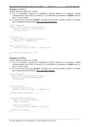
<strong>Health</strong>care communication and information flow patterns involve many people<br />
over a wide geographical area and diverse subject matter. For example, over 30,000<br />
GPs in England refer over 15 million patients a year to 60,000 hospital and<br />
community doctors and receive more than 40 million clinic and discharge letters<br />
in return. Each primary care doctor can refer patients to any specialist and each<br />
specialist can receive referrals from any GP (Fig. 1.5).<br />
Each doctor also communicates with a multitude of specialized investigation and<br />
treatment services, community care agencies, administrative and funding bodies.<br />
This complex many-to-many communication pattern is prevalent throughout the<br />
health and social care services.<br />
The workflow is varied, depending on what is the matter with the patient and at<br />
what stage they are in the process; it changes from one patient to another and from<br />
one care setting to another. The half-life of information (how long a piece of information<br />
has any value) differs enormously in different contexts, such as in outpatient<br />
clinics, on the wards, in intensive care, and during an operation in an operating<br />
theatre.<br />
Each class of clinician has its own needs. The Department of <strong>Health</strong> recognizes<br />
more than 60 clinical specialties for doctors plus a similar number of other nursing,
1.5 Looking Back<br />
Fig. 1.5 Information flows<br />
therapy and investigation specializations. Each specialty has its own governance,<br />
education, and quality assurance requirements, speaks its own dialect and has its<br />
own ways of working. Clinical heterogeneity helps explain why many successful<br />
electronic patient record systems are limited to single specialties, such as general<br />
practice, maternity care, or renal dialysis, where the needs are relatively homogeneous<br />
and well-understood.<br />
The situation is exacerbated because most healthcare professionals are mobile<br />
and can be found on any ward where they have patients, in clinics, at any one of<br />
several hospitals, on domiciliary visits in the community, in laboratories, or in their<br />
own office.<br />
The concept of the one-size-fits-all patient record has not been very successful<br />
except where great efforts have been made to tailor the system to individual needs<br />
and management has been able to mandate its use, such as in the Veterans<br />
Administration hospitals, where clinicians were offered no choice as to whether or<br />
not to adopt it.<br />
1.5 Looking Back<br />
Sometimes it pays to stand back and take the long view. We now have almost 40<br />
years experience in implementing EHRs and know what works and what does not.<br />
There is no excuse for not learning the well-documented lessons of history<br />
13
14 1 The <strong>Health</strong> Information Revolution<br />
1.5.1 Problem-Oriented Medical Records<br />
The Problem-Oriented Medical Record (POMR), first described by Larry Weed in<br />
1968 (Weed 1968), was one of the first and most influential attempts to improve the<br />
structure of the patient record.<br />
Weed’s POMR divides the record into two parts. The first, called the database<br />
covers the patient’s social, family, and past medical history. The second main section<br />
is the progress notes. Progress notes are organized under problems.<br />
A problem is anything that causes concern, not only a diagnosis. The problem<br />
list is a list of all the patient’s problems indicating those that are active and those<br />
that have been resolved.<br />
Each progress note has a problem heading and four subheadings, using the<br />
acronym SOAP:<br />
S – Subjective, meaning the information provided about history and symptoms by<br />
the patient or relative.<br />
O – Objective, meaning information obtained by direct examination of the patient<br />
or from clinical investigations (laboratory, radiology, etc.).<br />
A – Assessment, meaning the clinicians assessment about what is the matter with<br />
the patient (diagnosis), prognosis, etc.<br />
P – Plan, meaning the future plan of action, including investigations and treatment<br />
(drug prescriptions, physiotherapy, surgery, and so on). Drugs prescribed are<br />
also listed in a separate medication list. This section is a problem-specific<br />
care plan.<br />
From 1967 to 1982 Larry Weed was funded by the US government to implement<br />
a remarkable problem-oriented electronic patient record system known as PROMIS,<br />
based on the use of touch-screen terminals. This pioneering project was implemented<br />
for many years on medical and gynecological wards at the University of<br />
Vermont, but it was withdrawn after federal funding ceased (Schultz 1988). Weed<br />
went on to develop problem-knowledge couplers (PKC), which match detailed<br />
patient information with an extensive medical database to provide guidance tailored<br />
to individuals (Weed 1991).<br />
The POMR concept was taken up in primary care in the United Kingdom where<br />
most GP systems are problem-oriented, linking medication and tests with problems<br />
(Fig. 1.6). 4<br />
4 The first widely used problem-oriented GP system in the was Abies System 5, introduced in<br />
1987, distributed by AAH Meditel, and one of the ancestors of iSOFT’s Lorenzo system.
1.5 Looking Back<br />
Problem-Oriented<br />
Medical Record (POMR)<br />
Database<br />
Problem List<br />
Progress Notes<br />
Fig. 1.6 Problem-Oriented Medical Records (POMR)<br />
1.5.2 El Camino Hospital Project<br />
Past Medical History<br />
Social history<br />
Family History<br />
Administration<br />
Active problems<br />
Inactive problems<br />
Subjective<br />
Objective<br />
Assessment<br />
Treatment<br />
Follow-up<br />
Referral<br />
Medication<br />
Therapy<br />
The first hospital to implement a comprehensive EHR was the El Camino hospital<br />
in California, which went live in 1971. This was subjected to a detailed 6-year<br />
evaluation that compared its costs and other outcomes with those of control hospitals.<br />
Such detailed long-term evaluations are rare, but other studies have shown<br />
similar findings. Introducing electronic health records into a large hospital i difficult<br />
and time-consuming, but the scale of efficiency improvements can be<br />
large.<br />
The following quotes come from an account of the experience by Melville<br />
Hodge, who led the project for the supplier (Hodge 1990).<br />
The project met:<br />
Plan<br />
Registration<br />
Demographics<br />
History<br />
Allergies<br />
Vaccinations<br />
Screening<br />
Operations<br />
Symptoms<br />
Clinical findings<br />
Test results<br />
Diagnosis<br />
massive resistance from important segments of the medical staff, spreading quickly to ...<br />
national newspaper headlines. This resistance, initially justified in part by early system<br />
shortcomings, seemed intractable.<br />
15
16 1 The <strong>Health</strong> Information Revolution<br />
Hodge warns:<br />
Never forget that introduction of [EHR] into a hospital impacts a human organization to<br />
perhaps an unparalleled degree. If the need to manage the change process is ignored,<br />
resistance and even rebellion may be reasonably predicted.<br />
The resistance was overcome:<br />
by effective leadership of the more visionary El Camino physicians.<br />
The outcome was that 10 years later, the hospital chief executive could claim:<br />
[T]he hospital inpatient cost per case is 40% less than the county average for 13 similar<br />
community hospitals.<br />
1.5.3 The NHS National Programme for IT<br />
The English National <strong>Health</strong> Service National Programme for IT (NPfIT)<br />
demonstrates the need for appropriate standards to be fully deployed (Brennan 2005).<br />
The central recommendation of the Wanless Report, which led to the creation of the<br />
program was for:<br />
a doubling of spending on ICT to fund ambitious targets of the kind set out in the NHS<br />
Information Strategy. To avoid duplication of effort and resources and to ensure that the<br />
benefits of ICT integration across health and social services are achieved, the Review<br />
recommends that stringent standards are set from the centre to ensure that systems across<br />
the UK are fully compatible with each other. (Wanless 2002)<br />
More detail was provided in a Strategy document 3 months later, which stated:<br />
The core of our strategy is to take greater control over the specification, procurement,<br />
resource management, performance management and delivery of the information and IT<br />
agenda. We will improve the leadership and direction given to IT, and combine it with<br />
national and local implementation that are based on ruthless standardisation. (DH 2002)<br />
The vision of integration across health and social services and cross-UK<br />
compatibility had been quietly dropped. The focus was to provide a centrally procured<br />
set of one-size-fits-all systems. However, the NHS is not a monolithic organization,<br />
but may be better thought of as comprising thousands of units linked by a single<br />
payer. It is more like an industry sector than a single service. Linking such an ecosystem<br />
requires integration standards to be deployed everywhere.<br />
The Strategy listed ten key elements of the national program, the final one<br />
being to:<br />
create national standards for data quality and data interchange between systems at local,<br />
regional and national levels. (op cit paragraph 2.3.2)<br />
At the outset, the National program underestimated the requirement to develop<br />
and deploy the standards needed to enable interoperability at all levels and<br />
focused attention on providing only those needed to support links to national<br />
services.
1.5 Looking Back<br />
The Strategy even implied that the relevant standards were already available.<br />
Work is already underway on a strategy for electronic Clinical Communications and a<br />
report is due at the end of March 2002 (sic). This will guide the implementation of the<br />
electronic pathology results to GPs and GP to GP record transfer (both due in December<br />
2002); radiology reporting and electronic discharge summary implementation due to<br />
commence in March 2003; and the standards for the electronic transfer of prescriptions will<br />
be available later this year. (op cit paragraph 4.2.2)<br />
The first phase of the project, between April 2002 and March 2003, was to be<br />
used to:<br />
define the data and data interchange standards we will require in the future. (op cit<br />
paragraph 1.2.3)<br />
These targets were missed. One of the reasons was that at that time the<br />
responsibility for standards development was spread across several independent<br />
organizations with responsibility for strategic direction, defining standards, ratifying<br />
standards and certification testing. No one was in control of the whole picture.<br />
These national functions were eventually brought together under NHS Connecting<br />
for <strong>Health</strong>, but this took until April 2005 and by then many key decisions on scope,<br />
technology, and budgets had been set.<br />
A major effort was directed toward the development of data interface specifications<br />
for national services using HL7 Version 3, but the specification and deployment of<br />
local and regional services was left to the Local Service Providers who adopted<br />
different releases of Hl7 Version 2.<br />
In Canada, the <strong>Health</strong> Infoway project has learnt some of these lessons and in<br />
2006 established a centrally funded Infoway Standards Collaborative, to:<br />
support and sustain health information standards and foster collaboration to accelerate the<br />
implementation of pan-Canadian standards-based solutions. 5<br />
In the United States, the HITECH Act has established a statutory <strong>Health</strong> Information<br />
Standards Committee as well as a budget of $2 billion to support the Office of the<br />
National Coordinator for <strong>Health</strong> Information Technology (ONCHIT) to build the<br />
requisite infrastructure; develop health information exchange capabilities at the<br />
regional and state levels; and provide grants to assist with implementation, education<br />
adoption, and interoperability.<br />
1.5.4 Lessons from Denmark<br />
The development and deployment of healthcare interoperability standards are hard,<br />
but important lessons can be learnt from experience in Denmark, which has been<br />
uniquely successful in linking primary care doctors with laboratories, hospitals,<br />
and pharmacies.<br />
5 http://www.infoway-inforoute.ca/lang-en/standards-collaborative<br />
17
18 1 The <strong>Health</strong> Information Revolution<br />
In 1994 the Danish Government established MedCom as a national public project<br />
collaborating with public authorities, healthcare organizations, and private firms.<br />
Initially, a small group of experts developed a set standards for referrals, discharge<br />
letters, laboratory and radiology requests and reports, prescriptions, and reimbursement<br />
claims, which were based on European standards developed by CEN TC251.<br />
Between 1994 and 1996 these specifications were piloted in 11 independent locally<br />
managed projects, revised and retested in a further 15 projects. The experience gained<br />
was brought together in voluminous documentation:<br />
in such detail and so accurately and precisely that the overwhelming opinion is that<br />
MedCom’s standards can indeed be used from Gedser to Skagen (from one end of Denmark<br />
to the other). (MedCom 1996)<br />
Unfortunately, the early optimism (hubris) was not justified. The information sent was<br />
not always displayed or was misinterpreted due to ambiguity in data definitions of data<br />
elements, local coding schemes, and lack clarity about which elements were mandatory<br />
or optional. These issues were tackled in a 3-year consolidation project leading to revised<br />
standards and compulsory certification. By the end of 2002, 53 software versions had<br />
been certified and the error rate reduced by more than 70% (Johansen et al. 2003).<br />
By 2008, all Danish GPs receive discharge summaries and lab results electronically;<br />
most prescriptions and referrals are also sent electronically. One of the key<br />
lessons is that success has taken time to achieve (Fig. 1.7) (MedCom 2008).<br />
Three factors contributed to the Danish success.<br />
Fig. 1.7 Rise in interoperability in Denmark over the 16-year period 1992–2008. Source: Medcom
1.6 Evidence-Based Medicine<br />
Steady political support was provided over many years, even when things went<br />
badly. Central support kept the stakeholders together and enabled modest direct<br />
financial incentives for participants. As in the United Kingdom, the use of computers<br />
by GPs is voluntary, but appropriate incentives produced high participation.<br />
Second, the project was established as a formal collaboration between government,<br />
industry, and healthcare providers. Funding is provided one-third each by the state,<br />
the County Association, and other sources including doctor’s organizations and<br />
industry (Protti and Johansen 2003).<br />
Third, the project was proactive and innovative in training suppliers to understand<br />
the specifications in precisely the same way. For several years, usually in<br />
winter when the weather is bad in Denmark, a few programmers from each software<br />
supplier were invited to a special workshop on the Mediterranean coast.<br />
These workshops achieve high levels of attendance, collaboration, and bonding.<br />
1.6 Evidence-Based Medicine<br />
Evidence-based medicine (EBM) is one of the most important developments in the<br />
clinical use of information over the last 20 years, representing a sea change in the<br />
way that clinicians are taught to think. EBM addresses the challenge of finding a way<br />
to ensure that clinicians base their day-to-day decision-making on current best evidence.<br />
All too often clinicians are unaware of the available evidence or fail to apply<br />
it. Even those who are aware of the evidence risk making the wrong recommendations<br />
if they do not involve patients in the decision-making process (Guyatt et al. 2004).<br />
EBM is the conscientious, explicit, and judicious use of current best evidence in<br />
making decisions about the care of individual patients. The practice of evidencebased<br />
medicine requires the integration of individual clinical expertise with the best<br />
available external clinical evidence from systematic research and our patient’s<br />
unique values and circumstances (Straus et al. 2005).<br />
The practice of EBM has five steps:<br />
1. Convert our need for information (about prevention, diagnosis, prognosis, therapy,<br />
causation, etc.) into an answerable question<br />
2. Track down the best evidence to answer the question<br />
3. Critically appraise the evidence for validity and applicability<br />
4. Integrate the critical appraisal with our clinical expertise and our patient’s unique<br />
biology, values, and circumstances<br />
5. Evaluate our performance<br />
The first step is to identify the answerable questions. 6 There are two main types of<br />
questions – background and foreground.<br />
Background questions occur when we have limited knowledge of the subject.<br />
These usually begin with a question root (who, what, where, when, how, why),<br />
followed by a verb and a disorder, e.g., “what causes Lyme disease?” 6<br />
6 Lyme disease is an infectious disease transmitted by ticks.<br />
19
20 1 The <strong>Health</strong> Information Revolution<br />
Foreground questions ask for specific knowledge about managing patients with<br />
a disorder and are usually specific to a patient’s problem, intervention (treatment,<br />
test, exposure, perception, etc.), comparison interventions (if relevant) and clinical<br />
outcomes of interest.<br />
These questions can be grouped into ten central issues in clinical work:<br />
• Clinical findings – history and physical examination<br />
• Aetiology – causes of disease including iatrogenic forms<br />
• Clinical manifestations – how often and when a disease causes clinical<br />
manifestations<br />
• Differential diagnosis – possible causes (likely, serious, and responsive to<br />
treatment)<br />
• Diagnostic tests – selection and interpretation of tests to confirm or exclude a<br />
diagnosis<br />
• Prognosis – likely clinical course and possible complications<br />
• Therapy – appropriate treatments<br />
• Prevention – risk factors and screening<br />
• Patient experience and meaning – empathy with the patient’s situation<br />
• Self-improvement<br />
This classification of types of clinical question could be used to classify<br />
access to answers in electronic knowledge tools, using appropriate icons or<br />
color codes.<br />
Detailed advice of a general in guidance needs to be tested for issues that make<br />
the instructions locally impractical, such as<br />
•<br />
•<br />
•<br />
•<br />
Burden – is the frequency too low to warrant action?<br />
Beliefs – do the risks outweigh the benefits?<br />
Bargain – are there better uses of our resources?<br />
Barriers – are there insurmountable barriers (geographic, organizational,<br />
traditional, etc.) to adoption?<br />
These are referred to as the “killer Bs.”<br />
In her survey of implementing evidence-based findings, Greenhalgh notes that<br />
“standard issue” guidelines and protocols and didactic education are usually ineffective,<br />
while high-quality, computerized decision support and interactive handson<br />
education are much more effective (Fig. 1.8) (Greenhalgh 2001).<br />
1.7 EHR System Functional Model<br />
In this field, as in many others, one of the difficulties is definition of terms. What<br />
do we mean by the terms such as e-prescribing or clinical decision support?<br />
We need an agreed set of definitions so that users, regulators, purchasers, and<br />
suppliers can be sure that they are all talking about the same thing.
1.7 EHR System Functional Model<br />
Fig. 1.8 Evidence-based medicine<br />
The need for shared understanding of meaning is the core problem of health<br />
interoperability and is the central theme running through the whole of this book.<br />
A comprehensive hierarchical breakdown of the capabilities of EHR systems has<br />
been developed by HL7 as the EHR System Functional Model (EHR-S FM). At the<br />
top level, there are three groups of functions 7 :<br />
•<br />
•<br />
•<br />
Direct care: functions used for providing direct health care, or self-care, to one<br />
or more persons<br />
Supportive: functions that use EHR data to support the management of healthcare<br />
services and organizations<br />
Information Infrastructure: backbone elements of security, privacy, registry,<br />
interoperability, and terminology<br />
7 HL7 EHR System Functional Model: A Major Development Towards Consensus on Electronic<br />
<strong>Health</strong> Record System Functionality. A White Paper, 2004<br />
21
22 1 The <strong>Health</strong> Information Revolution<br />
Fig. 1.9 Direct care functions
1.7 EHR System Functional Model<br />
The whole HL7 EHR System Functional Model taxonomy is shown as an Annexe<br />
to this chapter; it provides an overview of the scope of health informatics in general<br />
and EHRs in particular. It provides a reference list of over 160 functions that may<br />
be present in an Electronic <strong>Health</strong> Record System (EHR-S).<br />
The function list is described from a user perspective with the intent to enable<br />
consistent expression of system functionality. This EHR-S Functional Model, through<br />
the creation of Functional Profiles, enables a standardized description and common<br />
understanding of functions sought or available in a given setting (e.g., intensive care,<br />
cardiology, office practice in one country or primary care in another country).<br />
The EHR-S FM is not a list of specifications for messaging, implementation, or<br />
conformance. Nor is it a specification for an actual EHR-S. However, the EHR-S<br />
FM is a valuable resource for industry, healthcare providers, governments, and other<br />
organizations to uses as a common language (tool) for discussing the functionality<br />
of electronic health records (Figs. 1.9–1.11).<br />
Supportive Functions:<br />
HL7 EHR System<br />
Functional Model<br />
Clinical support<br />
Measurement, analysis, research and reports<br />
Administrative and financial<br />
Fig. 1.10 Supportive functions<br />
Registry notification<br />
Donor management support<br />
Provider information<br />
Patient directory<br />
Scheduling<br />
Information view<br />
Access levels<br />
<strong>Health</strong>care resource availability<br />
Manage practitioner/patient relationships<br />
Subject to subject relationship<br />
Acuity and severity<br />
Location within facility<br />
On call location<br />
Location or offices<br />
Registry or directory<br />
Demographics<br />
Location with a facility<br />
Residence<br />
Bed assignment<br />
De-identified data request management<br />
Encounter/episode of care management<br />
Information access for supplemental use<br />
Administrative transaction processing<br />
Supportive function maintenance<br />
Measurement, monitoring and analysis<br />
Report generation<br />
Genealogy<br />
Insurance<br />
<strong>Health</strong> record output<br />
Standard report generation<br />
Ad hoc query and report generation<br />
Specialised views<br />
Encounter-specific functionality<br />
Automated generation of admin data<br />
Support remote health care services<br />
Other Support<br />
Rules-driven clinical coding assistance<br />
Financial admin coding<br />
Integrate cost/financial information<br />
Patient enrollment<br />
Eligibility verification<br />
Service authorizations<br />
Service requests and claims<br />
Claims and encounter reports for reimbursement<br />
Related by other means<br />
Update clinical decision support system guidelines<br />
Patient education material<br />
Patient reminder information<br />
Public health related updates<br />
Outcome measures and analysis<br />
Performance and accountability<br />
23<br />
<strong>Health</strong> service report at conclusion of episode of care
Entity authentication<br />
24 1 The <strong>Health</strong> Information Revolution<br />
Entity authorization<br />
Entity access control<br />
Non-repudiation<br />
Security<br />
Secure data exchange<br />
Secure data routing<br />
Information attestation<br />
Patient privacy and confidentiality<br />
Data retention, availability and destruction<br />
Auditable records<br />
Synchronization<br />
<strong>Health</strong> record information and management<br />
Extraction of health record information<br />
Unstructured<br />
Information Infrastructure<br />
HL7 EHR System<br />
Functional Model<br />
Store and manage health record information<br />
Structured<br />
Registry and directory services<br />
Standard terminologies and terminology models<br />
Maintenance and versioning of standard terminologies<br />
Standard terminologies and terminology services<br />
Terminology mapping<br />
Interchange standards<br />
Interchange standards versioning and maintenance<br />
Standards-based interoperability<br />
Standards-based application integration<br />
Interchange agreements<br />
Business rules management<br />
Workflow management<br />
Fig. 1.11 Information infrastructure functions
Chapter 2<br />
Why Interoperability is Hard<br />
2.1 What is Interoperability?<br />
The term interoperability means different things to different people. For example,<br />
the HIMSS Dictionary of <strong>Health</strong>care Information Technology Terms, Acronyms and<br />
Organizations lists 17 definitions, from the strictly technical factor to social, political,<br />
and organizational factors (HIMSS 2006).<br />
A widely used definition is:<br />
Interoperability is ability of two or more systems or components to exchange information<br />
and to use the information that has been exchanged. (Institute of Electrical and Electronics<br />
Engineers 1990)<br />
The HL7 EHR Interoperability Work Group has developed a framework, which<br />
covers three different points of view (Gibbons et al. 2007):<br />
• Technical interoperability<br />
• Semantic interoperability<br />
• Process interoperability<br />
These concepts are interdependent, and all three are needed to deliver significant<br />
business benefits.<br />
Technical interoperability moves data from system A to system B, neutralizing<br />
the effects of distance. It is domain-independent. It does not know or care about the<br />
meaning of what is exchanged. One of the foundations of technical interoperability<br />
is Claude Shannon’s information theory, which proved that it is possible to achieve<br />
100% reliable communication over a noisy channel (Shannon 1948).<br />
Semantic interoperability ensures that system A and system B understand the<br />
data in the same way. It allows computers to understand, interpret, and use data<br />
without ambiguity. This is specific to domain and context and usually involves the<br />
use of codes and identifiers. Semantic interoperability is at the core of what we<br />
usually mean by healthcare interoperability.<br />
Process interoperability coordinates work processes, enabling the business processes<br />
at the organizations that house system A and system B to work together.<br />
Process interoperability is achieved when human beings share a common under-<br />
T. Benson, Principles of <strong>Health</strong> Interoperability HL7 and SNOMED, HI,<br />
DOI 10.1007/978-1-84882-803-2_2, © Springer-Verlag London Limited 2010<br />
25
26 2 Why Interoperability is Hard<br />
standing, so that business systems interoperate and work processes are coordinated.<br />
They obtain benefits only when they use the new system in their day-to-day work;<br />
if it is not used as intended, for whatever reason, it is a failure. The importance of<br />
reengineering work processes to take full advantage of electronic systems has long<br />
been recognized, but the lessons have not been well-learnt.<br />
The more we know about the three types of interoperability, the less likely we<br />
are to underestimate what is required to make health systems interoperable.<br />
2.2 Benefits<br />
The benefits of joined-up health care, to provide the right information at the right<br />
time and place, are predicated on deploying and using standards that enable computer<br />
systems to exchange information in a way that is safe, secure, and reliable.<br />
The problem with standards is not that there are so many to choose from, but that<br />
we have not deployed those we have and that there is no regulator to make deployment<br />
happen. Standards that are not deployed are a waste of time and effort.<br />
The center of the star at the right of the figure below indicates a single specification<br />
being used for linking the six domains (Fig. 2.1). This replaces the 15 separate<br />
specifications shown on the left-hand side.<br />
The benefits increase exponentially and more parties are involved, because the<br />
number of interfaces needed to connect N systems increases using the formula (N²–<br />
N)/2. Without using a standard in this way, linking two nodes needs only a single<br />
interface, which can easily be agreed by people sitting around a table; linking six nodes<br />
requires 15 interfaces; but linking 100 nodes requires 4,950 interfaces (Fig. 2.2).<br />
Examples of functions needing interoperability cover a wide range:<br />
• Requests for investigations such as laboratory tests and radiology<br />
• Prescriptions for medication and other therapy in hospitals and in the community<br />
• Orders for nursing care, equipment, meals, and patient transport<br />
• Investigation reports from laboratories, radiology, and other diagnostic departments<br />
Fig. 2.1 The benefits of one standard
2.2 Benefits<br />
Fig. 2.2 Interoperability standards<br />
• Administrative data such as patient registration and identification, clinic appointments,<br />
admissions, discharges, and transfers (ADT)<br />
• Letters and memos from one clinician to another, including referral, clinic and<br />
discharge letters and opinions exchanged between hospital specialists, GPs, and<br />
community services<br />
• Transfer and merging of electronic medical records between GPs and within and<br />
between hospitals and community services<br />
• Information used for management, audit, and monitoring<br />
• Commissioning, billing, and accountancy data<br />
The numbers of transactions in healthcare systems can be vast. For example, in<br />
2007 a single system (the EHR system) at one large hospital (the Mayo Clinic in<br />
Rochester, MN) processed 660 million HL7 messages or about two million<br />
messages a day. 1<br />
1 Anthony J., Personal Communication.<br />
27
28 2 Why Interoperability is Hard<br />
2.3 Need for a Lingua Franca<br />
Problems begin because each computer system stores data internally in a different<br />
way. This means that to communicate, data has to be translated from one format<br />
or internal language into another. The solution is often achieved by translating<br />
to an intermediate lingua franca (such as a version of HL7) that is understood by<br />
each party.<br />
There are two translations in any interchange; first from the native language of<br />
System A to the lingua franca; second, from the lingua franca to the native language<br />
of System B.<br />
When we talk about a language we mean both the syntax, grammar or information<br />
structure of the language and its semantics, vocabulary, or terminology.<br />
The Rosetta stone from ancient Egypt, now in the British Museum, provides an<br />
analogy. The Rosetta stone contains the same proclamation in three languages, used<br />
by the priests (Hieroglyphic), the court (Greek), and the people (Demotic). In our<br />
context, the three languages could be those used by a sending system, the receiving<br />
system and a common lingua franca used for information interchange, such as HL7.<br />
The meaning of a message is precisely the same in each language but the notation<br />
is quite different.<br />
The inscribers of the Rosetta stone only needed to perform their translation once,<br />
but in computer interoperability, each and every message has to be translated from<br />
one format to another without error. The choice of interchange language is not<br />
sufficient to ensure interoperability. Each transaction needs to be defined in unambiguous<br />
detail as part of a complete, consistent, coherent, and computer-readable<br />
set of specifications for interoperability between the machines to minimize any<br />
possibility of error.<br />
2.4 Electronic <strong>Health</strong> Records<br />
Clinical information is complex, but before exploring the variety let us look at ways<br />
in which clinical information is similar.<br />
In their seminal paper, Rector, Nowlan, and Kay (Rector et al. 1991) describe<br />
how an electronic health record (EHR) is best thought of as a collection of statements,<br />
which is a faithful record of what clinicians have heard, seen, thought, and<br />
done. The EHR is not a collection of facts, but a set of observations about a particular<br />
patient, which have been made by clinicians, each at a specific time and place<br />
for some purpose.<br />
Because each clinical statement is an observation, it is quite possible for two<br />
statements about the same event to disagree with each other, but this can be<br />
resolved if the context or provenance of each statement (who stated it, when, and<br />
where) is recorded. As with a work of art, a statement without provenance is of<br />
doubtful validity.
2.4 Electronic <strong>Health</strong> Records<br />
The ISO 13606 Reference Model for electronic health record communication<br />
sets out a useful hierarchy of clinical information in the context of exchanging<br />
clinical information between parties. 2<br />
• Extract: The top-level container of all or part of the electronic health record<br />
(EHR) of a single subject of care (patient) is known as the EHR Extract.<br />
• Composition: The EHR is made up of Compositions. The Composition is a<br />
key concept; it is the set of information committed to one EHR by a clinician<br />
relating to a specific clinical encounter. Progress notes, laboratory test reports,<br />
discharge summaries, clinical assessments, and referral letters are all examples<br />
of Compositions.<br />
• Folder: Compositions may be grouped together into Folders and sub-Folders.<br />
Folders may be used as containers for various purposes, grouping together<br />
the records by episode, care team, clinical specialty, condition, or time<br />
period.<br />
• Entry: Each Composition comprises a number of Entries, also known as Clinical<br />
Statements. An Entry is the information recorded in the EHR as a result of a<br />
single clinical action, observation, interpretation, or intention. It may be thought<br />
of as a line in the record. Examples include the entries about a symptom, a<br />
laboratory result, a diagnosis, or a prescribed drug.<br />
• Section: Entries may be grouped together in Sections. A Section is a grouping<br />
of related data within a Composition usually under a heading such as Presenting<br />
History, Allergies, Examination, Diagnosis, Medication, and Plans. Sections may<br />
have subsections.<br />
• Element: The leaf node of the EHR hierarchy is an Element, which is a single<br />
data value, such as systolic blood pressure, a drug name, or body weight.<br />
• Cluster: Related Elements may sometimes be grouped into Clusters. For<br />
example, systolic and diastolic blood pressures are separate Elements, but may<br />
be grouped into a Cluster (e.g., 140/90), which represents one Item in an Entry<br />
(Fig. 2.3).<br />
Each clinical specialty has its own way of working. The grand vision of joined-up<br />
health care is predicated on the notion that patient records can be shared electronically<br />
between clinicians from different specialties. Historically, this has been largely<br />
wishful thinking. There have been few successes and many failures. Yet, this is the<br />
promise of President Obama’s HITECH Act and was a specific but largely unrealized<br />
objective of the NHS National Program for IT, which was established in 2002. Every<br />
success has depended on the certified use of agreed standards.<br />
First, we must recognize that it is difficult to share information between different<br />
computer applications even within the same specialty. This is because each computer<br />
application stores data in a different way and may use different internal codes.<br />
The GP2GP project in England illustrates the point. Patients in England have a lifelong<br />
2 ISO 13606-1:2008. <strong>Health</strong> <strong>Informatics</strong> – Electronic health record communication – Part 1: Reference<br />
Model<br />
29
30 2 Why Interoperability is Hard<br />
Fig. 2.3 CEN EN13606 EHR Structure<br />
medical record, which follows them when they move from one GP to another. In an ideal<br />
world, each patient’s records would be sent electronically from their old practice to the<br />
new in a manner that minimizes risk and avoids the need to reenter information.<br />
The GP2GP project set out to do just that, although the project’s leaders recognized<br />
that it could a poisoned chalice. 15 The work has been every bit as difficult as predicted<br />
and each record has to be carefully quality-checked before transmission and on<br />
receipt; but after 7 years work it is a qualified success story, but not the Holy Grail.<br />
Even within the same specialty, the information about an outpatient visit differs<br />
greatly from that about an elective surgical operation or inpatient discharge<br />
summary following an emergency admission.
2.5 Analysis is Paramount<br />
For example, consider the following types of document. At one level each of these<br />
could be regarded as a discharge summary, written from a hospital to a GP, summarizing<br />
the outcome of a visit or episode of care. At another level each is very different.<br />
• An elderly patient discharged home after a fracture<br />
• Mother and baby following birth<br />
• A family after a course of counseling by a psychologist<br />
• Consultation report from an ophthalmologist notifying a proposed operation for<br />
cataract<br />
• Letter to GP notifying that a patient has been diagnosed with cancer<br />
• Discharge from hospital following coronary artery bypass grafts<br />
Postmortem report<br />
Each of these is a composition which relates to a discharge event, but the information<br />
contents are extremely diverse.<br />
Similarly, people sometimes talk about clinical laboratory reports as if they were<br />
homogeneous, but the content of each type of clinical laboratory report is quite different,<br />
as is the work done in each type of laboratory. Histopathology examines cells with<br />
a microscope; microbiology grows bacteria to identify them; haematologists count<br />
blood cells; and clinical chemistry measures chemical concentrations by measuring the<br />
intensity of color changes when chemical are added. The only commonality is that<br />
they all work with specimens extracted from patients. Yet, the specimen workflow is<br />
not fixed; sometimes the requester supplies the sample, sometimes the sample is taken<br />
by the laboratory, and sometimes the patient is required to be present in person.<br />
2.5 Analysis is Paramount<br />
Much of the hard work involved in interoperability lies in teasing out the hundreds<br />
or thousands of different use cases. Information technology analysts, and those who<br />
pay them, tend to focus on the high-volume transactions, which are common across<br />
all specialties and prefer not to deal with the specific needs of the smaller specialties.<br />
Yet, the common stuff is not usually the most important clinically. The value of any<br />
piece of information is, like a piece of art, often related to its rarity.<br />
Even apparently simple concepts such as name and address become complex on<br />
closer inspection and in spite of years of effort, there are still no satisfactory international<br />
standards for name and address. Even the order in which names and<br />
addresses are written varies substantially between countries.<br />
One person may have several names and several addresses, which they can<br />
change at will. For example, a woman may use both her maiden and married names<br />
in different contexts. One person may use several addresses (home, work, previous,<br />
holiday, etc.) and each address may also be associated with different people, such<br />
as family members, friends, or colleagues.<br />
The naming rules for addresses are complex in themselves. For purposes of<br />
addressing, buildings have names or numbers or both; they can be subdivided into<br />
31
32 2 Why Interoperability is Hard<br />
units, apartments, or rooms. Multiple factors identify the physical location of each<br />
building, including its street, locality (village, part of a town or district), town or<br />
city, state (county or region), country, and postal code, as well as supplemental data<br />
such as map-grid references and instructions on how to find the house.<br />
One way to simplify the problem is to distinguish clearly between information<br />
that needs to be processed by computer and that which needs to be read and understood<br />
by human users. Computer processing is essential when data elements need<br />
to be identified, matched, retrieved, or counted. This type of information must be<br />
structured, complete, unambiguous, and validated. These are relatively few but<br />
important.<br />
Human readers, responsible for any aspect of the care of an individual patient,<br />
need information in a format that they can understand. This does not have to be<br />
highly structured, although it needs to be easy to read and accompanied by supporting<br />
contextual data such as who wrote it, when, and where, and for what purpose.<br />
Humans are good at judging the significance of small discrepancies, but digital<br />
computers are unforgiving of a single unexpected bit.<br />
2.6 Complex Specifications Create Errors<br />
Building a single link to exchange data between two computers is relatively<br />
straightforward. Everyone sits around a table and works out what they are going to<br />
do. This approach works for very small projects, where each person is co-located,<br />
but it does not scale. One alternative approach is to develop rigorous implementation<br />
guidelines, but these are often complex and voluminous. For example, in the<br />
NHS Pathology Message Implementation Project (PMIP), which was a successful<br />
national project to send clinical chemistry and hematology laboratory test reports<br />
to GPs in England, the implementation guidelines consisted of 185 separate Word<br />
documents, running to almost one million words. The endeavor to be rigorous leads<br />
to errors caused by the sheer length and complexity of the specifications.<br />
A different sort of problem arises when the domain experts (such as doctors,<br />
nurses, and managers) are unable to fully understand these specifications due to the<br />
complexity of language or simply the time it takes to read them. As a consequence,<br />
these specifications may not be reviewed or checked at the specification stage as<br />
thoroughly as is required.<br />
Errors multiply according to the:<br />
• Probability of misunderstanding any part of the specification, which depends on<br />
difficulty of language and domain and technical knowledge of participants<br />
(people with high levels of both technical and domain knowledge are rare).<br />
• The length of specification: In a long specification, exactly the same idea may<br />
be presented in different ways in two places, but each may be understood<br />
differently. If large blocks of information are replicated in different sections,<br />
with small but important differences, these differences may be missed.
2.8 Shared Meaning<br />
• Number of options permitted.<br />
• Number of times different implementations to be made: Each implementation<br />
involves mapping or translating the specification into the local implementation<br />
language.<br />
Misunderstanding inevitably leads to error; errors increase costs and reduce quality,<br />
create delays, and hit profits and reputation.<br />
Successful specifications avoid errors by limiting scope, being easy to understand,<br />
relatively short, and simple, with few if any options.<br />
Many problems are caused by inadequate thought and preparation by both users<br />
and suppliers. If time is running out, it is all too easy to be vague in a specification<br />
or offer the implementer a choice of options depending on the local context.<br />
2.7 Users and Suppliers are both Guilty<br />
Often, both users and suppliers genuinely believe that they are in full agreement until<br />
the moment when users try to use the final product. Problems lie on both sides.<br />
Users do not fully understand what they want, let alone what other parties can<br />
or cannot provide; they do not commit enough time or effort up-front to fully<br />
review written requirements specifications; they then will not commit to these, and<br />
insist on new features after the schedule and budget have been fixed. Most users are<br />
technically unsophisticated, do not understand the development life cycle, and are<br />
simply unable to perform the sort of scrutiny which is demanded of them. This is<br />
one of the reasons why users need a far higher level of education in health informatics<br />
than has been provided in the past.<br />
Suppliers are equally guilty. They often try to shoehorn the users’ requirements<br />
to fit their existing systems or patterns, believing that it will be quicker, cheaper,<br />
and lower-risk to reuse what already exists, while failing to grasp that the user<br />
will never be happy with it and really needs something else. Suppliers may also<br />
lack the specialized domain knowledge to fully understand the user’s business<br />
processes at the required level of detail. This is one other reason why most suppliers<br />
focus attention on the high-volume aspects of health informatics, because they<br />
do not have the domain knowledge to deal with the idiosyncrasies of each and<br />
every specialty.<br />
2.8 Shared Meaning<br />
Shared meaning between computers requires shared understanding between all of<br />
the human participants.<br />
An analogy is the purchase of a new kitchen. The kitchen designer prepares<br />
a plan of the new kitchen. This plan is checked, reviewed, and signed off by the<br />
customer and is the basis of the contract. All of the details that are important to<br />
the user (sizes, color, etc.) are specified precisely and agreed with the customer<br />
33
34 2 Why Interoperability is Hard<br />
in a way that is also understood by the manufacturer (implementer). This plan<br />
uses a precise technical notation, which provides a means of communicating<br />
precisely the user’s needs to the implementer (manufacturer), in a form that can<br />
be understood by both. Manufacture only begins after the customer has agreed the<br />
specification.<br />
Manufacture uses a different but related set of plans, which specify the exact<br />
materials and products to be used down to the precise specification of every<br />
last screw.<br />
The challenge in interoperability is harder; it is to ensure understanding horizontally<br />
across business processes, which may be in different organizations (between<br />
domain expert and domain expert) and vertically within computer systems suppliers,<br />
between users and developers who speak different dialects (Fig. 2.4).<br />
Fig. 2.4 Why interoperability is hard
Chapter 3<br />
Models<br />
3.1 Modeling Basics<br />
A deep understanding of what it means to create or apply a<br />
model underpins the way we interact with the world and how<br />
likely we are to be successful in achieving our goals. Models<br />
define the way we learn about the world, interpret what we<br />
see, and apply our knowledge to affect change, whether that is<br />
through our own actions or through the use of technology like<br />
a computer.<br />
Enrico Coiera (Coiera 2003)<br />
Models play a central role in interoperability, and a clear understanding of modeling<br />
is an important foundation skill. Most people can learn to understand models quite<br />
easily, but it is much harder to create good models.<br />
Models are either representations of aspects of interest in the real world, such as<br />
maps, or specifications for things that have not yet been built, such as blueprints<br />
used by architects and engineers. Each model is a simplified representation of<br />
aspects of the real world or the world we wish to create.<br />
For example, an architect produces hundreds of different drawings or diagrams<br />
when designing a building – each diagram having a specific purpose and relating<br />
to a single project. Any single type of diagram shows only certain aspects of a situation –<br />
everything else is ignored. This simplification provides both the power (it makes<br />
the situation understandable) and the weakness of diagrams (each diagram has a<br />
limited scope and some things are left out).<br />
If a single model is used to document each major stage of a project, then each<br />
diagram is a single view of that model, ensuring that all parts are coherent. Each<br />
component is recorded only once, irrespective of how many diagrams it is used in.<br />
This makes it easier to make changes and to ensure that the whole model and its<br />
diagrams retain coherence and consistency.<br />
T. Benson, Principles of <strong>Health</strong> Interoperability HL7 and SNOMED, HI,<br />
DOI 10.1007/978-1-84882-803-2_3, © Springer-Verlag London Limited 2010<br />
35
36 3 Models<br />
3.1.1 Model Driven Architecture<br />
In addition to models of the real world (AS IS) and specifications (TO BE), we can<br />
build models at different levels of abstraction. The Object Management Group<br />
(OMG), which is the group responsible for the major information modeling<br />
standards, has defined Model Driven Architecture (MDA) as a framework for the<br />
development of object-oriented software (Mellor et al. 2004). MDA uses four types<br />
of model, with mappings between them:<br />
• Computational-Independent Model (CIM)<br />
• Platform-Independent Model (PIM), which describes the conceptual design of a<br />
system<br />
• Platform-Specific Model (PSM), which specifies the implementable design<br />
• Code, the actual software code written, sometimes referred to as “wire-format”<br />
A key feature of MDA is formal mapping between each of the deliverables: CIM to<br />
PIM, PIM to PSM, and PSM to Code. This provides traceability between each stage<br />
in the process.<br />
In healthcare, Mead has argued that computable semantic interoperability needs<br />
four pillars (Mead 2006). These are:<br />
•<br />
•<br />
•<br />
•<br />
A common model across all domains of interest<br />
This model to be grounded on robust data type specification<br />
Methodology for binding elements of the model with terms from concept-based<br />
terminologies<br />
A formally defined process for defining specific structures to be exchanged<br />
between machines – the data interchange standard itself<br />
3.1.2 The CEN Model<br />
The European working group responsible for healthcare communications and message<br />
standards (CEN TC251 WG3) was one of the first groups to adopt this approach. 1<br />
The story of how it came about is worth recounting. The problem was how to choose<br />
an interchange format (syntax) to be used in European interoperability standards. At<br />
that time, there were plenty of candidates. This was a time of “syntax wars,” with a<br />
range of competing standards and observers such as Tanenbaum could quip: “the nice<br />
thing about standards is that there are so many of them to choose from.” 2<br />
A project team was established to investigate the problem. First, it created a<br />
small set of technology-neutral general message specifications (GMD), using an<br />
object model similar to UML. Secondly, the team tested whether each GMD could<br />
1 The author was the founder convenor of CEN TC251 WG3 from 1991 to 1997, when the work<br />
described here was performed<br />
2 Tanenbaum A, Computer Networks Second Edition. http://en.wikiquote.org/wiki/Andrew_S.<br />
_Tanenbaum
3.1 Modeling Basics<br />
be implemented in each of five target interchange languages, by developing an<br />
implementable message specification (IMS) in each target interchange language<br />
(CEN Report 1993).<br />
The main conclusion of the study was that whilst none was ideal, each interchange<br />
format was adequate for current needs and that the “selection of an interchange format<br />
was not the largest obstacle for realizing message exchange in healthcare.”<br />
While doing this, the project team recognized the power and value of the GMDs.<br />
They proposed, and CEN TC251 accepted, that the specification of syntax-independent<br />
specifications (GMDs) should be the core of message standardization. These could<br />
then be implemented in any syntax of choice, such as EDIFACT or HL7.<br />
The approach was further developed over the following years to identify three<br />
main types of specification (CEN Report 1996):<br />
• A single domain-wide model, which acts as a reference for all others. This is<br />
now referred to as a reference model.<br />
• Technology-independent message specifications, each of which is a constraint<br />
on the domain wide model. These specifications may have various levels of<br />
granularity and scope from the broad and general to the narrow and stringent.<br />
• Implementable message specifications, which are direct mappings from the<br />
technology-independent message specifications into the selected syntax.<br />
These ideas were also adopted and modified by HL7 in the development of HL7<br />
Version 3 (Beeler 1998) and are also found in ISO 13606.<br />
3.1.3 Modeling Maturity<br />
Human beings find it easier to work with formal graphical models and diagrams<br />
than with unstructured narrative. For example, if you wish to describe a place to<br />
someone else, it can be done in various ways:<br />
• A face-to-face conversation<br />
• A text narrative<br />
• A structured narrative with headings and sections<br />
• Ad hoc diagrams and pictures<br />
• A formal map using standard conventions<br />
It needs little imagination to recognize that these are listed in increasing order of<br />
preciseness and ability to convey meaning accurately and reliably. The same applies<br />
to specifications, which is why engineers use formal blueprints to specify how a<br />
machine is to be built. Computer engineers and analysts also use models.<br />
Kleppe and Warmer (Warmer and Kleppe 2003) classify the role of modeling in<br />
a project using six Modeling Maturity Levels (0–5).<br />
• Level 0: No specification; the specification of software is not written down. It is<br />
kept in the minds of the developers. At this level we find conflicting views<br />
between developers and users and it is impossible to understand the code if<br />
coders leave (and they always do, sooner or later).<br />
37
38 3 Models<br />
• Level 1: Textual specification; the software is specified by a natural language<br />
text (e.g., English), written down in one or more documents. Such specifications<br />
are usually ambiguous, because natural language is ambiguous; it is impossible<br />
to keep this type of specification up-to-date when code is changed.<br />
• Level 2: Text with models; a textual specification is enhanced with several<br />
models to show some of the main structures of the system. This is easier to<br />
understand, but still difficult to maintain.<br />
• Level 3: Models with text; the specification of software is written down in one<br />
or more models. In addition to these models, natural language text is used to<br />
explain details, the background, and the motivation of the models, but the core<br />
of the specifications lies in the models.<br />
• Level 4: Precise models; the specification of the software is written down in one<br />
or more models. Natural language can still be used to explain the background<br />
and motivation of the models, but it takes on the same role as comments in<br />
source code. At this level, coders do not make business decisions and incremental<br />
development is facilitated by direct transformation from model to code.<br />
• Level 5: Models only; the models are precise and detailed enough to allow<br />
complete code generation. The code generators at this level have become as<br />
trustworthy as compilers; therefore, no developer needs to even look at the<br />
generated code (Fig. 3.1).<br />
Fig. 3.1 Modeling foundation concepts
3.3 Preliminary Business Analysis<br />
3.2 Life Cycle<br />
The life cycles of all software development projects, including interoperability<br />
projects are broadly similar. The stages include:<br />
•<br />
•<br />
•<br />
•<br />
•<br />
•<br />
•<br />
•<br />
Scope and objectives<br />
Process analysis and design<br />
Conceptual design specification<br />
Technology specific specification<br />
Coding<br />
Testing<br />
Deployment, including user education, data migration, and installation<br />
Support and maintenance<br />
The first step is to understand the domain and the opportunities for improvement.<br />
This phase articulates the problems which need to be solved and the benefits<br />
that can be achieved.<br />
The next step is to refine the scope and define the detail needed to deliver the<br />
benefits in a logical, platform-independent way. At this stage a range of alternative<br />
implementation platforms may be considered. In MDA terms, this defines the<br />
platform-independent model (PIM).<br />
Only when all stakeholders have agreed and accepted the PIM, should we start<br />
to work on the platform specific implementation. Interoperability requires a shared<br />
understanding of what we are trying to do, shared between all interested stakeholders<br />
including users, such as clinicians, sponsors, and software developers.<br />
This is difficult. It is a challenge to achieve a shared understanding on a<br />
human-to-human level between one user and one developer, but the challenge is<br />
enormously greater as the number of parties grows. An underlying assumption of<br />
computable semantic interoperability is that both sender and receiver share the<br />
same understanding of what each and every data element means (Fig. 3.2).<br />
3.3 Preliminary Business Analysis<br />
The preliminary business analysis may have four main deliverables, which may<br />
form a single report:<br />
• Scope statement provides the big picture of what it is all for, including the case<br />
for action, objectives, and scope delineation.<br />
• Story-boards provide an intimate view of how individuals use the system to<br />
obtain value.<br />
• Requirements description provides a structured description of the most important<br />
aspects of the system using activity diagrams and class diagrams.<br />
•<br />
Glossary and value sets.<br />
39
40 3 Models<br />
Fig. 3.2 Project life cycle<br />
3.3.1 Scope<br />
The scope statement provides a management summary of the whole project.<br />
It summarizes why the project is needed, what it should achieve, and what is<br />
excluded, showing the boundaries and responsibilities of the system of interest.<br />
Many problems with both systems and stakeholders occur when developers set the<br />
boundaries and/or responsibilities differently from those expected by the users.<br />
Any change in scope must be incorporated into the scope statement, to prevent<br />
scope creep. However, changes in scope are an inevitable part of most projects, as<br />
more is understood about the domain and the user needs. It can be useful to set out
3.3 Preliminary Business Analysis<br />
the Scope Statement under the three subheadings: the case for action, objectives,<br />
and scope delineation.<br />
• The case for action is a concise, comprehensive, and compelling case for why<br />
the project is needed. It describes the context, the problem, user needs, and the<br />
consequences of doing nothing.<br />
• The objectives provide a clearly stated focus of what this particular project is<br />
about. These should be SMART goals:<br />
• Specific, clearly stating what you want to achieve<br />
• Measurable, with a means of measuring whether or not you are achieving the<br />
objectives<br />
• Attainable within the available resource constraints<br />
• Relevant to the organization’s needs<br />
• Time-bounded, with clearly dated milestones<br />
• Scope delineation clearly shows the boundary of the project – what is in or out<br />
of scope. This may also include constraints such as standards and other work<br />
that must be used, as well as functionality that are explicitly outside the scope.<br />
3.3.2 Storyboard<br />
Storyboards provide a useful means of capturing domain knowledge, providing<br />
specific detail, as opposed to the high level of the scope statement. They provide<br />
examples of the participants involved, the information flow, real-world situations<br />
where the services may be used and provide an informative overview, which assists<br />
in the whole development process. Storyboards may also provide a starting point<br />
for the development of test data.<br />
Several different storyboards should be developed to cover each of the ways the<br />
system may be used.<br />
Each storyboard is a story, told in the present tense, describing in detail how a<br />
set of named actors use the system to carry out a single instance of a task.<br />
Storyboards do not contain options. If there are two ways of doing something, then<br />
two storyboards are needed, one for each option.<br />
Storyboards describe situations that represent either typical or extreme cases.<br />
They provide useful context that everyone can understand and also provide a<br />
starting point for developing test data.<br />
Each storyboard can be written by a domain expert, checked by a business analyst,<br />
revised, and then discussed in a group to ensure that it captures the process<br />
accurately. Storyboards of the AS IS situation should not change, but TO BE<br />
storyboards may well need to be updated as the design of the system evolves.<br />
Storyboards generate documentation that is useful at all stages of the development.<br />
For example, storyboards illustrate the participants involved, indicate variances in<br />
information flow, describe real-world situations where the services may be used and<br />
provide an informative overview.<br />
41
42 3 Models<br />
An example of a story board for breast cancer triple assessment is the following:<br />
Jane Sharp attends the One Stop Breast Clinic, having been referred urgently by her GP<br />
after noticing a lump in her breast. She sees Dr Lee who takes her history (presenting<br />
symptoms, appropriate medical, and family history) and performs a physical examination.<br />
Jane then proceeds to mammography, where a fine needle aspirate (FNA) is also collected.<br />
The mammograph is reported by a radiologist and a pathologist reports the FNA. Jane is<br />
asked to return later to hear the result of these tests. On her return she is relieved to find<br />
out that the results are negative.<br />
The development of storyboards provides an opportunity to gather information<br />
concerning representative forms and information sets currently being used; the<br />
functionality of existing computer applications, including details of data dictionaries;<br />
relevant standards and specifications from national and international bodies;<br />
regulatory constraints, including security and data protection requirements;<br />
and future developments and the potential to simplify and rationalize<br />
communications.<br />
3.3.3 Business Analysis<br />
Clear understanding of the business information flow is critical; mistakes made<br />
here affect everything else. Failure to fully nail down and specify the exact information<br />
flows now and in the future system is one of the most common causes of<br />
systems failure.<br />
It is useful to prepare two documents; a description of the present system (AS<br />
IS) and a separate description of the proposed system (TO BE). The AS IS<br />
description is an accurate description of what happens now and can be easily<br />
checked by existing users as to whether it is right or wrong. The TO BE system<br />
does not yet exist, so it is much harder to check. Some people find it useful to<br />
visualize and test out how imaginary systems will work using storyboards (see<br />
below).<br />
The business analysis is best done as collaboration between one or more business<br />
analysts and domain experts, such as users. The requirements are not frozen finally,<br />
but continue to evolve, being updated as more is learnt and understood about<br />
the domain.<br />
There is no one right or wrong way to understand and elucidate the business processes.<br />
Each experienced analyst uses his or her own approach. One approach I<br />
have used and found useful to capture key aspects of the business processes is to<br />
use structured narrative descriptions, under the headings of service overview,<br />
transactions, participants, locations, identification, evidence, transaction outcome,<br />
and rules:<br />
1. Service Overview elaborates the domain scope, describes each service provided<br />
and expected to be of value. A service typically represents the outermost use case<br />
of interest. Each service can be decomposed into sub-services and transactions
3.3 Preliminary Business Analysis<br />
(see below). The broad scope of the service needs to be considered to ensure that<br />
the whole system is developed in a joined-up way, avoiding silos.<br />
2. Each of the main Transactions (when) is described, together with an indication of<br />
its timing, origin, trigger event and pre-conditions, destination, purpose, volume,<br />
and outcomes. Transactions are the main use cases of interest. Each transaction<br />
is typically an exchange of information with a common set of participants, requiring<br />
evidence and generating some outcome(s); each transaction achieves some<br />
useful goal for the primary actor and has a trigger event and pre-conditions.<br />
3. Participants (who) are the parties, things, and systems that are involved and how<br />
these relate to one another. Participants may be physical such as people, things<br />
(e.g., specimens), machines (e.g., computer systems), or abstract such as<br />
organizations. They are the things about which information is recorded, whether<br />
they are active participants in transactions or third parties.<br />
4. Locations (where) are physical or virtual places associated with a service or<br />
transaction, such as where things take place or the origin and destinations of<br />
data. They may be physical or virtual (on a computer network). It is particularly<br />
important to specify exactly where transactions take place when considering the<br />
differences between the AS IS and TO BE models.<br />
5. Identification (what) of participants, locations, and information objects is<br />
crucial, because computers systems need unique identifiers. We need to identify<br />
what identifiers are used, who or what assigns them, and what information may be<br />
accessible as a result of knowing this identifier, including any legal restrictions in<br />
using it outside of the main purpose. Many organizations assign their own identifiers<br />
(e.g., NHS number), but there are important legal restrictions in using these<br />
outside of their main purpose. Furthermore, significant numbers of individuals do not<br />
know their assigned identifier or do not have one. Soft identifiers, such as name,<br />
address, date of birth, and gender may be needed to match up individual people.<br />
These are “soft,” because people can change their names and addresses, give<br />
false dates of birth, and even change gender. An identifier may refer to an individual<br />
instance (such as a person or the serial number on a machine) or to a category<br />
of things (such as the bar codes printed on packets of corn flakes).<br />
(a) Computer systems need unique identifiers. In every context, we need to<br />
identify what identifiers are used, how the assigner is identified, and what<br />
information is accessible as a result of knowing this identifier. For example,<br />
we may need to know what data elements are likely to be made available to<br />
each user and what mechanism is in place to ensure that all users share the same<br />
meaning – for example, do they have access to the same reference database?<br />
(b) Evidence is the information needed to support each transaction, which needs<br />
to be known prior to the transaction being triggered; it may be obtained<br />
either by direct data input or by querying a database. Evidence is usually<br />
associated with one of the participants in the Interaction.<br />
(c) Outcome describes the possible results of each transaction, including the<br />
post-conditions and responsibilities of each participant. For example, updates<br />
to records and letter generation would be described here.<br />
43
44 3 Models<br />
(d) Rules include the regulations and constraints governing the transactions,<br />
including nonfunctional requirements, security, and privacy. Rules may<br />
be legislative or policy, logical, procedural, or temporal. A Rule can be<br />
free-standing or part of a multilevel hierarchy of decision-making criteria.<br />
Rule documentation should include all rules, regulations, error handling,<br />
reference data, and coding schemes related to the Transaction, which have<br />
not been documented elsewhere. Rules are often important in determining<br />
how to handle failures and errors.<br />
3.3.4 Glossary<br />
A glossary of terms used is another important deliverable. It contains the name of<br />
each term, description/definition, and source (if obtained from another reference).<br />
Whenever terms are used they should always have the meaning specified in the glossary.<br />
The glossary may be populated from material such as: forms and information sets<br />
currently being exchanged, the functionality of existing computer applications in this<br />
domain, including data dictionaries and relevant national and international standards.<br />
This process described above is iterative, with continual feedback between work<br />
on finalizing the scope statement, business process analysis, storyboards, and glossary<br />
development. This stage may be fairly short (in comparison with the total<br />
project), but it is most important. Mistakes made at this stage can be expensive to<br />
correct later.<br />
These early deliverables should not be “frozen” but need to be reviewed regularly<br />
throughout the project and updated and necessary.<br />
Business processes can be described using use case descriptions, activity diagrams,<br />
and sequence diagrams. The static structure is described using class diagrams. These<br />
tools are described in Chapter 4 (Fig. 3.3).<br />
3.4 Conceptual Design<br />
Related conceptual specifications for different use cases should be modeled as<br />
views into a larger conceptual model. A single conceptual model may contain<br />
any number of consistent specifications, each tailored for a different use case.<br />
The conceptual specification should be part of a contract for the technical work to<br />
be done later.<br />
The conceptual design specification specifies the detailed design of each part of<br />
the system in a way that is technologically neutral and that both users and technical<br />
staff can understand, check, and sign off. This may comprise a set of UML (Unified<br />
Modeling Language) class diagrams.<br />
Each conceptual design specification should meet the following criteria:
3.4 Conceptual Design<br />
Preliminary Business Analysis<br />
3.4.1 Criteria<br />
Scope statement<br />
Business process<br />
Storyboard<br />
Business analysis<br />
Glossary of terms<br />
Fig. 3.3 Preliminary business analysis<br />
Evidence<br />
Outcome<br />
Rules<br />
Name<br />
Definition<br />
Source<br />
The following criteria (the 8 Cs) are proposed:<br />
Case for action<br />
Objectives<br />
Boundaries<br />
AS IS<br />
TO BE<br />
How individuals obtain value<br />
Present tense<br />
Named actors<br />
A blue-print<br />
Single instance of task<br />
Service overview<br />
Specific<br />
A map of the real world<br />
Can be checked for accuracy<br />
Transactions (when)<br />
Participants (who)<br />
Locations (where)<br />
Measurable<br />
Attainable<br />
Relevant<br />
Does mot yet exist<br />
Identification (what)<br />
Time-bounded<br />
Check using simulation and storyboarding<br />
1. Comprehensive. The model should include all high-volume transactions within<br />
its scope, being sufficiently expressive and general to fully represent and describe<br />
each at different levels of sophistication. It needs to be extensible to incorporate<br />
new requirements and local needs.<br />
2. Context explicit. The model should describe not only the static structure of transaction<br />
payloads, but also the business processes surrounding each transaction,<br />
specifying trigger events, delays, timing and other constraints, business rules,<br />
outcomes, and error handling.<br />
3. Complete in itself. The model should represent both data structure and processes<br />
(dynamic behavior). The sequence of activities must be clearly indicated (e.g.,<br />
whether the order in which tasks are performed is significant or not). The model<br />
45
46 3 Models<br />
should be documented internally so it stands alone without need to reference<br />
other documents or manuals.<br />
4. Consistent. Each term used should be defined unambiguously and the source of<br />
each definition referenced. The same concept should only have one name, avoiding<br />
synonymy, and the same term should not ever be reused for a different concept,<br />
to avoid homonyms. A common architecture, notation, and terminology should<br />
be used to define each and every element of the model. Any problem may be<br />
divided into several sub-problems, whose solution may then be pursued separately<br />
and can be expanded or consolidated.<br />
5. Compatible. Data element definitions should be compatible with international<br />
standards. Platform-independent models facilitate transfer across institutions<br />
and allow different end-user suppliers to implement compatible solutions using<br />
different proprietary technologies and to migrate to new technologies in the<br />
future.<br />
6. Composable. Parts may be reused and combined freely with each other to produce<br />
new ones, possibly for purposes quite different from that for which they were<br />
originally designed. There should be minimum dependency between parts, so<br />
that any change or error in one is not propagated to others.<br />
7. Comprehensible. Understandable, so that each part can be understood and<br />
reviewed on its own by clinical end users, domain experts, and implementers.<br />
A simple graphical notation is ideal, which ought to be easy to learn and<br />
use. Names and definitions should be written in the language of the user.<br />
Abstract terms and neologisms (words or phrases with newly coined meaning)<br />
should be avoided. Each element needs to be able to be understood separately by<br />
a human reader without need to consult external reference manuals.<br />
8. Conformance-testable. Messages based on the model need to be tested against<br />
the model to demonstrate conformance. As few alternative methods as possible<br />
should be provided for doing any business task. Navigation across associations<br />
should be in one direction only. Recursive structures should be avoided as much<br />
as possible. Many-to-many relationships should be avoided and zero-to-many<br />
multiplicities used as little as possible. Basis for test data (Fig. 3.4).<br />
Software engineers use technology-specific specifications to design the software<br />
that creates and reads the actual messages sent. If there is any doubt as to the meaning<br />
of any part of the specification then they need to consult the whole specification<br />
(both the technology-specific and conceptual parts). The conceptual specification<br />
should be regarded as the ultimate authority, because this is what the domain<br />
experts can understand and approve.<br />
The mapping from a conceptual specification to a technology-specific interchange<br />
language should not permit any changes in the semantic content either by addition<br />
or constraint. The technology-specific specification indicates the “wire format” that<br />
is implemented, tested, deployed, and supported.<br />
A conceptual specification supplements the traditional technology-specific<br />
specification and can be understood by all stakeholders. The full specification should
3.4 Conceptual Design<br />
Conceptual Design<br />
Model Criteria<br />
Comprehensive<br />
Context explicit<br />
Complete in itself<br />
Compatible<br />
Composable<br />
Comprehensible<br />
Conformance testable<br />
Fig. 3.4 Conceptual design model criteria<br />
Consistent and coherent<br />
Within scope<br />
Extensible<br />
Business processes<br />
Business rules<br />
Static and dynamic model<br />
Internal documentation<br />
Standards-based<br />
Technology-independent<br />
Reusable parts<br />
Each transaction is one view into model<br />
End user representatives<br />
Domain experts<br />
Implementers<br />
Clearly defined use of terms<br />
No synonyms<br />
No homonyms<br />
Unambiguous<br />
Basis for test data<br />
comprise both the conceptual specification and the technology-specific specification<br />
(Benson 2007).<br />
It can be part of a contract for the technical work to be done later.<br />
The conceptual design specification is the detailed conceptual design of what is<br />
to be provided. It is not a model of the real world or of an existing system and<br />
does not usually cover the nonfunctional requirements of the system. Being<br />
technologically neutral, it does not specify what software shall be used.<br />
Each use case can be modeled as one view into a larger model. A single<br />
UML model can support a large number of different use cases, and the conceptual<br />
design specifications can be output in several formats including diagrams,<br />
hyperlinked documents, and as XML Metadata Interchange (XMI), which is a<br />
standard used to pass model data as XML between UML tools and software<br />
generation tools.<br />
The crucial point about the conceptual design specification is that it is the most<br />
detailed specification that users should, with help, be able to understand, criticize,<br />
review, and sign off. It can be the basis of a contract between users and the developers.<br />
All stakeholders need to share and agree the conceptual design specification, but<br />
the technology-specific specification may be private to each developer.<br />
47
48 3 Models<br />
3.4.2 Technology-Specific Design<br />
The technology-specific specification sets out exactly what is to be implemented in<br />
the chosen interchange language (e.g., HL7 Version 3), including implementation<br />
guidelines and XML schema if required. This is the specification of what is to be<br />
built, tested, deployed, and supported. Technologies change and evolve much faster<br />
than the conceptual design specification. The same conceptual design can be<br />
implemented in many different ways. The mapping from the conceptual design<br />
specification to any specific implementation should not involve any changes, either<br />
by addition or constraint, in the semantic content.<br />
The objective of business analysis is to capture the complete requirements<br />
in a form that is fully understood by users and technical staff. This feeds into<br />
the conceptual design, platform-specific specifications, and ultimately forms<br />
the basis for testing and conformance. The development of the Business Analysis<br />
is iterative with a number of parallel strands. Business Processes are documented<br />
initially using UML Activity Diagrams and Class Diagrams, supported by detailed<br />
definitions (Glossary) of every data item. UML models provide an effective and<br />
flexible way of sharing understanding about the system under consideration.<br />
The next part of this report shows how these technologies may be applied to a<br />
simple example, Colorectal Cancer referrals.<br />
3.5 Colorectal Cancer Referral<br />
3.5.1 Scope and Background<br />
This example describes the process when a GP refers a patient suffering from<br />
colorectal symptoms for urgent endoscopy to diagnose or exclude possible cancer.<br />
This example uses a two-stage process, based on NICE Guidelines (NICE 2004)<br />
and the work of Selvachandran and colleagues at the Leighton Hospital, Crewe<br />
(Selvachandran et al. 2002).<br />
Colorectal (CR) cancer is the second most common cancer, in terms of<br />
both incidence and mortality in England and Wales. With about 30,000 cases<br />
a year, each GP is likely to come across about one new case each year. Survival<br />
is strongly related to speed of diagnosis and the research literature shows evidence<br />
of delays, often lasting a year or more, between the onset of symptoms of colorectal<br />
cancer and diagnosis. This is due to patient delay in reporting symptoms, and to a<br />
lesser extent, delays by the GP and hospital. For example, a national survey of NHS<br />
patients in 1999/2000 found that 37% had to wait over 3 months for their first<br />
hospital appointment and 13% waited 7 or more months.<br />
The scope is limited to the business process and decision criteria used to make<br />
the “two-week possible colorectal cancer” referral decision by the GP in his or her<br />
surgery. All other aspects of the problem are out of scope. In particular, the processes
3.5 Colorectal Cancer Referral<br />
used to book the GP and the endoscopy appointments, and consideration of problems<br />
other than possible colorectal cancer, are out of scope.<br />
3.5.2 Objectives<br />
The objectives of the process are:<br />
1. Reduce the number of days between initial reporting of symptoms and final<br />
diagnosis. NB. Survival is strongly related to speed of diagnosis. Five-year<br />
survival is:<br />
(a) Eighty-three percent for Dukes Stage A (localized within the bowel<br />
wall)<br />
(b) Sixty-four percent for Stage B (penetrating the bowel wall)<br />
(c) Thirty-eight percent for Stage C (cancer in Lymph nodes)<br />
(d) Three percent for Stage D (distant metastases, most often in the liver)<br />
2. Reduce the number of false negatives (cancer cases missed) and false<br />
positives (the number of urgent referrals that are subsequently shown to be free<br />
from cancer)<br />
3. Reduce the number of appointments required<br />
3.5.3 Participants and Locations<br />
Referral for possible CR cancer involves not only the direct participants, such as the<br />
patient, the GP, and practice staff, but other stakeholders, notably the staff at the<br />
units to which the patient may be referred, including doctors, nurses, managers,<br />
and clerks.<br />
The patient complains of symptoms and may have cancer. The patient is the<br />
primary source of information about history and symptoms and must be present for<br />
physical and endoscopic examinations and diagnostic imaging as well as for<br />
providing samples of blood, feces, etc. for laboratory tests.<br />
The second key participant is the GP, who takes the decision of whether or not<br />
to refer the patient for endoscopy. Reception and secretarial staff in the practice<br />
may also undertake some tasks. Although CR Cancer is the second most common<br />
type of cancer, each GP sees about one new CR cancer patient a year. The incidence<br />
of symptoms that warrant detailed assessment is not an every day occurrence, so<br />
any tools used to facilitate this need to be unobtrusive. Perhaps a couple of patients<br />
a month present with symptoms that warrant further consideration and half a dozen<br />
patients a year need to be referred for urgent endoscopy.<br />
Other actors, such as the e-Booking service and the Endoscopy Unit, receive<br />
outputs from the interaction, but are not involved in the decision of whether or not<br />
the patient should be referred.<br />
49
50 3 Models<br />
Although the main interaction takes place at the GP surgery, the patient may not<br />
know some of the information at the time and may need to consult relatives about<br />
details of family history or cross-check the dates at which they first complained of<br />
symptoms. For these reasons, detailed history may be collected at the patient’s<br />
home using a web-based questionnaire. Patients who cannot use a web-browser can<br />
be given a paper questionnaire, which can be scanned or transcribed. Much of the<br />
information used to make this decision is relevant to subsequent care and treatment<br />
and may be collected in a form suited for use in a referral letter.<br />
3.5.4 Outcome<br />
The outcome is a decision of whether or not to refer for urgent (possible cancer)<br />
endoscopy. The process can be thought of as two “yes/no” decisions.<br />
1. Does this patient have any CR symptoms that might be indicative of CR cancer,<br />
sufficient to warrant more investigation – this “triage” decision is based on the<br />
NICE criteria, which include presenting symptoms, physical examination, and<br />
the patient’s age. If this decision is positive, then take detailed history.<br />
2. The second decision – whether to refer the patient for urgent hospital investigation<br />
– is based on a detailed structured history covering: symptoms and presenting<br />
history, family history, and past medical history. If this is also positive, then refer<br />
urgently for endoscopy.<br />
3.5.5 Storyboard<br />
This section describes a single storyboard, providing a brief description of how the<br />
GP referral process might work in the future.<br />
John Reeves is 64 years old. Over the past couple of months he has noticed that his bowel<br />
movements have become loose and more frequent. He makes an appointment to see his GP,<br />
Dr Ann Price.<br />
Dr Price sees John, takes his history, examines his abdomen, and suggests that<br />
he complete a detailed Colorectal History questionnaire, to be completed at home.<br />
John has access to the Internet at home, and the surgery emails John a set of details<br />
of the URL for his web-based questionnaire and his instructions.<br />
John completes the form on his computer at home with some help from his wife<br />
who reminds him about some details of family history. Next morning, the surgery<br />
telephones him to say that the data is complete and asks him to come in and see Dr<br />
Price the next morning.<br />
Next morning, he sees Dr Price, who now has the details of his history on her<br />
computer screen. The decision support algorithm indicates that there is some cause
3.5 Colorectal Cancer Referral<br />
for concern. Dr Price notices this and that the symptoms and history warrant urgent<br />
endoscopic investigation.<br />
She explains the situation to John and makes a referral to the local Endoscopy<br />
Unit via an electronic booking service (Choose and Book). The information<br />
collected by the OCR scanner is sufficient to produce a structured referral letter,<br />
which Dr Price checks, authorizes, and sends.<br />
John is naturally anxious and so Dr Price goes into an electronic reference<br />
(Map of Medicine), where it lists the main reasons for referral for possible CR<br />
cancer as well as other data. She prints out a copy of the relevant page and gives it<br />
to John.<br />
The next day, John is contacted by the Endoscopy Unit and makes arrangements<br />
for the test to be done the next week.<br />
Here only one storyboard has been provided, but in any real project a number of<br />
storyboards should be developed covering all of the main scenarios.<br />
3.5.6 Business Process Diagram<br />
The flow can also be shown as a business process diagram using the BPMN<br />
notation (Fig. 1). This is similar to an activity diagram (Fig. 3.5).<br />
The main locations (GP Surgery, patient’s home, and specialist Endoscopy Unit)<br />
are shown as pools. The GP Surgery is subdivided into two lanes (reception and<br />
GP consulting room). The rounded rectangles represent separate tasks and the<br />
circular icons represent discrete events. The diamond shapes represent decision<br />
branches and the “O” icon inside states that the branches are mutually exclusive<br />
(OR). The clock icon represents a time-specific event or delay, while the envelope<br />
icon represents a message.<br />
The BPMN notation is a formal notation and the diagram can be exported in<br />
XML format.<br />
The evidence and rules used to make these decisions are discussed below. We do<br />
not discuss what action to take if the answer to either question is “no.”<br />
3.5.7 Data and Rules<br />
There are many possible causes of colorectal symptoms and it is important to take<br />
note of those combinations of symptoms that may indicate cancer and those that do<br />
not. Decision support tools may help in ensuring that the right patients are selected<br />
for urgent referral. However, the relatively low incidence of cancer means that any<br />
such tools should not be intrusive in normal day-to-day clinical activity.<br />
NICE has listed criteria for urgent referral, based on combinations of symptoms and<br />
signs, from which a mind-map has been derived. Seven questions relate to presenting<br />
51
52 3 Models<br />
Complete webbased<br />
Questionnaire<br />
Patient<br />
Symptoms<br />
start<br />
Email details<br />
Patient’s Home<br />
Invite for Appt<br />
via Internet<br />
Check Data and<br />
Invite for<br />
Appointment<br />
Email details of<br />
patient History<br />
Questionnaire<br />
Make<br />
Appoinment<br />
Reception<br />
Yes<br />
Counsel Patient<br />
and Refer<br />
Yes<br />
See Patient and<br />
Review Detailed<br />
History<br />
Consultation<br />
(History and<br />
Examintion)<br />
possible CR Ca? Urgent CR Referral?<br />
No<br />
No<br />
Consulting Room<br />
GP Surgery<br />
Process Referral<br />
CR Clinic<br />
Fig. 3.5 Colorectal cancer referral BPMN diagram
3.5 Colorectal Cancer Referral<br />
Fig. 3.6 NICE colorectal referral guidelines<br />
history, three to physical examination, and one each for age and hemoglobin (iron<br />
deficiency anemia). The decision to refer urgently is based primarily on the patient’s<br />
report of his or her symptoms and medical history, the patient’s age, evidence (or lack<br />
of it) from physical examination, and blood tests (hemoglobin).<br />
This set of criteria is used for initial triage. Although about 85% of patients with<br />
colorectal cancer meet these criteria (sensitivity), the large proportion of all patients<br />
who have these complaints do not have cancer (specificity) (Fig. 3.6).<br />
53
Chapter 4<br />
UML and XML<br />
This chapter provides a short introduction to UML and XML, key underlying standards<br />
used in healthcare interoperability.<br />
4.1 Unified Modeling Language<br />
UML stands for Unified Modeling Language. The term “Unified” in the name is a<br />
clue to its origins. During the early 1990s, a number of different modeling notations<br />
were in widespread use. This was, to say the least, confusing. Between 1995<br />
and 1997, Rational Software (now part of IBM) brought together three leading<br />
methodologists (Booch, Rumbaugh, and Jacobson) and, together with the Object<br />
Management Group (OMG), they developed a modeling notation and language,<br />
which they called the Unified Modeling Language that combined many of the best<br />
ideas of the then existing methods. UML is now the standard modeling notation<br />
used throughout the IT industry.<br />
UML Version 1.0 was issued in 1997; a major revision, UML 2, was issued in<br />
2003. Most of the changes in UML 2 are technical refinements, intended to support<br />
the concepts of executable UML and enable the exchange of models and diagrams<br />
between different tools.<br />
UML is a specialized modeling language, not simply a notation for drawing<br />
diagrams. It includes a notation, which is used on diagrams, and a meta-model,<br />
which is of interest primarily to the developers of UML software tools. Simple<br />
things are simple, but complex things require the use of purpose-built tools.<br />
UML makes a critical distinction between models and diagrams. A model is the<br />
sum of all the information held about a project in UML. Each diagram is a partial<br />
view of this model. When learning UML, it is a convenient simplification to regard a<br />
model as the sum of the diagrams. Each diagram shows a small part of the total<br />
design. The model is the sum total of all the specifications, comprising hundreds of<br />
diagrams and supporting text. This is one reason why specialized UML modeling<br />
tools are needed for building UML models. Each tool maintains an internal repository,<br />
which facilitates the reuse of common components and avoids all sorts of problems<br />
produced by describing the same thing in a different way in different places.<br />
T. Benson, Principles of <strong>Health</strong> Interoperability HL7 and SNOMED, HI,<br />
DOI 10.1007/978-1-84882-803-2_4, © Springer-Verlag London Limited 2010<br />
55
56 4 UML and XML<br />
Fowler (Fowler 2004) identifies three main ways in which people use UML:<br />
sketch, blueprint, and programming language. Sketches can be made using white<br />
boards or multipurpose tools such as Visio or PowerPoint. We may start off using<br />
sketches, but soon need to move on to developing blueprints. The distinction<br />
between a sketch and a blueprint is that sketches are incomplete and exploratory,<br />
while blueprints are complete and definitive. Serious modeling (blueprints rather<br />
than sketches) requires a specialized UML tool.<br />
The step beyond blueprint is when programs are produced directly from the<br />
model. Here, UML becomes the source code for executable code. Full use of this<br />
approach will lead to automated production of conformant XML schema, documentation,<br />
and test rigs. A new generation of tools is being developed using the<br />
Eclipse Framework by collaborations such as Open <strong>Health</strong> Tools (OHT).<br />
UML allows beginners to do simple things simply, yet also supports highly<br />
complex applications, underpinned by a rigorous formal language. No other scheme<br />
is so scalable or complete.<br />
UML is completely independent of the software used to implement computer<br />
applications and is not tied to any development methodology. UML’s independence<br />
of technology and method is one of the keys to the wide support that it enjoys<br />
throughout the IT industry. It fits into any IT organization.<br />
UML has a number of weaknesses. Models and diagrams created using different<br />
tools cannot be imported and exported into and out of different tools reliably,<br />
although solutions to this problem have been proposed. It does not have a neat way<br />
of specifying multiple choices, decision tables or other constraints, although it does<br />
have a special Object Constraint Language (OCL), based on predicate calculus.<br />
However, this is opaque to those not trained in computer science (Warmer and<br />
Kleppe 2003). In many models, unstructured text annotations form an important<br />
part of the documentation.<br />
A premise of UML is that no single diagram (or type of diagram) can provide,<br />
on its own, a full representation of what goes on, and so we need to use sets of<br />
related diagrams. Each type of diagram only shows certain aspects of a situation –<br />
everything else is ignored. This simplification provides both the power (it makes<br />
the situation understandable) and the weakness of diagrams (each diagram has a<br />
limited scope).<br />
4.1.1 UML Diagrams<br />
UML diagrams relate either to information structure or to behavior (Fig. 4.1). UML<br />
2 recognizes 13 diagram types, although most users of UML make do using three<br />
or four types of diagram, depending on what they are using it for.<br />
One danger point is UML’s principle of suppressing information. This allows<br />
information to be omitted from any diagram in order to make it easier to understand.<br />
The corollary is that you should never infer anything from the absence of information<br />
in a diagram and that UML diagrams should not be read on their own without access<br />
to the rest of the model.
4.1 Unified Modeling Language<br />
Unified Modeling<br />
Language (UML)<br />
Structure diagrams<br />
Behaviour diagrams<br />
Fig. 4.1 UML diagrams and components<br />
Class diagram<br />
Object diagram<br />
Package diagram<br />
Component diagram<br />
Deployment diagram<br />
Composite structure diagram<br />
Use case diagram<br />
Activity diagram<br />
Sequence diagram<br />
State machine diagram<br />
Communication diagram<br />
Interaction overview diagram<br />
Timing diagram<br />
Use case<br />
Activity<br />
Swim lane<br />
Logical flow<br />
Object life-line<br />
Branch<br />
Merge<br />
Object life-cycle<br />
For example, all attributes have a default multiplicity of [1] (mandatory), but<br />
if a multiplicity is not shown against an attribute in a diagram, it may either mean<br />
that the information is suppressed or that the default value should be used.<br />
For example, no attribute multiplicities are shown in the HL7 RIM (Reference<br />
Information Model), because they are suppressed. Structural attributes in the RIM are<br />
mandatory [1] while all others are optional (but this is not shown on the diagrams).<br />
The only way to check is to look deeper into the model and see what is really there.<br />
Individual organizations often develop their own conventions about what is and is<br />
not shown on each diagram.<br />
Class<br />
Relationship<br />
Actor<br />
Class name<br />
Attribute<br />
Operation<br />
Association<br />
Generalization<br />
Dependency<br />
Fork<br />
Join<br />
Type<br />
UpperCamelCase<br />
Name<br />
Multiplicity<br />
Visibility<br />
Default value<br />
Role<br />
Composition<br />
Aggregation<br />
Navigation<br />
Multiplicity<br />
Super-type<br />
Sub-type<br />
57<br />
lowerCamelCase
58 4 UML and XML<br />
Diagram layout and style facilitate understanding (see Ambler 2003). Some<br />
guidelines apply to all types of diagrams, such as:<br />
•<br />
•<br />
•<br />
•<br />
•<br />
•<br />
•<br />
•<br />
•<br />
Diagrams should be laid out so that they can be read left-to-right and top-to-bottom.<br />
Avoid crossed, diagonal, and curved lines.<br />
Document diagrams using notes.<br />
Use the parts of UML that are widely understood, not the esoteric parts.<br />
Use color coding with discretion.<br />
Use common naming conventions such as UpperCamelCase (e.g., ClassName)<br />
and lowerCamelCase (e.g., attributeName).<br />
Do not put too much on a single diagram. Restrict diagram size to a single<br />
sheet of A4.<br />
Use consistent legible fonts.<br />
Show only what you need to show. It is good practice to suppress unnecessary<br />
detail.<br />
4.2 Structure Diagrams<br />
4.2.1 Class Diagrams<br />
Class Diagrams are the most widely used UML diagrams. Class diagrams show the<br />
static structure of classes, their definitions, and relationships between classes.<br />
A class is a description of a group of objects with properties (attributes), behavior<br />
(operations), relationships to other objects (associations and aggregations), and<br />
semantics. Classes are shown as rectangles with one, two, or three compartments.<br />
The top compartment shows the class name, the second shows attributes. Attributes<br />
describe the characteristics of the objects, while operations are used to manipulate<br />
the attributes and to perform other actions. Attributes and operations need not be<br />
shown on a particular diagram.<br />
Class names should be a singular noun and the class name is conventionally<br />
written using UpperCamelCase notation (e.g., ClassName). This class has two<br />
attributes, documented and date, and one operation – create().<br />
Figure 4.2 shows a simple class diagram representing a prescription. Each<br />
prescription has a prescriber (author) and relates to a single patient. It has one or<br />
more prescription lines. Each prescription line includes details of a drug and may<br />
have any number (zero to many) of dosage instructions.<br />
The arrowheads on the lines (associations) show navigation. The arrow from<br />
Prescription to Patient shows that, in this model, one goes from Prescription to<br />
Patient but not the other way round.<br />
The notation for multiplicity, used in associations and attributes, is:<br />
• [0..1] optional, no more than one is allowed<br />
•<br />
[*] or [0..*] optional, any number of instances is allowed
4.2 Structure Diagrams<br />
Prescriber Prescription Patient<br />
Drug PrescriptionLine<br />
Fig. 4.2 Simple class diagram<br />
Fig. 4.3 Aggregation and<br />
composition<br />
1..*<br />
Document<br />
1..*<br />
Line<br />
contains<br />
written by<br />
Dosagelnstruction<br />
• [1] mandatory always one required (this is the default)<br />
• [1..*] mandatory to have at least one instance<br />
If no multiplicity is shown, the default assumption is multiplicity of 1, meaning that<br />
exactly one is required, although caution must always be observed when inferring<br />
anything from the absence of data on diagrams.<br />
Figure 4.3 illustrates two notations used for showing containment.<br />
The black diamond indicates composition between Document and Line. Each<br />
Document contains one or more Lines, but Line cannot exist independently of<br />
Document.<br />
The hollow diamond indicates aggregation between Document and Author. Each<br />
Document has one Author, but the Author can exist independently of Document.<br />
The multiplicities used in any diagram depend on its purpose. Figure 4.3 (above)<br />
is a Document-centric showing Document has just one Author (a one-to-one<br />
relationship), but an Author-centric diagram, Fig. 4.4 (below) shows that Author<br />
has one or more Documents (a one-to-many relationship). Both are right, it just<br />
depends on the purpose of the model.<br />
*<br />
Author<br />
59
60 4 UML and XML<br />
Fig. 4.4 Author-centric diagram<br />
1..*<br />
Document Author<br />
Person<br />
+name:Name<br />
+address:Address<br />
Patient Prescriber<br />
+nhsNo:ID<br />
+dateOfBirth:Date[0..1]<br />
+gender:SexCode[0..1]<br />
Fig. 4.5 Person specialization<br />
+professionallD:ID<br />
+organisationID:ID<br />
The concepts of inheritance and attributes are illustrated in Fig. 4.5. Patient and<br />
Prescriber are both specializations of Person; Person is a generalization of Patient<br />
and Prescriber. The triangle arrowheads indicate that both Prescriber and Patient<br />
classes inherit the properties of Person. Patient has attributes: nhsNo, dateOfBirth,<br />
and gender, but also inherits the attributes name and address from Person. Similarly<br />
Prescriber, has attributes professionalID and organizationID, as well as the properties<br />
of Person.<br />
Attributes have several properties. For example, the notation + dateOfBirth:<br />
Date[0..1] indicates:<br />
• Visibility (+) is public, meaning that it is fully accessible.<br />
• Attribute name is “dateOfBirth.”<br />
• The attribute type is “Date.”<br />
• Multiplicity is [0..1] meaning that this attribute is optional with a maximum<br />
number of occurrences of one.<br />
• Initial values and defaults may also be specified.<br />
Attribute names are usually written in lowerCamelCase (e.g., attributeName).<br />
Operations implement the functionality of a software object. They are the<br />
actions that an object knows how to carry out. The syntax for operations includes:
4.2 Structure Diagrams<br />
• Visibility<br />
• Name<br />
• Parameter list (in parenthesis)<br />
• Return type<br />
• Property string<br />
An object is a unique instance of a class. An object diagram, such as Fig. 4.6, shows<br />
the relationships between objects. Each object may have:<br />
• Identity (name)<br />
• State (attributes)<br />
• Behavior (methods)<br />
The object name is underlined (to distinguish it from a class) and comprises the<br />
object’s name, which is optional, followed by a colon and the class name (e.g.,<br />
TimBenson:Author).<br />
4.2.2 Package<br />
Packages are used to divide up a model in a hierarchical way. Each package may<br />
be thought of as a separate name space. Each UML element may be allocated to a<br />
single package.<br />
Packages provide a useful means of organizing the model. Classes that are<br />
closely related by inheritance or composition should usually be placed in the same<br />
package.<br />
In Fig. 4.7, the Party package might include all classes related to people and<br />
organizations, including patients, doctors, and nurses. The Interaction package<br />
might include messages and entries in clinical records. The dashed arrow from<br />
Interaction to Party indicates that Interaction has a dependency on Party (Interactions<br />
involve Parties).<br />
4.2.3 Deployment<br />
UMLchapter:Document TimBenson:Author<br />
Fig. 4.6 Simple object diagram<br />
The physical organization of computer systems is shown in deployment diagrams<br />
(Fig. 4.8). Each piece of the system is referred to as a node. The location of software<br />
can be shown as components.<br />
61
62 4 UML and XML<br />
Fig. 4.7 Package diagram<br />
Server Workstation<br />
4.3 Modeling Behavior<br />
4.3.1 Use Case<br />
lnteraction Party<br />
Database Browser<br />
Fig. 4.8 Deployment diagram<br />
has<br />
Use cases capture the behavioral requirements of business processes and provide a<br />
common linkage across all aspects of a project from initial analysis of requirements<br />
right through development, testing, and final customer acceptance. They show how<br />
people will ultimately use the system being designed. Each use case describes a<br />
specific way of using the system. Any real system has many use cases.<br />
Each use case constitutes a complete course of events, initiated by an actor<br />
(or trigger). A use case is essentially a special sequence of related transactions<br />
performed by an actor and the system in a dialogue.<br />
An actor is an external party, such as a person, a computer, or a device, which<br />
interacts with the system. Each actor performs one or more use cases in the system.<br />
By going through all of the actors and defining everything they are able to do with<br />
the system, the complete functionality of the system is defined.<br />
Each use case is a description of how a system can be used (from an external<br />
actor’s point of view); it shows the functionality of the system, yielding an observable<br />
result of value to a particular actor. A use case does something for an actor and<br />
represents a significant piece of functionality that is complete from beginning to end.<br />
The collected use cases specify all the ways the system can be used. Nontechnical<br />
personnel can understand use cases intuitively. Thus they can form a basis for
4.3 Modeling Behavior<br />
Prescriber<br />
Dispenser<br />
Fig. 4.9 Use case diagram<br />
communication and definition of the functional requirements of the system in<br />
collaboration with potential users.<br />
A simple use case diagram is shown in Fig. 4.9. Stickmen represent actors;<br />
ellipses represent use cases. In this diagram, the principal Actors are shown on the<br />
left. The arrowheads indicate the actor that initiates the use case.<br />
Use cases are fundamentally a text form and should be documented using simple<br />
templates, such as:<br />
• Metadata, such as use case name, unique ID, author, date, version, and status<br />
• Scope and context<br />
• Primary and other actors<br />
• Preconditions and trigger event<br />
• Main success scenario describing the normal flow of events using numbered<br />
steps from trigger through to post-conditions<br />
• Post-conditions<br />
• Alternative flows, e.g., when errors occur<br />
• Importance and priority<br />
• Open issues<br />
A scenario is an instance of a use case. It is one path through the flow of events for<br />
the use case and can be documented using an activity diagram or a storyboard free<br />
text description (Fig. 4.10).<br />
4.3.2 Activity Diagram<br />
Prescribe Medicine<br />
Dispense Medicine<br />
Patient<br />
Use activity diagrams to show the important business processes undertaken by each<br />
role, such as validation and database update. Each role may be shown in a separate<br />
“Swim Lane.” Transactions are communications that cross swim lanes.<br />
63
64 4 UML and XML<br />
Use Case<br />
Use case<br />
Actor<br />
Template<br />
Scenario<br />
Fig. 4.10 Use cases<br />
Use case model<br />
Use case diagram<br />
Represented as an oval<br />
Name with a verb in present tense<br />
Any external party<br />
Represented as stick man<br />
Content<br />
Whole system<br />
All use cases<br />
All actors<br />
Text description<br />
Instance of a use case<br />
Like a storyboard<br />
Metadata<br />
Person<br />
Computer<br />
Single view into model<br />
Simple diagram<br />
Mainly used as overview<br />
Scope and context<br />
Primary and other actors<br />
Pre-conditions and trigger<br />
Post-conditions<br />
Main success scenario<br />
Importance/priority<br />
Open issues<br />
Use case name<br />
Unique ID<br />
Author<br />
Status<br />
Success<br />
Error<br />
Flow of events<br />
Numbered steps<br />
From trigger to post-condition<br />
Activity diagrams display a sequence of actions (including alternative execution<br />
paths) and the objects involved in performing the work. They are particularly useful<br />
for describing workflow and behavior that have branches and forks. Figure 4.11<br />
shows a simplified activity diagram for the exchange of a referral and clinic letter<br />
between GP and hospital. It is organized in swim lanes to show who or what is<br />
responsible for each activity.<br />
Activity diagrams can be used to show logical data flows. A branch has a single<br />
entry point, but a choice of exits depending on some condition. Only one route can<br />
be taken. Branches end at a merge. A fork has one entry and multiple exits, which<br />
can be undertaken in parallel, and the order of activities is not important. A fork<br />
ends at a join.<br />
Date
4.3 Modeling Behavior<br />
ad: Referral<br />
General Practitioner Hospital Clinic<br />
Start<br />
Create referral<br />
Review and File<br />
End<br />
Fig. 4.11 Activity diagram<br />
4.3.3 Sequence Diagram<br />
Sequence diagrams (e.g., Fig. 4.12) show how objects interact with each other.<br />
Sequence diagrams show when messages are sent and received.<br />
A Sequence Diagram is a diagram that depicts object interactions arranged in time<br />
sequence, where the direction of time is down the page. The objects, which exchange<br />
information, are shown at the top of a vertical line or bar, known as the object’s<br />
lifeline. An arrow between the lifelines of two objects represents each message.<br />
4.3.4 Statechart Diagram<br />
Referral letter<br />
Clinic Letter<br />
Make Appointment<br />
Clinic Appointment<br />
An object state is determined by its attribute values and links to other objects.<br />
A state is the result of previous activities of the object. A state is shown as rectangle<br />
with rounded corners. It may optionally have three compartments (like classes) for<br />
name, state variables, and activities (Fig. 4.13).<br />
65
66 4 UML and XML<br />
General Practitioner Hospital Clinic<br />
Fig. 4.12 Sequence diagram<br />
Active<br />
: Referral Letter<br />
: Clinic Letter<br />
Completed<br />
lnitial State Final State<br />
Fig. 4.13 Statechart diagram<br />
A statechart diagram shows an object life cycle, and can be used to illustrate how<br />
events (messages, time, errors, and state changes) affect object states over time.<br />
State transitions are shown as arrows between states.<br />
4.4 UML Summary<br />
UML is the standard modeling notation used for healthcare IT purposes. The basic<br />
notation is simple and quick to learn, although this hides much of the complexity<br />
that is needed for some purposes. UML is used to prepare rough sketches or to<br />
produce stringent specifications (blueprints). Specialized modeling tools are<br />
essential for serious work, involving more than a handful of diagrams.<br />
A UML model may comprise many diagrams of different types as well as<br />
detailed documentation for each element. All of the information about a model is<br />
held in a common repository. This illustrates one of the key advantages of using a<br />
purpose-built UML tool, which facilitates reuse of work and ensures consistency.<br />
UML facilitates the design of all types of software systems before coding. It is<br />
now one of the essential skills of health informatics.
4.5 Business Process Modeling Notation (BPMN)<br />
4.5 Business Process Modeling Notation (BPMN)<br />
Clinical processes are difficult to model with existing tools, in part because they are<br />
inherently complex, but more importantly because each patient is different and each<br />
clinician may adopt a variety of different paths, depending on the specific clinical<br />
situation of the individual patient. This requires business process specifications<br />
that take account of the full range of choices that clinicians have open at any one<br />
point in time.<br />
BPMN (Business Process Modeling Notation) is a notation for documenting<br />
complex business processes (White and Miers 2008). The BPMN notation is<br />
understandable by end users and it is also capable of including the technical detail<br />
needed to specify messages involved in web services delivery and the generation of<br />
XML-based Business Process Execution Language (BPEL). BPMN is now part of<br />
the Object Management Group (OMG), which is also responsible for UML.<br />
BPMN is a standard for business process modeling with a notation that is similar<br />
to that used in UML Activity Diagrams. Some commentators regard the future<br />
of BPMN as a specialized “front end” to UML.<br />
BPMN has several advantages over standard UML activity diagrams:<br />
• Shows explicitly who does what, where and in what sequence using the Pool and<br />
Swim-lane notation, distinguishing between messages which flow between<br />
actors from the flow of activities by a single actor or team<br />
• Explicitly shows trigger events, delays, and messages that precede or follow on<br />
from each activity<br />
• Allow drill down of subprocesses into greater detail of activities and tasks<br />
• Provide additional structured and/or free text documentation for any element<br />
• Executable output, using Business Process Execution Language (BPEL), an<br />
XML-based language, which has industry support from Microsoft, IBM, etc.<br />
4.5.1 Activities<br />
Activity is the generic term for Business Process, Process, Sub-Process, and Task.<br />
These have a hierarchical relationship. To use an analogy: a business process is a<br />
group of one or more trees; a process is a single tree; a subprocess is a branch (and<br />
may have further subbranches, sub-subbranches, and so on); task is a leaf, which is<br />
not subdivided further.<br />
Business Process is the top of the Activity hierarchy in BPMN. It is defined as<br />
a set of activities that are performed within an organization or across organizations,<br />
shown on a Business Process Diagram (BPD).<br />
Process is limited to the activities undertaken by one Participant (organization or<br />
role). Each Business Process may contain one or more Processes. A Process is an<br />
activity performed within an organization, and is depicted as a set of activities<br />
(Sub-Processes and Tasks) contained within a single Pool (see below Fig. 4.14).<br />
67
68 4 UML and XML<br />
Business Process Modeling<br />
Notation (BPMN)<br />
Fig. 4.14 Business Process Modeling Notation<br />
Activity<br />
Participant<br />
Event<br />
Gateway<br />
Connector<br />
Business process<br />
Process<br />
Sub-process<br />
Task<br />
Trigger<br />
Result<br />
Type<br />
XOR<br />
AND<br />
Sequence flow<br />
Message flow<br />
Association<br />
Each Sub-Process may be expanded as a separate, linked diagram, showing<br />
its component Sub-Processes or Tasks. The facility to expand or consolidate<br />
Sub-Processes is a useful feature of BPMN.<br />
A Task is an atomic activity, showing that the work is not broken down to a<br />
finer level of detail. Sub-Processes and Tasks are shown as rounded rectangles.<br />
Sub-Processes, which can be expanded, are shown with a “plus sign” at the bottom<br />
center of the icon.<br />
Participants are each represented by a Pool, which may contain Lanes. Each<br />
Pool contains a single Process. A Pool may be subdivided into Lanes (like swim<br />
lanes in UML activity diagrams). Lanes may represent different roles within an<br />
organization. If a diagram contains a single Pool, the Pool boundaries need not be<br />
shown. A Pool is a container separating each Process from others and showing the<br />
Sequence Flow between activities.<br />
Shown as a small circular icon, an Event is something that happens during the<br />
course of a business process that affects the flow. Events may represent triggers for<br />
activities to begin or their outcomes. Start, Intermediate, or End events are indicated<br />
by the thickness of the circle perimeter. An additional icon inside the circle shows<br />
the type of Trigger or Result (Message, Timer, Error, Cancel, Compensation, Rule,<br />
Link, Multiple, or Terminate).<br />
OR<br />
Pool (process)<br />
Lane (role)<br />
Message<br />
Timer<br />
Error<br />
Cancel
4.6 XML<br />
A Gateway, shown as a square diamond, is used to control branching, forking,<br />
merging, and joining of paths. An icon inside the diamond shows the type of control<br />
(exclusive XOR, inclusive OR, parallel AND, or complex).<br />
Connectors link the flow objects (Activity, Event, and Gateway). There are three<br />
types of Connectors:<br />
•<br />
•<br />
•<br />
Sequence Flow (a solid line with arrow head) shows the order that activities are<br />
performed within a Process.<br />
Message Flow (a dotted line with arrow head) shows connections between<br />
Processes (crossing the boundary of a Pool).<br />
Association (dotted line, no arrow head) is used to associate information (such<br />
as Data Objects) and Annotations with Flow Objects.<br />
4.5.2 Business Process Example<br />
A complete business process from start to finish is shown in Fig. 4.15, which illustrates<br />
the traditional OP referral pattern for a patient suffering from a bowel problem.<br />
The Pools and Lanes show clearly who does what in what order. The dotted lines<br />
represent movement of information (messages) or of information sources (e.g., the<br />
patient).<br />
Each of the tasks shown could be represented as subprocesses and analyzed<br />
further in subsequent diagrams. Clinical care is essentially fractal and can usually<br />
be decomposed into smaller and more detailed subprocesses and tasks.<br />
Trigger events are shown as circles, with an icon indicating the type of trigger<br />
– an envelope indicates a message and a clock indicates a time trigger, such as an<br />
appointment slot.<br />
4.6 XML<br />
XML (eXtensible Markup Language) is a universal format for encoding documents<br />
and structured data, which is used in interoperability between different applications.<br />
XML documents are independent of the applications that create or use them<br />
(Bos 1999).<br />
XML is relatively modern, initially defined in 1998. XML Schema is even newer,<br />
published in 2001.<br />
XML is derived from SGML (Standard Generalized Markup Language) which<br />
became a standard in 1986 (ISO 8879) at about the same time as EDIFACT (ISO 9735:<br />
1987). SGML is an international standard for the definition of device-independent,<br />
system-independent methods of representing texts in electronic form. XML is<br />
strictly speaking a meta-language for formally describing a markup language.<br />
For example, XHTML is a version of HTML which is fully XML-compliant.<br />
69
70 4 UML and XML<br />
Patient<br />
GP Practice<br />
Hospital<br />
Patient<br />
(continued)<br />
Reception<br />
GP<br />
Secretary<br />
Medical<br />
Records<br />
Clinical Unit<br />
Out-Patients<br />
Department<br />
Radiology<br />
Symptoms or<br />
Concern<br />
Book GP<br />
Appointment<br />
GP Appointment Dictate Referral<br />
Record and<br />
Check for Notes<br />
Specify Urgency<br />
Book OP<br />
Appointment<br />
Fig. 4.15 Traditional OP referral for bowel problem<br />
Create Refrral<br />
Letter<br />
See Patient<br />
Book Endoscopy<br />
Check and Sign<br />
Letter<br />
Despatch Referral<br />
Letter<br />
Endoscopy<br />
Book Ba Enema Ba Enema
4.6 XML<br />
4.6.1 Markup<br />
Markup is a term that covers any means of making explicit an interpretation of a<br />
text. In electronic documents, including all word processors, the system does this<br />
by inserting special coded instructions into the text, which are not normally seen on<br />
a printed copy. A markup language specifies:<br />
• What markup is allowed<br />
• What is required<br />
• How markup is to be distinguished from text<br />
• What the markup means<br />
XML provides a method of doing the first three; additional documentation is required<br />
for the last. Such specifications may be extensive. The real work is in the definition<br />
of message structures.<br />
4.6.2 Descriptive and Procedural Markup<br />
Most word processors include markup instructions embedded within their text.<br />
However, XML differs in one vital respect from this sort of markup. XML is a<br />
descriptive markup scheme, while most schemes used in word processors and desktop<br />
publishing are procedural. A descriptive scheme simply says what something is<br />
(for instance, a heading), while a procedural scheme says what to do (for instance,<br />
print in 18 point Ariel font, bold, left-hand justified). XML specifies how to render<br />
information using style sheets, coded using related style sheet languages called<br />
CSS (Cascading Style Sheets) and XSL (Extensible Stylesheet Language).<br />
This separation of description (providing names for parts of a document) from procedure<br />
is the secret to platform-independence and universality, which are XML’s greatest<br />
strengths. A text marked up using a descriptive scheme can be processed in different<br />
ways by different pieces of software. Procedural markup can only be used in one way.<br />
4.6.3 XML Files<br />
XML files are text files that people should not have to read, but they are humanreadable<br />
when the need arises, for example, when debugging applications. XML is<br />
verbose by design.<br />
XML files are nearly always larger than comparable binary formats. The rules<br />
for XML files are strict, and forbid applications from trying to second-guess an<br />
error. These were conscious decisions by the designers of XML.<br />
XML documents can include images and multimedia objects such as video and<br />
sound. The data may also include metadata – information about itself – that do not<br />
appear on the printed page.<br />
71
72 4 UML and XML<br />
XML and HTML are closely related. Indeed, XHTML is a version of HTML<br />
which is fully XML-compliant. Like HTML, XML makes use of tags (words<br />
bracketed by “”) and attributes (of the form name = “value”). The key<br />
difference is HTML specifies what each tag and attribute means, and how the text<br />
between them will look on a browser, but XML uses the tags only to delimit pieces<br />
of data, and leaves the interpretation of the data to the application that reads them.<br />
An XML document is said to be well-formed if it complies with a concise set of<br />
well-defined rules. One of the most important is that all nonempty elements are<br />
delimited by both a start-tag (e.g., and a matching end-tag . Element<br />
names are case-sensitive.<br />
4.6.4 XML Schema<br />
The structure of an XML document is specified in a schema, which is also written<br />
in XML (van der Vlist 2001). The schema defines the structure of a type of document<br />
that is common to all documents of that type. It identifies the tags (elements) and<br />
the relationship among the data elements. This means that any document of a<br />
known type can be processed in a uniform way, including checks that all of the<br />
elements required are present and in the correct order.<br />
The development of schemas is the central analysis and design task of working<br />
with XML. Schemas can be prepared for use with existing text and databases.<br />
Tighter rules may be specified where uniformity of document structure is desirable.<br />
The schema makes the rules explicit. XML allows data to be tagged with literally<br />
any information that may be considered useful.<br />
Schema processing tools are used to validate XML messages or other XML<br />
documents using one or more schemas. Schema validation is applied to elements<br />
within a well-formed XML document.<br />
Three schema languages in widespread use are W3C’s Schema Definition Language<br />
(XSD), RELAX NG, and Schematron.<br />
In XML a number of words such as element and attribute are used in specific<br />
technical ways, as described below.<br />
4.6.5 XML Element<br />
In XML, documents are made up of elements. Each element is tagged using a<br />
start-tag and an end-tag. For example, a diagnosis element in a text might be tagged<br />
as follows:<br />
Diabetes mellitus .<br />
Note that in HTML all of the elements are predefined; in HTML it is not possible<br />
to have a tag such as .<br />
A start-tag takes the form while the end-tag takes an identical form<br />
except that the opening angle bracket is followed by a slash character .
4.6 XML<br />
Every XML document has a hierarchical tree-structure. Elements may be nested<br />
(embedded) within elements of a different type. For example, the line of a poem<br />
may be embedded within a stanza, which is embedded within the poem, which is<br />
embedded within an anthology.<br />
An XML element definition is a detailed specification of the form and content<br />
of an XML element, which includes the name (a generic identifier in XML<br />
terminology) for the element. A simple type contains no sub-element definitions.<br />
A complex type may include sub-elements.<br />
4.6.6 XML Attribute<br />
Attributes are used in XML to add information to the start-tag of an element to<br />
describe some aspect of a specific element occurrence. Attribute values are written<br />
in quotes and are separated from the attribute name by an equals sign. For example,<br />
a hypertext link in HTML is shown as , where URL is<br />
the address of the uniform resource location (URL). Any number of attribute–value<br />
pairs may be defined for any element.<br />
4.6.7 Entity<br />
XML entities are named bodies of data, which can be referenced by an entity reference.<br />
Entity references always begin with “&” and end with “;”. A small number of<br />
entities are used to represent single characters that have special meanings in XML,<br />
such as < (<), > (>) and & (&). Numeric character references can be used<br />
to represent Unicode characters. For example, © is used to represent the © symbol.<br />
Other entities can be defined.<br />
4.6.8 Namespace<br />
A Namespace mechanism is provided to eliminate confusion when combining<br />
formats. This is used in XML schema to combine two schemas, to produce a third<br />
which covers a merged document structure.<br />
4.6.9 The XML Family<br />
XML is a family of technologies.<br />
• CSS and XSL are style sheet languages.<br />
•<br />
XPath provides a way to refer to individual parts of an XML document.<br />
73
74 4 UML and XML<br />
XML<br />
Fig. 4.16 Aspects of XML<br />
Extensible markup language<br />
XML document<br />
Validity<br />
Style sheets<br />
Schema<br />
Processing Files<br />
XSLT<br />
Instance<br />
Well-formed<br />
Element<br />
Entity reference<br />
XPath<br />
Schematron<br />
RELAX NG<br />
Data types<br />
Name space<br />
Cascading Style Sheets CSS<br />
Add<br />
Delete<br />
XInclude<br />
Transformation language<br />
Rearrange<br />
Serialise data<br />
Tree-structure<br />
Attribute<br />
Document type definition DTD<br />
XML schema definition XSD<br />
Refer to parts of an XML document<br />
XLINK and XPOINTER<br />
Include external file<br />
SAX Simple API for XML<br />
Start-tag<br />
End-tag<br />
Value<br />
Simple type<br />
Complex type<br />
DOM Document Object Model<br />
Numeric character references<br />
Starts with & ends with ;<br />
W3C<br />
• XSLT is a transformation language for rearranging, adding, and deleting tags<br />
and attributes.<br />
• DOM is a standard set of function calls for manipulating XML (and HTML)<br />
files from a programming language.<br />
• SAX is a simple API for XML.<br />
A short introduction such as this can do no more than scratch the surface of XML<br />
(Fig. 4.16).<br />
Tag<br />
Conforms to syntax<br />
Nesting<br />
Automatic verification
Chapter 5<br />
Standards Development Organizations<br />
<strong>Health</strong>care interoperability is based on the application of standards. This chapter<br />
introduces some of the major Standards Development Organizations in e-health.<br />
A report produced for the European Union concluded:<br />
Despite a generally large number of conflicting e-health standards, versions and implementations,<br />
there may be a lack of the “right” standards. For particular applications and for<br />
concrete processes there may be no well-developed standards. In an expert survey, 80% of<br />
the respondents stated that there is a lack of sufficiently developed standards, and 64% said<br />
that there is a lack of standards for electronic health records (EHRs). (EU 2008)<br />
5.1 What is a Standard?<br />
ISO defines a standard as a document, established by consensus and approved by a<br />
recognized body, that provides, for common and repeated use, rules, guidelines, or<br />
characteristics for activities or their results, aimed at the achievement of the<br />
optimum degree of order in a given context. 1<br />
Two of the key terms are consensus and recognized body. Consensus is general<br />
agreement, characterized by the absence of sustained opposition to substantial issues<br />
by any important part of the concerned interests and by a process that involves<br />
seeking to take into account the views of all parties concerned and to reconcile any<br />
conflicting arguments. Consensus need not imply unanimity.<br />
A recognized body is understood to be an internationally recognized standards<br />
development organization such as ISO, CEN, BSI, ANSI, and its accredited SDOs<br />
including HL7.<br />
There are two main types of standard: exact specifications, which enable<br />
interworking of nuts and bolts, paint colors and computers; and minimum thresholds<br />
to ensure the safety and quality of processes, materials, and the environment. For<br />
healthcare interoperability we need stringent specifications.<br />
1 ISO/IEC Guide 2:2004, definition 3.2<br />
T. Benson, Principles of <strong>Health</strong> Interoperability HL7 and SNOMED, HI,<br />
DOI 10.1007/978-1-84882-803-2_5, © Springer-Verlag London Limited 2010<br />
75
76 5 Standards Development Organizations<br />
One of the limiting factors in market growth for health information systems<br />
has been the inability for different systems to interoperate, due to lack of suitable<br />
standards. Standards have a multiplier effect, the more people can interoperate,<br />
the more cost-effective is every new application and the larger the IT market<br />
becomes.<br />
Interoperability standards have already become the foundation of whole industries. 2<br />
This is well-illustrated by the explosive growth of the World Wide Web and mobile<br />
telephone markets, and should also be true of healthcare computing. In general, the<br />
healthcare standards development organizations have failed to provide sufficiently<br />
stringent standard specifications to enable plug and play, leaving this to local<br />
implementers.<br />
The benefits of using standards increase exponentially with the number of<br />
different systems that need to be linked.<br />
Purchasers of computer systems should insist on open interoperability standards<br />
to avoid supplier lock-in and give them choice and flexibility in procurement,<br />
allowing them to shop around for whatever meets their needs most<br />
closely. Open standards offer a guarantee for future migration, growth and evolution,<br />
foster competition between suppliers, drive down costs, and push up<br />
cost-effectiveness.<br />
Suppliers also benefit; their criterion for success is return on investment. The actual<br />
return is often outside each supplier’s direct control, so their priority is always to<br />
minimize investment and risk.<br />
5.2 International Standards Development Organizations<br />
The organization of health informatics standards development internationally is<br />
complex, changes frequently, and can easily become a fog of acronyms. The intent<br />
here is to introduce the most important players and to provide some important<br />
information, which does not readily fit into other chapters.<br />
About 100 years ago the International Standardization Organization (ISO) was<br />
established to provide a focal point for all international standards. ISO is a membership<br />
organization, with one member in each c ountry. In the USA the member is the<br />
American National Standards Institute (ANSI) and in the UK the member is the<br />
British Standards Institute (BSI). The Vienna agreement specifies how conflicts<br />
between different standards should be handled. In particular, work done at the international<br />
level takes precedence over national standards.<br />
When the European Union was established, it was agreed that the common market<br />
required common standards and the European Standards Organization (CEN) was<br />
established in Brussels, along the same lines as ISO as a national member organization.<br />
2 ISO Strategic plan 2005–2010: standards for a sustainable world. Geneva: ISO 2004
5.2 International Standards Development Organizations<br />
In 1990, CEN set up the first formal international standards organization in health<br />
informatics, CEN TC251. Each European country established its own mirror<br />
committee; for example in the UK, the mirror committee is BSI IST/35.<br />
In the USA, ANSI acts as an umbrella organization for a number of affiliates<br />
with an interest in health informatics.<br />
In 1999, ISO established a committee for <strong>Health</strong> <strong>Informatics</strong> (ISO TC215).<br />
The main task of this committee is to ratify existing standards, such as the HL7<br />
RIM, as full international standards.<br />
A number of other international organizations have also emerged, which do not<br />
fit neatly into the traditional ISO pattern. These include:<br />
•<br />
•<br />
•<br />
•<br />
•<br />
•<br />
IHTSDO The International <strong>Health</strong> Terminology Standards Development<br />
Organization, responsible for SNOMED CT<br />
CDISC (Clinical Data Interchange Standards Consortium) responsible for<br />
coordinating data capture for clinical trials<br />
IHE Integrating the <strong>Health</strong>care Enterprise, which develops profiles for specific<br />
use cases leveraging existing standards<br />
Continua, which focuses on home tele-health devices<br />
OpenEHR which focuses on elements of EHR architecture<br />
Open <strong>Health</strong> Tools a collaboration to develop tools for developing and<br />
implementing standards<br />
In 2007, a joint initiative on SDO Global <strong>Health</strong> <strong>Informatics</strong> Standardization<br />
was established to coordinate the work done by ISO TC215, CEN TC251, HL7,<br />
IHTSDO, and CDISC. The major SDOs are shown in Fig. 5.1.<br />
Fig. 5.1 <strong>Health</strong>care Standard Development Organizations<br />
77
78 5 Standards Development Organizations<br />
5.3 <strong>Health</strong> Level Seven<br />
<strong>Health</strong> Level Seven (HL7) is an international standards development organization<br />
(SDO), with Affiliates in 31 countries. 3 <strong>Health</strong> Level Seven produces the world’s<br />
most widely used standards for healthcare interoperability. Most of the leading suppliers<br />
use and support the development of HL7 standards across six continents.<br />
HL7’s vision statement is “to create the best and most widely used standards in<br />
healthcare.” Its mission reads:<br />
HL7 provides standards for interoperability that improve care delivery, optimize workflow,<br />
reduce ambiguity and enhance knowledge transfer among all of our stakeholders, including<br />
healthcare providers, government agencies, the vendor community, fellow SDOs and<br />
patients. In all of our processes we exhibit timeliness, scientific rigor and technical expertise<br />
without compromising transparency, accountability, practicality, or our willingness to put<br />
the needs of our stakeholders first.<br />
HL7 creates standards for the exchange, management, and integration of electronic<br />
healthcare information for clinical and administrative purposes. HL7 does not<br />
develop software, but simply provides healthcare organizations with specifications<br />
for making their systems interoperable. It develops coherent extensible standards<br />
using a formal methodology. It collaborates with and provides a meeting place for<br />
healthcare information experts from the healthcare IT industry and healthcare<br />
providers to work together and with other standards development organizations.<br />
And, it promotes its own standards and provides education for the healthcare<br />
industry and policy makers.<br />
HL7 is accredited with the American National Standards Institute (ANSI). It is<br />
one of several SDOs operating in the healthcare IT domain. HL7 focuses on the<br />
domain of clinical and administrative data. Other ANSI-accredited SDOs have<br />
responsibility for pharmacy (NCPDC), medical devices (IEEE), imaging (ACR/<br />
NEMA), insurance (claims processing) transactions (X12), and dentistry (ADA).<br />
These SDOs are all working with the <strong>Health</strong> Information Technology Standards<br />
Panel (HITSP), which was established in 2005 under contract to the US Department<br />
of <strong>Health</strong> and Human Services (HSS) to:<br />
achieve a widely accepted and useful set of standards specifically to enable and support<br />
widespread interoperability among healthcare software applications, as they will interact in<br />
a local, regional and national health information network for the United States.<br />
HL7 also collaborates with international (ISO TC215) and European (CEN TC251)<br />
standards development organizations, and with other specialized SDOs such as<br />
IHTSDO (SNOMED terminology) and CDISC (clinical trials) through the Joint<br />
Initiative on SDO Global <strong>Health</strong> <strong>Informatics</strong> Standardization.<br />
HL7 is a voluntary standards organization; most of the work in developing the<br />
standards is performed by volunteers, working over many years. Much of the work<br />
is done in small committee meetings and is then presented to a much larger group<br />
to achieve a consensus. HL7 volunteers meet together three times a year in<br />
3 More information about HL7 is available on the HL7 web site www.hl7.org.
5.3 <strong>Health</strong> Level Seven<br />
week-long working group meetings at which more than 30 specialized committees<br />
meet face-to-face. Work continues throughout the rest of the year coordinated by<br />
regular telephone conferences.<br />
Hammond and Cimino have described the process as follows:<br />
The writing of the draft standard is usually the work of a few dedicated individuals – typically<br />
people who represent the vendors in the field. Other people then review the draft; controversial<br />
points are discussed in detail and solutions are proposed and finally accepted. Writing and<br />
refining the standard is further complicated by the introduction of people new to the process<br />
who have not been privy to the original discussions and want to revisit points which have<br />
been resolved earlier. The balance between moving forward and being open is a delicate one.<br />
Most standards-writing groups have adopted an open policy; anyone can join the process<br />
and be heard. (Hammond and Cimino 2006)<br />
5.3.1 What Does the Name HL7 Mean?<br />
The name <strong>Health</strong> Level Seven is derived from the seventh level of the ISO’s Open<br />
Systems Interconnect (OSI) model: the application layer, which provides a framework<br />
for communication between disparate computer systems. The OSI model has<br />
seven layers; the top three layers are concerned with applications (interworking); the<br />
lower four layers are concerned with the transmission of data (interconnection):<br />
Layer 7 – Application: addresses definition of the data to be exchanged, the timing<br />
of the interchange, and the communication of certain errors to the application.<br />
Layer 6 – Presentation: is concerned with the syntax of information transfer<br />
between end systems.<br />
Layer 5 – Session: provides mapping between physical and logical sessions, including<br />
checkpoint recovery and restart.<br />
Layer 4 – Transport: provides end-to-end transmission of data to the required quality<br />
of service (e.g., error-free).<br />
Layer 3 – Network: is concerned with routing and relaying between multiple subnetworks.<br />
Layer 2 – Data-link: transmit a stream of bits from one network node to another<br />
with indication of errors and limited error correction.<br />
Layer 1 – Physical: provide the interface to the physical communications medium.<br />
Enveloping is a key concept in the OSI model. Data from a source system enters<br />
the OSI stack at layer 7 (application) and is encapsulated by another envelope at<br />
each layer, so that by the time it reaches the communication medium (the wire) at<br />
Layer 1, it has collected seven envelopes. At the destination, each envelope is<br />
checked and removed, one by one, so that the data exiting from layer 7 at the<br />
destination is exactly what the source system sent.<br />
Layers 1 to 6 of the OSI model deal with various aspects of technical interoperability.<br />
The only domain-specific aspect is the application layer – Layer 7, which<br />
deals with the semantics or meaning of what is exchanged. This is why the founders<br />
of HL7 chose the name <strong>Health</strong> Level Seven.<br />
79
80 5 Standards Development Organizations<br />
5.3.2 HL7 Products<br />
HL7 produces four types of document:<br />
• Normative Standard: content is balloted by the general membership and is<br />
considered a structural component of the HL7 Standard. Negative ballots must<br />
be resolved.<br />
• Draft Standard for Trial Use (DSTU): content is balloted by the general membership<br />
as the draft of a future standard which will, following a prespecified<br />
period of evaluation and comment (usually 2 years), be expeditiously incorporated<br />
into normative standard.<br />
• Reference: content is harmonized during HL7 meetings or approved by the HL7<br />
Board. It is not subject to ballot acceptance.<br />
• Informative: content is balloted by the general membership. However, it is<br />
not considered to be a structural part of the Standard but only supporting<br />
information.<br />
All HL7 Balloted Standards are introduced first as a DSTU and must show some<br />
successful implementation before being advanced as a Normative Standard.<br />
5.3.3 Ballot Process<br />
Ballots normally progress through two or more cycles of ballots. The ballot pool is<br />
limited to declared interested members. Negative votes must be accompanied<br />
with a specific reason justifying the negative vote. Work Groups must resolve<br />
negative votes either by accepting the voters comment and recommended solution,<br />
negotiating with the voter and getting them to agree to withdraw their negative or<br />
declare the vote nonpersuasive.<br />
Voters may appeal to the TSC and Board. They can also revote their same<br />
negative vote on the next round of balloting. Substantive changes to a ballot (either<br />
to fix a negative or add new material) merit another ballot round. When 75%<br />
(for normative documents) of the responses are registered as affirmatives and<br />
(hopefully) all negatives withdrawn, a document is ready for publication as a<br />
HL7 Standard.<br />
5.3.4 Language<br />
HL7 has produced a “Version 3 Publishing Facilitator’s Guide,” which is a style<br />
guide for v3 documentation.<br />
The stringency of conformance statements is specified by use of SHALL,<br />
SHOULD, and other modal verbs. For example, the word SHALL conveys the sense
5.3 <strong>Health</strong> Level Seven<br />
of being mandatory or required; SHOULD implies best practice or a recommendation,<br />
and MAY implies acceptable or permitted.<br />
5.3.5 Membership<br />
HL7 offers two main types of membership:<br />
• Individual for those with a personal interest in the standards.<br />
• Organizational include benefits crucial to those who rely on the standard as part<br />
of their business plan – the most critical of these being the right to distribute<br />
excerpts of the standard to clients (as part of technical documentation or proposals)<br />
– or distribute the standard within your organization. Organizational members<br />
may also elect to be Supporters or Benefactors.<br />
Members of HL7 who meet together electronically or in person are collectively<br />
known as the Working Group and are self-organized into a number of different technical<br />
committees. There are usually 3-week-long working group meetings each year.<br />
5.3.6 International Affiliates<br />
Internationally, HL7 is organized into a set of International Affiliates in 32 countries,<br />
in addition to the USA, where HL7 HQ performs the affiliate role (Fig. 5.2).<br />
5.3.7 The Technical Steering Committee<br />
The HL7 Technical Steering Committee oversees and coordinates the technical<br />
effort contributed by the HL7 volunteers who make up the HL7 Working Group.<br />
Its mission is to assure that the efforts of the Working Group are focused on the<br />
overall HL7 mission. There are four steering divisions:<br />
Foundation and Technology work groups provide the fundamental tools and<br />
building blocks for all HL7 activities.<br />
Structure and semantic design focuses on creation of basic patterns and common<br />
messages that could exist on their own, but are mostly used by others.<br />
Domain Experts committees and projects in this space focus on creation of<br />
messages, services, documents using many of the common structures in place, yet<br />
expanding it in key areas as well.<br />
Technical & Support Services committees support to the Technical Steering<br />
Committee and Committees of the Working Group (Fig. 5.3).<br />
81
82 5 Standards Development Organizations<br />
Fig. 5.2 HL7 Organization
5.4 Other SDOs and Consortia<br />
Fig. 5.3 HL7 Technical Steering Committee<br />
5.4 Other SDOs and Consortia<br />
5.4.1 IHTSDO<br />
IHTSDO (International <strong>Health</strong> Terminology Standards Development Organization)<br />
is an international not-for-profit organization, based in Copenhagen. IHTSDO was<br />
established in 2007, when it acquired the IP of SNOMED CT from the College of<br />
83
84 5 Standards Development Organizations<br />
American Pathologists (CAP). CAP-STS (SNOMED Terminology Services) still<br />
provide an important support service for IHTSDO and provides support in the USA.<br />
The IHTSDO vision is to enhance the health of humankind by facilitating better<br />
health information management; to contribute to improved delivery of care by clinical<br />
and social care professions and to facilitate the accurate sharing of clinical and<br />
related health information, and the semantic interoperability of health records.<br />
The achievement of this vision for broad, demonstrable, and successful use of<br />
SNOMED CT requires a globally coordinated effort to gain agreement on a core<br />
terminology for recording and sharing health information, pooling resources to<br />
share costs and benefits relating to the development of terminology products and<br />
consistent promotion of the uptake and correct use of the terminology.<br />
An important strand is active harmonization activity with other SDOs, including<br />
HL7 and the Open <strong>Health</strong> Tools consortium.<br />
Current (2009) members include Australia, Canada, Cyprus, Denmark, Lithuania,<br />
The Netherlands, New Zealand, Singapore, Sweden, United Kingdom and United<br />
States. IHTSDO is responsible for the core content of SNOMED CT, while each<br />
member country has a National Release Centre, which distributes SNOMED CT and<br />
has responsibility within its territory for liaison with IHTSDO, licensing and distribution<br />
of SNOMED CT, quality assurance and conformance with IHTSDO standards,<br />
issues tracking, change control and monitoring IP (products, trademarks, etc.).<br />
5.4.2 IHE<br />
IHE (Integrating the <strong>Health</strong>care Enterprise) was established in 1999 by the <strong>Health</strong>care<br />
Information Systems and Management Society (HIMSS) and the radiological<br />
Society of North America (RSNA) to help improve the way healthcare computer<br />
systems in share information, initially in the imaging domain where there was clear<br />
overlap between the HL7 and DICOM set of standards. IHE’s initial focus was<br />
interoperability between equipment in clinical departments with hospital information<br />
systems. The starting point was radiology, where it developed profiles which specify<br />
how to use DICOM and HL7 together and it has moved on to cardiology, clinical<br />
laboratories, and other specialties.<br />
The second dimension to IHE’s work has been the development of IT infrastructure<br />
standards for use across departmental and institutional boundaries. The XDS<br />
(Cross-enterprise Document Sharing) profile, described below, is one example of this.<br />
The next stage was to develop a set of integration profiles for healthcare IT<br />
infrastructure.<br />
Systems developed in accordance with IHE profiles can communicate with one<br />
another better, and may be easier to implement.<br />
IHE has established a four-stage approach:<br />
• Identify Interoperability Problems. Clinicians and IT experts work to identify<br />
common interoperability problems with information access, clinical workflow,<br />
administration, and the underlying infrastructure.
5.4 Other SDOs and Consortia<br />
• Specify Integration Profiles. Experienced healthcare IT professionals identify<br />
relevant standards and define how to apply them to address the problems,<br />
documenting them in the form of IHE integration profiles.<br />
• Test Systems at the Connectathon. Vendors implement IHE integration<br />
profiles in their products and test their systems for interoperability at an<br />
annual IHE Connectathon. This allows them to assess the maturity of their<br />
implementation and resolve issues of interoperability in a supervised testing<br />
environment.<br />
• Publish Integration Statements for use in RFPs. Vendors publish IHE integration<br />
statements to document the IHE integration profiles their products support. Users<br />
can reference the IHE integration profiles in requests for proposals, simplifying<br />
the systems acquisition process.<br />
5.4.3 Continua Alliance<br />
The Continua <strong>Health</strong> Alliance 4 is a nonprofit, open industry coalition of healthcare<br />
and technology companies working to establish a system of interoperable personal<br />
health solutions. The driver is that use of tele-health solutions in the home can<br />
foster independence, empower individuals, and provide the opportunity for personalized<br />
health and wellness management.<br />
Continua has set out to develop an ecosystem of connected technologies,<br />
devices, and services that will enable the more efficient exchange of fitness, health,<br />
and wellness information. The foundation of this ecosystem is a set of interoperability<br />
guidelines which specify how systems and devices made by different<br />
companies can work together. Such products are expected to become common<br />
over the next few years. The first set of Continua standards includes specifications<br />
for using existing standards such as Bluetooth, USB, medical devices (IEEE 1173),<br />
and HL7 to enable people to use home-based devices to monitor their weight,<br />
blood pressure, glucose, and blood oxygen levels and share this with their healthcare<br />
professionals.<br />
Continua has developed a product certification program with a recognizable<br />
logo signifying interoperability with other certified products, intended to build trust<br />
and confidence among customers.<br />
5.4.4 OpenEHR<br />
OpenEHR is a not-for-profit foundation, which has developed a technologyindependent<br />
architecture, including a Reference Model, Archetypes, and Templates.<br />
The main activities are to promote the uptake of openEHR technologies globally;<br />
4 See www.continuaalliance.org/<br />
85
86 5 Standards Development Organizations<br />
to maintain the openEHR specifications and control the change management<br />
process for the openEHR model; to protect the copyright of open source software<br />
components based on openEHR; and to act as a forum for discussion and contribution<br />
on openEHR and related technologies.<br />
5.4.5 Open <strong>Health</strong> Tools<br />
A new generation of tools is being developed by the Open <strong>Health</strong> Tools collaborative<br />
(OHT), which uses the Eclipse framework and OMG standards. 5<br />
Eclipse is an open source community, which builds tools for building, deploying,<br />
and managing software across the life cycle. Licensing uses the Eclipse Public<br />
License (EPL). The EPL allows organizations to include EPL-licensed software in<br />
their commercial products, while at the same time requiring those who modify<br />
derivative works of EPL code to contribute the modifications (but not the derivative<br />
works) back to the community.<br />
The vision of the Open <strong>Health</strong> Tools collaboration is to produce machineprocessable<br />
artifacts, spanning through all stages of the message design cycle<br />
(requirements, design, implementation, and testing) along with a framework for<br />
publishing documentation about the artifacts generated throughout the process.<br />
It will standardize the type and quality of the information conveyed between<br />
each stage and between communicating organizations. It will also produce coherent,<br />
traceable, and versioned concepts from analysis to implementation and facilitate<br />
consistent workflows and project management /oversight.<br />
This will reduce message development time and allow the automatic translation<br />
of message designs to supplier-specific formats and support end-to-end automated<br />
testing of interoperability solutions. It will facilitate direct involvement /feedback<br />
in international standards and tools development, ensuring ongoing alignment of<br />
implementation specifications with industry standards, including HL7 V3.<br />
A number of projects are already underway in OHT, but this number is expected<br />
to grow, if only because the needs of those involved in developing and authoring<br />
standards are quite different from those who implement and test them.<br />
The OHT HL7 Tooling Project is an open software development project which<br />
aims to provide second generation tools to support the HL7 version 3 message<br />
modeling methodology. The toolset is based on the Eclipse Platform and Tools.<br />
The HL7 tools supporting the v3 message modeling methodology will be designed<br />
to be an integral part of a wider suite of tools covering conformance/testing, clinical<br />
modeling, and terminology maintenance.<br />
Deliverables from this project are expected to include:<br />
• Static model designer, to replace the V3 Visio RMIM editor<br />
• XML schema generator with tight vocabulary binding, data type specializations,<br />
and cross-references for vocabulary, CMETs, data types and templates<br />
5 See www.openhealthtools.org
5.4 Other SDOs and Consortia<br />
•<br />
•<br />
Instance editor<br />
Vocabulary tooling to edit and maintain value sets for HL7 V3 message<br />
specifications<br />
The OHT Conformance Services project set out to develop a set of tools and<br />
services to support the implementation of applications, which conform to standards<br />
such as HL7 in a consistent way with reduced effort and cost. Conformance testing<br />
is just one of a set of tests that includes testing the implementation, interface,<br />
integration, user acceptance, nonfunctional aspects (e.g., security), and unit.<br />
Conformance services cover test authoring, tools and test execution related to<br />
test data, vocabulary, business rules, message structure, and the conformance<br />
profile. A conformance profile is a constrained set of standards, based on expected<br />
product functionality, grouped into testable units.<br />
A repository is needed to hold the structured conformance profiles, test cases,<br />
test data, business rules, etc.<br />
The OHT SNOMED CT Tooling Project is an open software development project,<br />
which aims to provide second generation tools which can be used to develop,<br />
maintain, promote, and enable the uptake and correct use of SNOMED CT in health<br />
systems around the world.<br />
5.4.6 CDISC<br />
The Clinical Data Interchange Standards Consortium (CDISC) has been founded<br />
by the pharmaceutical industry to develop worldwide industry standards to support<br />
the electronic acquisition, exchange, submission, and archiving of clinical trials data<br />
and metadata for medical and biopharmaceutical product development. The CDISC<br />
mission is to lead the development of global, vendor-neutral, platform-independent<br />
standards to improve data quality and accelerate product development.<br />
87
Part II<br />
HL7 – <strong>Health</strong> Level Seven
Chapter 6<br />
HL7 Version 2<br />
HL7 Version 2 is the most widely used healthcare interoperability standard in the<br />
world. It is used in over 90% of all hospitals in the USA and is widely supported<br />
by healthcare IT suppliers worldwide.<br />
At first sight, the HL7 V2 documentation may appear to be large and formidable,<br />
but it is based on a few basic principles, which are quite easy to grasp.<br />
To understand some of the features of HL7, we need to go back to its origins in<br />
1987. The initial focus of HL7 was on exchanging information about admissions,<br />
discharges, and transfers (ADT) within hospitals. The first version, HL7 V1.0 was<br />
issued a few months later. In the following year, 1988, HL7 V2.0 was published,<br />
and this included a major extension to add in messages for exchanging orders and<br />
reports for tests and treatment, based closely on the ASTM (American Society of<br />
Testing and Materials) E.1238.88 standard. Version 2.1, which was the first widely<br />
used version, was published in 1991.<br />
The HL7 V2 standard has been in continuous development for over 20 years.<br />
At the time of writing, the latest version is Version 2.6, which was approved as an<br />
ANSI standard in October 2007. Version 2.6 is organized as a set of chapters and<br />
appendices as shown in Fig. 6.1:<br />
During its long development period the scope of HL7 Version 2 has increased<br />
enormously, but the basic principles have hardly changed. The Version 2.6 standard<br />
now has 1,965 pages and 717,000 words. It contains an enormous amount of<br />
knowledge and experience about health informatics.<br />
One of the basic principles of HL7 V2 has been the preservation of backward<br />
compatibility, while the standard has evolved by addition. The idea being that a<br />
system, which can understand a new message in a new version, should also be able<br />
to understand a previous version. Ideas, which have been superseded, are flagged<br />
as being deprecated, but not replaced.<br />
Older versions are still widely used, because there is minimal return on investment<br />
achieved by replacing a working interface with a later version and a significant risk<br />
of hitting unexpected problems. However, interface engineers may need to work<br />
with several different versions and recognize the differences between them. It is<br />
always important to know what version is being used.<br />
T. Benson, Principles of <strong>Health</strong> Interoperability HL7 and SNOMED, HI,<br />
DOI 10.1007/978-1-84882-803-2_6, © Springer-Verlag London Limited 2010<br />
91
92 6 HL7 Version 2<br />
Fig. 6.1 HL7 Version 2 chapters<br />
To understand the HL7 V2 documentation, you need to know about the message<br />
syntax and data types.<br />
Message syntax describes the overall structure of messages and how the different<br />
parts are recognized. Each message is composed of segments in specified sequence,<br />
each of which contains fields also in a specified sequence; these fields have specified<br />
data types.<br />
Data types are the building blocks of the fields and may be simple, with a single<br />
value, or complex, with multiple components. These components themselves have<br />
data types, which can be simple or complex, leading to subcomponents (Fig. 6.2).<br />
6.1 Message Syntax<br />
HL7 V2 messages are sent in response to trigger events. The message name<br />
is derived from the message type and a trigger event. The message type is the<br />
general category into which a message fits. For example, patient administration
6.1 Message Syntax<br />
HL7 V2 Key Concepts<br />
Message<br />
Fields<br />
Fig. 6.2 HL7 Version 2 key concepts<br />
Segments<br />
Delimiters<br />
Data types<br />
Vocabulary<br />
Name<br />
Message type<br />
Trigger event<br />
Abstract message syntax table<br />
Segment identifier<br />
Segment definition table<br />
Optional and repeating segments<br />
Sequence number<br />
Maximum length<br />
Optionality<br />
Repeatable<br />
Table reference<br />
Item reference<br />
Segment terminator<br />
Field separator<br />
Component separator<br />
Repetition separator<br />
Subcomponent separator<br />
Escape character<br />
Simple data types<br />
Complex data types<br />
Internal<br />
External<br />
|<br />
\<br />
<br />
~<br />
^<br />
&<br />
Component<br />
Sub-component<br />
messages are ADT. Examples of message types are shown in the following table,<br />
which also shows the HL7 V2 Chapter where they are described in detail:<br />
Value Description V2 Chapter<br />
ACK General acknowledgment message 2<br />
ADT ADT message 3<br />
ORM Order message 4<br />
ORU Observation result – unsolicited 7<br />
The trigger event indicates what happened to cause a message to be generated.<br />
Trigger events are specific to a message type. For example some of the ADT trigger<br />
events are:<br />
93
94 6 HL7 Version 2<br />
Value Description<br />
A01 Admit/visit notification<br />
A02 Transfer a patient<br />
A03 Discharge/end visit<br />
A04 Register a patient<br />
The full message name is ADT^A01 (the “^” is the HL7 field component separator).<br />
The message name is always entered in the ninth field of the message header<br />
segment (MSH-9).<br />
Each HL7 V2 message comprises a set of segments. The overall structure and<br />
allowable content of each message is defined in an abstract message syntax table,<br />
which lists segments in the order in which they occur. For example, a simple message,<br />
noting that a patient has been admitted to the hospital contains the following<br />
segments in the order shown:<br />
MSH Message Header<br />
EVN Event Type<br />
PID Patient Identification<br />
PV1 Patient Visit<br />
The abstract message syntax also shows which segments are optional and which<br />
can be repeated. A segment listed on its own is mandatory and may not repeat.<br />
Optional segments are surrounded by square brackets [ . . . ]. Segments that are<br />
allowed to repeat are indicated using curly braces { . . . }. If a segment is both<br />
optional and repeatable, it has both brackets and braces [{ . . . }]. Note that the order<br />
is not important: [{...}] and {[...]} are equivalent.<br />
The abstract message syntax table also shows which chapter of the HL7 V2.x<br />
standard contains the segment definition. Part of the abstract message syntax table<br />
for the ADT^A01 message is shown below:<br />
ADT^A01 ADT Message Chapter<br />
MSH Message Header 2<br />
EVN Event Type 3<br />
PID Patient Identification 3<br />
[PD1] Additional Demographics 3<br />
[ { NK1 } ] Next of Kin/Associated Parties 3<br />
PV1 Patient Visit 3<br />
This shows that segments MSH, EVN, PID, and PV1 are mandatory. PD1 is<br />
optional. It is also indented, which indicates that it is nested under the PID segment,<br />
creating a group. NK1 is both optional and repeatable.<br />
Each segment has a three-character identifier, the segment ID (e.g., MSH). In a<br />
message this segment ID is always the first three characters of the line.<br />
Segments contain fields and fields contain components; components may contain<br />
subcomponents.
6.1 Message Syntax<br />
6.1.1 Delimiters<br />
Delimiters (such as field separators, component separators, and subcomponent<br />
separators) are used to indicate the boundaries between these elements. The term<br />
element is used to refer to a field, a component, or a subcomponent.<br />
Within the HL7 syntax, the size of messages transmitted is reduced by truncation.<br />
If fields at the end of a segment or component are not needed, the appropriate<br />
terminator or separator character truncates them. The segment terminator (carriage<br />
return) truncates segments. In the same way, field separators truncate components<br />
and component separators truncate subcomponents.<br />
Most HL7 V2 implementations use default encoding with the delimiters to<br />
terminate segments and to separate components and subcomponents. The delimiters<br />
are defined in the first two fields of the MSH segment (MSH-1 and MSH-2). There<br />
is also an XML representation (not described here).<br />
Symbol Usage<br />
| Field separator<br />
^ Component separator<br />
~ Repetition separator<br />
\ Escape character<br />
& Subcomponent separator<br />
Segment terminator<br />
The field separator (|) is always the fourth character of each segment. Fields are<br />
named according to their sequential position within a segment. For example,<br />
MSH-9 is the ninth field in the MSH segment and is preceded by nine field delimiters.<br />
Two adjacent field separators (||) indicate an empty field. If an application wishes<br />
to state that a field contains null and expects the receiving system to act on this, then<br />
an explicit null is represented as |””|.<br />
The component separator (^) separates the components of a field. Components<br />
are referred to by the segment, field, and position in the field (e.g., MSH-9.1). For<br />
example, the MSH-9 field contains two components: MSH-9.1 (message type) and<br />
MSH-9.2 (trigger event) and might be represented as ADT^A01. The field separator<br />
truncates any components, not needed at the end of a field. For example, the<br />
following two data fields are equivalent: |ABC^DEF^^| and |ABC^DEF|.<br />
The repetition separator (~) is used to separate the first occurrence or repetition<br />
of a field from the second occurrence and so on.<br />
The escape character (\) is used mainly in text elements to bracket text for special<br />
processing. The escape character can be used to send delimiters within a message.<br />
Symbol Escape sequence<br />
| \F\<br />
^ \S\<br />
~ \R\<br />
\ \E\<br />
& \T\ e.g., |Marks \T\ Spencer|<br />
95
96 6 HL7 Version 2<br />
The escape character may also be used to indicate certain formatting commands,<br />
such as \.br\ to indicate line break, or \.sp 3\ to skip 3 spaces in the formatted text<br />
(FX) data type.<br />
The subcomponent separator (&) is used to separate subcomponents within<br />
components, providing an additional level of granularity.<br />
Each segment is ended with an ASCII carriage return < CR > character.<br />
6.2 Segment Definition<br />
Each segment is defined in a table such as that shown below for the MSH Message<br />
Header segment. All HL7 V2 messages begin with a single MSH segment and this<br />
provides an example of how segments are defined.<br />
SEQ LEN DT OPT RP/# TBL# ITEM # ELEMENT NAME<br />
1 1 ST R 00001 Field Separator<br />
2 4 ST R 00002 Encoding Characters<br />
3 180 HD O 00003 Sending Application<br />
4 180 HD O 00004 Sending Facility<br />
5 180 HD O 00005 Receiving Application<br />
6 180 HD O 00006 Receiving Facility<br />
7 26 TS O 00007 Date/Time Of Message<br />
8 40 ST O 00008 Security<br />
9 7 CM R 00009 Message Type<br />
10 20 ST R 00010 Message Control ID<br />
11 3 PT R 00011 Processing ID<br />
12 8 ID R 0104 00012 Version ID<br />
13 15 NM O 00013 Sequence Number<br />
14 180 ST O 00014 Continuation Pointer<br />
15 2 ID O 0155 00015 Accept Acknowledgment<br />
Type<br />
16 2 ID O 0155 00016 Application Ack Type<br />
17 2 ID O 00017 Country Code<br />
18 6 ID O Y/3 0211 00692 Character Set<br />
19 60 CE O 00693 Principal Language Of<br />
Message<br />
The columns of this table show:<br />
SEQ: Field sequence number<br />
LEN: Maximum field length<br />
DT: Data type<br />
OPT: Optionality: R (required), O (optional), C (conditional), B (deprecated but<br />
retained for backward compatibility)
6.2 Segment Definition<br />
RP/#: Repeatable field. If “y” can repeat any number of times; a number indicates<br />
the maximum number of repeats<br />
TBL#: The reference number of the HL7 table which contains a controlled vocabulary<br />
from which values can be taken<br />
ITEM#: HL7’s internal database item number<br />
ELEMENT NAME: Human readable name of the field<br />
Other required fields in addition to the Field Separator and Encoding<br />
Characters are:<br />
• HL7V2 Message Type is entered in MSH-9.1, which is the first component of<br />
field MSH-9.<br />
• Trigger Event is entered in MSH-9.2, which is the second component of field<br />
MSH-9.<br />
We now describe some of the commonly used segments (Fig. 6.3). It might be<br />
an idea to bring Fig. 6.3 forward.<br />
6.2.1 Message Header MSH<br />
The report header (MSH) contains common metadata found in most messages,<br />
irrespective of subject. The first two fields of the MSH segment specify the delimiters<br />
used (see above).<br />
SenderID is a unique identifier for the sender, expressed as the combination of<br />
an identification code for the sender and a code for the naming authority that<br />
controls the assignment of these identification codes. The only constraint is that the<br />
combination of MSH-4.2 and MSH-4.3 is unique.<br />
For example: |^123457^Labs|.<br />
DateTime of message is the exact date/time, that the sending system created the<br />
message. It is held in field MSH-7. For example |20080805183015 + 0000| indicates<br />
Aug 5, 2008 6.30 pm and 15 s GMT.<br />
MessageType is the HL7 V2 message type and trigger event, transmitted in field<br />
MSH-9. Laboratory report messages all have the content |ORU^R01|.<br />
MessageID is used to uniquely identify the message. This is transmitted in field<br />
MSH-10. The sending system must assign an identifier, which is unique to the extent in<br />
combination with the SenderID it is globally unique. One way of ensuring uniqueness<br />
is to use a globally unique identifier such as a GUID, which is produced on the fly by<br />
software. However, GUIDs are longer than the 20 characters prescribed by HL7.<br />
ProcessingStatus shows whether the message is production (P) or for some other<br />
use such as debugging (D) or training (T). Production messages have the code P in<br />
field MSH-11, |P|.<br />
SyntaxVersion indicates the HL7 version with which this message claims<br />
compliance. Compliance with HL7 V2.4 is shown by entering 2.4 in field<br />
MSH-12, |2.4|.<br />
97
98 6 HL7 Version 2<br />
Fig. 6.3 HL7 V2 commonly used segments<br />
6.2.2 Patient Identification Details (PID)<br />
PatientID refers to the patient identifiers (one or more), which are used by the<br />
healthcare facility to uniquely identify a patient (e.g., hospital number, NHS number).<br />
In HL7 V2 these identifiers are sent in field PID-3, with the identifier in the first
6.2 Segment Definition<br />
component (PID-3.1), an optional identifier for the issuing authority in the fourth<br />
component (PID-3.4), and an identifier type code (required) in the fifth component<br />
(PID-3.5).<br />
For example, a patient with hospital number 123456 at St Mary’s Hospital<br />
(SMH) may be entered as |123456^^^SMH^PI|, where PI indicates that this is a<br />
Patient internal identifier.<br />
If the sender only uses the NHS number, e.g., 9999999904, this could be<br />
exchanged as |9999999904^^^NHS^NH|.<br />
The repetition separator, ~, separates the combination of both hospital number<br />
and NHS number, together:<br />
|123456^^^SMH^PI ~ 9999999904^^^NHS^NH|<br />
PatientName includes the first (given) and last (family) name of the patient.<br />
These are provided in fields PID-5.1 and PID-5.2 respectively.<br />
Mary Smith would become |Smith^Mary|.<br />
DateOfBirth is recorded as a date in field PID-7 in format YYYYMMDD.<br />
e.g., |19620114| for 14 January 1962.<br />
SexCode is in field PID-8, using an agreed coding system, such as M = Male and<br />
F = Female, e.g., |M|.<br />
Patient address is transmitted in field PID-11, using the following components:<br />
Street address PID-11.1<br />
Second line of address PID-11.2<br />
City PID-11.3<br />
State, province or county PID-11.4<br />
Zip or postal code PID-11.5<br />
Country PID-11.6<br />
For example |14 Pinewood Crescent^Hermitage^^^RG18 9WL| shows two lines<br />
of address and a postcode.<br />
6.2.3 Patent Visit (PV1)<br />
The PV1 (patient visit) segment is used in this example for both the patient’s GP<br />
and the patient location at which the sample was taken.<br />
Patient Location is the location at which the sample was taken. This information<br />
is mandatory for infection control. It is exchanged using the PV1-3 field (assigned<br />
patient location), using a mutually agreed code.<br />
General Practitioner (person responsible for the Patients <strong>Health</strong> in the<br />
Community). The patient’s GP identifier is shown in the PV1 segment, field PV1-8.<br />
In most cases only an agreed identifier is sent in component PV1-8.1. This data is<br />
desirable but not mandatory.<br />
99
100 6 HL7 Version 2<br />
6.2.4 Request and Specimen Details (OBR)<br />
The laboratory allocates each specimen an accession number, which is used to<br />
identify that specimen and any derivatives. In HL7 this is referred to as the Filler<br />
Order Number and is provided in field OBR-3.1.<br />
Lab Test Code records what was requested to be done. An agreed code system,<br />
such as LOINC should be used. It is provided in field OBR-4, component OBR-<br />
4.1 with the text name in component OBR-4.2 and the name of coding system in<br />
OBR-4.3.<br />
The date and time that the specimen was collected from the patient is provided<br />
in field OBR-7, using format YYYYMMDDHHMM. The time is optional.<br />
The specimen source is provided using an agreed code or controlled vocabulary<br />
in field OBR-15.1 (e.g., WOUND SWAB).<br />
Body Site (desirable) states the part of the body from which the specimen is<br />
taken. This is provided as a string in field OBR-15.4 (e.g., FOOT).<br />
Site Modifier (optional) is sometimes reported, to provide additional information<br />
about the body site. If used it is provided in field OBR-15.5 (e.g., Right).<br />
The doctor who ordered the test is recorded in field OBR-16, using an agreed<br />
identifier in OBR-16.1.<br />
6.2.5 Result Details (OBX)<br />
Each separate result is entered as a separate OBX segment, which relates to a single<br />
observation or observation fragment. It represents the smallest indivisible unit of a<br />
report.<br />
Each result is represented as an attribute–value pair.<br />
The data type of the value is specified in OBX-2. In HL7 terminology the attribute<br />
being measured is specified in OBX-3 (Observation Identifier) and the value is in<br />
OBX-5 (Observation Value). Internal references are specified in OBX-4.<br />
In Microbiology, organisms, or the presence of an organism, are identified by<br />
either isolating the organism on a medium, or testing for the presence of an organism<br />
using a variety of tests. Isolates generally have associated antibiotic<br />
susceptibilities.<br />
Observation Identifier (OBX-3) is the test that is being done (the attribute being<br />
measured) and typically uses LOINC or locally defined codes. Field OBX-3.1 contains<br />
the code; OBX-3.2 contains the human-readable display text; OBX-3.3 contains the<br />
coding scheme identifier if used.<br />
For example: |9999-9^Test name^LN|.<br />
(OBX-5) is the value of the result and typically uses SNOMED or SNOMED CT<br />
coding system.<br />
The value type – the data type of the observation value – is specified in the Value<br />
Type (OBX-2).
6.3 Data Types<br />
The code value is OBX-5.1, display text is OBX-5.2, and code system identifier<br />
is OBX-5.3. Text strings can be transmitted in OBX-5.2 (e.g., |^This is a result|).<br />
Numeric values are represented as strings to allow non-numeric characters to be<br />
used (such as “>”).<br />
OBX|1|CE|5182-1^Hepatitis A Virus IgM Serum Antibody EIA^LN||G-A200^<br />
Positive^SNM|<br />
Some microbiology results have an extra complication. The first stage is to<br />
identify the various isolates (such as bacteria), which are present in the specimen.<br />
The second stage is to test each of these isolates for susceptibility to treatment<br />
by various antibiotics. The solution is to use internal references to link all<br />
of the results for the same isolate together using the Observation Sub-ID (OBX-<br />
4). Each OBX segment for the same isolate contains the same integer value in<br />
OBX-4.<br />
The Abnormal Flag (OBX-8). If the observation is an antimicrobial susceptibility,<br />
the interpretation codes are: S = susceptible; R = resistant; I = intermediate;<br />
MS = moderately susceptible; VS = very susceptible.<br />
The observation result status is required to indicate whether the result is Final,<br />
Preliminary, or otherwise and should be present in OBX-11.<br />
6.2.6 Z-Segments<br />
HL7 V2 provides a facility for any users to develop their own segments, message<br />
types, and trigger events using names beginning with Z. Z-segments are widely<br />
used and are one of the main reasons why there are so many different variants of<br />
HL7 V2 messages.<br />
Z-segments can be placed anywhere in a message. Some message designers<br />
place all Z-segments at the end of a message, whilst others place them adjacent to<br />
related information.<br />
6.3 Data Types<br />
Data types are the basic building blocks used to construct or constrain the contents<br />
of each element. Every field, component, and subcomponent in HL7 V2 has a<br />
defined data type, which governs the information format in the element, what<br />
sub-elements it can contain and any vocabulary constraints. Some data types are<br />
Simple others are Complex.<br />
HL7 V2 has 89 data types in all, but most applications use only a small number<br />
of common data types.<br />
Simple data types contain just a single value, while complex data types may<br />
contain more than one sub-element, each of which has its own data type. The data<br />
101
102 6 HL7 Version 2<br />
type of a component can also be a complex data type. In this case, that component’s<br />
components are subcomponents of the original data type. No further recursion<br />
is allowed.<br />
Complex data types reflect associations of data that belong together, such as the<br />
parts of a person’s name, address, or telephone number, or linking identifiers with<br />
their issuing authority (Fig. 6.4).<br />
Fig. 6.4 HL7 V2 Data Types
6.3 Data Types<br />
6.3.1 Simple Data Types<br />
Simple data types include:<br />
• DT (date) represents a date in format: YYYY[MM[DD]]. For example, 2 August<br />
2008 is represented as 20080802.<br />
• DTM (date/time) is used to represent an event date and time including time zone<br />
if required. YYYY[MM[DD[HHMM[SS[.S[S[S[S]]]]]]]][+/–ZZZZ] where<br />
+/–ZZZZ indicates the time zone.<br />
• FT (formatted text) allows embedded formatting commands, bracketed by the<br />
escape character.<br />
• ID represents a value from a HL7-defined table. Users are not allowed to add<br />
their own values.<br />
• IS represents a value from a user-defined table.<br />
• NM (numeric) is used for numeric values. It may be preceded by a sign and may<br />
contain a decimal point.<br />
• SI (set ID) gives the order of a segment instance within a message that may<br />
contain more than one segment with the same segment ID.<br />
• ST (string) is used for short strings up to 200 characters.<br />
• TX (text) is used for longer texts up to 64 K characters. In the TX data type the<br />
repetition separator (~) is used to indicate a hard carriage return (line break).<br />
6.3.2 Complex Data Types<br />
HL7 V2 supports a variety of complex data types to handle items such as coded<br />
values, identifiers, names, addresses, and so on. The most commonly used complex<br />
data types fall into three broad categories: Codes and Identifiers; Names and<br />
Addresses; and Other Complex Data Types.<br />
6.3.3 Codes and Identifiers<br />
Codes and identifiers are particularly important in interoperability and HL7 V2<br />
supports both internally defined (by HL7) and externally defined coding schemes.<br />
Coded values need to be uniquely identified, but there is always the problem<br />
that two different coding schemes use the same code value. The solution is to<br />
explicitly identify both the coding scheme and the code value. HL7 V2 enables<br />
this in two ways.<br />
The first method is to populate the code values from a table, which is explicitly<br />
named in the data type definition. This method is used for the ID and IS data types.<br />
The second more general method is to transmit an agreed coding scheme identifier<br />
with each code value.<br />
103
104 6 HL7 Version 2<br />
Coding schemes are either internal, which means defined by HL7, or external,<br />
which means defined by some other party. There are two main data types, CNE<br />
and CWE, which are very similar and replace the CE data type used in early versions<br />
of HL7 V2.<br />
CNE (Coded with No Exceptions) is used when a required or mandatory coded<br />
field using a specified internal or external coding system must be used and may not<br />
be extended with local values. In CNE, the identifier component (CNE.1) is required.<br />
CWE (Coded With Exceptions) is used when the set of allowable code values<br />
may vary on a site-specific basis or no code value is available for transmission, just<br />
a text string (CWE.2). CWE is very similar to CNE, but the identifier component<br />
(CWE.1) is optional.<br />
The CNE and CWE data types have a similar structure:<br />
Seq Name Data Type Use<br />
1 Identifier ST Code for the concept being represented<br />
2 Text ST Name of the concept being represented<br />
3 Name of Coding System ID Coding system identifier from which code<br />
value (in component 1) is selected<br />
4 Alternate Identifier ST<br />
5 Alternate Text ST<br />
6 Name of Alternate Coding ID Identifies coding system used for<br />
System<br />
Alternate Identifier<br />
7 Coding System Version ID ST<br />
8 Alternate Coding System<br />
Version ID<br />
ST<br />
9 Original Text ST Original text before coding<br />
In most applications only the first three components of coded element are used.<br />
However, both CNE and CWE allow the expression of a single concept in two<br />
different coding schemes. This may be useful when a sending system holds data<br />
using a different coding system than that required by the destination. The original<br />
text may also be transmitted.<br />
The commonly found complex data types for names and identifiers include:<br />
• CE (coded element) can be used to represent an external code set or a non-coded<br />
text value.<br />
• CNE (coded with no exceptions) strictly constrains an element to the values in<br />
a specified coding system.<br />
• CWE (coded with exceptions) allows local codes or text to be used to supplement<br />
the specified coding system.<br />
• CX (extended composite ID with check digit) is used for identifiers, including<br />
context and optional check digit information.<br />
• EI (entity identifier) is used to specify identifiers.<br />
•<br />
HD (hierarchic designator) is used to represent a code value or an identifier. It is<br />
useful for elements that some systems may treat as a code and other systems<br />
may treat as an identifier.
6.4 A Simple Example<br />
6.3.4 Names and Addresses<br />
• FN (family name) surname.<br />
• PL (patient location) within an institution; may include bed, room, ward, floor,<br />
building, facility, status, and type.<br />
• SAD (street address), house number, and street.<br />
• XAD (extended address) the full location address. Street address (SAD), city,<br />
state, postal code, country; also allows start and end dates.<br />
• XCN (extended composite ID number and name for persons) is used for clinical<br />
staff. This is the largest data type with 23 components, combining the features<br />
of both CX and XPN into a single field.<br />
• XON (extended organization name) is used for healthcare organizations.<br />
• XPN (extended person name) is used for patients and their relatives. Includes<br />
family name (FN), given name(s), title, suffix, type, and date range.<br />
• XTN (extended telecommunication number) is for electronic addresses including<br />
telephone and email. It includes optional codes for use (e.g., home or work) and<br />
type (e.g., direct line or mobile).<br />
6.3.5 Other Complex Data Types<br />
•<br />
•<br />
•<br />
105<br />
CQ (composite quantity) has subcomponents quantity and units.<br />
SPS (specimen source) covers information about specimen type, body site, collection<br />
method, additives, etc.<br />
TQ (timing/quantity) allows the specification of the number, frequency, priority,<br />
etc. of a service, treatment, or test.<br />
6.4 A Simple Example<br />
The following example is from a simple feed of laboratory test reports from a microbiology<br />
laboratory to an infection control monitoring system. Each report includes:<br />
• A header stating the type, origin, and date time of the message<br />
• A single patient with ID number, name, sex, date of birth, address, and General<br />
Practitioner identifier<br />
• Specimen details of the laboratory accession number (ID), source, body site,<br />
time of collection, and requester<br />
• A set of test results, including the test name and result and abnormality flag<br />
The abstract syntax of the HL7 V2 message is:<br />
MSH Message header<br />
PID Patient Identification Details<br />
PV1 Patient Visit
106 6 HL7 Version 2<br />
OBR Results header<br />
{OBX} Results detail (repeats)<br />
All segments are required.<br />
The structure of an HL7 V2 message which meets these requirements is:<br />
MSH|delimiters||sender|||dateTime||messageType|messageID<br />
|processingStatus|syntaxVersion<br />
PID|||patientID^^^source^IDtype||familyName^givenName||d<br />
ateOfBirth|sex|||streetAddress^addressLine2^^^postCode<br />
PV1|||patientLocation|||||patientsGP<br />
OBR|||accessionNumber|testCode^testName^codeType|||speci<br />
menDate||||||||specimenSource^^^bodySite^siteModifier<br />
|requester<br />
OBX||valueType|observableCode^observableName|observatio<br />
nSubID|valueCode^valueText^valueCodeType|||abnormalFl<br />
ag|||result status<br />
OBX ...<br />
A populated example is:<br />
MSH|^~\&||^123457^Labs|||200808141530||ORU^R01|12345678<br />
9|P|2.4<br />
PID|||123456^^^SMH^PI||MOUSE^MICKEY||19620114|<br />
M|||14 Disney Rd^Disneyland^^^MM1 9DL<br />
PV1|||5N|||||G123456^DR SMITH<br />
OBR|||54321|666777^CULTURE^LN|||20080802||||||||SW^^^FO<br />
OT^RT|C987654<br />
OBX||CE|0^ORG|01|STAU||||||F<br />
OBX||CE|500152^AMP|01||||R|||F<br />
OBX||CE|500155^SXT|01||||S|||F<br />
OBX||CE|500162^CIP|01||||S|||F<br />
This could be rendered as:<br />
Report from Lab123457, 15:30 14-Aug-2008, Ref 123456789<br />
Patient: MICKEY MOUSE, DoB: 14-Jan-1962, M<br />
Address: 14 Disney Rd, Disneyland, MM1 9DL<br />
Specimen: Swab, FOOT, Right, Requested By: C987654,<br />
Location: 5N<br />
Patients GP: Dr Smith (G123456)<br />
Organism: STAU<br />
Susceptibility: AMP R<br />
SXT S<br />
CIP S<br />
Note that the OBX segment repeats. Information about the susceptibilities of<br />
organism detected (STAU – staphylococcus aureus) is linked to that organism finding<br />
by using the OBX-4 Observation Sub-ID field.
Chapter 7<br />
The HL7 V3 RIM<br />
7.1 Origins<br />
Even its supporters accept that HL7 V2 was developed in an ad hoc and unplanned<br />
way. For example, when an additional element is needed, it is added in the next<br />
available spot. Perhaps more importantly, V2 provides multiple ways of doing the same<br />
thing, leading to the well-founded jibe: “when you have seen one implementation<br />
of V2, you have seen one implementation; every one is different.”<br />
Work on HL7 Version 3 began in 1992 with the establishment of the HL7 Version 3<br />
Task Force. As with many things, many of its characteristics are best understood by<br />
considering its origins as the planned successor to Version 2. The HL7 web-site<br />
explains the rationale for V3 as follows:<br />
Offering lots of optionality and thus flexibility, the V2.x series of messages are widely<br />
implemented and very successful. These messages evolved over several years using a<br />
“bottom-up” approach that has addressed individual needs through an evolving ad hoc<br />
methodology. There is neither a consistent view of that data that HL7 moves nor that data’s<br />
relationship to other data.<br />
HL7 Version 2’s success is also largely attributable to its flexibility. It contains<br />
many optional data elements and data segments, making it adaptable to almost any<br />
site. While providing great flexibility, its optionality also makes it impossible to<br />
have reliable conformance tests of any vendor’s implementation and also forces<br />
implementers to spend more time analyzing and planning their interfaces to ensure<br />
that both parties are using the same optional features.<br />
Version 3 addresses these and other issues by using a well-defined methodology<br />
based on a reference information (data) model. Using rigorous analytic and message<br />
building techniques and incorporating more trigger events and message formats<br />
with very little optionality, HL7’s primary goal for Version 3 was to offer a standard<br />
that would be definite and testable and provide the ability to certify vendors’<br />
conformance.<br />
Version 3 uses an object-oriented development methodology and a Reference<br />
Information Model (RIM) to create messages. The RIM is an essential part of the<br />
HL7 Version 3 development methodology, as it provides an explicit representation<br />
T. Benson, Principles of <strong>Health</strong> Interoperability HL7 and SNOMED, HI,<br />
DOI 10.1007/978-1-84882-803-2_7, © Springer-Verlag London Limited 2010<br />
107
108 7 The HL7 V3 RIM<br />
of the semantic and lexical connections that exist between the information carried<br />
in the fields of HL7 messages. 1<br />
In summary, HL7 V3 is designed to be comprehensive in scope, complete in<br />
detail, extensible as requirements change, up-to-date and model-based, conformance<br />
testable, and technology-independent. It is based on the RIM (Reference<br />
Information Model). The RIM was conceived as a universal reference model for<br />
healthcare interoperability, covering the entire healthcare domain. Each message<br />
specification would be a view into this model. The RIM is at the core of HL7<br />
Version 3; you cannot understand V3 without understanding the RIM.<br />
The effort to develop the RIM took place in two distinct phases.<br />
During the first phase, from about 1992 to 1999, a large complex class model with<br />
more was developed comprising more than a hundred classes and several hundred<br />
attributes and associations, supported by extensive documentation. In many ways,<br />
this was just a rationalized super-set of the content of HL7 V2. However, many<br />
people considered this model to be just too large to learn and use.<br />
During 1998–1999, a radical approach, known as the Unified Service Action<br />
Model (USAM), was proposed to simplify the problem (Schadow et al. 2000).<br />
After a heated debate, HL7 resolved to adopt USAM with effect from January<br />
2000. USAM is based on two key ideas, which lead directly to the structure of the<br />
RIM as we know it today.<br />
The first idea is that most healthcare documentation is concerned with “happenings”<br />
and things (human or other) participate in these happenings in various ways.<br />
Furthermore, happenings have a natural life cycle such as the concept itself, an<br />
intent for it to happen, the happening, and the consequences of its happening. These<br />
are like the moods of a verb.<br />
The second idea is to recognize that the same people and things can perform<br />
different roles when participating in different types of happening. For example, a<br />
person can be either a care provider or the subject of care.<br />
7.2 Overview<br />
HL7 Version 3 is a lingua franca used by healthcare computers to talk to other<br />
computers, to help provide information when and where needed. <strong>Health</strong>care communication<br />
is complex and any language needs to accommodate this complexity<br />
and also handle future needs. HL7 Version 3 is designed to handle most if not all<br />
healthcare communications in an unambiguous way, using a relatively small set of<br />
constructs, which can be learnt relatively easily.<br />
The HL7 RIM (Reference Information Model) specifies the grammar of V3<br />
messages and, specifically, the basic building blocks of the language (nouns,<br />
verbs, etc.), their permitted relationships, and Data Types. The RIM is not a model<br />
of health care, although it is healthcare-specific, nor is it a model of any message,<br />
although it is used in messages.<br />
1 HL7. HL7 Standards – HL7 Version 3. www.hl7.org
7.3 The RIM Backbone<br />
At first sight, the RIM is quite simple. The RIM backbone has just five core<br />
classes and a number of permitted relationships between them. However, it presents<br />
quite a steep learning curve. The good news is that once you reached the plateau<br />
the ground becomes much less steep.<br />
The RIM defines a set predefined Attributes for each class and these are the only<br />
ones allowed in HL7 messages. Each attribute has a specified Data Type. These<br />
Attributes and Data Types become tags in HL7 XML messages. Message specifications,<br />
to do a particular task, use a subset of the available RIM Attributes, listing each element<br />
used and how many repeats are allowed. This is known as refinement. Each Data Type<br />
is constrained to the simplest structure that meets the requirements of the task.<br />
HL7 V3 uses a graphical representation, called Refined Message Information<br />
Model (RMIM) to display the structure of a message as a color-coded diagram.<br />
Most RMIMs can be shown on a single sheet of paper or PowerPoint slide and these<br />
RMIM diagrams are used to design messages and to explain what each HL7 message<br />
consists of. The actual interchange (the wire format) is usually XML.<br />
All of the XML tags and attributes used in V3 messages are derived from the<br />
HL7 Reference Information Model (RIM) and the HL7 V3 Data Types. The structure<br />
of each HL7 message is set out in an XML schema, which specifies which tags and<br />
attributes are needed or allowed in the message, their order, and the number of<br />
times each may occur, together with annotations describing how each tag shall be<br />
used. HL7 message schema are lengthy, detailed, and verbose.<br />
The RIM itself is shown in Fig. 7.1. The next part of this chapter sets out to<br />
explain how it works.<br />
7.3 The RIM Backbone<br />
The V3 RIM is based on a simple backbone structure, involving three main classes,<br />
Act, Role, and Entity, linked together using three association classes: ActRelationship,<br />
Participation, and RoleLink.<br />
In HL7 V3, every happening is an Act, which is analogous to a verb in English.<br />
Each Act may have any number of Participations, which are Roles, played by<br />
Entities. These are analogous to nouns.<br />
Each Act may also be related to other Acts, via Act-Relationships.<br />
Act, Role, and Entity classes have a number of specializations. For example, Entity<br />
has a specialization called Living Subject, which itself has a specialization called<br />
Person. Person inherits the attributes of both Entity and Living Subject (Fig. 7.2).<br />
7.3.1 Structural Attributes<br />
Structural Attributes are a device, which is used to reduce the size of the original<br />
RIM from over 100 classes to a simple backbone of six main classes. Structural<br />
attributes are used to specify what each RIM class means when used in a message.<br />
109
110 7 The HL7 V3 RIM<br />
Fig. 7.1 HL7 V3 RIM normative content
7.3 The RIM Backbone<br />
HL7 V3 RIM<br />
Backbone Classes<br />
Association classes<br />
Common Attributes<br />
Act<br />
Role<br />
Entity<br />
ActRelationship<br />
Participation<br />
RoleLink<br />
Entity-Role<br />
id<br />
code<br />
statusCode<br />
negationInd<br />
Fig. 7.2 HL7 V3 Reference information model backbone<br />
Structural attribute<br />
Structural attribute<br />
Structural attributes<br />
Subject<br />
Author<br />
Agent<br />
Performer<br />
Location<br />
Plays<br />
Scopes<br />
External code scheme<br />
active<br />
competed<br />
cancelled<br />
aborted<br />
For example, every Act has a classCode and a moodCode. The classCode states<br />
what sort of Act this is, such as observation, encounter, or administration of a drug.<br />
The primary use of structural attributes is in the design of messages or other<br />
services, which are then implemented in computer applications. Message designers<br />
select the values of structural attributes when designing messages, or groups of<br />
related messages. These values are then frozen and may not be changed by application<br />
programmers or anyone else downstream.<br />
In a very real sense, each class is named by its structural attributes. The semantic<br />
meaning of every class in an HL7 V3 message specification is specified by its<br />
structural attributes. The actual name of the class does not really matter; what<br />
matters is the meaning of its structural attributes.<br />
new<br />
Composition<br />
Documents<br />
Fulfills (order)<br />
Refers to<br />
Replaces<br />
classCode<br />
moodCode<br />
classCode<br />
classCode<br />
determinerCode<br />
111<br />
SNOMED CT
112 7 The HL7 V3 RIM<br />
•<br />
•<br />
•<br />
•<br />
•<br />
•<br />
The full set of structural attributes for each of the backbone RIM classes is:<br />
Act: classCode, moodCode, negationInd, levelCode<br />
Entity: classCode, determinerCode<br />
Role: classCode, negationInd<br />
ActRelationship: typeCode, inversionInd, contextControlCode, contextConduction<br />
Ind, negationInd<br />
Participation: typeCode, contextControlCode<br />
RoleLink: typeCode<br />
7.3.2 Specializations<br />
Each of the main backbone classes (Act, Role, and Entity) has a number other<br />
classes linked to it, using a line with an open triangle arrowhead at the backboneclass<br />
end. This is the UML symbol for specialization. The class that is pointing<br />
is a specialization of the class that is being pointed toward, which is a<br />
generalization.<br />
The specialization inherits all of the properties of the generalization, while adding<br />
any specific attributes of its own. For example, the class Patient, at the top center<br />
of the RIM, is a specialization of Role with the addition of the optional attribute<br />
veryImportantPersonCode. The convention is that only a class, which has one or<br />
more additional attributes specific to itself, is shown on the RIM.<br />
A number of frequently used attributes are found in more than one class. These<br />
include: id, code, and status code.<br />
The conventional way to denote each attribute is to prefix it with its class name,<br />
so Act.id is the attribute id in Act, and Role.id is an id in Role.<br />
id is used to identify classes and has the II (Instance Identifier) Data Type, which<br />
may be a universally unique identifier (UUID) or/and object identifier (OID).<br />
Codes and identifiers avoid ambiguity in messages. The id attribute is used to<br />
give unique identity to people, persons, organizations, things, and information<br />
objects. There are also two main types of code. The first type covers the specialized<br />
codes used for structural attributes and are defined by HL7 itself. The second covers<br />
externally defined terms and codes such as SNOMED CT (Clinical Terms).<br />
While classCode is a structural attribute used to indicate the name of an Act,<br />
Role, or Entity, the code attribute, is used to specify precisely what the class means<br />
at a leaf level of granularity. Unlike classCode, the code attribute is not a mandatory<br />
nor is it a structural attribute.<br />
The classCode and code attributes are related in so far as code should always be<br />
a specialization of classCode. For example, if Act.classCode is a procedure, the Act.<br />
code must be a type of procedure and may not be anything else.<br />
The code attribute is usually populated from an external coding scheme. External<br />
coding schemes are identified using an OID. The combination of the OID and code<br />
value is unique.
7.4 Act<br />
Each class may only contain a single code. If it is necessary to apply several<br />
attributes to a class, which are best done with code, then each code has to be in a<br />
separate class, which must be linked to the parent class using an ActRelationship.<br />
The negationInd can be used to reverse the meaning of a class.<br />
We now discuss the three core classes, Act, Entity, and Role in more detail.<br />
7.4 Act<br />
Act is a record of something that has happened or may happen.<br />
Full representation of an Act identifies the kind of act (what happens), the actor<br />
who performs the deed, and the objects or subjects (e.g., patients) that the act<br />
affects. Additional information may be provided to indicate location (where), time<br />
(when), manner (how), together with reasons (why), or motives (what for).<br />
Acts can be related to many other Acts using the ActRelationship class. For<br />
example, one Act may contain, cause, lead to, update, revise, or view information<br />
about other Acts.<br />
Information in a document is treated as an Act – the act being the creation of the<br />
document content. Each transaction is a kind of act. An account is a record of a set<br />
of transactions.<br />
7.4.1 Act classCode<br />
Acts include an enormous range of happenings: events, such as encounter, visits,<br />
and appointments; observations such as tests, diagnoses, and examination findings;<br />
notifications such as alerts, confirmation, and consent; the supply and administration<br />
of medicines and other consumables; clinical, administrative, and financial<br />
procedures. The classCode field determines whether an Act is an observation, an<br />
encounter, or a procedure.<br />
7.4.2 moodCode<br />
Act has another important structural attribute called moodCode, which is similar to<br />
the tense of a verb. The term mood is a grammatical term representing a category<br />
of verb use typically expressing: fact (indicative mood), command (imperative<br />
mood), question (interrogative mood), wish (optative mood), or conditionality<br />
(subjunctive mood). moodCode indicates whether an Act has happened (an event),<br />
is a request for something to happen, a goal, or a criterion. For example, “weight =<br />
100kg” is an observation event; “measure weight daily” is a request; “reduce<br />
weight to 80Kg” is a goal and “if weight is greater than 80Kg” is a criterion.<br />
113
114 7 The HL7 V3 RIM<br />
EVN Event (occurrence) A service that actually happens, may be an ongoing service or a<br />
documentation of a past service<br />
RQO Request A request or order for a service is an intent directed from a<br />
placer (request author) to a fulfiller (service performer)<br />
PRMS Promise An intent to perform a service that has the strength of a<br />
commitment. Other parties may rely on the originator of such<br />
promise that said originator will see to it that the promised<br />
act will be fulfilled<br />
PRP Proposal A nonmandated intent to perform an act. Used to record intents<br />
that are explicitly not Orders<br />
DEF Definition Definition of a service<br />
moodCode is used to distinguish between an order (RQO), which is something<br />
you want to happen, and a report (EVN), which is something that has happened.<br />
In clinical guidelines, moodCode can be used to distinguish between the definition<br />
of the guideline as originally authored (DEF), the intent that it should be followed<br />
for a particular patient (PRP) and the actual compliance (EVN).<br />
7.4.3 StatusCode<br />
statusCode specifies the state of an Act, such as:<br />
New Act is in preparatory stages and may not yet be acted upon<br />
Active The Act can be performed or is being performed<br />
Completed An Act that has terminated normally after all its constituents have been performed<br />
Canceled The act has been abandoned before activation<br />
Aborted The act has been terminated prior to the originally intended completion<br />
The full state-machine diagram for the Act class is shown in Fig. 7.3.<br />
7.4.4 Times<br />
The Act class has two important time attributes: activityTime and effectiveTime,<br />
which have rather different meanings. The activityTime states when the Act<br />
itself occurs, but effectiveTime states the clinically relevant time of the Act.<br />
The difference is best explained by examples.<br />
• The activityTime for an appointment booking is the time of making the<br />
appointment, while the effectiveTime is the appointment date/time.<br />
• For a laboratory request, the activityTime is the time the request is made,<br />
while the effectiveTime is the time that the sample is requested to be taken (in
7.4 Act<br />
Fig. 7.3 State-machine diagram for Act class<br />
hospitals, doctors often order blood tests with instructions for the sample to be<br />
taken at some future time).<br />
• For a laboratory test result, the activityTime is the time the test was performed,<br />
but the effectiveTime is the time the sample is taken from the patient.<br />
• For a contract, the activityTime is the date of the contract itself, while the<br />
effectiveTime is the time that the contract holds good.<br />
• The activity time for a prescription is the date of the prescription, while the<br />
effectiveTime is how long the medication is to be taken.<br />
7.4.5 Act Specializations<br />
The most important Act specializations are Observation, Procedure, Substance<br />
Administration, Supply, and PatientEncounter.<br />
7.4.5.1 Observation<br />
Observation is defined as an Act of recognizing and noting information about the<br />
subject, and whose immediate and primary outcome (postcondition) is new data<br />
115
116 7 The HL7 V3 RIM<br />
about a subject. Observations often involve measurement or other elaborate methods<br />
of investigation, but may also be simply assertive statements, such as a diagnosis.<br />
Many observations are structured as name-value pairs, where the Observation.<br />
code (inherited from Act) is the name and the Observation.value is the value of the<br />
property. The Observation class is always used to hold name-value pairs.<br />
Observation.value contains the information determined by the observation<br />
action. It is unique in the RIM in that it has the Data Type ANY, which is to say it<br />
can be any Data Type, although in messages, the Data Type is usually constrained to<br />
a specific Data Type, such as physical quantity (PQ) or a code. This works in a way,<br />
which is similar to the OBX segment in V2, which can also contain any Data Type.<br />
7.4.5.2 Procedure<br />
A Procedure is defined as an Act whose immediate and primary outcome<br />
(postcondition) is the alteration of the physical condition of the subject.<br />
Note that this definition of procedure is more limited than the definition of procedure<br />
used in SNOMED CT (see Chapter 12), although it includes most surgical<br />
procedures and physical treatment such as physiotherapy. It does not cover imaging<br />
or laboratory investigations, administrative procedures, counseling, or medication.<br />
7.4.5.3 Substance Administration<br />
Substance Administration is defined as the act of introducing or otherwise applying<br />
a substance to the subject. This class is used when prescribing a medicine, with a<br />
mood code of Intent, because the intent of a prescription is to administer medication.<br />
Substance Administration is also used in Event mood to record that a medication<br />
has been administered to a patient.<br />
7.4.5.4 Supply<br />
Supply is defined as an act that involves provision of a material by one entity to<br />
another.<br />
For example, dispensing a medicine is a Supply Act, while prescribing and<br />
administration are both SubstanceAdministration Acts.<br />
Supply and SubstanceAdministration Acts require a participation link to identify<br />
the material or medicine involved.<br />
7.4.5.5 PatientEncounter<br />
PatientEncounter is defined as an interaction between a patient and a care provider for<br />
the purpose of providing healthcare-related services. Examples of PatientEncounter<br />
include inpatient and outpatient visits, home visits, and even telephone calls.
7.4 Act<br />
Appointments, which have been booked, are PatientEncounters in the mood<br />
Promise, until they have taken place, when the mood is changed to Event.<br />
Details of the HL7 V3 Act Class are summarized in Fig. 7.4.<br />
Fig. 7.4 HL7 V3 RIM – Act<br />
117
118 7 The HL7 V3 RIM<br />
7.5 Entity<br />
Entity is the second main backbone class in the RIM. Entity is any living or nonliving<br />
thing, such as a person, animal, organization, or thing, which has or will have<br />
existence. It can also represent a group of things. An Entity can also be a group of<br />
things or a category or kind of thing.<br />
Entities cover the whole universe of<br />
• Living things, such as people, animals, plants, and microorganisms<br />
• Nonliving things such as places, manufactured items, and chemical substances<br />
• Abstract things such as organizations<br />
Entity has a classCode, which states whty type of thing it represents. It also has a<br />
second structural attribute, determinerCode, Which is used to help distinguish<br />
between an individual instance of an Entity, such as a person, a collection of<br />
instances, such as a herd or the generic class of that entity, such as a particular type<br />
of micro-organism.<br />
Entities may either play a Role directly, or may provide the “scope” for a Role.<br />
For example, Dr Smith plays the Role of Doctor, but this Role may be scoped by<br />
the organization she works for, such as St Mary’s Hospital. Similarly, the scope link<br />
may also be used to note the manufacturer of a medicine. An Entity may perform<br />
any number of Roles, but every instance of Role is only played by a single Entity.<br />
7.5.1 Entity Specializations<br />
Entity has four main specializations, LivingSubject (incuding Person), Material,<br />
Place, and Organization (Fig. 7.5).<br />
Person is a specialization of Living Subject, which is a specialization of<br />
Entity. Person has the attributes inherited from Entity and Living Subject as well<br />
as its own.<br />
For example, name is an attribute of Entity, while sex (administrativeGender-<br />
Code), date of birth (birthTime), and date of death (deceasedTime) is each an attribute<br />
of LivingSubject.<br />
LivingSubject has a second specialization, NonPersonLivingSubject, which is<br />
mainly used for veterinary subjects (animals, birds, fishes, etc.), but also includes<br />
bacteria, plants, fungi, etc.<br />
Some attributes of an Entity, are also found in the Role class. These include id,<br />
code, name, addr (address), telecom, statusCode, and quantity. The primary rule<br />
for determining whether to use an Entity attribute or a Role attribute is whether or<br />
not an attribute value is permanent. If it is permanent, then use Entity, if it is not<br />
permanent, and in particular, if it is related to how a thing is used or what a person<br />
does, then it is a Role attribute.
7.6 Role<br />
Fig. 7.5 HL7 RIM – Entity<br />
7.6 Role<br />
Role is the third main backbone class. A Role is defined as a competency of an<br />
Entity playing the Role. Roles for people are usually positions, jobs, or “hats,”<br />
which they are qualified to do. Roles for inanimate objects such as places and<br />
machines are what they are normally used for.<br />
There is also a wide variety of Roles, which can be played by:<br />
• People, such as patient, practitioner, or employee<br />
• Places, such as hospital, home, clinic, or place of birth<br />
•<br />
Organizations, such as care provider, employer, or supplier<br />
119
120 7 The HL7 V3 RIM<br />
•<br />
•<br />
Things, such as drug, instrument, or computer system<br />
Responsible entities, such as parent, employer, or manufacturer<br />
7.6.1 Role Specializations<br />
The most important Role specialization is Patient. However, it is important to<br />
remember that specializations are only shown explicitly in the RIM when they add<br />
additional attributes to the general class (Fig. 7.6).<br />
Patient is defined as a Role of a person (player) as a recipient of healthcare<br />
services from a an Organization (scoper).<br />
7.7 Association Classes<br />
This simple backbone structure of Act, Role, and Entity is sufficiently flexible to<br />
cover almost anything you may want to say. However, we also need explicit<br />
connectors between each of these classes.<br />
The contextControlCode specifies how the source contributes to the context of<br />
a target Act, and whether it may be propagated to descendent Acts whose association<br />
allows such propagation.<br />
7.7.1 ActRelationship<br />
ActRelationship is a relationship between two Acts, used to link Acts together,<br />
from a source Act to a target Act. There are various types of link, including<br />
composition, documentation, fulfillment, etc. Every ActRelationship has a source<br />
and a target to which it points. An Act can have any number of ActRelationships,<br />
which may be organized as a hierarchy.<br />
ActRelationship typeCode describes the type of association between Acts:<br />
• Composition comprises entries<br />
• Discharge summary documents a hospital visit<br />
• Test report fulfills a test request<br />
• Discharge summary refers to a referral<br />
• Final report replaces a preliminary report<br />
7.7.2 Participation<br />
Participation defines the involvement of a Role in an Act. It shows how an Entity,<br />
in a particular Role, functions during the scope of an Act. Participants take part in<br />
Acts as either actors or targets in the Act. Actors do things, while targets are
7.7 Association Classes<br />
Fig. 7.6 HL7 RIM – Role<br />
essentially passive. Participation is specific to a single Act. When the Act stops, the<br />
Participation ceases.<br />
A particular Entity in a particular Role can participate in an Act in many ways.<br />
Thus, a person in the role of surgeon may participate in an act as primary surgeon<br />
or as assistant surgeon.<br />
121
122 7 The HL7 V3 RIM<br />
Participation Type Code describes the type of association between an Act and<br />
each participating Role:<br />
•<br />
•<br />
•<br />
•<br />
Performer of act (surgeons, observers, practitioners)<br />
Subject of act, such as the patient<br />
Location of act<br />
Author, informant, addressee, or information recipient<br />
7.7.3 Role Link<br />
Role Link is a relationship between two Roles. It provides a simple way of linking<br />
Roles together such as between jobs in an organization chart, family members, or<br />
between members of a medical team.<br />
7.8 HL7 Version 3 Data Types<br />
In Version 3, Data Types have a similar role as in Version 2, providing fine detail.<br />
7.8.1 Basic Data Types<br />
Basic Data Types include:<br />
BL Boolean – true or false<br />
BIN Binary<br />
ST Character String – unformatted text string<br />
ED Encapsulated Data – text data that is primarily intended to be read by a human.<br />
ED can include format information<br />
INT Integer number – any positive or negative integer<br />
REAL Real number<br />
PQ Physical Quantity – a measure quantity with units<br />
MO Money – a currency amount<br />
7.8.2 Codes and Identifiers<br />
7.8.2.1 Instance Identifier (II)<br />
The II (Instance Identifier) data type has two main flavors: UUIDs and OID-based<br />
identifier.
7.8 HL7 Version 3 Data Types<br />
Universally Unique Identifiers (UUID) are software-generated identifiers, created on<br />
the fly to identify information artefacts uniquely. UUIDs are 16-byte (128 bit) numbers.<br />
The number of theoretically possible is large (more than ten followed by 37 zeroes).<br />
The standard way of displaying a UUID is as 32 hexadecimal digits, displayed<br />
in five groups separated by hyphens in the form 8-4-4-4-12, such as:<br />
550e8400-e29b-41d4-a716-446655440000<br />
UUIDs are usually used when the identifier in question is generated by a software<br />
application without human assistance.<br />
The second type of identifier is that held in some type of register. Here we use<br />
an identifier for the register itself and each item which is registered is allocated an<br />
identifier that is unique within that register. The convention is HL7 is to use an OID<br />
(object identifier) to identify the register itself.<br />
An OID is a node in a hierarchical tree structure, with the left-most number<br />
representing the root and the right-most number representing a leaf. Each branch<br />
under the root corresponds to an assigning authority. Each of these assigning<br />
authorities may, in turn, designate its own set of assigning authorities that work<br />
under its auspices, and so on down the line. Eventually, one of these authorities<br />
assigns a unique (to it as an assigning authority) number that corresponds to a leaf<br />
node on the tree. The leaf may represent an assigning authority (in which case the<br />
root OID identifies the authority), or an instance of an object. An assigning authority<br />
owns a namespace, consisting of its sub-tree.<br />
While most owners of an OID will “design” their namespace sub-tree in some<br />
meaningful way, there is no generally applicable way to infer any meaning on the<br />
parts of an OID.<br />
HL7 has its own OID 2.16.840.1.113883 (iso.country.us.organization.hl7) and<br />
maintains an OID registry with around 3,000 nodes.<br />
The combination of an OID and a value is intended to be globally unique.<br />
One way to obtain an OID in the UK is to use the company registration number.<br />
All companies registered in England and Wales may append their company<br />
registration number to the 1.2.826.0 root to obtain an OID that is unique to the<br />
company without further formality or charge. The hierarchy is:<br />
• Top of OID tree<br />
• 1 – ISO assigned OIDs<br />
• 1.2 – ISO member body<br />
• 1.2.826 – Great Britain (GB/UK)<br />
• 1.2.826.0 – UK National registration<br />
For example, 1.2.826.0.1.4224538 means Abies Ltd.<br />
7.8.2.2 Code Data Types<br />
HL7 Version 3 has four code Data Types (CS, CV, CE and CD) listed in increasing<br />
order of complexity:<br />
123
124 7 The HL7 V3 RIM<br />
CS is just a simple code value, optionally accompanied by a display name. CS<br />
does not include any coding system identifier, which means that the meaning is<br />
determined by the context in which it occurs. CS is only used only for codes such<br />
as structural attributes, which are defined by HL7 itself and are always required.<br />
CV includes a code value, an optional displayName, a coding system, identifier,<br />
enabling externally defined coding schemes to be used, and original text used. CV can<br />
be qualified as being CNE (coded no exceptions) or CWE (coded with exceptions).<br />
CE is an extension of CV, which allows a term to be coded in more than one way.<br />
It includes the original code (such as a local code used in the sending system) to be<br />
sent along with a translation into a code required by the receiving system, which<br />
may have courser granularity.<br />
CD is the most complex code Data Type, providing the functionality of CE as well<br />
as qualifiers to enabling complex postcoordinated expressions to be exchanged. For<br />
example the term “compression fracture of neck of femur” can be represented as a<br />
postcoordinated SNOMED CT expression using compositional grammar as follows:<br />
71620000|fracture of femur|: 116676008|associated morphology|=21947006|compression<br />
fracture|,363698007|finding site|=29627003|structure of neck of femur|<br />
This expression can be represented in HL7 using the CD Data Type as:<br />
<br />
<br />
<br />
<br />
<br />
<br />
<br />
<br />
<br />
<br />
7.8.3 Date/Time<br />
Dates and times are represented by a hierarchy of Data Types:<br />
TS Point in time<br />
IVL Interval of time<br />
PIVL Periodic interval of time<br />
EIVL Event-related periodic interval of time<br />
GTS General Timing Specification<br />
The time format is similar to that used in Version 2, based on ISO 8601 (e.g., YYYY<br />
MMDDhhmmss).<br />
Most, practical needs are met by TS, which may specify either a date or date/<br />
time. Interval of Time may be expressed with start and end dates/times, or as a<br />
duration or as an open range, with only the start or end date specified.
7.9 Communication Infrastructure<br />
The more complex specifications were developed to meet the potential requirements<br />
of complex medication regimes.<br />
7.8.4 Name and Address<br />
The Data Types used in V3 for names and addresses are similar to those used in<br />
Version 2. Each name or address can be structured or unstructured and may include<br />
codes to specify its type and use and a date range for validity dates.<br />
Types of name and address include:<br />
TN Trivial name (unstructured)<br />
ON Organization name<br />
EN Entity name (any thing)<br />
PN Person name in a sequence of name parts such as family given name(s),<br />
family and given, together with name use (legal, maiden name, former<br />
name, alias)<br />
AD Postal Address as a sequence of address parts, such as house, street, city, postal<br />
code, country, and the address use (home, temporary, etc.)<br />
TEL Telecommunication Address is specified as a Universal Resource Locator<br />
(URL), which covers telephone numbers (voice, fax, or mobile), e-mail addresses,<br />
and web pages.<br />
7.8.5 Generic Collections<br />
Multiple repeats can be specified in four ways:<br />
SET is an unordered collection of values without any repeats<br />
LIST is a sequence, containing values in a defined sequence (repeats not<br />
allowed)<br />
BAG is an unordered collection of values, which are allowed to repeat<br />
IVL is a set of consecutive values of an ordered base type such as time or physical<br />
quantity<br />
7.9 Communication Infrastructure<br />
The communication infrastructure is a collection of subject areas that define the<br />
technical infrastructure of HL7, including messaging and structured documents<br />
such as CDA. Structured documents are discussed in Chapter 9, Clinical<br />
Document Architecture; Messaging is discussed further in Chapter 10, HL7<br />
Dynamic Model.<br />
125
126 7 The HL7 V3 RIM<br />
7.9.1 Infrastructure Root<br />
All classes in the RIM are regarded as being specializations of the Infrastructure<br />
Root, which has four optional fields, which can be used in any RIM class or clone<br />
to support special communications needs. For example, the templateId field is<br />
used to specify the identity of the template being applied to any class. These special<br />
fields are:<br />
• nullFlavor – When valued in an instance, this attribute signals that the class<br />
instance is null, and that the remainder of the information for this class and its<br />
properties will not be communicated. The value of this attribute specifies the<br />
flavor of null that is intended. Flavors of null include: no information (default),<br />
unknown, asked but unknown.<br />
• realmCode – signals the imposition of realm-specific constraints. The value of<br />
this attribute identifies the realm in question.<br />
• TypeId – When valued in an instance, this attribute signals the imposition of<br />
constraints defined in an HL7-specified message type. This might be a common<br />
type (also known as CMET in the messaging communication environment), or<br />
content included within a wrapper. The value of this attribute provides a unique<br />
identifier for the type in question.<br />
• templateID – When valued in an instance, this attribute signals the imposition of<br />
a set of template-defined constraints. The value of this attribute provides a<br />
unique identifier for the templates in question (Fig. 7.7).<br />
7.10 Use of the RIM<br />
The <strong>Health</strong> Level Seven (HL7) Reference Information Model (RIM) is a static<br />
model of health and healthcare information as viewed within the scope of HL7<br />
standards development activities. It is the combined consensus view of information<br />
from the perspective of the HL7 working group and the HL7 international affiliates.<br />
The RIM is the ultimate source from which all HL7 version 3.0 protocol specification<br />
standards draw their information-related content.<br />
The classes, attributes, state-machines, and relationships in the RIM are used to<br />
derive domain-specific information models that are then transformed through a<br />
series of constraining refinement processes to eventually yield a static model of the<br />
information content of an HL7 standard. The HL7 V3 standard development<br />
process defines the rules governing the derivation of domain information models<br />
from the RIM and the refinement of those models into HL7 standard specifications.<br />
The rules require that all information structures in derived models be traceable back<br />
to the RIM and that their semantic and related business rules not conflict with those<br />
specified in the RIM.<br />
The RIM is only one model of healthcare information needs. The abstract style<br />
of the RIM and the ability to extend the RIM through vocabulary specifications
7.10 Use of the RIM<br />
HL7 V3 Data Types<br />
Basic Data Types<br />
Codes and Identifiers<br />
Date/Time<br />
Name and address<br />
Generic collections<br />
Fig. 7.7 HL7 Version 3 Data types<br />
Boolean BL<br />
Binary BIN<br />
String ST<br />
Encapsulated data ED<br />
Integer INT<br />
Real number REAL<br />
Physical quantity PQ<br />
Monetary amount MO<br />
Point in time TS<br />
Instance identifier II<br />
Code data types<br />
Time interval IVL <br />
Periodic interval of time PIVL<br />
General Timing Specification GTS<br />
Trivial Name TN<br />
Person name PN<br />
Organization name ON<br />
Entity name EN<br />
Address AD<br />
Telecom TEL<br />
Name and address structure<br />
Set SET<br />
Sequence LIST<br />
Collection BAG<br />
Interval IVL<br />
Value<br />
Units<br />
Based on ISO 8601<br />
YYYMMDDhhmmss<br />
Event-related periodic interval of time EIVL<br />
Prefix<br />
Given name(s)<br />
Family Name<br />
Suffix<br />
Unstructured<br />
Structured<br />
Value<br />
Currency<br />
Universal unique identifier UUID<br />
ISO object identifier OID + Extension<br />
Coded simple value CS<br />
Coded value CV<br />
Coded with equivalents CE<br />
Concept Descriptor CD<br />
Coding strength<br />
Building<br />
Street address<br />
Municipality<br />
State or province<br />
Country<br />
Post code<br />
URL based on RFC 2396<br />
Use<br />
Value<br />
Validity period<br />
Display name<br />
Code system<br />
Original text<br />
Coded no exceptions CNE<br />
Coded with exceptions CWE<br />
tel:<br />
fax:<br />
mailto:<br />
Value<br />
home address H<br />
Work place WP<br />
Display name<br />
CE + modifier(s)<br />
Temporary address TMP<br />
From<br />
To<br />
CV + translation<br />
127
128 7 The HL7 V3 RIM<br />
make the RIM applicable to any conceivable healthcare system information<br />
interchange scenario. In fact, it is conceptually applicable to any information<br />
domain involving entities playing roles and participating in acts.<br />
The universal applicability of the RIM makes it particularly useful for an<br />
organization like HL7 that has to consider the needs of a large and diverse<br />
membership. The style of the RIM makes it extremely stable, which is another<br />
important characteristic for HL7.<br />
The HL7 standards development process calls for the creation of domain-specific<br />
models derived from the RIM and the incremental refinement of those models into<br />
design models that are specific to the problem area. These problem-area-specific<br />
design models narrow the abstractness of the RIM and include constraints on<br />
attribute values and class relationships that are use-case-specific. External<br />
organizations considering using the HL7 RIM are advised to adopt a similar<br />
process of deriving design models as a transformation of the RIM.<br />
In summary, the RIM has six backbone classes: Act, ActRelationship,<br />
Participation, Role, RoleLink, and Entity. The meaning of each class is determined<br />
by one or more structural attributes, such as classCode and moodCode. Each class has<br />
a predefined set of possible attributes and may have specializations, which provide<br />
additional attributes for specialized classes. Each attribute has a Data Type.
Chapter 8<br />
Constrained Information Models<br />
A central idea of the HL7 V3 approach is that of constraining or refining a general<br />
model, for the specific use case being considered, by limiting optionality. This idea<br />
of constraining a general model to create an agreed subset and interpretation of the<br />
specification is widespread in the standards world. Such constrained specifications<br />
are called profiles.<br />
Many standards have a large number of optional aspects, and if different suppliers<br />
do not implement the same subset, they will fail to interoperate. The use of profiles<br />
is a way to enforce a particular interpretation to ensure interoperability.<br />
The idea of constrained information models creates a tree-like hierarchy of possible<br />
models. At the root lies the RIM. Everything else is a constraint on the RIM.<br />
8.1 Types of Constrained Information Model<br />
The following types of constrained model are recognized within HL7 V3, starting<br />
with the broadest, proceeding to the narrowest.<br />
DMIM Domain Message Information Model<br />
RMIM Refined Message Information Model<br />
HMD Hierarchical Message Description<br />
MT Message Type<br />
8.1.1 Domain Message Information Model<br />
Domain Message Information Models (DMIM) have been defined for many subject<br />
areas.<br />
A DMIM is a general model of a domain, in HL7 notation, from which a related<br />
family of message specifications can be derived. A DMIM may be created topdown<br />
from domain experience or bottom-up as a superset of messages in a domain.<br />
Once created, a DMIM can be used as reference from which further messages may<br />
be defined.<br />
T. Benson, Principles of <strong>Health</strong> Interoperability HL7 and SNOMED, HI,<br />
DOI 10.1007/978-1-84882-803-2_8, © Springer-Verlag London Limited 2010<br />
129
130 8 Constrained Information Models<br />
A DMIM does not have a hierarchical structure and cannot be serialized, which<br />
means that it cannot be implemented as it is but needs to be further constrained as<br />
RMIMs. Not all projects use DMIMs, but their purpose is to provide a common<br />
point of reference to ensure compatibility between all RMIMs in the same domain.<br />
8.1.2 Refined Message Information Model<br />
The most widely used constrained information model is the RMIM (Refined<br />
Message Information Model), which is a diagram of a message specification.<br />
RMIMs and DMIMs use the same notation. One important difference is that an<br />
RMIM can only have one point of entry and can be expressed in a serialized format,<br />
which is essential if a message has to be transmitted as a string of bits over a wire.<br />
8.1.3 Hierarchical Message Description<br />
An RMIM can also be expressed in a tabular format, known as a hierarchical message<br />
description (HMD). HMDs and RMIMs can contain the same information, but<br />
most people find that RMIMs are easier to use and understand.<br />
8.1.4 Message Type<br />
A message type (MT) is a particular specification of a message which can be used<br />
in a data interchange. Any one RMIM or HMD can be further constrained in various<br />
ways to create a set of closely related message types, which are then exchanged<br />
as a linear string of XML and validated using an XML schema.<br />
8.2 Types of Constraint<br />
The RIM, DMIMs, and RMIMs can be constrained in several different ways.<br />
8.2.1 Omission and Cloning<br />
The simplest form of constraint is by omission. Classes or attributes with classes<br />
are simply left out. All classes and all attributes (apart from structural attributes) in<br />
the RIM are optional, so you only use the ones you need.
8.2 Types of Constraint<br />
8.2.2 Cloning<br />
The same RIM class can be used many times in different ways in DMIMs and<br />
RMIMs. This process is referred to as cloning and the classes selected for use in<br />
constrained models are referred to as clones.<br />
The metaphor being that you take a clone of a class from the RIM and then<br />
constrain that clone in the constrained information model. Cloning limits the number<br />
of classes that need to be defined in the RIM, leading to a small stable RIM.<br />
8.2.3 Multiplicity and Optionality<br />
The next form of constraint is to constrain multiplicities in terms of repeatability<br />
and optionality. Most associations and attributes in the RIM are optional and allow<br />
any number of repeats.<br />
These can be constrained by making such multiplicities nonrepeatable mandatory<br />
(1..1) – you need to have one, but only one; or nonrepeatable optional (0..1) – if you<br />
have any, you can only have one.<br />
In HL7 Version 3 specifications, the correct verb form for indicating a requirement<br />
is “SHALL.” The correct verb form for indicating a recommendation is<br />
“SHOULD.” The correct verb form for an option is “MAY.” Universally accepted<br />
standardization terminology does not recognize “must.” “SHALL” is used to indicate<br />
a mandatory aspect or an aspect on which there is no option. The negatives are<br />
SHALL NOT, SHOULD NOT, MAY NOT.<br />
8.2.4 Data Types Constraint<br />
The third type of constraint involves constraining data types. The HL7 V3 data<br />
types have been designed with a hierarchical structure. For example, there are four<br />
code data types: CS (code simple), CV (coded value), CE (code with equivalents),<br />
and CD(concept descriptor) in increasing order of complexity. A more complex<br />
data type, such as CD can be constrained to a simple data type such as CV.<br />
Similarly, the data type GTS (General Time Specification) can be constrained to<br />
IVL (Time Interval) or to TS (Timestamp).<br />
8.2.5 Code Binding<br />
The final type of constraint involves code binding – specifying what code value sets<br />
shall be used. The coding strength of a code may also be restricted to CNE (Coded<br />
No Exceptions) or may be specified as CWE (Coded With Exceptions).<br />
131
132 8 Constrained Information Models<br />
This may all sound quite complex but is a lot simpler than it sounds. The simple<br />
rule is that you only specify what you need, leave out everything else, or make it as<br />
simple as possible.<br />
8.3 Vocabulary and Value sets<br />
The HL7 V3 standards talk about vocabulary domains and value sets and it is<br />
important to understand the difference between them.<br />
A value set is the set of codes that may be used to populate a specific attribute<br />
in a message instance, and is usually specified by the message designer. A value set<br />
may be a single code only, for example to specify a structural attribute, a subset of<br />
an HL7 defined code, or all or part of an externally defined coding system.<br />
A vocabulary domain is the set of codes available to the message designer for a<br />
specific attribute. For example, the vocabulary domain for the Act.moodCode is the<br />
set of all mood code values defined and maintained by HL7.<br />
Message users are concerned with value sets, message designers need to think<br />
about vocabulary domains and select their value sets from these.<br />
The concept of vocabulary domains is most applicable to HL7’s own internally<br />
defined vocabulary tables, which are quite extensive. These must be used for structural<br />
attributes and are widely used within Data Types.<br />
Each concept normally has a mnemonic code, which is the code value used; a<br />
print name which explains its meaning; a concept ID, used for internal reference;<br />
a level; and type. Mnemonic codes are unique for a particular coding scheme.<br />
These tables have a hierarchical structure, with each concept being allocated a<br />
level, so a level 2 concept is the child of the preceding level 1 concept and so on.<br />
The code type may be<br />
•<br />
•<br />
•<br />
Abstract (A) does not have a code, but does contain child concepts<br />
Specialized (S) has a code and contains child concepts<br />
Leaf (L) has a code, but no child concepts<br />
8.4 Artifact Naming<br />
HL7 V3 artifacts are identified using a common naming scheme, which is at first<br />
sight a bit complex. The format is SSDD_AAnnnnnnRRVV.<br />
The first four characters identify the subsections and domains.<br />
COCT Common Message Elements<br />
COMT Common Message Content<br />
FIAB Accounting & Billing<br />
FICR Claims & Reimbursement<br />
MCAI Message Act Infrastructure
8.5 A Simple Example<br />
MCCI Message Control Infrastructure<br />
MFMI Master File Management Infrastructure<br />
POLB Laboratory<br />
PORX Pharmacy<br />
PRPA Patient Administration<br />
PRPM Personnel Management<br />
PRSC Scheduling<br />
QUQI Query Infrastructure<br />
RCMR Medical Records<br />
The first four characters are followed by an underscore character “_” and then the<br />
artifact type, identified with a two-character acronym.<br />
AR Application Role<br />
DM D-MIM (Domain Message Information Model)<br />
DO Domain<br />
EX Example<br />
HD HMD (Hierarchical Message Descriptor)<br />
IN Interaction<br />
MT Message Type<br />
NC Narrative Content<br />
RM R-MIM (Refined Message Implementation Model)<br />
ST Storyboard<br />
ST Storyboard Narrative<br />
TE Trigger Event<br />
The artifact type is followed by a six-digit identifier allocated by the committer<br />
responsible. The final characters are a 2-character Realm Code, identifying which<br />
international affiliate of HL7 is responsible for this. The default is UV (Universal)<br />
followed by a version number in the range (00–99).<br />
For example: PRPA_RM001234UV00 may be recognized as an RMIM in the<br />
Patient Administration, used universally, revision 00. This artifact-naming convention<br />
is a bit awkward, but it is worth taking the trouble to memorize the main<br />
acronyms.<br />
The name of each cloned class in an RMIM is derived from its structural attributes<br />
(Fig. 8.1).<br />
8.5 A Simple Example<br />
The entry point or focal class is an ObservationEvent. This is the default name for<br />
any Act with classCode = OBS (observation) and moodCode = EVN (event). This<br />
has three other attributes: a unique identifier id (such as a UUID), a code, which<br />
states the type of report, and an effectiveTime, which refers to the date/time of the<br />
observation (Fig. 8.2).<br />
133
134 8 Constrained Information Models<br />
Fig. 8.1 Constrained information models<br />
This report contains one or more InvestigationEvents (classCode = INVSTG,<br />
moodCode = EVN), each of which has an id (such as a UUID or a line number), a<br />
code (in this case a CPT4 code to indicate what it is) and a value, which is a simple<br />
text string (ST).<br />
The report has two Participations: Subject and Author. The way to read the<br />
Participations is that the ObservationEvent has subject Patient and has author<br />
Agent.<br />
The subject is a Patient, with an id, such as a hospital number. The Patient is<br />
scoped by an Organization, which has an agreed identifier (id). The combination of<br />
the Organization id and the Patient id should be globally unique.<br />
The patient has an optional name, in the Person class (Entity). The playing association<br />
(patientPerson) between Person and Patient is indicated as [0..1], and is not<br />
in bold font, indicating that this is not mandatory. Similarly the name attribute in<br />
Person is not in bold font and is annotated as [0..1].<br />
The author is an Agent, which could be a clinician, technician, or a machine. The<br />
Agent has a unique identifier.<br />
In this RMIM all elements are mandatory (and therefore required), which is why<br />
they are all written in bold font and suffixed with the “*” indicator.
8.5 A Simple Example<br />
135<br />
Fig. 8.2 A simple RMIM for an investigation report
136 8 Constrained Information Models<br />
8.6 Diagram Notation<br />
8.6.1 Classes<br />
HL7 uses a special graphical notation for specifying RMIMs and DMIMs (Fig. 8.3).<br />
• Each Act is represented as a red rectangle<br />
• Role as a yellow rectangle<br />
• Entity as a green rectangle<br />
• ActRelationship is usually shown as pink (salmon), arrow-shaped pentagon<br />
• Participation as a cyan (light blue) pentagon<br />
• RoleLink as a light yellow pentagon.<br />
Each of the arrow-shaped pentagons has a source for the relationship and a target.<br />
The direction of the arrow indicates the meaning of the association, but this is not<br />
always the way that the diagram should be navigated.<br />
The direction of navigation (the way you read the diagram) is indicated by the<br />
location of the multiplicity shown just outside the class. This may sound confusing,<br />
but the important thing to remember is that the direction of the arrows is not always<br />
the way that the diagram should be read.<br />
ActRelationship and RoleLink may be recursive, that is, point back to itself.<br />
This is indicated by a “pig’s ear” box with a notched out corner which fits around<br />
one corner the Act or Role.<br />
8.6.2 Attributes<br />
Each attribute uses exactly the same attribute name as is in the RIM. The attributes<br />
selected for use in RMIMs are formed by constraining or limiting the attributes as<br />
defined in the RIM. This allows checking and validation and is the key reason why<br />
the RIM may not be changed.<br />
• The attribute name in an RMIM diagram may be in bold print. This indicates<br />
that this attribute is mandatory, it must always be present, null values are not<br />
allowed. This is a responsibility of the sender Application Role.<br />
• The attribute name may have a star “*” next to it. This indicates that this attribute<br />
is required to be present in messages. If data is not available a “null” value may<br />
be sent.<br />
• The multiplicity or cardinality of the attribute is denoted within square brackets<br />
[ ] to indicate how many times this attribute may be repeated. [0..1] indicates<br />
zero or one; [1..1] indicates exactly one. “*” indicates no upper limit, so [0..*]<br />
indicates zero to many.<br />
• The attribute’s Data Type is specified after the attribute name, separated by a<br />
colon “:”. The specified Data Type must be either the same as or a valid constraint<br />
on the RIM Data Type for that attribute.
8.6 Diagram Notation<br />
HL7 V3 Notation<br />
Classes<br />
Association classes<br />
Attributes<br />
Entry point<br />
CMET<br />
Choice box<br />
Fig. 8.3 HL7 V3 Diagram notation<br />
Act<br />
Role<br />
Entity<br />
Mandatory<br />
Required<br />
Optional<br />
Cardinality<br />
Data Type<br />
Value Set<br />
Default<br />
Note<br />
Red rectangle<br />
Yellow rectangle<br />
Green rectangle<br />
Coding Strength<br />
138 8 Constrained Information Models<br />
• If the data type is a code, then the coding strength may be denoted by adding<br />
either CNE (coded no exceptions) or CWE (coded with exceptions) after the<br />
data type designator.<br />
• The value set or vocabulary domain to be used with this attribute is specified<br />
after either an “
8.9 HL7 Development Framework<br />
8.6.5 Choice Box<br />
HL7 RMIMs show choices or options by using a “choice box.” Each of the options<br />
is shown in a box with a dashed line border, from which a single choice is made.<br />
Associations may be made to a specific class within the choice box, or to any of<br />
the classes, irrespective of which is selected.<br />
8.7 Tooling<br />
RMIMs are built using a special tool set developed by HL7. The original tools,<br />
based on Microsoft Access and Visio are in the process of being replaced by a new<br />
generation of tools, which use a slightly modified notation.<br />
The basis of these tools is a set of interrelated XML schema, known as Model<br />
Interchange Format (MIF). MIF defines the primary artifacts that can be developed<br />
or exchanged as a result of HL7 V3 standards development and<br />
implementation.<br />
8.8 Templates<br />
In HL7, templates are used to constrain and verify conformance to profiled HL7<br />
Version 3 Refined Message Information Models (RMIMs). A template is an expression<br />
of a set of constraints on the RIM, which is used to apply additional constraints<br />
to a portion of an instance of data expressed in terms of some other Static Model.<br />
Templates are used to further define and refine these existing models within a narrower<br />
and more focused scope.<br />
Each template is identified with a templateId, a globally unique identifier.<br />
8.9 HL7 Development Framework<br />
HL7’s standard development methodology is documented in the HL7 Development<br />
Framework (HDF) 1 . The HDF is written for HL7 members who are developing<br />
standards within HL7 committees. However, much of what it says is of universal<br />
relevance. The HDF adopts a project-oriented approach, based on a Product Life<br />
Cycle for Product Development.<br />
1 HL7 Development Framework. Version 1.3, 2009<br />
139
140 8 Constrained Information Models<br />
The HDF identifies the following major stages (Fig. 8.4):<br />
•<br />
•<br />
•<br />
•<br />
•<br />
Project Initiation Process<br />
Domain Analysis Process<br />
Specification Design Process<br />
Standard Profiling Process<br />
Technology Specification Process<br />
8.9.1 Project Initiation<br />
The Project Initiation Process (PIP) includes initiation, planning, and approval<br />
substages, including the development of a detailed Project Scope Statement<br />
(PSS) and plan. The project plan identifies the business case and objectives,<br />
Fig. 8.4 HL7 Development framework
8.9 HL7 Development Framework<br />
participants including sponsor committee, project leader, contributors and early<br />
implementers, and a time schedule.<br />
8.9.2 Domain Analysis<br />
Domain Analysis Process (DAP) includes analysis and requirements documentation,<br />
including the development of a Domain Analysis Model (DAM), which<br />
includes:<br />
•<br />
•<br />
•<br />
•<br />
•<br />
•<br />
141<br />
Business context including documentation using storyboards and identification<br />
of relevant actors and interactions<br />
Use case analysis documenting use cases and actors<br />
Process model, documented using activity diagrams<br />
Information model, documented using classes and attributes<br />
Business rules including trigger events<br />
Glossary<br />
8.9.3 Specification Design<br />
Specification Design Process (SDP) is the core of the process. It involves mapping<br />
the requirements as set out in the Domain Analysis Model to the HL7 RIM, data<br />
types and vocabulary to specify the message structures, value sets, and dynamic<br />
processes.<br />
8.9.4 Standard Profiles<br />
A profile is a set of information used to document system requirements or capabilities<br />
from an information-exchange perspective and is expressed in terms of constraints,<br />
extensions, or other alterations to a referenced standard or another profile. Profiles<br />
of HL7 Version 3 are derived from a Version 3 specification, as balloted either by<br />
HL7 or by one of its affiliates.<br />
The categories and use of profiles include annotation, constraint, localization<br />
implementable, and conformance profiles.<br />
Annotation profiles document the standard exactly but with more information to<br />
further explain the base document to educate prospective users and/or<br />
implementers.<br />
Constraint profiles may contain unchanged and constrained elements, reducing<br />
the optionality and cardinality of the base specification (i.e., the HL7 V3 standard)<br />
in order to make the specification more exact.
142 8 Constrained Information Models<br />
Localization profiles meet the same objectives as a constraint profile, with the<br />
addition of some additional elements (extensions). HL7 Version 3 allows localization<br />
of some parts of the standard but not others. In particular, HL7 does not allow<br />
anyone, apart from HL7 itself through a formal process, to change or modify the<br />
RIM or any of the Data Types. Localization can make full use of the constraint<br />
mechanisms and make certain changes to RMIMs, Data Types, Message Types,<br />
CMETs, and Vocabularies.<br />
Implementable profiles are the most constrained constraint profiles and eliminate<br />
all optionality in the base specification (the HL7 V3 standard) in order to make<br />
the specification exact and approach “plug-and-play” interoperability. Optionality<br />
for a profile is eliminated when the conformance indicator for every attribute and<br />
association is either Required or Not Permitted and every vocabulary domain is<br />
bound to a value set.<br />
Conformance statements set out a computer system’s conformance claim to a set<br />
of interactions. A conformance profile indicates the set of interactions that a computer<br />
system (or application role) supports. It implies a commitment to fulfill all of<br />
the responsibilities of the interactions specified and to implement faithfully the<br />
artifacts that constitute the interactions and any further constraints or extensions.<br />
8.10 Implementation Technology Specification (ITS)<br />
The XML implementation technology specification describes how individual<br />
instances of message types shall be rendered in XML for serial transmission over<br />
the network and the structure of schemas used to validate each instance. Note that<br />
the HL7 generated XML schemas are not able to test all of the constraints defined<br />
in a HL7 message definition.<br />
The generation of the schemas and message representation is done automatically.<br />
Those not directly involved in that process do not need to understand the<br />
technical details. The key points are as follows:<br />
One XML element is defined to correspond to each row in the HMD grid, with<br />
the exception of structural attributes which are expressed as XML attributes.<br />
Each Data Type has a defined XML representation. The “restriction base” feature<br />
in an XML schema is used extensively to define how data types are implemented.<br />
The schema files for CMETs are supplied separately and then used by each message<br />
schema as required.<br />
The XML schemas defined support V3 Data Types, and Data Type refinement,<br />
through the use of the W3C Schema restriction element. Additional standard<br />
schema sections support RIM classes and the HL7-defined vocabulary definitions.<br />
These schema sections can be selectively combined with a specific message schema<br />
through the “include” function in the XML schema standard.<br />
HL7 messages all share the same XML namespace.<br />
Message version information is conveyed as attributes within the message rather<br />
than by changes to the namespace identifier.
8.11 Documentation<br />
8.11 Documentation<br />
HL7 V3 documentation is voluminous. The full set of HL7 V3 standards is published<br />
annually and can be downloaded from the HL7 web-site (www.hl7.org).<br />
Foundation documents are the basis of the standard. The Foundation documents<br />
in 2008 contain 359,000 words (about 30 h reading at 200 words per minute. In<br />
addition there are 30 or more domain-specific standards (Fig. 8.5):<br />
Fig. 8.5 HL7 Version 3 documentation<br />
143
Chapter 9<br />
Clinical Document Architecture<br />
9.1 Documents and Databases<br />
Worldwide, Clinical Document Architecture (CDA) is the most widely adopted<br />
application of HL7 V3. The CDA paradigm takes the document metaphor seriously.<br />
It is illuminating to compare the differences between the database transaction<br />
and document metaphors (Benson 1997; Spronk 2007).<br />
Databases are organized for rapid search and retrieval and are updated by transactions.<br />
The database structure is designed by a computer professional, updated by<br />
various people, who may or may not know each other, and is accessed by others<br />
using queries. The person who updates the database is seldom able to control who,<br />
if anyone, will read the data, or for what purpose. The person who uses the data<br />
may not know who entered them and lack of context makes it difficult to evaluate<br />
whether or not they can be relied on.<br />
In contrast, a document, electronic or paper, is organized as a stand-alone artifact<br />
mainly to convey human understanding. Each document has a clearly identified set<br />
of meta-data stating who created it, for whom, when, where, and about what subject.<br />
The author determines the entire content and is responsible for it. If there is<br />
any doubt about how to interpret a message, the receiver can contact the author<br />
requesting elaboration.<br />
We are all familiar with documents such as letters and invoices, but we seldom<br />
notice how much information is contained in each. Some data are fixed and are<br />
always present; other data are variable, changing with each document instance.<br />
Consider a typical letter from a company. Fixed data include the company name,<br />
logo, address, phone, fax, e-mail, and web addresses; the company’s registered name<br />
and address, registration number, and place of registration, and may also include tax<br />
identifiers (e.g., VAT number), bank information, and lists of directors or partners.<br />
Variable data fall into two types; first, data that are always present on a particular<br />
type of document but may vary in every instance, such as the date, reference, recipient<br />
name, and address, and the author, including name, job title, and signature. Finally,<br />
we have the variable content of the letter, which contains the core of the message.<br />
Even a simple letter contains quite a lot of data that have little to do with the<br />
actual message content, but serve to provide context and verification data, allow us<br />
T. Benson, Principles of <strong>Health</strong> Interoperability HL7 and SNOMED, HI,<br />
DOI 10.1007/978-1-84882-803-2_9, © Springer-Verlag London Limited 2010<br />
145
146 9 Clinical Document Architecture<br />
to trust that it really is what it says it appears to be, and let us check their validity<br />
if we have any suspicions.<br />
Documents have a number of properties, which are not shared with databases or<br />
transactions used to update database records. These properties include: persistence,<br />
stewardship, authentication, wholeness, and human readability.<br />
Persistence is a feature of documents. Every document has a life cycle; it is created,<br />
then used, and eventually destroyed (perhaps many years later). While it<br />
exists, it remains a single coherent whole. On the other hand, information in a relational<br />
database is distributed across the rows of many tables. Different people may<br />
be authorized to update the different tables. After numerous updates, it may be<br />
impossible to recreate the information as it was originally, without the use of<br />
sophisticated roll-back processes.<br />
Stewardship is another document property. At any time, some body or organization<br />
is responsible for looking after it. It should always be clear who is responsible<br />
for filing, copying, forwarding, or destroying a document. Organizations invariably<br />
keep copies of documents they send out. Again, this is not true of a database, where<br />
different rules may apply to different types of data.<br />
Authentication is simpler with documents than database records. It is relatively<br />
easy to maintain an audit trail for the whole life cycle. Each document may be<br />
signed, physically or electronically. Validity can be attested in ways that are difficult<br />
to replicate with database records. Only authenticated documents are likely to<br />
be of value in medico-legal disputes.<br />
Each document is complete and whole in itself, including context information,<br />
such as who created it, when, where, and for what purpose. This makes it easier for<br />
others to use it outside the immediate purpose for which it was created. Without<br />
strong evidence on the original context, it can be hazardous to place meaning on<br />
any statement.<br />
Finally, documents are human-readable. Meaning, as perceived by the<br />
human reader, is paramount, even when there is coded machine-readable<br />
information within the same statement. Human-readable messages have a<br />
long-term value (medical records may have to be preserved for 100 years or<br />
more), whereas machine-readable data depend on specific technology, which<br />
may not be available many years in the future. For example, few modern computers<br />
can read floppy disks or magnetic tapes that were ubiquitous a couple<br />
of decades ago.<br />
The need for long-term human-readable persistence was one of the motivations<br />
behind the development of XML and its predecessor SGML (Fig. 9.1).<br />
9.2 CDA History<br />
CDA’s naming structure can be best understood in reference to its history.<br />
In 1997, XML was the new kid on the block and attracted a lot of interest. Every<br />
instance of an XML file is referred to as a document, which is one of the reasons
9.2 CDA History<br />
Fig. 9.1 CDA principles<br />
why people began to think seriously about the document metaphor. XML is a<br />
simplification of an earlier standard, SGML, which was mainly used for complex<br />
documents such as technical specifications and manuals for aircraft and military<br />
equipment, which need to be rendered in a variety of different formats. The analogy<br />
between complex instruction manuals and medical records was not lost. Both are<br />
voluminous and difficult to navigate.<br />
In 1997, a group of people with an interest in both HL7 and SGML/XML<br />
met at the Kona Mansion in New Hampshire, where they agreed a three-level<br />
plan for using XML in medical documents, along with the emerging HL7<br />
Version 3 reference model. This plan has been largely followed in two main<br />
releases.<br />
Release 1, published in 2000, is a simple standard, describing a header and body.<br />
Only the header is based on the HL7 V3 RIM, while the body uses a variety of<br />
human-readable non-XML formats such as text or images.<br />
Release 2, published in 2005, is more complex and both the header and the<br />
body are based on the HL7 V3 RIM, allowing fine granularity of structured<br />
data. The body may be non-XML (providing backward compatibility to<br />
Release 1) or it may be organized into one or more sections, which may have<br />
structured entries.<br />
The development of CDA is continuing, with CDA Release 3 expected in 2010<br />
and the development of a Structured Document Architecture (SDA) with increased<br />
flexibility (Spronk 2009).<br />
147
148 9 Clinical Document Architecture<br />
9.3 CDA Levels<br />
The three levels are:<br />
CDA Level 1 has a header and a human-readable body. The header contains<br />
basic meta-data, primarily intended to enable information retrieval, while the<br />
body is human-readable text or image. For example, the body can be a PDF document,<br />
a jpeg image, or a text document, possibly containing simple formatting<br />
markup.<br />
CDA Level 2 allows the body to be either an unstructured blob (enabling compatibility<br />
with Level 1) or one or more structured sections. Each section contains a<br />
single narrative block, which contains XML markup that can be rendered in humanreadable<br />
form. The general structure of CDA Levels 1 and 2 was agreed in 2000<br />
and published as CDA Release 1 (ANSI/HL7 CDA R1.0–2000).<br />
CDA Level 3 allows each section to include machine-processed entries at<br />
almost any level of granularity. Thus, it offers the benefits of both human-readable<br />
and machine-processed documents. Machine-processed data are encoded using the<br />
HL7 V3 Clinical Statement pattern.<br />
The relationships between these are shown below:<br />
Release CDA Release One (R1) CDA Release Two (R2)<br />
Date 2000 2005<br />
Level 1 CDA R1 Level 1 CDA R2 Level 1<br />
Level 2 CDA R1 Level 2 CDA R2 Level 2<br />
Level 3 Not available CDA R2 Level 3<br />
Naturally, prior to 2005, all use of CDA used Release 1. Since its release, CDA Release<br />
2 Level 3 has become popular, although it is more complex than Levels 1 and 2.<br />
All levels validate against the generic CDA schema. Additional validation is<br />
provided by templates and constraints on the generic CDA schema.<br />
One of the attractive features of CDA is that it lets you start simply, with Level<br />
1 or 2, and then evolve over time. <strong>Health</strong> care is a long-term business and it is vital<br />
that records and documents are kept safely and can be accessed many years into the<br />
future. The lower levels of CDA provide rather low technical barriers to adoption,<br />
while providing a migration route toward structured coded records.<br />
CDA can be deployed easily to enable web-based access to patient data.<br />
CDA is at the core of almost every standards-based health information exchange<br />
architecture, worldwide. Countries that adopted simple CDA level 1 architecture<br />
several years ago are now meeting substantial portions of their information<br />
exchange requirements with CDA. Resource-strapped countries have adopted CDA<br />
because it allows them to immediately share information at the point of care without<br />
sacrificing scalability or reuse in the future.<br />
For example CDA is a core component of the National <strong>Health</strong> Service strategy<br />
for interoperability in England. In the USA, institutions like Mayo Clinic that place
9.3 CDA Levels<br />
a high value on information as an asset have committed to CDA because it provides<br />
a single architectural foundation for their clinical information requirements that can<br />
be sustained over generations of application development.<br />
A key to this acceptance is the “A” for architecture in CDA, which promotes<br />
reusability across a sufficiently wide range of documents to cover clinical information<br />
sharing, public health, quality reporting, and clinical trials (Fig. 9.2).<br />
CDA Structure<br />
Header<br />
Body<br />
Fig. 9.2 CDA structure<br />
What<br />
Who<br />
Where<br />
When<br />
Why<br />
XML Body<br />
Non-XML Body<br />
Clinical Statement<br />
Document ID<br />
Document type<br />
Confidentiality<br />
Patient<br />
Author<br />
Custodian<br />
Date/time generated<br />
Date/time signed<br />
Service event<br />
Encounter<br />
Order being fulfilled<br />
Parent document<br />
Consent authorization<br />
Section<br />
Text<br />
Image<br />
Specialisations<br />
Text (human readable narrative block)<br />
Shares context with header<br />
Observation<br />
Procedure<br />
Encounter<br />
Supply (medication)<br />
Consent<br />
Relationships between entries<br />
Order<br />
Substance administration<br />
Component<br />
Cause<br />
Reason<br />
Evaluates goal<br />
Is manifestation of<br />
149<br />
Any clinical opinion<br />
Investigation result
150 9 Clinical Document Architecture<br />
9.4 CDA Header<br />
The CDA header is common to all three levels of CDA.<br />
The primary purpose of the header is to provide unambiguous, structured metadata<br />
about the document itself, which can be used in document registers and databases<br />
to classify, find, and retrieve documents. These meta-data include information<br />
about what the document is, who created it, when, where, and for what purpose.<br />
The root class of all CDA documents is an Act called Clinical Document.<br />
9.4.1 What?<br />
Identification of the document itself is done at three levels: first, there is a pair of<br />
codes which state that this is a CDA document, then there is another code which<br />
indicates the type of CDA document (e.g., discharge summary), and finally a unique<br />
identifier for the document instance. These are mandatory in all CDA documents.<br />
We state that this is a CDA document using two structural attributes:<br />
ClinicalDocument.classCode and ClinicalDocument.moodCode and these have<br />
been allocated predefined values, DOCCLIN and EVN respectively.<br />
The type of document being exchanged is specified using ClinicalDocument.<br />
code, which is usually an externally specified coding scheme. Use of externally<br />
specified coding schemes places no limit on the potential number of different types<br />
of CDA document that could be used.<br />
Each specific instance of a CDA document is identified using the ClinicalDocument.<br />
id attribute. This may be any unique identifier, but is often a UUID (Universally<br />
Unique ID).<br />
ClinicalDocument.confidentialityCode is another mandatory attribute in the root<br />
class. It defines the overall confidentiality status of the document and has a default<br />
value of N for normal.<br />
9.4.2 Times<br />
The time of generation of a CDA document is always recorded in ClinicalDocument.<br />
effectiveTime.<br />
As well as the time of creation, each document must also include the author.time,<br />
which is the data and time that the original author is considered to have signed or<br />
approved the document. This may be the same as the ClinicalDocument.effectiveTime.<br />
9.4.3 Participations<br />
Every clinical document has at least three participations, which are links to specific<br />
roles.
9.5 CDA Body<br />
• RecordTarget represents the medical record that this document belongs to. In<br />
most healthcare organizations this is effectively an identifier of patient.<br />
• The Author responsible for the content of the clinical document.<br />
• The Custodian, which is usually the originating organization which keeps the<br />
medical record.<br />
The intended recipient(s) may also be specified.<br />
Other participations, including dataEnterer, Informant, Participant, and<br />
Authenticator may be specified, but are rare in practice.<br />
9.4.4 Relationships<br />
A clinical document may have relationships with other documents or events including:<br />
• ServiceEvent represents the main Act, e.g., a colonoscopy or discharge from<br />
hospital, which is being documented<br />
• Reference to a parent document, which may be being changed or replaced by the<br />
present document<br />
• Fulfillment of an order, for example when a test report references a request<br />
• Authorization of consent<br />
• Reference to an encompassing encounter<br />
9.5 CDA Body<br />
Every CDA document has one header and one body part. The body is either a<br />
NonXMLBody or a StructuredBody. NonXMLBody is present to provide upward<br />
compatibility with CDA Level 1, and may contain any type of human-readable data<br />
including text (txt, rtf, html, or pdf) or image (gif, jpeg, png, tiff, or g3fax). Data<br />
encoded using XML may not be put in the NonXMLBody.<br />
StructuredBody is used for XML-encoded data. It is the root node for one or<br />
more Sections.<br />
9.5.1 Section<br />
Each Section contains a human-readable narrative block, called Section.text. This<br />
narrative block is one of the key components of CDA and contains the humanreadable<br />
content of the Section. One of the responsibilities of the originator of any<br />
CDA document is to ensure that the narrative block of each Section accurately<br />
conveys the meaning of that Section in a way that can be rendered appropriately for<br />
human readability.<br />
151
152 9 Clinical Document Architecture<br />
Section.text can include special XML markup, which is similar to but simpler<br />
than XHTML. However, relatively few documents use markup within narrative<br />
blocks other than < paragraph > and < br > (line break), although this might change.<br />
The original vision of CDA was for each Section to comprise either a whole<br />
document content or at least a significant chunk, such as a composition or section<br />
as defined in EN 13606. However, many implementations of CDA, such as the NHS<br />
Care Record Service have chosen to implement Sections with rather fine granularity,<br />
so each Section is no more than a single line or entry.<br />
Fine-grained sections allow Sections to be filtered, sorted, and rendered in different<br />
ways, chronologically, or by author, or by record type, for example, to display all<br />
allergies, diagnoses or medication records.<br />
Sections may contain subsections within them, although this is not common,<br />
because it adds to the processing complexity.<br />
Sections usually share the same context data as that found in the header, although<br />
this can be overridden for each specific Section, although this is not common.<br />
9.5.2 Clinical Statement (Entry)<br />
Each section can contain any number of entries, which are clinical statements, in a<br />
structured computer-processable form.<br />
The HL7 Version 3 Clinical Statement is as a common pattern for the development<br />
of all types of clinical messages, used for the exchange of information between<br />
different computer systems. The same pattern is used in CDA, for complex messages<br />
such as the exchange of complete electronic patient records between GPs, and for<br />
simpler messages such as prescriptions. HL7 defines a Clinical Statement as:<br />
an expression of a discrete item of clinical (or clinically related) information that is<br />
recorded because of its relevance to the care of a patient. Clinical information is fractal in<br />
nature and therefore the extent and detail conveyed in a single statement may vary.<br />
Any clinical statement may have a number of participants, including subject,<br />
author, location, performer, participant, and informer.<br />
Each clinical statement is one of the following specializations:<br />
• Observation, which may refer to specimen(s) and reference ranges. Observations<br />
cover a very broad range of statements relating to history, examination, tests,<br />
diagnosis, and prognosis. It is important to remember that, depending on the<br />
mood, an observation can be an actual observation (Event), a requested observation<br />
(Request), or a goal set for a future observation (Goal). Also that Observation<br />
Events are usually reported using code–value pairs, where the code represents<br />
what is being observed and value represents the result. The Observation class<br />
may be linked to a specimen and normal range values.<br />
• Procedure, which may refer to a specimen(s) or images and is used for all invasive<br />
procedures including surgical procedures and imaging.
9.6 CDA Templates<br />
• Encounter, which covers most administrative procedures including appointment<br />
scheduling and waiting list management.<br />
• Substance Administration or Supply, which may refer to products such as medication<br />
and are mainly used for prescribing, dispensing, and administration of drugs.<br />
• Consent.<br />
Several types of associations between clinical statements are provided such as<br />
containment, cause and effect, problem linkage, etc.<br />
9.5.3 Relationships Between Entries<br />
The Clinical Statement pattern allows for a rich set of relationships between entries,<br />
to reflect the structure of clinical information and links between different items.<br />
CAUS Used to show that the source caused the target, such as substance administration<br />
(e.g., penicillin) caused an observation (e.g., a rash), or observation (e.g.,<br />
diabetes mellitus is the cause of kidney disease).<br />
COMP Used to show that the target is a component of the source (e.g., hemoglobin<br />
measurement is a component of a full blood count).<br />
GEVL (evaluates (goal)) Used to link an observation (intent or actual) to a goal<br />
to indicate that the observation evaluates the goal (for instance, a source observation<br />
of “walking distance” evaluates a target goal of “adequate walking distance”).<br />
MFST (is manifestation of) Used to say that the source is a manifestation of the<br />
target (for instance, source “hives” is a manifestation of target “penicillin allergy”).<br />
RSON (has reason) Used to show the reason or rationale for a service (for<br />
instance, source “treadmill test” has reason “chest pain”).<br />
SAS (starts after start) The source Act starts after the start of the target Act (for<br />
instance, source “diaphoresis” starts after the start of target “chest pain”).<br />
SPRT (has support) Used to show that the target provides supporting evidence<br />
of the source (for instance, source “possible lung tumor” has support target “mass<br />
seen on chest X-ray”).<br />
Any clinical statement may inherit context information from the CDA header or<br />
context information may be defined within the clinical statement, in which case it<br />
overrides the default inherited data. Examples of participations, which can be<br />
applied to any clinical statement, are Subject, Author, Performer, Informant,<br />
Location, and Participant.<br />
9.6 CDA Templates<br />
CDA Templates are used to specify how CDA is to be used for particular purposes<br />
and specific use cases. The development of templates is relatively new and there are<br />
likely to be significant changes in this area over the next few years.<br />
153
154 9 Clinical Document Architecture<br />
A CDA Template is an expression of a set of constraints on the CDA RMIM,<br />
which apply additional constraints to a portion of an instance of data. Templates are<br />
used in a variety of different ways.<br />
•<br />
•<br />
•<br />
Narrative – this can be used to reference an implementation guide or pattern<br />
“A valid legal authenticator must be provided”<br />
Schematron assertions “legalAuthenticator and not legalAuthenticator<br />
[@nullFlavor]”<br />
Static Model (RMIM) Publish a new static model making legalAuthenticator<br />
mandatory<br />
The CCD specification provides one exemplar of how the templateId can be used<br />
to reference a template or implementation guide that has been assigned a unique<br />
identifier. The following example shows how to formally assert the use of this<br />
implementation guide. Use of the templateId indicates that the CDA instance not<br />
only conforms to the CDA specification, but in addition, conforms to constraints<br />
specified in this implementation guide.<br />
<br />
<br />
<br />
<br />
In addition to assigning a template identifier to the overall implementation<br />
guide, template identifiers can be assigned to other patterns, such as document<br />
sections and specific clinical statements within document sections. Using the<br />
templateId to reference one of these patterns indicates that the CDA instance conforms<br />
to the constraints specified in that pattern.<br />
<br />
<br />
<br />
<br />
<br />
<br />
Templates allow constraints to be applied to all or any part of a CDA document<br />
including the roles (e.g., author or patient details), sections (such as business headings),<br />
and entries (such as clinical statements), to say exactly how each is to be<br />
specified with a narrower and more focused scope. CDA Templates may be simple,<br />
or quite complex.<br />
Multiple CDA Templates can constrain the same portion of a CDA document<br />
specification.<br />
A CDA Profile is a set of Templates that correspond to a particular document type.<br />
A Template list provides a set of Templates which provide choices for the user.<br />
The NHS Connecting for <strong>Health</strong> program has defined a large set of templates,<br />
specified using RMIMs, and Schematron schemas for EHR components to be used<br />
in CDA messages.
9.7 The Continuity of Care Record (CCR)<br />
CDA Templates have a templateId and may be stored in a repository. The templateId<br />
is one of the hidden attributes of the HL7 RIM, which can be used in all RIM classes.<br />
The templateId is used to indicate which template is being used; it is useful in document<br />
validation, software, and human-readable specifications. Validators use templateId<br />
to check that a document complies with the rules specified in the template; computer<br />
software uses templateId to indicate how this part of a document should be used.<br />
Humans use the templateId to reference how each part of the specification is to be<br />
used. A templateId may be a UUID or a locally specified identifier.<br />
Each template has a set of meta-data to describe the purpose and use of the<br />
template. The meta-data include a globally unique identifier, a name, description,<br />
version, an identifier of the model from which it is derived, the RIM version, and<br />
publication details. The use of standard meta-data allows templates to be stored in<br />
repositories, which can be queried and the templates shared.<br />
Currently, most CDA Template constraints have been implemented in<br />
Schematron, and are used primarily for validating CDA document instances.<br />
9.7 The Continuity of Care Record (CCR)<br />
The ASTM Continuity of Care Record (CCR), also referred to as ASTM E2369-<br />
05, 1 has been developed by ASTM to provide a common XML format for a patient<br />
health record (PHR) summary of clinical, administrative, and demographic patient<br />
data to be sent to the next healthcare provider when a patient is referred or transferred<br />
to another hospital, clinic, or other care provider. It can reference one or<br />
more healthcare encounters.<br />
The CCR is a core data set of the most relevant administrative, demographic, and<br />
clinical information facts about a patient’s health care, covering one or more healthcare<br />
encounters. It provides a means for one healthcare practitioner, system, or<br />
setting to aggregate all of the pertinent data about a patient and forward them to<br />
another practitioner, system, or setting to support the continuity of care. The primary<br />
use case for the CCR is to provide a snapshot in time containing the pertinent<br />
clinical, demographic, and administrative data for a specific patient. It supports a<br />
variety of coding schemes including SNOMED CT.<br />
The key motivation was to allow data from multiple sources to be brought together<br />
in a single format, to enable portable PHRs, needed when more than one care provider<br />
is treating a patient. Each data element is data/time and source stamped.<br />
The CCR has a header, a footer, and 17 optional sections, which cover a wide<br />
range of functions including detailed insurance and payment-related administrative<br />
data that are highly specific to the USA.<br />
The CCR Header defines the document parameters, including its unique identifier,<br />
language, version, date/time, the patient whose data it contains, who or what has<br />
generated the CCR, to whom or what the CCR is directed, and the CCR’s purpose.<br />
1 ASTM. Specification for Continuity of Care Record, E2369-05, 2006<br />
155
156 9 Clinical Document Architecture<br />
The CCR Footer contains data defining all of the actors, as well as information<br />
about external references, all text comments, and signatures associated with any<br />
data within the CCR.<br />
The CCR Body contains the core-patient-specific data, such as current and past<br />
medications, problems, and procedures. Data are aggregated into sections based on<br />
common clinical conventions. In a typical scenario, pulling in existing data from a<br />
variety of sources dynamically creates the body, and no new content is specifically<br />
created for the summary. In some cases, the source data will be narrative; in other<br />
cases there may be coded data supporting some aspects of the narrative; and in<br />
some cases the source data will be fully coded.<br />
Google <strong>Health</strong> has adopted a pragmatic profile of the CCR for the Google<br />
<strong>Health</strong> PHR. 2 The items supported in the Google Profile (2008) include:<br />
• Patient demographics (e.g., date of birth and sex)<br />
• Problems/diagnoses (e.g., condition or symptom)<br />
• Allergies and alerts<br />
• Medication list<br />
• Immunizations<br />
• Social history (e.g., race)<br />
• Vital signs<br />
• Results<br />
• Procedures<br />
• Functional status (e.g., pregnant or breast-feeding)<br />
The XML structure described in the CCR standard is a simple ad hoc structure, which<br />
has the advantage of being simple to use, but lacks some of the flexibility of CDA.<br />
9.8 Continuity of Care Document (CCD)<br />
CCD (Continuity of Care Document) maps the CCR functionality into HL7 V3<br />
CDA format, setting out a set of constraints on CDA, using templates. Although the<br />
stated purpose of CCD is to communicate clinical summaries, it is increasingly<br />
being used as a framework for developing other types of message (Fig. 9.3).<br />
One way of looking at CCD is to consider it as a set of templates, because all<br />
parts are optional and it is practical to mix and match the ones you need. This is the<br />
direction of travel for future versions of CCD.<br />
A CCD is the semantic equivalent of a CCR – both are in XML and both adhere<br />
to ANSI-based specifications. Implementers must choose either one or the other<br />
standard as the primary data format.<br />
CCD has been endorsed by HIMSS and HITSP as the recommended standard<br />
for exchange of electronic exchange of components of health information. 3<br />
2 See http://code.google.com/apis/health/<br />
3 HL7 Implementation Guide: CDA Release 2 – Continuity of Care Document (CCD)
9.9 CCD Header<br />
Fig. 9.3 Continuity of Care Document<br />
9.9 CCD Header<br />
9.9.1 Document Identification<br />
Each instance of a CCD document is identified by a universally unique identifier<br />
(UUID) generated by the originating system. The use of UUID is mandated as the<br />
simplest way to ensure that each document generated is unique and will be understood<br />
to be unique by any receiving system.<br />
157
158 9 Clinical Document Architecture<br />
A separate originator document ID may be provided, which is a human readable<br />
identifier for a document, used by the originator. It is not guaranteed to be universally<br />
unique, although no such identifier should be used which is known to contain<br />
any duplicates. It should be used only in combination with an identified patient and<br />
a specific date and time of document creation.<br />
The date/time created represents the exact clock time that the document is created<br />
and must include a time zone offset. It is not the time that the document is sent.<br />
The document type is the type or title of the document, e.g., Cardiology<br />
Follow-up. Ideally coded, but may be just text.<br />
9.9.2 Document Meta-data<br />
Each CCD document contains several items of meta-data. Meta-data are information<br />
about the document which is used to support electronic processing and information<br />
retrieval.<br />
languageCode in the form nn, or nn-CC (e.g., en or en-US). The nn portion shall<br />
be a legal ISO-639-1 language code in lower case. The CC portion, if present, shall<br />
be an ISO-3166 country code in upper case.<br />
processingStatus indicates whether a document is being used in production, testing<br />
or training.<br />
ConformanceId is a unique identifier, which identifies the specific version of the<br />
clinical document to which conformance is claimed, such as an XML Schema or<br />
Schematron.<br />
ACK required specifies the circumstances under which acknowledgment of<br />
receipt and or processing is required (always, on success or on error).<br />
9.9.3 Subject<br />
Each CCD refers to a single patient or subject, who is the person seeking to receive,<br />
receiving, or having received health care. It can only refer to one patient. Examples:<br />
A treated patient, a client of a physiotherapist, each particular member of a target<br />
population for screening, each particular member of a group of diabetic persons<br />
attending a session of medical education.<br />
Each patient has one or more identifiers. For example, patients may have different<br />
identifiers in different units. Patients may also have a full set of demographic<br />
details (name, date of birth, sex, address, etc.)<br />
9.9.4 Other Parties<br />
A CCD always has at least one source. Multiple sources may be specified when it is<br />
useful to specify the person(s), organization, and or system responsible for generating<br />
the document.
9.10 CCD Body<br />
There may be any number of intended recipients (and copy recipients) of any<br />
document. This is optional, because some documents do not have an explicit recipient.<br />
The recipient may be any party (person or organization), including the patient.<br />
9.9.5 Document Purpose<br />
Each CCD document may have one primary purpose, which is the reason that a clinical<br />
document is generated, such as patient admission, transfer, consult/referral, or inpatient<br />
discharge. It may be associated with an indication (text or code) and a relevant date/<br />
time. Each document may also reference any number of other prior documents.<br />
9.10 CCD Body<br />
The CCD Body contains sections corresponding to the main sections of the CCR.<br />
• The Problems section provides a problem list of current and historical clinical<br />
problems.<br />
• The Procedures section includes surgical, diagnostic, or therapeutic procedures<br />
or treatments pertinent to the patient.<br />
• Family history.<br />
• Social history includes administrative data such as marital status, race, ethnicity,<br />
and religious affiliation as well as information about the patient’s occupation,<br />
lifestyle, social, environmental history, and health risk factors.<br />
• For each payer, all the pertinent data needed to contact, bill to, and collect from<br />
that payer should be included as well as authorization details.<br />
• Advance directives such as the existence of living wills, healthcare proxies, and<br />
resuscitation status.<br />
• Alerts describe allergies, adverse reactions, and alerts related to current or past<br />
medical history.<br />
• The Medications section lists the patient’s current medications and medication<br />
history.<br />
• Immunization lists current immunization status and immunization history.<br />
• Medical equipment includes both durable medical equipment and implanted<br />
devices.<br />
• Vital signs may include the most recent, maximum, and/or minimum, or both,<br />
baseline, or relevant trends.<br />
• Functional status contains information on the “normal functioning” of the patient at<br />
the time the record is created and provides an extensive list of examples. Deviation<br />
from normal and limitations and improvements should be included here.<br />
• The Results section contains the results of observations, including abnormal<br />
values or relevant trends, generated by laboratories, imaging procedures, and<br />
other procedures.<br />
159
160 9 Clinical Document Architecture<br />
• Encounter lists healthcare encounters pertinent to the patient’s current health<br />
status or historical health history.<br />
• Plan of Care contains active, incomplete, or pending orders, appointments, referrals,<br />
procedures, services, or any other pending event of clinical significance to<br />
the current and ongoing care of the patient. The plan of care section also<br />
contains information regarding goals and clinical reminders.<br />
All sections of a CCD document are optional and may be combined together in<br />
any way.
Chapter 10<br />
HL7 Dynamic Model and IHE XDS<br />
This chapter is primarily devoted to the HL7 Dynamic Model, which describes a<br />
set of related interactions, which together perform one or more use cases. It also<br />
includes a short section on the IHE cross-enterprise document sharing (XDS)<br />
profile.<br />
Safety is paramount in health care. Examples of safety procedures include:<br />
• Acknowledgements sent at both transport level (message received) and application<br />
level (message processed).<br />
• Explicit validation by both sender and receiver systems.<br />
• Use of automatic patient matching, with fallback of manual matching if not<br />
entirely unambiguous.<br />
• Routing messages to alternative recipient if not actioned within a specified time<br />
(e.g., if a named recipient is on leave).<br />
• Messages are not removed from a task list until all actions specified have been<br />
performed.<br />
• If any user edits a message the original is kept unchanged (deletionless messages).<br />
• A full audit trail is maintained.<br />
10.1 HL7 Dynamic Model<br />
The following aspects of the Dynamic Model have to be specified (Fig. 10.1):<br />
•<br />
•<br />
•<br />
•<br />
•<br />
•<br />
•<br />
Trigger events<br />
Application roles (sender and receiver) and their responsibilities<br />
Interactions (defined as a one-way transfer of information)<br />
Message type(s)<br />
Interaction sequence<br />
Message wrappers<br />
Acknowledgments<br />
T. Benson, Principles of <strong>Health</strong> Interoperability HL7 and SNOMED, HI,<br />
DOI 10.1007/978-1-84882-803-2_10, © Springer-Verlag London Limited 2010<br />
161
162 10 HL7 Dynamic Model and IHE XDS<br />
HL7 Dynamic Model<br />
Fig. 10.1 HL7 Dynamic Model<br />
10.2 Trigger Event<br />
Interaction<br />
Interaction sequence<br />
Trigger event<br />
Application role<br />
Message type<br />
Message wrapper<br />
Acknowledgements<br />
Interaction-based<br />
State-transition-based<br />
User request-based<br />
Placer<br />
Fulfiller<br />
Confirmer<br />
Confirmation receiver<br />
Informer<br />
Tracker<br />
Transmission wrapper<br />
Trigger event control act wrapper<br />
Accept acknowledgement<br />
Application acknowledgement<br />
A trigger event is an explicit set of stated conditions, which can be recognized by<br />
a computer system that initiates an interaction. It may be the result of human action,<br />
such as a mouse click, a state transition for an information object (such as the successful<br />
completion of a business transaction), an exception condition (such as an<br />
error), or be specific to a point in time (e.g., midnight).<br />
The context for each trigger event is specified in use cases, and storyboards,<br />
which form part of the requirements specification.<br />
Trigger events may be classified as following:<br />
• Interaction based: Trigger events can be based on another interaction. For<br />
example, the response to a query (which is an interaction) is an Interaction-based<br />
trigger event.<br />
• State-transition based: Trigger events resulting from a state transition as depicted<br />
in the State Transition Model for a particular message interaction. The trigger<br />
for canceling a document, for example, may be considered a state-transitionbased<br />
trigger event.<br />
• User request based: Trigger events may be based on a user request. For example,<br />
the trigger event that prompts a system to send all accumulated data to a tracking<br />
system every 12 h is considered user based.
10.3 Application Role<br />
10.3 Application Role<br />
An Application Role is a collection of communication responsibilities intended<br />
to be implemented as a group. Communication responsibilities are identified as<br />
the interactions that the system is able to send or receive. Application Roles may<br />
be specializations of other existing Application Roles, inheriting the responsibilities<br />
of their parent, with additional or more specialized responsibilities added, or<br />
they may be the merging together of other application roles acting as<br />
components.<br />
From the Application Role definitions, the reader can identify the purpose of information<br />
flow between two health care applications and the roles they play in that<br />
exchange.<br />
The Application Role description sets out what one application does, with<br />
respect to information exchange. It lists all of the interactions, sent or received,<br />
consequent to one particular trigger event. It is silent about the application functionality<br />
behind it – and how this is achieved.<br />
Application Roles have responsibilities, which are restricted to sending messages<br />
(interactions). Any other responsibilities and actions are outside the HL7 model. The<br />
sender role has the responsibility to send a message in response to a trigger event,<br />
and the receiver role may have responsibilities to initiate further transactions such as<br />
an acknowledgment, error report, and response to query.<br />
The Application Role is a key element in specifying conformance and for contractual<br />
arrangements between users and service providers. It is the intent of HL7 that<br />
healthcare systems should be able to declare conformance to the HL7 specification<br />
by creating an implementation profile that identifies the Application Roles supported<br />
by that implementation. Conformance to an Application Role means supporting each<br />
of the interactions specified.<br />
Typically, one Application Role supports several interactions. For instance, a<br />
query is meaningless unless it includes a response; so the Application Role for the<br />
query questioner requires at least two interactions (query and response) to be supported,<br />
and similarly for the query answerer.<br />
The names given to Application Roles provide one of the best ways of finding<br />
the transaction sets, already defined, which meet a particular requirement. The<br />
naming convention is to state the subject of the interaction (e.g., Residential<br />
Address) followed by the Application Role category.<br />
HL7 uses the following generic terms for Application Roles:<br />
• Placer: An application that is capable of notifying another application about a<br />
significant event, and expects the receiver to take action.<br />
• Fulfiller: An application that is capable of receiving a request from a Placer<br />
application.<br />
• Confirmer: An application that is capable of accepting a request from a Fulfiller<br />
application.<br />
• Confirmation Receiver: A role implemented by a placer indicating what types of<br />
confirmations it accepts.<br />
163
164 10 HL7 Dynamic Model and IHE XDS<br />
• Informer: An application that is capable of notifying another application about<br />
a significant event, but does not expect any action on the part of the receiver.<br />
Paired with “Tracker.”<br />
• Tracker: An application that is capable of receiving information about a significant<br />
event, but is not expected by the receiver to perform any action.<br />
In theory, Application Roles should be helpful to the reader in understanding the business<br />
roles and functionality provided by a set of interactions. However, the use of<br />
abstract terms, such as manager, tracker, placer, and filler, makes this less useful than it<br />
might be.<br />
10.4 Interaction<br />
An interaction is the smallest unit (atomic) of communication that can stand on its<br />
own. It is a one-way transfer of information and ties together HL7’s static models of<br />
payload content and the dynamic model of information flow and system behavior.<br />
Formally, an interaction is a unique association between a specific message type,<br />
a particular trigger event that initiates or triggers the transfer, and the Application<br />
Roles that send and receive the message type.<br />
In HL7 Version 3, each interaction is described in a table with its name and artifact<br />
ID, together with the sending and receiving Application Roles, the trigger event, the<br />
message type, the trigger event type, and the wrapper types and their artifact<br />
identifiers.<br />
10.5 Message Type<br />
A Message Type is the most precise specification of a message, with explicit constraints<br />
about what data elements are sent and what values each data element may<br />
have. These constraints should be as tight as possible to minimize any chance of<br />
ambiguity.<br />
Message Types are derived by the intersection of specific interactions, application<br />
roles, and trigger events. The same Message Type may be associated with any number<br />
of Application Roles and be used in response to many different trigger events.<br />
However, an interaction can only ever have one trigger event and one Message<br />
Type.<br />
10.6 Interaction Sequence<br />
The precise flow of messages may be represented using a UML sequence diagram,<br />
which shows the Application Roles and the flow of Message Types between them<br />
in sequential order.
10.7 Message Wrappers<br />
Fig. 10.2 Message communications control<br />
10.7 Message Wrappers<br />
Whenever domain content (as a payload) is transmitted in the form of messages<br />
they use message wrappers, analogous to a letter’s envelope. HL7 defines two types<br />
of wrapper (Fig. 10.2):<br />
•<br />
•<br />
Transmission wrapper<br />
Trigger Event Control Act wrapper<br />
Each HL7 Version 3 message typically consists of a Transmission wrapper, a Trigger<br />
Event Control Act wrapper and the Domain Content.<br />
The Transmission wrapper includes a unique reference ID for each message<br />
instance sent, the precise date and time the message was created and the identity of<br />
the sending and receiving systems.<br />
165
166 10 HL7 Dynamic Model and IHE XDS<br />
The Trigger Event Control Act wrapper sits inside the outer Transmission wrapper<br />
and may include details of a previous interaction, which has triggered this<br />
interaction. Different variants of the Trigger Event Control Act wrapper are used<br />
for asynchronous messaging and for queries, where the response needs to be coupled<br />
with the query.<br />
10.8 Query<br />
Queries are used to interrogate databases, such as to retrieve patient identification<br />
details from a patient master index.<br />
The standard query message is an extension of the control act, using query by<br />
parameter. For a simple patient demographics query, the parameters could be<br />
patient name, sex, date of birth (and/or death), and address.<br />
The query response is linked to the original query message.<br />
10.9 Acknowledgment<br />
Most HL7 transactions involve two or more messages: an originating message and<br />
an acknowledgement, in one of two modes: original mode or enhanced mode.<br />
In original mode acknowledgment there are just two messages: the first, originating<br />
message comes from the sending system and the second, an acknowledgement is<br />
sent by the receiver saying whether it was able to process the originating message.<br />
Enhanced mode is more complex, but is suited to a multi-hop environment that uses<br />
an intermediary such as an interface engine between the sender and the final recipient.<br />
In enhanced mode acknowledgement, two separate acknowledgements are sent.<br />
The first, the “accept acknowledgment” is a message indicating whether the<br />
receiving system, which could be an interface engine, was able to take custody of<br />
the sender’s message, but does not indicate whether it was able to process the information<br />
contained within it.<br />
The second, the “application acknowledgment” indicates whether the final<br />
receiving application was able to process the sender’s message successfully.<br />
Original mode acknowledgement is more straightforward to implement, especially<br />
for simple point-to-point interfaces.<br />
10.10 Implementation Technology Specification (ITS)<br />
The XML implementation technology specification describes how individual<br />
instances of message types shall be rendered in XML for serial transmission over<br />
the network and the structure of schemas used to validate each instance. Note that
10.11 IHE XDS<br />
the HL7 generated XML schemas are not able to test all of the constraints defined<br />
in a HL7 message definition.<br />
The generation of the schemas and message representation tends to be done<br />
automatically. Those not directly involved in that process do not need to understand<br />
the technical details. Hinchley summarizes the key points as follows:<br />
• An XML element is defined to correspond to each row in the HMD grid, with<br />
the exception of structural attributes, which are expressed as XML attributes.<br />
• Each Data Type has a defined XML representation. The “restriction base” feature<br />
in an XML schema is used extensively to define how data types are<br />
implemented.<br />
• The schema files for CMETs are supplied separately and then used by each message<br />
schema as required.<br />
• The XML schemas defined support V3 Data Types, and Data Type refinement,<br />
through the use of the W3C Schema restriction element. Additional standard<br />
schema sections support RIM classes and the HL7-defined vocabulary definitions.<br />
These schema sections can be selectively combined with a specific message<br />
schema through the “include” function in the XML schema standard.<br />
• HL7 messages all share the same XML namespace.<br />
• Message version information is conveyed as attributes within the message rather<br />
than by changes to the namespace identifier.<br />
10.11 IHE XDS<br />
IHE Cross-Enterprise Document Sharing (XDS) allows health care documents to<br />
be shared over a wide area network, between hospitals, primary care providers,<br />
and social services. The idea is to build virtual patient records on the fly from a<br />
variety of clinical documents created by different healthcare organizations<br />
(Fig. 10.3).<br />
The main innovation in XDS is the logical and physically separation of the<br />
indexing information (the metadata) used to retrieve documents from the actual<br />
content. This allows XDS to handle any type of content and simplifies the addition<br />
of an XDS export function to existing systems.<br />
XDS enables users (document consumers) to retrieve different types of documents<br />
(letters, results, images, and folders) contained in one or more repositories in a<br />
quick and consistent way. Each document is viewed in its original form, which may<br />
include structured data. XDS provides a foundation on which to build virtual<br />
patient records on the fly from a variety of clinical documents created by different<br />
healthcare organizations.<br />
XDS has four distinct roles or actors: document source; document repository;<br />
document registry; and the document consumer.<br />
• The document source produces original documents, submits these to a document<br />
repository (each organization may maintain its own), and generates metadata about<br />
each, which is sent to the centralized document registry. That is all that is required.<br />
167
168 10 HL7 Dynamic Model and IHE XDS<br />
Fig. 10.3 IHE XDS<br />
• Each document repository (there can be more than one) provides secure<br />
document storage and supports document retrieval; documents may be in<br />
folders. Documents may be stored in a number of different formats, such as<br />
CDA or PDF.<br />
• The central document registry indexes documents, supports searches, and maintains<br />
a URI link back where the document is stored in a document repository.<br />
• The document consumer is a user system which initiates search of the register,<br />
retrieves, and displays selected documents from their repository(ies).<br />
To maintain security, the XDS registry has no access to the content of any document,<br />
but relies entirely on standardized metadata provided by the source to retrieve<br />
relevant items. The standardized set of metadata is the key to XDS and includes<br />
patient ID, dates/times, clinical event context, document type, author, size, format,<br />
and location.
10.11 IHE XDS<br />
The basic XDS has been refined to support special requirements for DICOM<br />
images (XDS-I), HL7 CDA medical summaries (XDS-MS), and structured laboratory<br />
reports (XDS-Lab).<br />
Technically, the XDS document registry is a subset of the ebXML Registry<br />
standard (ISO 15000 parts 3 and 4). Documents are exchanged using SOAP and<br />
HTTP, while SQL is used for information retrieval. Various document formats may<br />
be used, including HL7 CDA Release 2, DICOM, and PDF. The format of the<br />
metadata is largely based on HL7 Version 2. 1<br />
1 IHE IT Infrastructure Technical Framework Volume 1 (ITI TF-1), Chapter 10, 69–99. http://<br />
www.ihe.net/Technical_Framework/upload/ihe_iti_tf_2.0_vol1_FT_2005-08-15.pdf<br />
169
Part III<br />
SNOMED CT
Chapter 11<br />
Clinical Terminology<br />
11.1 Why Clinical Terminology Matters<br />
When, in the fifteenth century, Gutenberg’s invention of the movable type led to the<br />
mass production and dissemination of books and written information, language was<br />
still relatively unformalized. It took until the eighteenth century before the great<br />
dictionaries and nomenclatures such as Dr Johnson’s English Dictionary and<br />
Linnaeus’ biological taxonomy were produced. Medical terminology escaped formalization,<br />
leading to problems that are now recognized as significant risks to<br />
patient safety.<br />
The lack of agreed medical terminology has been recognized as an issue for at<br />
least 250 years. There is even an old word, “nosology,” to describe the development<br />
of medical terminology, but the need has increased with the use of computers.<br />
Modern nosologists call themselves terminologists.<br />
Sciences such as biology and chemistry have an internationally agreed formal<br />
structure for their terminology. Every living organism has a generic and specific<br />
Latin name expressed within a comprehensive biological taxonomy, which in many<br />
ways anticipated the full understanding of the evolution of life. All chemical structures<br />
are expressed in internationally standardized ways. Medical terminology, in<br />
contrast, lacks any formal structure.<br />
Scott Blois in his classic work Information and Medicine, showed how medical<br />
concepts can be classified into a series of connected levels. At one extreme are subatomic<br />
concepts, which are key to radiation physics and molecular biochemistry. At<br />
the other extreme are concepts relating to societies, impacting population health and<br />
wellbeing. In between are more levels relating to the structure and function of cells,<br />
organs, body systems, individuals, personal relationships and so on (Fig 11.1).<br />
The day-to-day vocabulary of medicine relates to every level. Radio-therapists<br />
use subatomic particles, clinical chemists measure molecule concentrations, haematologists<br />
study blood cells, microbiologists grow bacteria, radiologists review<br />
images of internal structures and organs, physicians are concerned with abnormal<br />
body functions, psychiatrists with unusual behaviour and interpersonal relationships<br />
and epidemiologists and public health doctors study the spread of disease in<br />
populations (Blois 1984).<br />
T. Benson, Principles of <strong>Health</strong> Interoperability HL7 and SNOMED, HI,<br />
DOI 10.1007/978-1-84882-803-2_11, © Springer-Verlag London Limited 2010<br />
173
174 11 Clinical Terminology<br />
<strong>Health</strong>care mixes multiple overlapping theories, each with its own sub-terminology.<br />
Any classification system is inevitably just one way of slicing up a very complex<br />
reality and is made more difficult because key medical concepts such as<br />
diseases are abstractions, defined using information from a variety of information<br />
levels; diseases are not objects which can be seen or touched.<br />
The historical, eclectic, and ad hoc origins of medical terminology have encumbered<br />
anyone interested in healthcare with the need to learn a whole new language,<br />
replete with homonyms (where the same term means different things depending on<br />
context); synonyms (where there is more than one term for exactly the same concept);<br />
eponyms, named after people; acronyms; and abbreviations. Nobody, who<br />
has not learnt the eponym, can guess Hodgkin’s disease(lymph node cancer),<br />
Bright’s disease (kidney disease), and von Recklinghausen’s disease (hereditary<br />
neurofibromatosis).<br />
People use terms in the way that they and their immediate colleagues understand.<br />
Each user of a term assumes that everyone else understands precisely what he or<br />
she intends it to mean; over time, groups develop their own local dialect. Medical<br />
records staff can often identify the institution in which a doctor was trained from<br />
the way he or she uses certain terms.<br />
Lewis Carrol expressed the same problem in an exchange between Alice and<br />
Humpty Dumpty in Through the Looking Glass (Carrol 1871):<br />
‘I don’t know what you mean by “glory”’ Alice said.<br />
Humpty Dumpty smiled contemptuously. ‘Of course you don’t – till I tell you. I meant<br />
“there’s a nice knock-down argument for you!”’<br />
‘But “glory” doesn’t mean “a nice knock-down argument”’ Alice objected.<br />
‘When I use a word,’ Humpty Dumpty said in a rather scornful tone, ‘it means just what I<br />
chose it to mean – neither more nor less.’<br />
‘The question is,’ said Alice, ‘whether you can make words mean so many different<br />
things.’<br />
‘The question is,’ said Humpty Dumpty, ‘which is to be master – that’s all.’<br />
The representation of written information has become more and more specific<br />
over the centuries. The first way of representing information was by a picture or<br />
drawing, such as in Stone-Age cave paintings. The earliest writing was based on<br />
pictograms, such as Egyptian hieroglyphics and Chinese characters, but the need<br />
for cheap and quick writing materials led to the development of cruciform characters<br />
on wet clay blocks in Mesopotamia and the development of phonetic alphabets<br />
such as those of Greece and Rome. Modern English uses just 26 letters and 10<br />
numerals.<br />
11.2 Computers Need Codes<br />
Computers hold information as sequences of binary bits and work by matching<br />
strings; they need precisely coded data. A computer can instantly check if two<br />
strings are the same, but if any difference is detected, it cannot tell whether that
11.2 Computers Need Codes<br />
Fig. 11.1 Clinical terminology<br />
difference is important. In spite of decades of effort, we do not yet have computers<br />
that cope well with the ambiguity inherent in natural language.<br />
ASCII (American Standard Code for Information Interchange) was the code<br />
most widely used for representing the English alphabet in computers; it uses seven<br />
bits to provide 128 characters. ASCII was not finalized in 1967 and has since<br />
evolved into Unicode, which covers most of the world’s writing systems. The<br />
ASCII coding system is important, because when lists are sorted in a computer,<br />
ASCII is the most natural order to sort them.<br />
In ASCII (the American Standard Code for Information Interchange, which is<br />
the basis of the way that computers hold data), the numerals 0–9 precede upper case<br />
letters A–Z, which precede all of the lowercase letters a–z. Some printable characters,<br />
such as “!”, “*,” and “.”, come ahead of the numerals; some, such as: “?” and “@,”<br />
come between the numerals and uppercase letters; others, such as “\,” “^,” and “_,” come<br />
between the upper and lower case letters; and a few, such as “|” and “~,” come right<br />
at the end.<br />
175
176 11 Clinical Terminology<br />
11.3 Coding and Classification<br />
People often confuse the terms coding and classification and use them almost<br />
synonymously. This may be because the process of classification involves recording<br />
the codes used to name specific classes. However, coding schemes and classifications<br />
do different jobs. Classification allocates things into groups or classes, while coding<br />
is the allocation of identifiers, which can apply to anything (including classes in<br />
classifications).<br />
A code is just sequence of symbols, usually digits or letters, which designate an<br />
object or concept for identification or selection purposes. It is just an alternative<br />
name for something, an identifier, designed for computer processing. Coding systems<br />
are an indispensible part of healthcare computer applications and specifications<br />
for exchanging data between computers.<br />
The primary challenge for the designers of coding schemes is to produce something<br />
that will be widely and willingly adopted and endorsed by clinicians and<br />
managers. However, clinicians and managers have no more interest than a retail<br />
customer has in the bar code on a packet of cornflakes. Codes are needed and used<br />
by computers, not humans.<br />
Clinicians need to record information in the form, language, and detail that is of<br />
most benefit to them when treating individual patients. Clinical records require<br />
precise and comprehensive detail about each individual patient, but statistical<br />
analysis requires patients to be classified into a relatively small number of discrete<br />
and mutually exclusive groups.<br />
Clinicians and managers need to be interested in classification; classification is<br />
the basis for most statistical analysis, quantitative management, accountancy, and<br />
research.<br />
Classification is the systematic placement of things or concepts into categories<br />
or classes, which share some common attribute, quality, or property. There is no<br />
limit to the number of ways that any set of objects can be classified.<br />
The choice of what classification system to use is often determined by payment<br />
agencies, insurance companies, and national governments who control whether or<br />
not a doctor or institution gets paid or not. Such bodies usually specify the precise<br />
classification system that they require, often in collaboration with representatives<br />
from the professional and trade associations, medical colleges, and educational<br />
bodies. Once chosen it has to be accepted by users and implemented in computer<br />
software.<br />
In The Endangered Medical Record, Vergil Slee and his colleagues argue that<br />
the choice of coding system used for electronic patient records represents a serious,<br />
real threat to the truthfulness and completeness of medical record content. Use of<br />
broad category codes, such as those specified by the International Classification of<br />
Diseases (ICD), rather than precise diagnoses means that we throw away detail,<br />
which should be preserved permanently. His plea is for detailed, permanent, and<br />
unambiguous codes (Slee et al. 2000).
11.4 First Generation Clinical Coding Systems<br />
For example, a trauma surgeon might describe a typical skiing accident as: a<br />
closed spiral fracture of the shaft of the right tibia with fractured fibula. In ICD-10,<br />
the code for fracture of shaft of tibia has the following logical structure:<br />
Chapter XIX: Injury, poisoning, and certain other consequences of external cause (S00-T98)<br />
Block: Injuries to the knee and lower leg (S80-S98)<br />
S82: Fracture of lower leg, including ankle<br />
S82.2 Fracture of shaft of tibia (with or without mention of fracture of fibula)<br />
S82.2.1 Closed fracture of shaft of tibia<br />
ICD-10 does not specify whether the leg is left or right, whether the fracture is<br />
simple, spiral, or compound or whether the fibula is also fractured.<br />
Most healthcare computer systems use nationally prescribed coding systems<br />
such as the ICD, the Read Codes in UK and CPT-4. These all use a positiondependent<br />
hierarchical coding structure.<br />
The internal structure of a position-dependent hierarchical code specifies its<br />
meaning relative to other codes. The structure of the code increases in detail from<br />
left to right, with the first character of the code specifying the chapter, the second<br />
the main subdivision, and so on until down the branches of the tree until the final<br />
leaf codes are reached.<br />
One of the technical problems of hierarchical changes is that they cannot be modified<br />
easily without changing the meaning of codes in different versions, creating<br />
problems when, as inevitably happens, one version needs to be replaced by another.<br />
A hierarchical classification can be thought of as an inverted tree with its trunk or<br />
root at the top. For example, biological classification places animals and plants into a<br />
hierarchical classification (a taxonomy) according to similarities in structure, origin,<br />
etc. that indicate a common relationship. The main levels in the hierarchy are Kingdom,<br />
Phylum (animals) or Division (plants), Class, Order, Family, Genus, and Species.<br />
11.4 First Generation Clinical Coding Systems<br />
Any coding system has various components.<br />
• Concept: The fundamental idea is that of a concept. Each concept is identified<br />
by a concept code.<br />
• Coding Scheme: Each concept code originates from a coding scheme. A coding<br />
scheme defines a set of concept codes, which are unique within the namespace<br />
of the coding scheme and are globally unique when coupled with the name of<br />
the coding scheme itself.<br />
• Display Term: This is a human readable term. In some cases more than one<br />
display term may be provided for the same concept, to cover true synonyms,<br />
such as translations into different languages. One display term is usually designated<br />
as the preferred term.<br />
• Relationship: Concepts may be related to other concept via a relationship, which<br />
allows the generation of hierarchical structures. One concept may be part of<br />
177
178 11 Clinical Terminology<br />
•<br />
more than one hierarchical structure. Often these relationships will be defined as<br />
part of original coding schemes, but other relationships are also possible.<br />
Value Set: This is a set of values that is allowed for a particular data item.<br />
Message specifications refer to value sets as the allowed values for a field.<br />
Each concept is part of a coding scheme, but there is not a one-to-one relationship<br />
between value set and coding scheme.<br />
The simplest code is a single code value, which needs to be unique for the field<br />
where it is used. The combination of field and concept code is unique. These codes<br />
need to be part of agreed code tables and there is no requirement to exchange the<br />
code meaning.<br />
Simple codes are referenced using a value-set table, which has a heading which<br />
includes meta-data such as: value-set name, unique identifier, coding scheme,<br />
author, time validity, version, and other notes. Each entry in the table contains concept<br />
code value, display term, and notes about applicability.<br />
Computer systems need unique identifiers, which have similar properties to<br />
codes. One way of achieving uniqueness is to treat each identifier as a pair, comprising<br />
a unique name for the assigner plus a value for the identification number,<br />
which is unique within assigner. It is the responsibility of the assigner to ensure that<br />
all such values are unique.<br />
11.4.1 User Requirements<br />
A key design requirement for any coding and classification system is to satisfy the<br />
needs of the different stakeholders.<br />
Roger Côté views this as a pyramid with three levels of use:<br />
1. At the tip, case-mix classifications such as DRGs, used for payment.<br />
2. In the middle, classifications of diagnoses and procedures used to monitor and<br />
audit clinical activities.<br />
3. At the base, clinical terminology used for individual patient care.<br />
<strong>Health</strong>care managers and researchers need classified data, which enable comparisons<br />
and data exchange with existing data sources. Links between classifications must<br />
be explicit with one-to-one or many-to-one links. A many-to-one link involves loss<br />
of information, the extent of which is determined by how closely one classification<br />
is based on the other.<br />
A multilevel classification with both course and fine granularity may allow twoway<br />
mapping from another classification. High levels of compatibility can usually<br />
be obtained only by basing a new classification directly on the target, using the<br />
same class boundaries. This requirement for cross-mapping with existing classifications<br />
inevitably drives the developers of clinical classifications to build on<br />
existing schemes, even if they are not suitable for the need in hand. For example,
11.4 First Generation Clinical Coding Systems<br />
the ICD is organized around body systems, which is helpful in some circumstances,<br />
but not in others. Early versions of SNOMED reflected its origins as an extension<br />
of the Systematized Nomenclature of Pathology (SNOP) giving a forensic and<br />
medico-legal slant.<br />
Doctors and nurses will not take the trouble to learn how to use any system<br />
unless it is quick and easy to use and provides information in the form and language<br />
that best helps them treat individual patients. Automatic or semi-automatic encoding<br />
software is required. Clinical records need to be as specific as possible. Hence,<br />
clinicians require a comprehensive nomenclature of medical terms covering everything<br />
that could occur within any patient’s medical record. That is, all of clinical<br />
medicine and health service administration, but not the whole of biomedical<br />
science.<br />
In 1984, the IMIA working conference on clinical terminology concluded:<br />
In future healthcare information systems, the user interface should be based upon<br />
natural language. The generation of numerical or alphanumeric codes should occur<br />
within the computer. Automatic encoding of natural language should be used. The<br />
morbidity and mortality statistical classification requirements of national and international<br />
groups should be the by-product of medically-based healthcare information<br />
systems.<br />
It was not anticipated that clinical coding in hospitals would continue to be done<br />
by coding clerks.<br />
11.4.2 Oxmis Problem Codes<br />
Development of computing in primary care in the UK can be traced back to the<br />
formation of the Oxford Record Linkage Project in 1962, which connected birth,<br />
hospital data, and mortality data for a whole community and led directly to the<br />
Oxford Community <strong>Health</strong> Project, which maintained a central disease and encounter<br />
register for over 100 GPs. This required a coding scheme and Dr John Perry<br />
developed the Oxmis problem codes for this purpose.<br />
The Oxmis codes were based on extending the four-digit ICD-8 classification<br />
for diseases and the OPCS classification of surgical operations. Prefixes were<br />
added to indicate F, family history; H, history from patient; K, surgical operation;<br />
L, locally defined codes; and T, items not within either ICD or OPCS classifications.<br />
Two-character alphabetic suffixes were added to provide greater specificity.<br />
Oxmis was one of the first multidimensional coding schemes, developed at around<br />
the same time as the first SNOMED.<br />
Although no longer in use, the majority of GPs who used computers during<br />
the 1970s and 1980s in the UK used Oxmis, which also demonstrated that one<br />
person single-handedly could develop a coding system to meet the needs of<br />
many GPs.<br />
179
180 11 Clinical Terminology<br />
11.4.3 The Read Codes<br />
The Read Codes are widely used by GPs in the UK and New Zealand and are a<br />
direct predecessor of SNOMED CT.<br />
The development of the Read Codes began in 1983, when, with colleagues<br />
James Read and David Markwell, I helped design a new computer system for use<br />
in general practice. An early design decision was to use a development tool that<br />
used fixed-length fields, requiring all codes, terms, and look-up keys to have a<br />
fixed predefined length.<br />
The original design used alphanumeric codes with four characters (later<br />
extended to five characters) and terms up to 30 characters long. Another key<br />
requirement was that the coding scheme should be as comprehensive as possible<br />
covering everything that might be entered into a patient’s computerized record. No<br />
existing coding scheme could be found which met these criteria so we chose to<br />
write one from scratch (as did many of our competitors during that period).<br />
The motivation was commercial. We sought to commoditize GP computing, so<br />
that systems would be useful straight from the box. In earlier systems, GPs had to<br />
develop their own local coding schemes, which deterred prospective customers. It<br />
was also important to have a system that would be quick to use, so that GPs could use<br />
it themselves in the consulting room and could generate reports almost instantly.<br />
Our idea was to take existing classifications and convert these into the appropriate<br />
format. The obvious candidates at the time were ICD-9 for diseases, the British<br />
National Formulary (BNF) for drugs, the International Classification of Procedures<br />
in Medicine (ICPM), and the national coding scheme for operations OPCS-4.<br />
Dr James Read, a GP in Loughborough and one of my early customers, undertook<br />
the editing task and developed new sections for examination findings, preventive<br />
care, administrative procedures, and other subjects for which no suitable model<br />
could be found. Dr David Markwell developed the software. What was originally<br />
planned to take 3 months took almost 3 years and the scheme was finally launched<br />
as the Read Codes in 1986 (Read and Benson 1986). In the meantime, our customers<br />
continued to use homegrown codes.<br />
As the work evolved, we found that we had improved on earlier classification<br />
and coding systems in several respects.<br />
They were designed primarily for use by GPs in their surgery, not for epidemiology<br />
and international comparisons.<br />
No paper version was ever published, facilitating regular updates and<br />
extensions.<br />
The simple position-dependent, unidimensional hierarchy was easy to implement<br />
in software.<br />
Each code has a uniform alphanumeric structure with five levels and 60 possible<br />
child codes at each node, by using numerals 0 to 9, upper and lowercase letters<br />
A–Z, with a couple of exceptions such as O and I that are easily confused with<br />
numeric digits, and a few printable characters such as “.” (dot). This provides a<br />
large potential code space – 777 Million possible codes (60 5 ).
11.4 First Generation Clinical Coding Systems<br />
The first character of any code shows the chapter heading, the second the main subdivision,<br />
and so on. The following example shows the five-byte version (Version 2).<br />
A…. Infectious and parasitic diseases<br />
A1… Tuberculosis<br />
A13.. Tuberculosis of the meninges and CNS<br />
A130. Tuberculosis meningitis<br />
Diseases were allocated codes with the first character in the range A–Z, so infectious<br />
diseases have codes starting with A, corresponding to the first chapter in ICD-<br />
9. The scheme was cross-mapped to ICD-9 and later to ICD-10.<br />
Drugs were given codes starting with lower-case letters a–z, corresponding to<br />
the chapters in the first edition of the BNF.<br />
Other concepts including occupations, history, and symptoms, examination findings,<br />
diagnostic and laboratory procedures, prevention, radiology/imaging, surgical operations,<br />
and administrative procedures were allocated first digits in the range 0–9.<br />
The system included an index to enable quick semiautomated encoding by typing<br />
the first few letters of any term; the system responds with a list of terms to choose<br />
from, which may be context-specific.<br />
The Read Codes combine the features of a classification and a coding scheme.<br />
However, hierarchical coding schemes can never be truly multipurpose, because<br />
they are built around a single hierarchical axis and each code is classified in one<br />
way only.<br />
The Read Codes proved successful in General Practice, for which they were designed.<br />
However, attempts to use the original versions in hospitals proved impracticable, primarily<br />
because the simple hierarchical scheme could reflect only one view, namely the<br />
general practice perspective. Hospital doctors did not understand why information<br />
retrieval in one dimension was easy, but in another dimension was difficult and slow.<br />
Once a concept has been placed in the classification, it is not practicable to move<br />
it, even if it has been placed in a location that is later regarded as wrong.<br />
Another problem is the inherent multidimensionality of medicine. Tuberculosis<br />
meningitis is a type of tuberculosis, which is an infectious disease and is given code<br />
A130., but it is also an inflammatory disease of the central nervous system and has<br />
another code F004. It has two separate Read codes, creating code redundancy, which can<br />
cause inaccuracies in hierarchy-based analysis of clinical data, stored using the codes.<br />
Being restricted to only four levels (later extended to five levels) in the hierarchy<br />
causes another problem. Consider the following hierarchy:<br />
7…. Operations, procedures, sites<br />
71… Endocrine system and breast operations<br />
713.. Breast operations<br />
7130. Total mastectomy operations<br />
71304 Subcutaneous mastectomy<br />
It is not possible to add a more detailed variant of this operation, such as<br />
subcutaneous mastectomy for gynecomastia in the appropriate position because<br />
181
182 11 Clinical Terminology<br />
there is no sixth level. A possible solution is to add it as a sibling alongside subcutaneous<br />
mastectomy in the fifth level with a code such as 71307. However, this<br />
creates the danger that when retrieving cases of subcutaneous mastectomy (71304),<br />
those recorded using 71307 would be missed.<br />
The Read Codes were purchased by the Department of <strong>Health</strong> in April 1990,<br />
leading to the establishment of the NHS Centre for Coding and Classification<br />
(Chisholm 1990).<br />
The NHS Clinical Terms project was started in 1992, as a major attempt to<br />
address these issues. The resulting scheme, which is known as Clinical Terms<br />
Version 3 (ctv3), was merged with the College of American Pathologist’s SNOMED<br />
RT during 1999–2002 to create SNOMED CT (see the next Chapter). First we<br />
consider the history of SNOMED (Fig. 11.2).<br />
Fig. 11.2 Legacy coding schemes
11.4 First Generation Clinical Coding Systems<br />
11.4.4 SnOmed<br />
SNOMED has a long history.<br />
Back in 1955 the College of American Pathologists (CAP) established a<br />
committee to develop a nomenclature for anatomic pathology. In 1965, they published<br />
the Systematized Nomenclature of Pathology (SNOP), which describes<br />
pathology findings using four axes:<br />
•<br />
•<br />
•<br />
•<br />
Topography (anatomic site affected)<br />
Morphology (structural changes associated with disease)<br />
Etiology (the cause of disease) including organisms<br />
Function (physiologic alterations associated with disease).<br />
SNOP was the first multi-axial coding system used in healthcare. By 1975 Roger<br />
Côté and colleagues had extended SNOP by adding additional dimensions covering<br />
diseases and procedures to give it a broader scope with the name Systematised<br />
Nomenclature of Medicine (SNOMED).<br />
SNOMED was developed around a model of illness that started with normal<br />
structure (topography) and function. Sickness typically involves some abnormal<br />
function and abnormal structure (morphology). This has some cause (aetiology),<br />
which may be internal or external. Medicine seeks to reverse the process from the<br />
sick state to the healthy state by using administrative, diagnostic, and therapeutic<br />
procedures, which act on function or body structure. Disease was added to give<br />
easy mapping to ICD.<br />
Occupations and organisms were added later. SNOMED III, published in 1993<br />
had ten axes and 156,000 terms.<br />
In 1999 the NHS and the College of American Pathologists (CAP) agreed to<br />
merge SNOMED with the NHS Clinical Terms Version 3 (also known as CTV3 and<br />
the Read Codes Version 3) to produce a single joint clinical terminology –<br />
SNOMED CT (Clinical Terminology). The merger was completed in 2002 with the<br />
first release of SNOMED CT.<br />
While SNOMED has its origins in North American pathology laboratories, the<br />
Clinical Terms Version 3, formerly known as the Read Codes Version 3, was developed<br />
from the earlier versions of the Read Codes (see Chapter 11). SNOMED CT<br />
is a true merger. Every Read Code and previous SNOMED code ever released is<br />
present in SNOMED CT so migration to SNOMED CT should not result in loss of<br />
information.<br />
In 2007, the International <strong>Health</strong> Terminology Standards Development<br />
Organization (IHTSDO) acquired all of the IPR of SNOMED (See Chapter 5).<br />
Over a period of 40 years SNOMED has evolved from a pathology-centric<br />
terminology distributed and used in print format to a comprehensive clinical<br />
terminology, which is only available in electronic format and needs to be integrated<br />
with clinical applications software.<br />
183
184 11 Clinical Terminology<br />
11.5 Desiderata<br />
In 1997, Jim Cimino produced a paper, Desiderata for Controlled Medical<br />
Vocabularies in the Twenty-First Century, which brought together a number of common<br />
requirements for clinical terminologies, which had been developed in leading<br />
terminology projects such as GALEN (Rector et al. 1994), UMLS (Unified Medical<br />
Language System) (Lindberg et al. 1993), SNOMED RT (Reference Terminology)<br />
(Spackman et al. 1997), and the NHS Clinical Terms Project (O’Neil et al. 1995).<br />
This paper was particularly influential in influencing the design of SNOMED CT<br />
(Cimino 1998).<br />
The desiderata are (Fig. 11.3):<br />
•<br />
•<br />
•<br />
•<br />
Vocabulary Content<br />
Concept Orientation<br />
Concept Permanence<br />
Non-Semantic Concept Identifiers<br />
Fig. 11.3 Desiderata for clinical terminologies
11.5 Desiderata<br />
•<br />
•<br />
•<br />
•<br />
•<br />
•<br />
•<br />
•<br />
Polyhierarchy<br />
Formal Definitions<br />
Rejection of “Not Elsewhere Classified” Terms<br />
Multiple Granularities<br />
Multiple Consistent Views<br />
Context Representation<br />
Graceful Evolution<br />
Recognize Redundancy (Fig. 11.3)<br />
Content, in terms of scope and quality, is paramount. Any practical clinical terminology<br />
needs to be comprehensive in terms of both domain coverage (concepts) and<br />
human readable terms (descriptions and synonyms). A methodology is required to<br />
allow the content to be expanded as and when required, including translation into<br />
other languages and dialects, while retaining high quality.<br />
Concept orientation means that each concept term has one meaning (non-vagueness)<br />
and only one meaning (nonambiguity). A concept can be described by several<br />
terms (synonyms) in the same language and different terms in each language or<br />
dialect. Note also that one term can have several meanings (homonyms) each relating<br />
to a different concept.<br />
Once a concept is created its meaning is persistent. It must not be changed or<br />
deleted by updates. However, a concept may be marked as retired where its meaning<br />
is found to be ambiguous, redundant, or otherwise incorrect.<br />
Each concept should have a unique identifier, which should be meaningless.<br />
Semantic information should be handled as attributes of the concept, not as part of<br />
its identifier. Some of the problems with position-dependent hierarchical coding<br />
schemes have been reviewed above.<br />
It is widely accepted that it is useful to organize medical concepts in a hierarchical<br />
way, but many clinical concepts are naturally multidimensional, with more than<br />
one super-type (parent) concept. For example, a fractured tibia is both a type of<br />
fracture and a type of leg injury.<br />
The means of classifying a concept is independent of the means of identifying<br />
it. The development of formal, descriptive logic to define and classify clinical concepts<br />
is a major development away from the traditional position-dependent coding<br />
schemes and dictionary type of definition. For example, pneumococcal pneumonia<br />
may be defined using a hierarchical (is a) link to the concept pneumonia and a<br />
caused by link to the concept streptococcus pneumoniae.<br />
Many existing classifications include one or more catch-all categories for concepts<br />
not covered. The problem with such not elsewhere classified or NEC categories<br />
is that they tend to change their meaning over time, as and when a new category<br />
is added which covers some of the NEC scope. The meaning is not permanent,<br />
which was a previous criterion.<br />
Different users require different levels of granularity. Different levels of granularity<br />
are needed for defining concepts, navigation, decision support, and reporting. For<br />
example, a manager may only need to know that a patient has a broken leg; the<br />
finance department that it is a fractured tibia, but the clinician needs to know that<br />
185
186 11 Clinical Terminology<br />
it is a spiral fracture of the shaft of the right tibia. In principle, there should be no<br />
limitations on the number of levels in the display tree hierarchy.<br />
When a concept has multiple hierarchical parents, the view of that concept<br />
should not depend on whether it was reached by following the hierarchy from a<br />
particular parent. Different requirements need different views on the terminology.<br />
The complete structure of a terminology, including all hierarchies and relationships<br />
can be complex and perhaps unusable. Each user needs to be able to see one or<br />
more views that reflect his or her own needs and understanding, but each of these<br />
views needs to be consistent with the underlying model.<br />
Part of the problem of medical terminology is that information is usually<br />
recorded in a particular context and cannot be interpreted without that understanding.<br />
The context needs to be computer-processable. One approach to this<br />
problem is to provide a means of recording context explicitly within the<br />
terminology.<br />
Terminologies change over time, which can create major problems for users if<br />
the meanings of aggregated time series data change in an uncontrolled manner.<br />
Care is needed to design the whole structure to support graceful evolution of concepts,<br />
terms, and relationships.<br />
When terminologies change, some components will become redundant and so it<br />
is important to recognize explicitly that this has happened.<br />
Three other criteria were added for SNOMED CT:<br />
• Understandable: definitions should be understandable by average clinicians,<br />
given brief explanations.<br />
•<br />
•<br />
Reproducible: retrieval and representation of the same item should not vary<br />
according to the nature of the interface, user preferences, or the time of<br />
entry.<br />
Usable: we can ignore distinctions for which there is no use in healthcare.<br />
11.5.1 The meaning of meaning<br />
The Guidelines for Translation of SNOMED CT (Høy 2009) provide a short introduction<br />
to terminological principles, on which the following section is closely<br />
based.<br />
The basic idea in the science of terminology is an onomasiological approach<br />
(concept-based approach) as opposed to a semasiological approach (term/word-based<br />
approach) that is applied in lexicography. With an onomasiological approach, the<br />
starting point is the concept; with a semasiological approach, the starting point is<br />
the linguistic expression, i.e., the word/term. A lexicographer would ask the question:<br />
“How many meanings could this term have/how many different concepts<br />
could be reflected by this term?” But a terminologist will ask: “Which terms could<br />
reflect this particular concept?”<br />
The semasiological (term-based) approach will reveal the existence of homonyms<br />
and/or polysemes: homonyms are identical designations representing differ-
11.5 Desiderata<br />
ent concepts (e.g., race = taxonomic distinction of human beings and race =<br />
competition of speed). If the designations have the same origin they are referred to<br />
as polysemes (e.g., bed = piece of furniture and bed = the ground under a body of<br />
water).<br />
The onomasiological (concept-based) approach will reveal the existence of synonymy:<br />
synonyms are different designations representing the same concept. The<br />
recommended approach to use is that applied within terminology, i.e., the onomasiological<br />
approach.<br />
A concept is a “unit of knowledge created by a unique combination of<br />
characteristics.” In other words, the concept corresponds to the image or idea<br />
created in our brains when we are presented with an object in our surroundings.<br />
The object may be physical, such as a car, or abstract, such as speed.<br />
Any concept may be represented by a designation, which, in this context, would<br />
be a term. In other contexts, the designation could be a drawing or a photograph.<br />
The concept, i.e., the unit of knowledge/idea/thought, forms the connection<br />
between the object and the designation. This designation is defined as a “representation<br />
of a concept by a sign, which denotes it,” and a term is the “verbal designation<br />
of a general concept in a specific subject field.” The term will denote a<br />
concept, and a concept will refer to a particular object.<br />
Traditionally, these principles are represented in the Ogden-Richards “Semiotic<br />
Triangle,” which differentiates between three separate dimensions: the conceptual<br />
domain - thoughts that are in our minds; the symbolic domain - words and symbols<br />
that we use to communicate with others; and the real world - things in the real world<br />
that we refer to in our thoughts and with symbols (Ogden and Richards ).<br />
Whenever we are presented with an object, we automatically perceive its position<br />
in some kind of organized system – provided, of course, that experience tells us<br />
where it belongs. In the case of an abstract concept such as democracy, it would<br />
automatically be placed in our mind as a “type of government” – i.e., we would<br />
conceive it as belonging to the level below the concept government. Therefore,<br />
utilizing concept systems is useful in many contexts.<br />
Concept systems allow us to place an unknown concept in a semantic context<br />
and give us a good idea of the importance, or, the “size” (magnitude) of specific<br />
concepts in relation to other concepts. Therefore, for didactic purposes, in connection<br />
with translation work as well as for storing and retrieving information in a systematic<br />
way, concept systems are extremely useful.<br />
There are various principles that may be used when establishing a concept system:<br />
typology, partition, chronology, to name a few. The most common systems are based<br />
on generic relationships (IS-A -relationships) and partitive relationships (PART OF<br />
- relationships). In these systems, each concept belonging to the hierarchy is a TYPE<br />
OF and respectively a PART OF the immediate superordinate concept. In a generic<br />
system, a metacarpal bone could be considered as “a type of bone of hand,” whereas<br />
in a partitive system, a metacarpal bone could be considered as a “part of the bone<br />
structure of hand.”<br />
In a generic system, the subordinate concept will be differentiated from its superordinate<br />
concept by means of at least one particular, distinguishing characteristic.<br />
187
188 11 Clinical Terminology<br />
In a representation of a concept system, one will always find the generic concepts<br />
at the top levels and the more specific or “granular” concepts further down.<br />
It is possible to establish “combined” concept systems that contain both generic<br />
and partitive relationships.<br />
A definition is a “representation of a concept by a descriptive statement which<br />
serves to differentiate it from related concepts.” To define a concept may take just<br />
a few words or it may entail a long phrase. Ideally, the definition will be based on<br />
the immediate superordinate concept in the concept system.<br />
For example, a sedan could be defined as a “closed car having two or four doors<br />
and front and rear seats” (i.e., a type of car), and the transmission could be defined<br />
as a “set of mechanical parts in a car that transmits power from the engine to the<br />
wheels” (i.e., a part of car). In both cases, there is a reference to the immediate<br />
superordinate concept, and in the case of the generic definition, the particular, distinguishing<br />
characteristic(s) is/are added.<br />
Instead of such narrative definitions, the “descriptive statements” which serve to<br />
differentiate concepts from one another may be expressed in description logic. This<br />
principle is applied in SNOMED CT where the concepts are defined by their hierarchical<br />
and defining attribute relationships.
Chapter 12<br />
SNOMED CT<br />
SNOMED CT is the most comprehensive, multilingual clinical healthcare<br />
terminology in the world. It is used in electronic health record systems for<br />
clinical documentation and reporting. It can be used to retrieve, and analyze<br />
clinical data.<br />
When considering SNOMED CT and its use, we need to remember that on its<br />
own SNOMED CT does very little. The value of SNOMED CT can only be realized<br />
when it is built into software and systems that are designed around it.<br />
Kent Spackman, the leader of the team that developed SNOMED CT, has postulated<br />
two golden rules (Spackman 2005):<br />
• The first rule of data quality is that the quality of data collected is directly proportional<br />
to the care with which options are presented to the user.<br />
• The first rule of coding is that yesterday’s data should be usable today.<br />
The rule of data quality recognizes the heterogeneity of medical care and implies<br />
that we cannot adopt a one-size-fits-all approach to the detailed design of clinical<br />
applications.<br />
The rule of coding recognizes that clinical data need to be treated as being permanent.<br />
We have to be able to use yesterday’s data today and today’s data tomorrow<br />
and for the indefinite future.<br />
SNOMED CT has been designed and built for this. SNOMED CT is a comprehensive<br />
clinical terminology for recording the health and care of individual patients<br />
in a way that the information can be indexed and retrieved for reuse both at the<br />
point of care and subsequently for management, surveillance, and research. It is<br />
able to provide the clinical content and expressivity required for precise clinical<br />
documentation.<br />
SNOMED CT was founded on four basic principles that have guided development<br />
activities and will continue to guide the future directions of SNOMED.<br />
1. Development efforts must encompass broad, inclusive involvement of diverse<br />
clinical groups and medical informatics experts.<br />
2. The clinical content must be quality-focused and adhere to strict editorial<br />
policies.<br />
T. Benson, Principles of <strong>Health</strong> Interoperability HL7 and SNOMED, HI,<br />
DOI 10.1007/978-1-84882-803-2_12, © Springer-Verlag London Limited 2010<br />
189
190 12 SNOMED CT<br />
3. The quality improvement process must be open to public scrutiny and vendor<br />
input to ensure that the terminology is truly useful within healthcare<br />
applications.<br />
4. There must be minimal barriers to adoption and use.<br />
SNOMED CT is the most comprehensive, multilingual clinical terminology in<br />
the world. In January 2009, it contained over 310,000 active concepts, 990,000<br />
English descriptions, and 1.38 million relationships. There is no paper version. The<br />
sheer size of SNOMED CT is a significant issue in developing, using, and maintaining<br />
it.<br />
In comparison, ICD-10 has 10,760 classes (excluding Chapter XX, external<br />
causes) and comes in three large volumes.<br />
SNOMED CT is both a coding scheme, identifying concepts and terms, and a<br />
multidimensional classification, enabling concepts to be related to each other,<br />
grouped, and analyzed according to different criteria.<br />
Numeric codes (the SNOMED CT identifier – SCTID) identify every instance<br />
of the three core building blocks: concepts, descriptions, and relationships. Each<br />
concept represents a single specific meaning; each description associates a single<br />
term with a concept (any concept may have any number of descriptions or<br />
names); and each relationship represents a logical relationship between two<br />
concepts.<br />
SNOMED CT is used only in computer systems – it cannot be used manually,<br />
partly because it is so large, and more importantly because it works in a different<br />
way than earlier coding schemes such as ICD or the Read Codes. The relationship<br />
structure in SNOMED CT relies on a large number (well over a million) of explicitly<br />
defined relationships to work. The mechanism used is more complex than a<br />
code-dependant hierarchy used in earlier schemes, but is enormously more powerful,<br />
flexible, and future-proof. It allows any concept to be classified or qualified in<br />
any number of ways.<br />
SNOMED CT provides an extensible foundation for expressing clinical data in<br />
local systems, for interoperability, and for use in data warehouses.<br />
SNOMED CT is designed for clinical documentation and reporting. The terminology<br />
is made up from concepts, terms, and relationships to provide a way of<br />
representing clinical information across the broad scope of health care to support<br />
analysis and clinical decision support.<br />
The content of SNOMED CT is organized into a number of hierarchies, including<br />
clinical finding, procedure, observable entity, body structure, organism, substance,<br />
pharmaceutical/biological product, specimen, physical force, event,<br />
environment/geographical locations, social context, staging and scales, etc.<br />
12.1 SNOMED CT Documentation<br />
The SNOMED CT User Guide, Technical Reference Guide, and Technical<br />
Implementation Guide are three key documents describing SNOMED CT in detail.
12.2 Commom Aspects<br />
12.1.1 SNOMED CT User Guide<br />
The User Guide is intended for clinical personnel, business directors, software<br />
product managers, and project leaders; information technology experience, though<br />
not necessary, can be helpful (IHTSDO 2009a). The User Guide is intended to<br />
explain SNOMED CT’s capabilities and uses from a content perspective. It explains<br />
the content and the principles used to model the terminology.<br />
12.1.2 SNOMED CT Technical Reference Guide (TRG)<br />
The TRG is intended for SNOMED CT implementers, such as software developers<br />
(IHTSDO 2009b). The TRG assumes an information technology background.<br />
Clinical knowledge is not a prerequisite. The TRG contains reference material<br />
related to the current release of SNOMED CT and includes file layouts, field sizes,<br />
required values and their meanings, and high-level data diagrams. It can be used to<br />
install and use SNOMED.<br />
12.1.3 SNOMED CT Technical Implementation Guide (TIG)<br />
The TIG is intended for SNOMED CT implementers, such as software designers<br />
(IHTSDO 2009c). The TIG assumes information technology and software development<br />
experience. Clinical knowledge is not required, although some background is<br />
helpful to understand the application context and needs. The TIG contains guidelines<br />
and advice about the design of applications using SNOMED CT and covers<br />
topics such as terminology services, entering and storing information, and migration<br />
of legacy information.<br />
12.2 Commom Aspects<br />
SNOMED CT is composed of components, which include concepts, relationships,<br />
descriptions, subsets, and cross maps, each of which is identified by a SNOMED<br />
CT Identifier (SCTID) and has a validity status (Fig. 12.1).<br />
12.2.1 The SCTID<br />
All components are identified using a special SNOMED Clinical Terms Identifier<br />
(SCTID). The SCTID is an integer between 6 and 18 digits long. One way of thinking<br />
of the SCTID is as a 64-bit integer, although it does have an internal structure.<br />
191
192 12 SNOMED CT<br />
Fig. 12.1 SNOMED CT Common Aspects<br />
The internal structure of the SCTID includes a meaningless item identifier, a<br />
check digit at the end and a partition identifier just in front of the check digit<br />
(the check digit algorithm is Verhoeff’s Dihedral Group D5 Check).<br />
The partition identifier indicates the type of component referred to by that<br />
SCTID. The SCTID may also contain a namespace-identifier, which is used in local<br />
extensions.<br />
The partition identifier is a two-digit number. If the first digit of the partition<br />
identifier is a zero (0) then this component is part of the International Release; if it<br />
is a 1, then the component is part of an extension set. The second of the two digits<br />
in the partition identifier indicates which of the partitions of SNOMED CT the<br />
SCTID is identifying, where:<br />
•<br />
•<br />
•<br />
•<br />
•<br />
•<br />
Concept (0)<br />
Description (1)<br />
Relationship (2)<br />
Subset (3)<br />
Cross Map Set (4)<br />
Cross Map Target (5)
12.3 Concept<br />
Extensions are additions to SNOMED CT, usually specific to one country or organization,<br />
and are identified using a seven-digit namespace-identifier.<br />
12.2.2 Status<br />
An important principle of SNOMED CT is that of permanence. Once a component<br />
such as a concept or description has been created it is never deleted, but may be<br />
given an inactive status, which also indicates the reason why it is inactive. The<br />
status field has the following values, with code values in parenthesis:<br />
•<br />
•<br />
193<br />
Active: Current (0), Limited (6), Pending move (11)<br />
Inactive: Retired (1), Duplicate (2), Obsolete (3), Ambiguous (4), Erroneous (5),<br />
Inappropriate (7), Inactive concept (8), Implied (9), Moved elsewhere (10)<br />
12.3 Concept<br />
SNOMED CT is concept-oriented (Fig. 12.2). A concept is just a clinical idea to<br />
which a unique ConceptID (which is a SCTID) has been assigned in SNOMED CT.<br />
Concepts are in people’s heads; codes (ConceptIDs) are in the terminology and they<br />
refer to real things in the real world. A concept is a clinical meaning that never<br />
changes.<br />
In addition to the ConceptID, each concept has a unique fully specified name<br />
(FSN), which is human-readable. Each concept is also linked to a set of terms<br />
(descriptions), which name the concept in a human-readable way.<br />
Concepts are formally defined in terms of their relationships with other concepts,<br />
based on the principles of reference terminology. These defining relationships may<br />
be either subtype relationships (also called IS_A) or attribute relationships. For<br />
example, the concept “appendicectomy” IS_A “procedure” and also has attributes<br />
“method” = “excision” and “procedure site” = “appendix.”<br />
SNOMED CT is organized into a set of hierarchies in which concepts are related<br />
by IS_A relationships to their more general parent concepts directly above them in<br />
a hierarchy. General concepts are at the top of the hierarchy; at each level down the<br />
hierarchy, concepts become increasingly specialized. Unlike a pure tree-structure,<br />
any SNOMED CT concept can be the subtype of more than one concept in the same<br />
hierarchy – concepts can have more than one parent.<br />
SNOMED CT has 19 Top-level hierarchies (the number changes from time to time<br />
as the system evolves), which descend from a single Root concept (the SNOMED CT<br />
Concept). Some of the hierarchies also have well-defined sub-hierarchies. For<br />
example, the Clinical Finding top-level hierarchy has a sub-hierarchy for Disease<br />
(or disorder); the Organism hierarchy has sub-hierarchies for Animals, Plants, and<br />
Microorganisms (Fig. 12.3).
194 12 SNOMED CT<br />
Fig. 12.2 SNOMED CT components<br />
The SNOMED CT hierarchies fall in three main groups: object hierarchies,<br />
which mainly comprise concepts which are likely to be qualified; value hierarchies,<br />
which are mainly concepts which act as values, when qualifying or defining an<br />
object concept in a relationship as an object-attribute-value triple; and finally a<br />
miscellaneous group.<br />
Legacy references are provided to the primary sources of SNOMED CT, the<br />
NHS Clinical Terms Version 3 (CTV3) and the original version of SNOMED.
12.4 Description<br />
Fig. 12.3 SNOMED CT hierarchies<br />
An indicator is also provided to indicate whether the concept is fully defined<br />
(using relationships) or is a primitive concept. A concept is “primitive” if it is not<br />
“fully defined,” which is to say that its modeling (attributes and parents) does not<br />
fully express its meaning. Fully defined concepts are differentiated from their parent<br />
and sibling concepts by virtue of their attribute relationships.<br />
12.4 Description<br />
Each description links a human-readable term (a sequence of readable characters) with<br />
a concept. It has an associated unique numeric DescriptionID, which is a SCTID.<br />
195
196 12 SNOMED CT<br />
Every concept has at least two descriptions: the fully specified name (FSN) for<br />
that concept and a preferred term, sometimes called the display term, for that concept<br />
in the language or dialect being used.<br />
Terms are encoded using Unicode (UTF-8), which supports all languages.<br />
SNOMED CT supports multiple dialects and languages. For example, British<br />
English (en-GB) and US English (en-US) are different dialects of English in which<br />
many medical terms have different spellings; English, French, and Spanish are different<br />
languages.<br />
The fully specified name (FSN) is a phrase that names a concept in a way that<br />
is both unique and unambiguous. Each FSN contains a suffix (hierarchy tag) that<br />
indicates its primary hierarchy, e.g., myocardial infarction (disorder).<br />
The preferred term is the common phrase or word used by clinicians to name a<br />
concept and is used as default display term for that concept. Each concept has one<br />
preferred term in any dialect. The preferred term is often the FSN without its suffix<br />
(hierarchy tag), e.g., myocardial infarction.<br />
Each concept may have multiple synonyms and translations e.g., heart attack or<br />
cardiac infarct. A synonym in SNOMED CT must be a clinically acceptable alternative<br />
to the preferred term as a way of expressing a concept. A list of synonyms<br />
for a concept shows the various ways a concept may be described, rather like a<br />
thesaurus.<br />
SNOMED CT terms can also be homonyms in which the same term is used for<br />
different concepts. The preferred terms and synonyms are not necessarily unique<br />
within a language or dialect. For example, the FSN “cold sensation quality (qualifier<br />
value)” has a preferred term of “cold,” but “cold” is also a synonym of “common<br />
cold (disorder).”<br />
The case of the first letter of the term can be marked as significant as in pH or<br />
Alzheimer’s.<br />
12.5 Relationship<br />
Relationships are at the heart of SNOMED CT and are the distinguishing feature of<br />
any reference terminology. More than 1.3 million relationships have been defined<br />
in SNOMED CT and this number is likely to continue to grow.<br />
Each relationship is defined as an object-attribute-value triple. The object is the<br />
source concept – the one that has the relationship, identified by a concept identifier<br />
(ConceptID1). The attribute specified the type of relationship (RelationshipType)<br />
and is also a SNOMED CT concept. The value is the target (ConceptID2).<br />
All relationships may be written using a notation known as description logic,<br />
such as:<br />
Concept: attribute = value<br />
The attributes and values which may be used to define or qualify concepts are<br />
set out in the SNOMED CT Concept Model (see below).
12.5 Relationship<br />
There are four categories of relationship (CharacteristicType).<br />
(1) Defining relationships define the meaning of concepts. These are pre-coordinated<br />
concepts.<br />
(2) Qualifying relationships do not define concepts but may be used in clinical<br />
systems to modify the meaning of terms using post-coordination.<br />
(3) Historical relationships provide a link from retired or inactive concepts to the<br />
current replacement concept.<br />
(4) Additional relationships allow nondefinitional information to be distributed.<br />
12.5.1 Defining Relationships<br />
Defining relationships are used to define concepts by its relationships with other<br />
concepts. Defining relationships are either supertypes (parents) or defining attributes.<br />
Defining attributes are specified as attribute–value pairs, where each attribute<br />
and value is itself a concept. Only relationships that are always true are used as<br />
defining relationships.<br />
A concept is fully defined if its defining relationships are sufficient to distinguish<br />
it from all its supertype and sibling concepts. Primitive concepts do not have<br />
the unique relationships needed to distinguish them from their parent or sibling<br />
concepts.<br />
A sufficient definition consists of a set of defining relationships (and relationship<br />
groups) which taken together imply a particular meaning. A necessary<br />
definition consists of a set of defining relationships (and relationship groups)<br />
that express all the attributes that are necessarily true about a concept. Other<br />
information, which is usually but not necessarily true, is outside the scope of<br />
SNOMED CT.<br />
A lot of SNOMED CT is not yet fully defined.<br />
Every active SNOMED CT concept (except the SNOMED CT root concept) has<br />
at least one supertype. Supertype relationships are used in subsumption testing,<br />
which allows users to identify whether a patient with a specific condition has a<br />
more general condition that subsumes the specific one. It allows one to answer<br />
questions such as: “Is angina pectoris a type of heart disease?”<br />
This is useful in information retrieval, because most research, audit, and decision-support<br />
applications usually assume that a supertype includes all its subtypes<br />
(children and descendents). For example, a project may need to identify all patients<br />
with diabetes, which implicitly assumes that all types of diabetes will be included.<br />
12.5.2 Qualifying Relationships<br />
Qualifying attributes are used in post-coordinated expressions. They are optional<br />
nondefining relationships that may be applied by a user or implementer.<br />
197
198 12 SNOMED CT<br />
The possible values an implementer can select in assigning a qualifying characteristic<br />
to a concept are constrained by the SNOMED CT Concept Model.<br />
12.6 Concept Model<br />
The SNOMED CT Concept Model is the complete set of rules that govern the ways<br />
in which concepts are permitted to be modeled using relationships to other<br />
concepts.<br />
The most common rules assert which attributes and values can be applied to a<br />
particular type of concept. For example, the Concept Model asserts that a concept<br />
that is a subtype of “clinical finding” can be related using the attribute “finding site”<br />
to a concept that is a subtype of either “anatomical structure” or “acquired body<br />
structure.”<br />
Other rules indicate whether particular relationships should be grouped together<br />
and whether the same attribute can be applied more than once to the same concept.<br />
These more complex rules are not discussed further here.<br />
The Concept Model has around 50 attributes that may be combined with the<br />
various subtype hierarchies in a complex web of relationships. A machine-readable<br />
concept model (MRCM) is being developed to make this easier to use.<br />
Each attribute has a domain and a range. The domain is the set of concepts<br />
(objects) to which this attribute may be applied; the range is the set of values which<br />
are allowed.<br />
The Concept Model is too large and complex to describe in full here. See the<br />
SNOMED CT User Guide.<br />
12.7 Clinical Findings<br />
Clinical findings in SNOMED CT represent the result of clinical observations,<br />
assessments, or judgments and include both normal and abnormal clinical states;<br />
this covers a very broad range of concepts, with a similar range as the HL7<br />
Observation (Fig. 12.4).<br />
The default context for a clinical finding is that the finding has actually occurred,<br />
it relates to the subject of record (the patient), currently or at a stated past time.<br />
The disease (or disorder) sub-hierarchy of clinical findings covers abnormal<br />
clinical states only.<br />
Clinical finding allows the attributes including: finding site, associated morphology,<br />
associated with (including after, due to, and caused by), severity, and clinical<br />
course.<br />
Finding Site specifies the body site affected by a condition and has values from either<br />
the body structure hierarchy. For example – appendicitis: finding site = appendix.<br />
Associated Morphology specifies morphologic changes seen at the tissue or<br />
cellular level that are characteristic features of a disease and has values from the
12.7 Clinical Findings<br />
Fig. 12.4 Clinical Findings’ Attributes<br />
199
200 12 SNOMED CT<br />
morphologic abnormality hierarchy. For example – Appendicitis: associated<br />
morphology = inflammation.<br />
Associated With asserts that a clinical finding is associated with another<br />
clinical finding, procedure, pharmaceutical product, substance, organism,<br />
physical object, physical force, or event in some unspecified way. It has three<br />
subtypes: After, Due To, and Causative Agent. After is used when a clinical<br />
finding occurs after another clinical finding or procedure, emphasizing the<br />
sequence of events. Due To relates a clinical finding to its cause, which may be<br />
another clinical finding or an event. Caused By identifies the causative agent of<br />
a disease such as an organism, substance, pharmaceutical product, physical<br />
object, or force.<br />
Severity is used to represent the severity level of a clinical finding.<br />
Clinical Course represents the course and/or onset of a disease, such as acute or<br />
chronic.<br />
Other attributes of clinical findings include episodicity, interprets, has interpretation,<br />
pathological process, has definitional manifestation, occurrence, finding<br />
method, and finding informer.<br />
12.8 Procedure<br />
In SNOMED CT the definition of a procedure is broader than the definition in<br />
the HL7 RIM. In SNOMED a procedure is broadly defined as including any<br />
type of action done intentionally as part of the process of delivering health<br />
care, including history taking, physical examination, testing, imaging, surgical<br />
procedures, disease-specific training and education, counseling, and<br />
administrative procedures (in HL7, the term procedure is limited in the main<br />
to surgical procedures).<br />
The Procedure Model introduces the idea of direct and indirect attributes. A<br />
procedure may have a direct site or an indirect site. “Procedure site – direct” is used<br />
when a procedure is on the structure itself (e.g., excision of appendix), while “procedure<br />
site – indirect” is used when the procedure is on some other material such<br />
as a thrombus or removing a foreign body from the site.<br />
The same idea is applied to morphology. An operation to remove a neoplasm<br />
uses the “direct morphology” attribute to link the procedure to neoplasm. While a<br />
procedure to remove stitches from a wound has “indirect morphology” link to the<br />
wound.<br />
Procedure device has four subtypes: direct device (the subject of the procedure),<br />
indirect device (which is rarely used), using device (e.g., core biopsy needle), and<br />
using access device (e.g., endoscope).<br />
Other procedure attributes include: approach, direct substance, priority, has<br />
focus, has intent, recipient category, revision status, route of administration, surgical<br />
approach, using substance, and using energy (Fig. 12.5).
12.8 Procedure<br />
Fig. 12.5 SNOMED CT Procedure Attributes<br />
201
202 12 SNOMED CT<br />
12.9 Other Attributes<br />
12.9.1 Observable<br />
Observable entities (usually referred to as observables) are qualities or properties<br />
which can have values applied to them. When given a value, observables provide a<br />
specific finding or assertion about health-related information. Examples include the<br />
names of lab tests, physical exam tests, and dates of significant events.<br />
A clinical finding can usually be modeled as an observable entity plus a value.<br />
One use is as headings on a template. For example, the concept “gender” is an<br />
observable entity, while the concept “female gender” is a clinical finding.<br />
12.9.2 Event<br />
Events are occurrences that happen which are not healthcare procedures or interventions,<br />
such as travel, earthquake, and death.<br />
12.9.3 Situation with Explicit Context<br />
Statements with explicit context are those that express something about who is the<br />
subject of the record (the patient or someone else), when the event took place (past,<br />
present, or future), whether a finding was present, absent, or unknown, and if a<br />
procedure was done, not done, or planned.<br />
12.9.4 Staging and Scales<br />
This hierarchy contains assessment scales and tumor-staging systems.<br />
12.9.5 Specimen<br />
Specimens are entities that are obtained, usually from a patient, for examination or<br />
analysis. They can be defined by attributes such as:<br />
• Body structure from which they are obtained<br />
• Procedure used to collect the specimen<br />
• Source from which it was collected<br />
•<br />
Substance of which it is comprised
12.9 Other Attributes<br />
12.9.6 Body Structure<br />
Body Structure includes normal as well as abnormal anatomical structures. Normal<br />
anatomical structures can be used to specify the body site involved by a disease or<br />
procedure.<br />
Body Structure has just one attribute, laterality (e.g., Left, Right, Left, and Right).<br />
12.9.7 Organism<br />
The organism hierarchy is limited to organisms of significance in human and animal<br />
medicine, including causes of diseases. Sub-hierarchies of organism include:<br />
animal, microorganism, and plant.<br />
12.9.8 Pharmaceutical/Biologic Product<br />
The SNOMED CT core distinguishes between medicinal substances, such as active<br />
ingredients and manufactured products.<br />
Medicinal products have three distinct types:<br />
• Virtual Therapeutic Moiety (VTM) is product name only (e.g., aspirin). The<br />
VMP is linked to the active ingredient substance.<br />
• Virtual Medicinal Product (VMP) includes strength and form as used on a drug<br />
prescription (e.g., aspirin 75 mg tablet).<br />
•<br />
Actual Medicinal Product (AMP) is a single unit dose of a marketed medicinal<br />
203<br />
product and includes specific manufacturer and proprietary brand names. AMPs<br />
are often country-specific and are therefore found in national extensions, such as<br />
the NHS dictionary of medicines and devices (dm + d).<br />
12.9.9 Physical Object<br />
Physical Objects may be natural and man-made (e.g., a motor car).<br />
12.9.10 Physical Force<br />
Physical Force is used to represent forces which play a role in causing injuries.
204 12 SNOMED CT<br />
12.9.11 Social Context<br />
The Social Context includes social conditions and circumstances relevant to health<br />
care such as employment, education, housing, care provision, family relationships<br />
and lifestyle.<br />
12.9.12 Environments and Geographic Locations<br />
The Environments and Geographic Locations hierarchy includes types of environments<br />
as well as named places such as countries, states, and regions.<br />
12.9.13 Qualifier Value<br />
Includes concepts such as laterality.<br />
12.9.14 Record Artifact<br />
Used to refer to parts of electronic patient records.<br />
12.9.15 Special Concept<br />
One sub-hierarchy of Special Concept is Inactive concept, which is the supertype for<br />
all concepts that have been retired. Another is for special navigational concepts.<br />
12.9.16 Linkage Concept<br />
Linkage Concepts include SNOMED CT attributes used for defining concepts and<br />
in post-coordinated expressions.<br />
12.10 SNOMED Expressions<br />
Clinical records are created for the purpose of providing information about events<br />
or states of affairs. For example, a complete health record is a record artifact that<br />
also may contain other record artifacts in the form of individual documents or
12.11 Post-Coordination<br />
reports, which in turn may contain more finely granular record artifacts such as<br />
sections and section headers.<br />
A SNOMED CT expression is a collection of references to one or more concepts<br />
used to express an instance of a clinical idea. An expression may be just a single<br />
conceptID (and optional term) or a combination of two or more concepts, which is<br />
known as a post-coordinated expression. The term expression is used to indicate<br />
that it expresses an instance of a real-world phenomenon (such as a headache),<br />
represented by a referenced concept occurring in a particular patient.<br />
An expression is said to be pre-coordinated when a single concept identifier is<br />
used to represent a clinical idea. Including commonly used concepts in a precoordinated<br />
form makes the terminology easier to use (Fig. 12.6).<br />
12.11 Post-Coordination<br />
SNOMED CT allows the use of post-coordinated expressions to represent a meaning<br />
using a combination of two or more concept identifiers. Post-coordination<br />
describes representation of a clinical meaning using a combination of two or more<br />
codes. SNOMED CT allows concepts to be represented in a post-coordinated form.<br />
One form of post-coordination involves creating a single expression consisting of<br />
several concepts related by attributes.<br />
Post-coordinated expressions may be single-level expressions or nested to any<br />
number of levels of detail. In a nested expression each attribute value is itself an<br />
expression, which can be single-level or nested.<br />
Nested post-coordinated expressions provide a powerful but complex means to<br />
allow SNOMED CT to describe things in great detail and to cover unexpected<br />
requirements.<br />
There are three main forms of post-coordination:<br />
12.11.1 Subtype Qualification<br />
Subtype Qualification is where the concept is elaborated (that is, linked with an<br />
attribute concept) in such a way as to result in a post-coordinated expression which<br />
is equivalent to a subtype of the unelaborated concept.<br />
For example, the concept “Asthma” can be qualified with the attribute concept<br />
“Severe” to produce an expression that is the subtype of the concept “Asthma.”<br />
Ideally, where expressions have been post-coordinated and saved in this way, at the<br />
point of retrieving the stored codes the application should be able to compute<br />
equivalence and, therefore, subsumption.<br />
There are four types of subtype qualification: qualification; refinement of a<br />
defining attribute; addition of unsanctioned qualifiers; and addition of “nested”<br />
qualifiers.<br />
205
206 12 SNOMED CT<br />
a<br />
Other Attributes<br />
Measurement procedures<br />
Specimen<br />
Body structure<br />
Event<br />
Due to<br />
After<br />
Physical object<br />
Occurrence<br />
Fig. 12.6 SNOMED Expressions<br />
Specimen procedure<br />
Specimen substance<br />
Laterality<br />
Pharmaceutical/biologic product<br />
Situation with explicit context<br />
Associated with<br />
Causative agent<br />
Clinical finding<br />
Event<br />
Clinical finding<br />
Procedure<br />
Has specimen<br />
Component<br />
Time aspect<br />
Property<br />
Scale type<br />
Specimen source identity<br />
Clinical finding<br />
Procedure<br />
Event<br />
Organism<br />
Substance<br />
Physical object<br />
Physical force<br />
Organism<br />
Substance<br />
Physical object<br />
Physical force<br />
Periods of life<br />
Has active ingredient<br />
Measurement method<br />
Specimen source topography<br />
Specimen source morphology<br />
Side<br />
Left<br />
Right<br />
Right and left<br />
Unilateral<br />
Procedure<br />
Substance<br />
Person<br />
Family<br />
Donor<br />
Device<br />
Has active ingredient<br />
Has dose form<br />
Associated finding<br />
Finding context<br />
Community<br />
Environments<br />
Associated procedure<br />
Procedure context<br />
Temporal context<br />
Specimen<br />
Substance<br />
Observable entity<br />
Cell structure<br />
Organism<br />
Time frame<br />
Property of measurement<br />
Quantitative<br />
Qualitative<br />
Ordinal value<br />
Ordinal or quantitative value<br />
Nominal value<br />
Narrative value<br />
Text value<br />
Anatomical structure<br />
Acquired body structure<br />
Subject relationship context<br />
Pharmaceutical/biologic product<br />
Pharmaceutical/biologic product<br />
Morphologically abnormal structure<br />
Substance<br />
Laboratory procedure categorized by method<br />
Type of drug preparation<br />
Clinical finding<br />
Event<br />
Substance<br />
Finding context value<br />
Procedure<br />
Context values for actions<br />
Temporal context value<br />
Person
12.11 Post-Coordination<br />
b<br />
SNOMED Expression<br />
Fig. 12.6 (continued)<br />
Pre-coordinated expressions<br />
Post-coordinated expression<br />
Compositional grammar<br />
12.11.2 Axis Modification<br />
Concept<br />
Subtype qualification<br />
Axis modification<br />
Concept combination and linkage<br />
Refinements<br />
Concept ID<br />
Attribute set<br />
Attribute<br />
Axis Modification is where the elaboration fundamentally changes the meaning of<br />
the concept, rather than simply qualifies or refines it. Such an elaboration of the<br />
concept results in it no longer being subsumed as a subtype of a parent concept. For<br />
example, if we elaborated the concept “Asthma” to associate it with a patient’s<br />
mother, the meaning of the resulting expression would have a fundamentally different<br />
meaning, and therefore different clinical implications, from the noting of the<br />
concept of “Asthma” by itself. If the clinician were running a query of all instances<br />
of asthma in their practice, they would not expect the system to return instances<br />
where asthma is linked to a family member.<br />
Additionally, concepts that are post-coordinated with a negation concept (such<br />
as “known absent”), have their meanings fundamentally shifted. A modified concept<br />
is not a subtype of the unmodified instance of the concept. For example,<br />
“Asthma not present” is not the subtype of the context-neutral concept, “Asthma.”<br />
Instead, it is a type of “Explicit context.” Negated concepts subsume in the opposite<br />
direction to their positive counterparts.<br />
Whereas positive expressions are subsumed by more general instances, negated<br />
expressions are subsumed by more specific negative expressions. For this reason<br />
modified concepts need to be treated differently to concepts that have been refined<br />
through subtype qualification.<br />
12.11.3 Concept Combination and Linkage<br />
Attribute group<br />
Attribute name ID<br />
Attribute value<br />
Concept<br />
Expression<br />
Concepts can be combined by way of a number of relationships, such as causal or<br />
temporal relationships. For example, one may post-coordinate the concept<br />
“Laparoscopic procedure” with the concept “Cholecystectomy,” which is the<br />
canonical equivalent of the concept “Laparoscopic cholecystectomy.” Concepts can<br />
Term<br />
Negation<br />
207
208 12 SNOMED CT<br />
also be linked together, for example, to indicate causality. In this way, the concept<br />
“Anemia” can be linked by the attribute “Due to” to the concept “Ascorbic acid<br />
deficiency.” The resulting post-coordination is equivalent to the concept “Anemia<br />
due to ascorbic acid deficiency.” In this example, the concept “Anemia” is the<br />
“base” concept, with “Due to” the attribute name, and “Ascorbic acid deficiency”<br />
the attribute value.<br />
12.11.4 Compositional Grammar<br />
SNOMED CT expressions are usually presented using a notation known as compositional<br />
grammar (IHTSDO 2008a).<br />
Concept identifiers (ConceptID) are shown as a sequence of digits. Other<br />
SCTIDs are not usually shown in compositional grammar.<br />
Display names (either FSN or preferred term) are delimited by a pair of pipe<br />
(“|”) symbols following the concept identifier, e.g.,<br />
87628006 | bacterial infectious disease |<br />
Whitespace characters, such as space, tab, and linefeed, are ignored, except<br />
within a display name.<br />
A colon (“:”) is used as a refinement prefix, between the concept and its<br />
refinement. A refinement consists of one or more attributes and/or attributes<br />
groups.<br />
The equals sign (“=”) is used as an attribute value prefix between the attribute name<br />
and its value. Each attribute consists of an attribute name and an attribute value.<br />
The following example specifies a bacterial infectious disease caused by streptococcus<br />
pneumoniae.<br />
87628006 | bacterial infectious disease |:<br />
246075003 | causative agent | = 9861002 | streptococcus pneumoniae |<br />
When a refinement includes more than one attribute a comma (“,”) is used as the<br />
attribute separator.<br />
The value of an attribute may be represented by a nested expression rather than<br />
a single concept identifier. In this case, the nested expression is enclosed in<br />
parentheses.<br />
The following example specifies a bacterial infectious disease affecting the left<br />
upper lobe of the lung and caused by streptococcus pneumoniae. The nested<br />
expression localizes and lateralizes the site of the disease.<br />
87628006 | bacterial infectious disease |:<br />
246075003 | causative agent | = 9861002 | streptococcus pneumoniae |,<br />
363698007 | finding site | = (45653009 | structure of upper lobe of lung | :<br />
272741003 | laterality | = 7771000 | left |)<br />
The plus sign (“+”) is used to combine attributes to indicate that both apply to a<br />
concept. For example:<br />
87628006 | bacterial infectious disease | + 50043002 | disorder of respiratory<br />
system |
12.13 Subsets<br />
This means a disorder that is both a bacterial disease and disorder of the respiratory<br />
systems, for example, “bacterial pneumonia.”<br />
A stated definition view is the set of relationships (and groups of relationships)<br />
that an author has stated to be defining characteristics of a concept. An inferred<br />
definition view is derived from the stated concept definition by applying a consistent<br />
set of logical rules to the definition taking account of the definitions of related<br />
concepts. The standard SNOMED CT distribution includes the relationships table<br />
which represents an inferred view of the definitions of all active concepts, restricted<br />
to the proximal supertypes for each concept.<br />
Another of these inferred concept definition views provides a comprehensive<br />
view of all supertype ancestors and is known as transitive closure. This includes a<br />
high-level of redundancy and when applied to the full content of SNOMED CT it<br />
results in tens of millions of relationships. However, a transitive closure table provides<br />
a direct way of checking whether any one concept is a subtype of any other<br />
and provides a means of high-performance subsumption testing. “A pre-computed<br />
transitive closure table appears to out-perform other options and is robust, flexible<br />
and easy to implement” (Fig. 12.7) (IHTSDO 2008b).<br />
12.12 Extensions<br />
When an organization creates an extension to SNOMED CT, the new components<br />
in the extension need to be identified as part of that particular organization’s extension.<br />
SNOMED CT does this by allocating an identifier to the organization (the<br />
Namespace-identifier). The organization would include its namespace-identifiers as<br />
part of the identifiers originated in its namespace. The Namespace-identifier is part<br />
of the SCTID.<br />
If no namespace is identified in a SCTID, it is assumed that the component is<br />
part of the International Release of SNOMED CT. In these cases, SCTIDs are used<br />
in an abbreviated form, without the seven-digit namespace-identifier.<br />
12.13 Subsets<br />
Subsets are key to the practical application of SNOMED CT. When using a system,<br />
a user is only interested in a tiny proportion of the whole of SNOMED CT and<br />
subsets provide one way of providing this. Subsets are used to specify picking lists<br />
for specific data entry fields, to provide priority search lists containing frequently<br />
used context-specific terms and for exclusions (terms and concepts that should not<br />
be used). Subsets are one of the keys to making SNOMED CT usable.<br />
The number of members in a subset depends on its purpose. For example, a<br />
language subset will normally contain at least one description for every concept and<br />
so may have hundreds of thousands of members. A subset containing the concepts<br />
209
210 12 SNOMED CT<br />
a<br />
Other Attributes<br />
Measurement procedures<br />
Specimen<br />
Body structure<br />
Event<br />
Due to<br />
After<br />
Physical object<br />
Specimen procedure<br />
Specimen substance<br />
Occurrence<br />
Laterality<br />
Pharmaceutical/biologic product<br />
Situation with explicit context<br />
Associated with<br />
Causative agent<br />
Clinical finding<br />
Event<br />
Clinical finding<br />
Procedure<br />
Procedure<br />
Event<br />
Organism<br />
Substance<br />
Organism<br />
Substance<br />
Periods of life<br />
Has active ingredient<br />
Fig. 12.7 SNOMED CT expressions<br />
Has specimen<br />
Component<br />
Time aspect<br />
Property<br />
Scale type<br />
Specimen source identity<br />
Measurement method<br />
Specimen source topography<br />
Specimen source morphology<br />
Side<br />
Left<br />
Right<br />
Right and left<br />
Unilateral<br />
Associated finding<br />
Finding context<br />
Associated procedure<br />
Procedure context<br />
Temporal context<br />
Subject relationship context<br />
Clinical finding<br />
Physical object<br />
Physical force<br />
Pharmaceutical/biologic product<br />
Physical object<br />
Physical force<br />
Procedure<br />
Substance<br />
Person<br />
Family<br />
Community<br />
Donor<br />
Device<br />
Environments<br />
Has active ingredient<br />
Has dose form<br />
Specimen<br />
Substance<br />
Observable entity<br />
Cell structure<br />
Organism<br />
Time frame<br />
Property of measurement<br />
Quantitative<br />
Qualitative<br />
Ordinal value<br />
Ordinal or quantitative value<br />
Nominal value<br />
Narrative value<br />
Text value<br />
Anatomical structure<br />
Acquired body structure<br />
Pharmaceutical/biologic product<br />
Morphologically abnormal structure<br />
Substance<br />
Laboratory procedure categorized by method<br />
Type of drug preparation<br />
Clinical finding<br />
Event<br />
Substance<br />
Finding context value<br />
Procedure<br />
Context values for actions<br />
Temporal context value<br />
Person
12.13 Subsets<br />
b<br />
commonly used in a particular specialty may contain several thousand members,<br />
but the set of concepts or descriptions for a specific clinical protocol, template, or<br />
data entry field may only contain a few members (Fig. 12.8).<br />
One way to think of a subset is as an index entry pointing to a set of pages relevant<br />
to a topic. A subset is simply a set of Concepts or Descriptions, or Relationships that<br />
are appropriate to a particular language, dialect, country, specialty, organization, user,<br />
or context. Subsets can be of any size, very large and very small. In its simplest form,<br />
a subset is a list of SNOMED identifiers (SCTIDs) each of which refers to a subset<br />
member, which is a SNOMED CT description or concept.<br />
However, the subset mechanism provided in SNOMED CT appears complex, in<br />
part because the same mechanism is used to do several different jobs. Although<br />
subset members only have four fields, the use of three of these fields (MemberID,<br />
MemberStatus, and LinkedID) differs markedly depending on the type of subset.<br />
There are eight types of subset<br />
•<br />
•<br />
•<br />
•<br />
•<br />
•<br />
•<br />
•<br />
SNOMED Expression<br />
Fig. 12.7 (continued)<br />
Pre-coordinated expressions<br />
Post-coordinated expression<br />
Compositional grammar<br />
Language Subset<br />
Navigation Subset<br />
Realm Concept Subset<br />
Realm Description Subset<br />
Realm Relationship Subset<br />
Context Concept Subset<br />
Context Description Subset<br />
Duplicate Terms Subset<br />
Concept<br />
Subtype qualification<br />
Axis modification<br />
Concept combination and linkage<br />
Refinements<br />
Concept ID<br />
Attribute group<br />
Attribute set<br />
Attribute<br />
Attribute name ID<br />
Attribute value<br />
Concept<br />
Expression<br />
Language subsets contain pointers to the terms (descriptions) used in a particular<br />
language or dialect; they are usually the largest. SNOMED CT can be translated<br />
into any language or dialect. Each translation uses existing concepts with new<br />
language-specific descriptions. A language subset is a set of references to the<br />
descriptions that make up that language edition and the Member status field indicates<br />
whether each description is the preferred term in that language.<br />
Term<br />
Negation<br />
211
212 12 SNOMED CT<br />
Fig. 12.8 Subsets<br />
Navigation subsets provide an alternative tree-view of a set of terms in a specified<br />
order. Navigation hierarchies can reflect the way that people think when entering<br />
data, sometimes referred to as the model of use. Navigation hierarchies are useful for<br />
display, navigation, and data entry. These are usually handcrafted to limit the number<br />
of levels and the number of choices at each level, to list terms in a sensible order, and<br />
to ensure consistency over time. However, large numbers of handcrafted hierarchies<br />
are difficult to maintain. Each subset member includes a reference to the parent concept,<br />
a child concept, and the sequence order of that child.
12.14 Cross Mappings<br />
Realm subsets are used for the terminology used in a specific area of expertise,<br />
preference, or authority. Examples of realms include: a specialty, a professional<br />
discipline, an organization, a country, or a specialty within a country (e.g., US<br />
dentists).<br />
Context subsets are used for a specified part or field of a patient record, application,<br />
protocol, query message, or other communication specification.<br />
Note that subsets are not necessarily mutually exclusive and the content of subsets<br />
may overlap.<br />
Each subset comprises two logical tables: the Subsets Table provides metadata<br />
information with one row for each subset describing its scope, including an identifier<br />
for the whole subset, its name, version, type, and additional data such as language,<br />
realm, and context domain.<br />
The subset members table contains one record for each subset member, which<br />
may refer to a concept, description, or relationship and assigns a member status to<br />
each.<br />
The process of subset development and maintenance is challenging, time-consuming,<br />
and labor-intensive. It is no easier to develop and maintain a subset that has the<br />
support of a large clinical community than it is to develop any other consensus standard.<br />
Clinicians want subsets that meet their particular needs, complete and yet focused.<br />
Subset development is likely to remain a growth area for many years to come.<br />
A typical subset development project is likely to involve the following steps:<br />
• Establish scope and team<br />
• Identify relevant terms from existing records and evidence base (literature)<br />
• Extract terms and compare to SNOMED CT content<br />
• Derive subsets, including hiding some of the complexity of SNOMED, allocating<br />
priorities, and the sequence of terms<br />
• Validation using panels and in practice (comprehensiveness, relevance, reliability,<br />
usability)<br />
•<br />
•<br />
Implementation and deployment of software that enables users to achieve their<br />
goals<br />
Maintenance<br />
A number of tools have been developed to help with the task of building, maintaining,<br />
and using subsets.<br />
It is planned to replace the subset mechanism with a new Reference Set (RefSet)<br />
mechanism, which will better distinguish between the different purposes for which<br />
subsets are being developed.<br />
12.14 Cross Mappings<br />
Cross Mappings are used to reference other terminologies and classifications,<br />
such as the International Classification of Diseases (ICD). Cross mapping is<br />
needed to allow data collected for one purpose, such as clinical care, and to be<br />
213
214 12 SNOMED CT<br />
used for another purpose such as reimbursement to avoid the costs and errors of<br />
having to reenter data. It is also needed when data need to be migrated to newer<br />
systems Fig. 12.9.<br />
Ideally, computer programs will use the cross maps table to translate codes<br />
automatically, but unfortunately the rules of many coding systems, such as ICD-9<br />
CM and ICD-10 are such that fully automated coding is not yet feasible.<br />
The structure of the cross-mapping files allows a single SNOMED concept to be<br />
mapped to one or more target codes, with a stated level of precision.<br />
Each cross map matches a SNOMED CT concept with another coding scheme<br />
(the target scheme).<br />
The SNOMED CT structure to support Cross Mapping includes three tables:<br />
• Cross Map Sets Table: Each row in this table represents a Target Scheme to<br />
which SNOMED CT is mapped (e.g., ICD-10).<br />
Fig. 12.9 Cross maps
12.16 Releases<br />
• Maps Table (Cross Maps Table): Each row in this table represents one option for<br />
mapping a SNOMED CT Concept. This identifies the row in the Targets Table<br />
with the target codes for this SNOMED concept. Each concept may have one or<br />
more mappings to the Target Scheme.<br />
• Targets Table (Cross Map Targets Table): Each row in this table represents a<br />
code or set of codes in the Target Scheme, which provides a mapping for one or<br />
more SNOMED CT Concepts.<br />
Currently available cross maps include ICD-9CM, ICD-1,0, and the OPCS-4<br />
classification of surgical procedures.<br />
12.15 History Files<br />
SNOMED CT includes component history files, which maintain a record of<br />
changes to existing components, in line with the principle of permanence.<br />
12.16 Releases<br />
The International Release consists of the Core, the IHTSDO’s Specifications and<br />
other documents and software that the IHTSDO includes within the International<br />
Release.<br />
The Core is the SNOMED CT content that is controlled, maintained, and distributed<br />
by the IHTSDO. The IHTSDO has the sole right to modify the Core.<br />
The International Release is licensed by the IHTSDO, whether distributed on its<br />
own or as part of a Member’s National Release (see below). Members’ National<br />
Releases consist of the International Release plus National Extensions, Derivatives,<br />
and other documents and software that members choose to include within their<br />
National Releases.<br />
215
Chapter 13<br />
Using SNOMED and HL7 Together<br />
One of the lessons of the past few years is that we cannot separate the issues of<br />
information structure from those of terminology. The idea that syntax and semantics<br />
are independent has been shown to be an oversimplification. We cannot slot<br />
any terminology into any data structure and expect it to work. Perhaps, it is surprising<br />
that for so many years, so many people thought that we could. After all, in every<br />
spoken language, such as English, the grammar (syntax) and words (terminology)<br />
have evolved together.<br />
For reasons, which seemed good at the time, the standards development organization<br />
responsible for healthcare terminologies (such as SNOMED CT), message<br />
syntaxes (such as the HL7 V2 and V3) and information models, developed independently<br />
and in parallel. The main justification was the perceived need to interoperate<br />
with a wide range of legacy schemes and to meet the needs of different national<br />
requirements and languages. SNOMED CT was designed to be syntax-neutral, so<br />
it could work with any syntax. Reference models such as the HL7 RIM and EN<br />
13606 set out to be terminology-neutral.<br />
We now recognize that we need a special process called terminology binding, to<br />
specify how a specific terminology and a structural model shall be used for each<br />
use case (Markwell 2008). This is not straightforward because the flexibility built<br />
into both HL7 and SNOMED CT means that there is normally more than one way<br />
to perform the binding.<br />
An important complication is that electronic information systems operate at two<br />
different levels, which Rector et al. (Rector et al. 2006) describe as “models of use”<br />
and “models of meaning.”<br />
13.1 Model of Use<br />
The model of use describes how the system, such as an EHR, is actually used, and<br />
in particular the way that data are captured and displayed. The model of use represents<br />
the human interface. The same data could be captured in any number of different<br />
ways and the skill of the designer is to make this as easy and efficient as possible<br />
for each work process. Different use cases warrant different models of use.<br />
T. Benson, Principles of <strong>Health</strong> Interoperability HL7 and SNOMED, HI,<br />
DOI 10.1007/978-1-84882-803-2_13, © Springer-Verlag London Limited 2010<br />
217
218 13 Using SNOMED and HL7 Together<br />
Data capture (the model of use) needs to be tuned to make individual work process<br />
as quick and easy as possible. <strong>Health</strong>care work is made up of a relatively small number<br />
of common high-volume processes, such as requesting tests, prescribing medication,<br />
and making referrals, intermingled with a much larger number of less common<br />
processes that are specific to the individual patient’s condition, the location along their<br />
care pathway, and even the specialty of the clinician. The specifics of many tasks<br />
(such as patient assessment, diagnosis, and monitoring, and planning treatment, tests,<br />
and follow-up) differ greatly according to what is the matter with the patient.<br />
One method of data capture is what we call ad hoc data entry in which the user<br />
simply types in the first few letters of the term in mind and the system responds<br />
with a list of matching terms. These terms are often organized hierarchically in a<br />
tree-structure, as exemplified by the Read Codes. The user can scan up and down the<br />
hierarchy, moving between levels of greater or lesser detail to find just the right<br />
term. The term selected is shown, providing the user with an opportunity to validate<br />
the choice. This method of data capture has been used successfully by almost all<br />
GPs in the UK for over 20 years, though there remain problems with the completeness<br />
and consistency of the data captured in this ad hoc way.<br />
The practicality ad hoc data entry depends on keeping the size of the list of<br />
matching terms to a size that can be scanned quickly and easily. Psychological<br />
research has shown that the human eye can read about six lines of text of about 15<br />
characters without moving the eye muscles. Anything more takes longer to read and<br />
increases the error rate.<br />
One way to limit the number of options displayed is to provide subsets (value<br />
sets) for each task, which greatly restrict the number of options available for each<br />
task, or to display the most commonly used items first (known as velocity coding).<br />
Structured data entry removes the requirement to type in the first few letters of<br />
the term, and the user simply points and picks with a mouse or on a touch screen,<br />
which can be very quick and easy. This works well when the work process has a<br />
narrow scope and clearly defined pathway; but the catch is, first of all, the user has<br />
to identify the specific work process. Every option is unambiguously defined in<br />
terms of the flow of questions, the terms used and the way that each item of data<br />
are recorded and coded. The computer protocol must follow the natural clinical<br />
order of the task. Items on picking lists need to be grouped in a natural order.<br />
Another difficulty of data capture is the need to integrate data collection with the<br />
display of previous records and to integrate with clinical decision support warnings<br />
and alerts. At any one moment, the user’s screen can only show a limited amount<br />
of information, although one patient’s EHR may contain thousands of separate<br />
items of information. The solution is to provide multiple views into the record with<br />
almost instant switching between views.<br />
Typical views are:<br />
• Chronological. The most natural way to display information is in date/time<br />
accession order. Reverse order shows the most recent first. Data may be grouped<br />
by the clinically relevant date, so tests may be linked both to the date of sample,<br />
as well as to the report date.
13.1 Model of Use<br />
• Summary views showing current demographics, clinical episodes or problem<br />
list. These summaries may be a starting point for further drill-down.<br />
• Problem-orientation shows entries linked to a specific problem, along the lines<br />
of problem oriented medical records (POMR).<br />
• Reminders and alerts for drug sensitivities, data that are missing from the<br />
records, etc.<br />
• Clinician view allows users to remind themselves of the last entries they made<br />
for this patient.<br />
• Notes type views provide a way to display information by type, to list separately<br />
the diagnoses, medication, operations, test results, and other classes of entry.<br />
• Detailed flow charts and graphs can be provided for specific types of data,<br />
which need to be monitored and such as blood pressure, blood chemistry, and<br />
other numeric values.<br />
Excellent work has been done on how best to capture and display data as part of<br />
the NHS Common User Interface project, undertaken in collaboration with<br />
Microsoft. This set out to deliver a consistent user experience across applications<br />
and devices, which would be useful, usable, and compelling to clinicians, thus<br />
encouraging increased adoption of health IT systems, improve patient safety,<br />
reduce the cost of adopting health IT systems, in terms of end-user training and<br />
support costs, and increase the productivity and effectiveness of clinicians. 1<br />
The work is presented in a number of documents:<br />
2<br />
• Terminology Matching<br />
3<br />
• Terminology Elaboration<br />
4<br />
• Display Standards for Coded Information<br />
The three main ways of entering SNOMED CT coded data are to use forms, single<br />
concept matching or text parser matching.<br />
Forms are used where the user selects set options rather than entering text; here,<br />
an encoding interface is not needed, because the clinical codes should be embedded<br />
within the form itself.<br />
In single concept matching, the user enters a note for a single clinical concept<br />
and selects an appropriate match returned by the SNOMED CT database and elaborates<br />
this as required.<br />
1 See www.mscui.net<br />
2NHS CUI Design Guide Workstream – Design Guide Entry – Terminology – Matching, 2007.<br />
www.cuisecure.nhs.uk/CAPS/Clinical%20Noting%20and%20Terminology/Terminology%20<br />
-%20Matching.pdf<br />
3NHS CUI Design Guide Workstream – Design Guide Entry – Terminology – Elaboration, 2007.<br />
www.cuisecure.nhs.uk/CAPS/Clinical%20Noting%20and%20Terminology/Terminology%20<br />
-%20Elaboration.pdf<br />
4NHS CUI Design Guide Workstream – Design Guide Entry – Terminology – Display Standards<br />
for Coded Information, 2007. www.cuisecure.nhs.uk/CAPS/Clinical%20Noting%20and%20<br />
Terminology/Terminology%20-%20Display%20Standards%20for%20Coded%20Information.pdf<br />
219
220 13 Using SNOMED and HL7 Together<br />
In text parser matching, the user enters notes as unconstrained free text and the<br />
system matches words and phrases against the SNOMED CT database. This requires<br />
the system to identify and match SNOMED CT concepts as well as build postcoordinated<br />
expressions based on sanctioned attribute relationships from within the text.<br />
The first step in the process is to identify the context, so as to identify the appropriate<br />
form, navigation or other subset to constrain the options and simplify the task.<br />
Having entered text, the system may present a set of choices, which can be<br />
refined or elaborated in various ways (Fig. 13.1):<br />
• Adding unstructured text to the expression to give the expression further<br />
meaning.<br />
• Browsing alternative matches and refining selected matches; this may include<br />
reviewing the parents, siblings, and child concepts in a navigation hierarchy or<br />
qualifying attributes.<br />
• Matching a SNOMED CT expression from within a passage of text and leaving<br />
some of the text itself unencoded but associated with the encoded expression.<br />
Model of Use<br />
Fig. 13.1 Model of use<br />
Work processes<br />
Data capture<br />
Data display<br />
Common processes<br />
Specialty-specific processes<br />
Different horses for courses<br />
Criteria<br />
Common methods<br />
Capture context<br />
Criteria<br />
Views into record<br />
Common user interface project<br />
Quick and Easy<br />
Facilitate work process<br />
Clinically intuitive<br />
Clinical decision support<br />
Ad hoc<br />
Structured<br />
Direct patient care<br />
Rapid response<br />
Clear rendering<br />
Tagged text<br />
Integration with data capture<br />
Chronological<br />
Summary<br />
Problem-oriented<br />
Clinician-focus<br />
Notes type<br />
Graphical and tabular<br />
Reminders and alerts
13.2 Model of Meaning<br />
• Adding a qualifier to a SNOMED CT expression, using the qualifiers offered by<br />
the system, such as the severity of a condition. For example, the concept<br />
“Asthma” can be qualified with the attribute concept “Severe” to produce an<br />
expression that is the subtype of the concept “Asthma.”<br />
• Adding or selecting numerical or date and time values for a SNOMED CT<br />
expression. For example, the user should be able to add the value “38.9” and the<br />
unit “Degrees centigrade” to the concept of “Body temperature.”<br />
13.2 Model of Meaning<br />
The model of meaning is a representation for reporting and analysis purposes, and<br />
represents our understanding of the world, so that we can reason about it in general<br />
and individual patients in particular. Computers are limited in their ability to process<br />
data and require information in a common, standardized format. The model of meaning<br />
provides such a format for data processing and reasoning. There is an enormous<br />
advantage for reporting and clinical decision support in working with a common<br />
model of meaning. This is the rationale for the development of reference models<br />
such as the HL7 RIM and the EN13606 (openEHR) reference model. Each model<br />
of use needs to be convertible into a model of meaning to make it computable.<br />
The HL7 TermInfo report provides a set of recommendations on how to bind<br />
SNOMED CT with HL7 Version 3, 5 and expresses this requirement as follows:<br />
Every application has its own data entry screens, workflow, internal database design, and other<br />
nuances, and yet despite this, we talk of semantic interoperability. In order to achieve interoperability,<br />
and enable a receiver to aggregate data coming from any of a number of applications,<br />
it must be possible to compare data generated on any of these applications. In order to compare<br />
data, it helps imagine a canonical or normal form. If all data, regardless of how it was captured,<br />
can be converted into a common form, it becomes possible to compare.<br />
This issue applies not only when we wish to exchange data between applications<br />
(semantic interoperability), but just as much within EHR systems, where a single<br />
system is used to support different models of use (semantic operability).<br />
A number of suppliers have chosen to use a standard reference model as the<br />
basis of their applications architecture. The use of the HL7 RIM for this purpose<br />
has been termed RIMBAA (RIM-based Application Architecture). The EN 13606<br />
(OpenEHR) reference model is also used in this way. It is also practicable to use a<br />
common proprietary architecture, which has a direct mapping to standards such as<br />
the HL7 RIM or EN 13606.<br />
For storage and analysis, we need information to be in a form that allows it to be<br />
reused in a very wide range of different ways. The best way to do this is to store the data<br />
in a form that reflects the model of meaning. The storage system needs to keep information<br />
safe and secure, but the value of a system depends on what you can get out of it.<br />
The primary purpose is to enable questions to be answered accurately and efficiently.<br />
Accurate reports are precise and complete; efficient reports are quick and timely.<br />
5 HL7. Using SNOMED CT in HL7 Version 3; Implementation Guide. www.hl7.org/Special/com-<br />
mittees/terminfo/index.cfm<br />
221
222 13 Using SNOMED and HL7 Together<br />
Users need to be able to count and extract groups of patient records for innumerable<br />
reasons. The process of specifying a report involves:<br />
• Selection and exclusion criteria to identify the records required. The first problem<br />
for the user is to identify what codes to use.<br />
• The sort order in which to display the results.<br />
• The content and format of each record displayed.<br />
• The summary data at the top and bottom of the report (headings, totals, percentages).<br />
• Where to send the report – screen, printer, or file.<br />
Data retrieval for a user is particularly difficult if the underlying structure of the<br />
data is not the way that the user thinks it is, yet this is often the case. If the database<br />
is organized using a common model of meaning, then this has to be taught to everyone<br />
who wants to interrogate the data.<br />
A second requirement is that users become familiar with the layout of their data<br />
collection screens and picking lists and may well regard this as “the way the system<br />
works.” They reasonably expect to use the same lists and groups for their reports.<br />
The ability to report data in the way they are structured on data collection screens<br />
is a basic requirement. However, this can be quite awkward if the data are stored<br />
using a general-purpose model of meaning; system designers may need to go to<br />
some trouble to resolve this issue.<br />
Another difficulty is the need for multidimensional analysis. A trauma surgeon<br />
may want to know:<br />
•<br />
•<br />
•<br />
How many fractured shaft of femur did I see last year?<br />
How many open reductions and fixations did I perform (on any bone)?<br />
How many times did I use a locked intramedullary nail?<br />
Models of Meaning<br />
Storage<br />
Communication<br />
Reporting<br />
Fig. 13.2 Model of meaning<br />
Common representation<br />
Able to answer questions<br />
Accurate<br />
Efficient<br />
Secure and safe<br />
Selection and exclusion criteria<br />
Sort order<br />
Display content<br />
Destination<br />
Precision<br />
Completeness<br />
Ease/effort/skills<br />
Frequency<br />
Rapidity/speed<br />
Selective retrieval on both sender and receiver<br />
Communications should be mappable to a common model of meaning<br />
Chronological<br />
Patient<br />
Screen<br />
Printer<br />
File
13.3 Structural Models<br />
A simple code with a meaning such as “open reduction and fixation of fracture of<br />
the shaft of femur using a locked intramedullary nail” might appear at first sight to<br />
allow these questions to be answered, but in practice it is difficult to answer this<br />
sort of question in this way. This is why multiaxial coding systems such as<br />
SNOMED CT are needed, but they also have to be implemented properly in electronic<br />
patient record systems (Fig. 13.2).<br />
13.3 Structural Models<br />
In spite of the overlap between them, we need to bear in mind the fundamental<br />
differences between structural models such as HL7 RIM and clinical terminologies<br />
such as SNOMED CT.<br />
The basic idea of a structural model is to provide a common framework that represents<br />
clinical information in a consistent standardized way, and relates each entry<br />
to common meta-data such as its subject, author, date/time, and location. Simple<br />
structural models can handle the basic structure of each entry quite easily, but become<br />
increasingly complex as the granularity of the data become finer and more detailed.<br />
Structural models may be built around standardized reference models, such as<br />
the HL7 V3 RIM or the EN13606 Reference Models (including openEHR).<br />
The basic structure of the HL7 V3 RIM is quite simple with its backbone of Act,<br />
Role and Entity, linked with ActRelationship and Participation association classes,<br />
although this top-level simplicity covers up a good deal of complexity. The HL7<br />
Clinical Statement model provides a more refined pattern for representing clinical<br />
information, which is used in CDA Level 3.<br />
The EN13606/OpenEHR reference model covers much the same domain as the<br />
HL7 Clinical Statement pattern, but is based on the traditional structure of medical<br />
records, with record components such as folder, composition, section, item, cluster,<br />
and element, as well as participants such as subject of care, healthcare professional,<br />
organization, and software or device. Many people find this easier to work with<br />
than having to translate these into the HL7 concepts of Act, Entity and Role. It is<br />
practicable to use EN13606 terms at the analysis level and to map these to the HL7<br />
RIM-based artifacts as a subsidiary step.<br />
EN 13606/OpenEHR Archetypes provide a standardized approach for representing<br />
and sharing clinical data specifications. Each archetype defines how the EHR<br />
reference model hierarchy is organized to represent the data for one clinical entry<br />
or care scenario. Because these archetype definitions are represented in a standardized<br />
form, using a formal language known as Archetype Definition Language<br />
(ADL), they can be shared and used across record-sharing communities to define<br />
how locally organized clinical data should be mapped consistently (even if the data<br />
originate from multiple systems).<br />
EN13606/OpenEHR Templates are aggregations of constrained Archetypes, for<br />
a specific purpose. An Archetype usually contains a lot of detail that is not required<br />
in every use case. A Template contains just the functionality that is required.<br />
223
224 13 Using SNOMED and HL7 Together<br />
The HL7 Clinical Statement pattern and the EN13606 reference models both<br />
contain a number of predefined attributes, which provide a structure to the model, but<br />
both allow the same information to be structured in more than one way. For example,<br />
any number of different coding schemes can be used and there is a good deal of flexibility<br />
in the way that data are handled. To take a simple example, both models allow<br />
the term “family history of asthma” to be handled either as a single concept, “family<br />
history of asthma,” or as a composite of “family history” + “asthma.”<br />
13.4 Terminology Binding<br />
Terminology binding is the process of establishing links between elements of a<br />
terminology such as SNOMED CT and an information model. Terminology binding<br />
is principally concerned with what can be said (concepts) – not how it is said<br />
(terms).<br />
We often find situations where there are several possible ways to express the<br />
same meaning, due in part to the overlap between HL7 and SNOMED CT. It is<br />
impossible to draw a clean dividing line between the two.<br />
The Terminfo Guide recommends:<br />
The terminology should be used for specifying:<br />
• Specific concepts and value sets<br />
• Inclusion and exclusion constraints based on the SNOMED CT concept model<br />
• Subsets/refsets including navigation hierarchies<br />
• Simple semantic relationships, such as laterality<br />
• Postcoordinated expressions at various levels of nesting<br />
The structural information model should be used for specifying:<br />
• Instance information and meta-data for any clinical statement such as dates and<br />
times, people and places, numbers and quantities<br />
•<br />
•<br />
Grouping and organization of the record framework including the record struc-<br />
ture, the way that items should be grouped together, and anchors for terminology<br />
components, such as codes<br />
Differences due to the work process for a specific use case<br />
There remain some grey areas, where the choices are not clear-cut, such as how<br />
best to handle issues such as context, negation, and uncertainty.<br />
Recommendations should be widely understandable by implementers who are<br />
familiar with the use of SNOMED CT and HL7 V3; be able to be applied consistently<br />
and cover common scenarios.<br />
Recommendations should result in instance representations that can be converted,<br />
by following a set of computational rules into a standard normal form.<br />
We need to be able to confirm with tools that an instance conforms to the recommendations<br />
and that existing tools and applications, either in their current form<br />
or with reasonable enhancements, can produce the recommended instances.
13.4 Terminology Binding<br />
In particular, the model should not require a combinatorial explosion of precoordinated<br />
concepts. For example, the model should not require the creation of the<br />
crossproduct of “Allergic to” and all drugs and substances.<br />
Where more than one approach appears to be viable and broadly equal in respect<br />
of the criteria above a single approach is recommended to avoid unnecessary divergence.<br />
Where one approach has already been successfully implemented and the<br />
other has not, the implemented approach is recommended. Optionality is restricted<br />
where possible to simplify the delivery of semantic interoperability (Fig. 13.3).<br />
Fig. 13.3 Terminology binding<br />
225
Glossary<br />
The definitions in this Glossary are derived from the HL7 Glossary, SNOMED CT<br />
User Guide, 2008, CEN EN 13606, HIMSS Dictionary of <strong>Health</strong>care Information<br />
Technology Terms, Acronyms, and Organizations, 2006 and other sources.<br />
Abstract message: The basic level definition of an HL7 V2 message associated with<br />
a particular trigger event. It includes the data fields that will be sent within a message,<br />
the valid response messages, and the treatment of application level errors.<br />
Access control: Means of ensuring that the resources of a data processing system<br />
can be accessed only by authorized entities in authorized ways.<br />
Accountability: Property that ensures that the actions of an entity may be traced<br />
uniquely to that entity<br />
ACK: Acknowledgement message<br />
ACR: American College of Radiology<br />
Acronym: An abbreviation formed by using the initial components in a phrase or<br />
name.<br />
Act: Any action of interest. Something that has happened or may happen.<br />
Actor: An abstraction for entities outside a system that interact directly with the<br />
system. An actor participates in a use case or a coherent set of use cases to accomplish<br />
an overall purpose.<br />
ActRelationship: A relationship between two Acts<br />
ADT: Admission Discharge and Transfer<br />
AFNOR: Association Francaise de Normalisation<br />
AMIA: American Medical <strong>Informatics</strong> Association<br />
ANSI: American National Standards Institute. ANSI represents US interests on<br />
International standards organizations such as ISO.<br />
ANSI accreditation: ANSI accreditation dictates that any standard submitted to<br />
ANSI for approval, be developed and ratified by a process that adheres to ANSI’s<br />
procedures for open consensus and meets a balance of interest requirement by<br />
attaining near equal participation in the voting process by the various constituencies<br />
that are materially affected by the standard (e.g., vendors, providers, government<br />
227
228 Glossary<br />
agencies, consultants, non-profit organizations). This balance of interest goal<br />
ensures that a particular constituency is neither refused participation nor is it<br />
allowed to dominate the development and ratification of a proposed standard.<br />
Anonymization: Removal of identifiable personal elements from the data, making<br />
it less sensitive and potentially not subject to stringent regulations governing privacy<br />
of personal data – while retaining its value for legitimate secondary uses like<br />
research and reporting<br />
API: Application Program Interface<br />
Application: A software program or set of related programs that provide some useful<br />
healthcare capability or functionality.<br />
Application layer: The seventh and highest layer of the OSI model. Provides<br />
resources for the interaction that takes place between a user and an application.<br />
Application role: An abstraction that expresses a portion of the messaging behavior<br />
of an information system.<br />
Archetype: Reusable, structured models of clinical information concepts that appear in<br />
EHRs, such as “test result,” “physical examination,” and “medication order,” and are<br />
expressed in terms of constraints on the reference model.<br />
Artifact: Any deliverable resulting from the discovery, analysis, and design activities<br />
leading to the creation of HL7 message specifications.<br />
Architecture: A framework from which computer system components can be developed<br />
in a coherent manner and in which every part fits together without containing<br />
a mass of design detail<br />
AS IS Model: Model of the present system as it is currently working<br />
ASCII: American Standard Code for Information Interchange<br />
Association: A reference from one class to another class or to itself, or a connection<br />
between two objects (instances of classes).<br />
Association role name: A name for each end of an association. The name is a short<br />
verb phrase depicting the role of the class at the opposite end of the association from<br />
the perspective of the class adjacent to the role.<br />
ASTM: American Society for the Testing of Materials<br />
Attestation: Process of certifying and recording legal responsibility for a particular<br />
unit of information.<br />
Attribute: Attributes express characteristics of concepts. SNOMED CT concepts<br />
form relationships to other SNOMED CT concepts through attributes. All of the<br />
attributes used in modeling SNOMED CT concepts are themselves SNOMED CT<br />
concepts and can be found in the Linkage concept hierarchy.<br />
Attribute-value pair: The combination of an attribute with a value that is appropriate<br />
for that attribute. Example: FINDING SITE = Lung structure<br />
Audit trail: Chronological record of activities of information system users which<br />
enables prior states of the information to be faithfully reconstructed
Glossary<br />
Authentication: Process of reliably identifying security subjects by securely associating<br />
an identifier and its authenticator.<br />
Authorization: Authorization is the process of giving someone permission to do or<br />
have something. Authorization is sometimes seen as both the preliminary setting up<br />
of permissions by a system administrator and the actual checking of the permission<br />
values that have been set up when a user is getting access.<br />
BCS: British Computer Society<br />
Browser: A tool for exploring and searching the terminology content. A browser<br />
can display hierarchy sections and concept details (relationships between concepts,<br />
descriptions and Ids, etc.).<br />
BSI: British Standards Institute. BSI represents British interests on International<br />
standards organizations such as CEN and ISO.<br />
caBIG: Cancer Biomedical <strong>Informatics</strong> Grid<br />
Canonical equivalence: When two SNOMED-CT concepts or post-coordinated<br />
expressions have the same meaning. Equivalence can occur when a post-coordinated<br />
expression has the same meaning as a pre-coordinated concept; or when two different<br />
post-coordinated expressions have the same meaning.<br />
CAP: College of American Pathologists<br />
Cardinality: Property of a data element (the number of times a data element MAY<br />
repeat within an individual occurrence of an object view) or column in the<br />
Hierarchical Message Description (the minimum and maximum number of occurrences<br />
of the message element).<br />
Care Plan: A care plan is an ordered assembly of expected or planned activities,<br />
including observations, goals, services, appointments, and procedures, usually<br />
organized in phases or sessions, which have the objective of organizing and managing<br />
healthcare activity for the patient, often focused upon one or more of the patient’s<br />
healthcare problems. Care plans may include order sets as actionable elements,<br />
usually supporting a single session or phase. Also known as Treatment Plan.<br />
CCD: Continuity of Care Document<br />
CCITT: Comité Consultatif International Télégraphique et Téléphonique<br />
CCOW: Clinical Context Object Workgroup; HL7 standard for single sign on.<br />
CCR: ASTM E2369 – 05 Standard Specification for Continuity of Care Record.<br />
CD: Concept descriptor data type<br />
CDA: Clinical Document Architecture<br />
CDC: Centers for Disease Control<br />
CDISC: Clinical Data Interchange Standards Consortium. CDISC mission is to<br />
develop and support global, platform-independent data standards that enable information<br />
system interoperability to improve medical research and related areas of<br />
healthcare.<br />
CEN: Comité Européen de Normalisation (European Committee for Standardi zation<br />
229
230 Glossary<br />
CENELEC: Comité Européen de Normalisation Electrotechnique<br />
CEN/TC 251: CEN Technical Committee 251 responsible for standards within<br />
health informatics in Europe<br />
Character Data: Text in a particular coding (e.g., ASCII), as distinguished from<br />
binary data.<br />
Check-digit: SNOMED CT uses integers up to 18 digits in length as component<br />
identifiers known as SNOMED CT Identifiers (SCTIDs). The check-digit is the last<br />
digit of the SNOMED CT Identifier. It can be used to check the validity of SCTIDs.<br />
Clinical information systems can use the check-digit to identify SNOMED CT<br />
codes that have been entered incorrectly (typo errors, etc.).<br />
Choice: A message construct that includes alternative portions of the message. For<br />
a choice due to specialization, the sender picks one of the alternatives and sends it<br />
along with a flag.<br />
CIM: Constrained Information Model<br />
Class: An abstraction of a thing or concept in a particular application domain.<br />
Class: A class represents a concept within the system being modeled.<br />
Classification: Classification is the systematic placement of things or concepts into<br />
categories which share some common attribute, quality, or property.<br />
Clinical Decision Support (CDS): Clinical Decision Support (CDS) refers broadly<br />
to providing clinicians or patients with clinical knowledge and patient-related information,<br />
intelligently filtered or presented at appropriate times, to enhance patient<br />
care. Clinical knowledge of interest could range from simple facts and relationships<br />
to best practices for managing patients with specific disease states, new medical<br />
knowledge from clinical research and other types of information.<br />
Clinical Document: A Clinical Document is a documentation of clinical observations<br />
and services, with the following characteristics:<br />
• Persistence – A clinical document continues to exist in an unaltered state, for a<br />
time period defined by local and regulatory requirements.<br />
• Stewardship – A clinical document is maintained by a person or organization<br />
entrusted with its care.<br />
• Potential for authentication – A clinical document is an assemblage of information<br />
that is intended to be legally authenticated.<br />
• Wholeness – Authentication of a clinical document applies to the whole and does<br />
not apply to portions of the document without the full context of the document.<br />
• Human readability – A clinical document is human readable.<br />
Clinical information: Data/information related to the health and healthcare of an<br />
individual collected from or about an individual receiving healthcare services. It<br />
includes a caregiver’s objective measurement or subjective evaluation of a patient’s<br />
physical or mental state of health; descriptions of an individual’s health history and<br />
family health history; diagnostic studies; decision rationale; descriptions of procedures<br />
performed; findings; therapeutic interventions; medications prescribed;
Glossary<br />
description of responses to treatment; prognostic statements; and descriptions of<br />
socio-economic and environmental factors related to the patient’s health.<br />
Clone: A class from the Reference Information Model (RIM) that has been used in<br />
a specialized context and whose name differs from the RIM class from which it was<br />
replicated. This makes it possible to represent specialized uses of more general<br />
classes to support the needs of messaging.<br />
Cluster: The means of organising nested multi-part data structures such as time<br />
series, and to represent the columns of a table.<br />
CMS: Centers for Medicare and Medicaid Services<br />
CNE: Coded No Exceptions<br />
CMET: Common message element type (CMET) is a specialized message type in<br />
a Hierarchical Message Description (HMD) that MAY be included by reference<br />
in other HMD’s.<br />
Code: A fixed sequence of signs or symbols, alphabetic or numeric characters,<br />
serving to designate an object or concept.<br />
Coding Scheme: A system of classifying objects or entities such as diseases, procedures,<br />
or symptoms, using a finite set of numeric or alphanumeric identifiers.<br />
Component: An identifiable item in the main body of SNOMED CT, or in an authorized<br />
Extension. Each component is a uniquely identifiable instance of one of the<br />
following: Concept, Description, Relationship, Subset, Subset Member, Cross Map<br />
Set, Cross Map Target, History Component.<br />
ComponentID: A general term used to refer to the primary identifier of any SNOMED<br />
CT Component. All ComponentIDs follow the form of the SCTID specification.<br />
Composite data type: A data type assigned to a message element type that contains<br />
one or more components, each of which is represented by an assigned data type.<br />
Composition: The set of information committed to one EHR by one agent, as a<br />
result of a single clinical encounter or record documentation session.<br />
Concept: A clinical idea to which a unique ConceptID has been assigned in<br />
SNOMED CT. Each Concept is represented by a row in the Concepts Table.<br />
Concept equivalence: When two SNOMED CT concepts or post-coordinated<br />
expressions have the same meaning. Concept equivalence can occur when a postcoordinated<br />
expression has the same meaning as a pre-coordinated Concept; or<br />
when two different post-coordinated expressions have the same meaning.<br />
Concept Model: The SNOMED CT Concept Model is the complete set of rules that<br />
govern the ways in which concepts are permitted to be modeled using relationships<br />
to other concepts.<br />
ConceptID: The unique identifier (code) for each SNOMED CT concept. Refer to<br />
the SNOMED Technical Reference Guide for a full explanation of how this identifier<br />
is structured.<br />
Example: For the concept Pneumonia (disorder), the ConceptID is 233604007<br />
231
232 Glossary<br />
Concepts Table: A table that includes all SNOMED CT concepts. Each concept is<br />
represented by a row.<br />
Confidentiality: Property that information is not made available or disclosed to<br />
unauthorized individuals, entities, or processes.<br />
Conformance Profile: A conformance profile is a constraint to either an underlying<br />
standard or another conformance profile. Normally, it specifies a single message or<br />
document.<br />
Constraint: Narrowing down of the possible values for an attribute; a suggestion of<br />
legal values for an attribute (by indicating the data type that applies, by restriction<br />
of the data type, or by definition of the domain of an attribute as a subset of the<br />
domain of its data type). MAY also include providing restrictions on data types. A<br />
constraint imposed on an association MAY limit the cardinality of the association<br />
or alter the navigability of the association (direction in which the association can be<br />
navigated). A Refined Message Information Model (R-MIM) class MAY be constrained<br />
by choosing a subset of its Reference Information Model (RIM) properties<br />
(i.e., classes and attributes) or by cloning, in which the class’ name is changed.<br />
Context Model: A model that specifies relationships relating to semantic context<br />
that has been defined outside of the SNOMED-CT Concept Model.<br />
Continua Alliance: Continua <strong>Health</strong> Alliance is a non-profit, open industry coalition<br />
of healthcare and technology companies joining together in collaboration to<br />
improve the quality of personal healthcare, such as those used in the home.<br />
Control event wrapper: A wrapper that contains domain specific administrative<br />
information related to the “controlled event” which is being communicated as a<br />
messaging interaction. The control event wrapper is used only in messages<br />
that convey status, or in commands for logical operations being coordinated<br />
between applications (e.g., the coordination of query specification/query response<br />
interactions).<br />
Core: A SNOMED CT Component released by the IHTSDO.<br />
CPT-4: Current Procedural Terminology. Coding system used in the US as a guide<br />
to services for which patients may be billed.<br />
Cross Map: A Cross Map links a single SNOMED CT concept to one or more<br />
codes in a target classification (such as ICD-9-CM) or terminology. Each Cross<br />
Map is represented as a row in the Cross Maps Table.<br />
CRE: Care record element<br />
CRS: Care Record Service (NHS)<br />
CTS: Common Terminology Services. The CTS defines the minimum set of functions<br />
required for terminology interoperability within the scope of HL7’s messaging<br />
and vocabulary browsing requirements.<br />
CTV3: Clinical Terms Version 3 (Read Codes)<br />
CTV3ID: A five-character code allocated to a concept or term in CTV3. For data<br />
compatibility and mapping purposes, SNOMED CT concepts include a record
Glossary<br />
of the corresponding concept codes from the Clinical Terms Version 3 (CTV3,<br />
previously known as Read Codes) and SNOMED RT.<br />
CUI: Microsoft <strong>Health</strong>/NHS CFH Common User Interface (CUI) provides user<br />
interface design guidance and toolkit controls that address a wide range of patient<br />
safety concerns for healthcare organizations worldwide, enabling a new generation<br />
of safer, more usable, and compelling health applications to be quickly and easily<br />
created [http://www.mscui.net]<br />
CWE: Coded With Exceptions<br />
DAM: Domain Analysis Model<br />
Database: A collection of stored data typically organized into fields records and<br />
files and an associated description (schema)<br />
Data type: The structural format of the data carried in an attribute. It MAY constrain<br />
the set of values an attribute may assume.<br />
Delimit: To mark or set off. For example the day, month, and year in a string such<br />
as 2/5/2009 are delimited by the “/” symbol.<br />
Description: A row in the Descriptions table. Each Description is assigned a unique<br />
DescriptionID and connects a Term and a Concept.<br />
DescriptionID: An SCTID that uniquely identifies a Description. Refer to the<br />
SNOMED Technical Reference Guide for a full explanation of how this identifier<br />
is structured.<br />
Diagnosis: The cause of a patient’s problem. Various qualifiers such as provisional,<br />
working, primary, secondary, admitting, are applied to diagnosis. A differential<br />
diagnosis is a list of plausible possibilities as to the cause.<br />
Dialect: A language modified by the vocabulary and grammatical conventions<br />
applied in a particular geographical or cultural environment.<br />
DICOM: Digital Imaging and Communications in Medicine<br />
Digital: Representation of an entity based on binary (on/off) signals.<br />
DIN: Deutsches Institut fur Normung – the German national standards<br />
organization.<br />
DH: Department of <strong>Health</strong> (UK)<br />
DMIM: Domain Message Information Model<br />
Domain expert: Individual who is knowledgeable about the concepts in a particular<br />
problem area within the healthcare arena and/or is experienced with using or<br />
providing the functionality of that area.<br />
Domain Message Information Model (DMIM): A form of Refined Message<br />
Information Model (R-MIM) constructed to represent the totality of concepts<br />
embodied in the individual R-MIMs needed to support the communication requirements<br />
of a particular HL7 domain.<br />
DRG: Diagnosis Related Group<br />
DSTU: Draft Standard for Trial Use<br />
233
234 Glossary<br />
DTD: Document Type Definition (XML)<br />
EAI: Enterprise Application Integration<br />
ED: Encapsulated Data Type<br />
EDI: Electronic Data Interchange – based on electronic sending and receiving of<br />
messages<br />
EDIFACT: Electronic Data Interchange For Administration, Commerce, and<br />
Transport – a set of rules and syntax for EDI maintained by the UN.<br />
EDM: Electronic Document Management<br />
eGIF: Electronic Government Interoperability Framework<br />
EHR: Electronic <strong>Health</strong> Record. A comprehensive, structured set of clinical, demographic,<br />
environmental, social, and financial data, and information in electronic form,<br />
documenting the health care given to a single individual.<br />
EHR-S FM: EHR System Functional Model (provides a reference list of over 160<br />
functions that may be present in an Electronic <strong>Health</strong> Record System (EHR-S)<br />
EHR System: The set of components that form the mechanism by which patient<br />
records are created, used, stored, and retrieved.<br />
Element: The leaf node of the EHR hierarchy, containing a single data value<br />
EN: Norme Europeene (European Standard) approved by CEN and which normally<br />
takes precedence over local or national standards.<br />
Encounter: Encounter serves as a focal point linking clinical, administrative, and<br />
financial information. Encounters occur in many different settings - ambulatory care,<br />
inpatient care, emergency care, home health care, field, and virtual (telemedicine).<br />
Entity: A person, animal, organization, or thing. Something that has separate and<br />
distinct existence and objective or conceptual reality. Something that exists as a<br />
particular and discrete unit. An organization (as a business or governmental unit)<br />
that has an identity separate from those of its members.<br />
Entry: The information recorded in an EHR as a result of one clinical action, one<br />
observation, one clinical interpretation, or an intention. This is also known as a<br />
clinical statement.<br />
ENV: Europaische Vornorm (European Pre-standard) – a standard that has yet to be<br />
put into a final and definitive form for approval as an EN.<br />
EOM: End of Message<br />
Eponym: The use of a person’s name to describe an entity.<br />
EPR: Electronic Patient Record (owned by the patient)<br />
ESC: Escape<br />
ETP: Electronic Transfer of Prescriptions<br />
Expression: A collection of references to one or more concepts used to express an<br />
instance of a clinical idea. An expression containing a single concept identifier is<br />
referred to as a pre-coordinated expression. An expression that contains two or
Glossary<br />
more concept identifiers is a post-coordinated expression. The concept identifiers<br />
within a post-coordinated expression are related to one another in accordance with<br />
rules expressed in the SNOMED CT Concept Model.<br />
Extension: Extensions are complements to a released version of SNOMED CT.<br />
Extensions are components that are created in accordance with the data structures<br />
and authoring guidelines applicable to SNOMED CT.<br />
FCE: Finished Consultant Episode (NHS)<br />
Field: The smallest named unit of data in a database. Fields are grouped together to<br />
form records.<br />
File: A collection of electronic data. A file has a name by which it is known to the<br />
computer and may contain, for example, data, records, text, image, etc.<br />
Folder: The high level organization within an EHR, dividing it into compartments<br />
relating to care provided for a single condition, by a clinical team or institution, or<br />
over a fixed time period such as an episode of care.<br />
FTP: File Transfer Protocol<br />
Fully defined concept: SNOMED CT concepts are either primitive or fully defined.<br />
Fully defined concepts can be differentiated from their parent and sibling concepts<br />
by virtue of their relationships. Primitive concepts do not have the unique relationships<br />
needed to distinguish them from their parent or sibling concepts. A concept<br />
is primitive when its modeling (attributes and parents) does not fully express its<br />
meaning.<br />
Fully Specified Name (FSN): A phrase that describes a concept uniquely and in a<br />
manner that is intended to be unambiguous.<br />
Generalization: An association between two classes, referred to as superclass and<br />
subclass, in which the subclass is derived from the superclass. The subclass inherits<br />
all properties from the superclass, including attributes, relationships, and states, but<br />
also adds new ones to extend the capabilities of the parent class. Essentially, a specialization<br />
from the point-of-view of the subclass.<br />
GOSIP: Government OSI Profile<br />
GP: General Medical Practitioner<br />
GP2GP: GP to GP record transfer service (NHS)<br />
Graphical expression: A visual representation of a model that uses graphic symbols<br />
to represent the components of the model and the relationships that exist<br />
between those components.<br />
HDF: HL7 Development Framework<br />
HES: Hospital Episode Statistics (NHS)<br />
<strong>Health</strong>care agent: Person, device, or software that performs a role in a healthcare<br />
activity<br />
<strong>Health</strong>care organization: Organization involved in the direct or indirect provision<br />
of healthcare services to an individual or to a population. NOTE Groupings or<br />
235
236 Glossary<br />
subdivisions of an organization, such as departments, may also be considered as<br />
organisations where there is a need to identify them.<br />
<strong>Health</strong> Care Party: Person involved in the direct or indirect provision of healthcare<br />
services to an individual or to a population.<br />
<strong>Health</strong> Care Professional: A person who is authorized by a nationally recognized<br />
body to be qualified to perform certain health duties.<br />
<strong>Health</strong> Care Provider: A <strong>Health</strong> Care Provider is a person licensed, certified or<br />
otherwise authorized, or permitted to administer health care in the ordinary course<br />
of business or practice of a profession, including a healthcare facility.<br />
<strong>Health</strong> Care Service: Service provided with the intention of directly or indirectly<br />
improving the health of the person or populations to whom it is provided.<br />
Hierarchical Message Description: A specification of the exact fields of a message<br />
and their grouping, sequence, optionality, and cardinality. This specification<br />
contains message types for one or more interactions, or that represent one or more<br />
common message element types. This is the primary normative structure for HL7<br />
messages.<br />
Hierarchy: An ordered organization of concepts. General concepts are at the top of<br />
the hierarchy; at each level down the hierarchy, concepts become increasingly specialized.<br />
SNOMED CT concepts are arranged into Top-level hierarchies. Each of<br />
these hierarchies subdivides into smaller sub-hierarchies. Concepts are related by<br />
IS_A relationships to their more general parent concepts directly above them in a<br />
hierarchy. There is one concept from which the Top-level hierarchies descend<br />
called SNOMED CT concept or the “Root concept.”<br />
HIMSS: <strong>Health</strong>care Information and Management Systems Society<br />
HIPAA: <strong>Health</strong> Insurance Portability and Accountability Act, 1996<br />
HIS: <strong>Health</strong> (or Hospital) Information System<br />
HITECH: <strong>Health</strong> Information Technology for Economic and Clinical <strong>Health</strong> Act<br />
History Mechanism: SNOMED CT includes some information about the history of<br />
changes to concepts and descriptions.<br />
HITSP: <strong>Health</strong> Information Technology Planning Panel<br />
HL7: <strong>Health</strong> Level Seven (HL7) is an American National Standards Institute<br />
(ANSI) accredited, not-for-profit standards evelopment organization, whose<br />
mission is to provide standards for the exchange, integration, sharing, and retrieval<br />
of electronic health information; support clinical practice; and support the management,<br />
delivery, and evaluation of health services.<br />
HMD: Hierarchical Message Description<br />
Homonym: One term having two or more independent meanings<br />
HTML: Hypertext Markup Language<br />
HTTP: Hypertext Transfer Protocol<br />
ICD: International Classification of Diseases
Glossary<br />
ICP: Integrated Care Pathway<br />
ICPC: International Classification of Primary Care<br />
ICPM: International Classification of Procedures in Medicine<br />
ICT: Information and Communication Technology<br />
Identifier: A piece of data that uniquely identifies an item, information, or a person<br />
as the subject of this identity within a given context<br />
IEC: International Electrotechnical Commission<br />
IEEE: Institute of Electrical and Electronics Engineers<br />
IHE: Integrating the <strong>Health</strong> Environment<br />
IHE (Integrating the <strong>Health</strong>care Enterprise) is an industry-led initiative to improve<br />
the way computer systems in healthcare share information. IHE promotes the coordinates<br />
use of established standards such as HL7 and DICOM to address specific<br />
clinical needs. http://www.ihe.net/<br />
IHTSDO: International <strong>Health</strong> Terminology Standards Development Organization<br />
IM&T: Information Management and Technology<br />
IMIA: International Medical <strong>Informatics</strong> Association<br />
Implementation Technology: A technology selected for use in encoding and sending<br />
HL7 messages. For example, XML is being used as an implementation technology for<br />
Version 3.<br />
Implementation Technology Specification (ITS): A specification that describes<br />
how HL7 messages are sent using a specific implementation technology. It includes,<br />
but is not limited to, specifications of the method of encoding the messages, rules<br />
for the establishment of connections and transmission timing and procedures for<br />
dealing with errors.<br />
Information Model: A structured specification, expressed graphically and/or in narrative,<br />
of the information requirements of a domain. An information model<br />
describes the classes of information required and the properties of those classes,<br />
including attributes, relationships, and states. Examples in HL7 are the Domain<br />
Reference Information Model, Reference Information Model, and Refined Message<br />
Information Model.<br />
Integration Profile: An integration profile describes the workflow for a specific use<br />
case. It combines actors and interactions.<br />
Interaction: A single, one-way information flow that supports a communication<br />
requirement expressed in a scenario.<br />
Interface: A common boundary between two associated systems across which<br />
information may flow. The interface may filter or modify data as it passes across<br />
the boundary.<br />
Interface Terminology: Interface terminologies are used to mediate between a<br />
user’s colloquial conceptualizations of concept descriptions and an underlying<br />
reference terminology.<br />
237
238 Glossary<br />
International Release: The required international components of the SNOMED CT<br />
terminology, along with related works and resources, maintained and distributed by<br />
the IHTSDO.<br />
Internet: The International network of computers providing support for data<br />
exchange, Email and the World-wide Web.<br />
IOM: Institute of Medicine<br />
ISB: Information Standards Board (NHS)<br />
ISO: International Organization for Standardization – the body overseeing endorsement<br />
and publication of international standards.<br />
ISP: International Standardized Profile<br />
IT: Information Technology<br />
ITS: Implementation Technology Specification<br />
ITU: International Telecommunications Union<br />
IVR: Interactive Voice Response<br />
LAN: Local Area Network<br />
Language: For purposes of SNOMED CT translations, a language is a vocabulary<br />
and grammatical form that has been allocated an ISO639-1 language code. See also<br />
Dialect.<br />
Language Subset: SNOMED CT can be translated into any language or dialect.<br />
These translations use existing SNOMED CT concepts, along with new languagespecific<br />
descriptions. A language subset is a set of references to the descriptions<br />
that are members of a language edition of SNOMED CT. Additionally, this subset<br />
specifies the type of description (FSN, Preferred Term, or synonym).<br />
LOINC: Logical Observation Identifiers Names and Codes<br />
LR: Legitimate Relationship<br />
LSP: Local Service Provider (NHS)<br />
Mandatory: If an attribute is designated as mandatory, all message elements which<br />
make use of this attribute SHALL contain a non-null value or they SHALL have a<br />
default that is not null.<br />
Mandatory association: An association with a multiplicity minimum greater than<br />
zero on one end. A fully mandatory association is one with a multiplicity minimum<br />
greater than zero on both ends.<br />
Mapping Mechanism: SNOMED CT provides a mechanism for mapping concepts<br />
to other terminologies and classifications. This mapping mechanism consists<br />
of three tables: Cross Map Sets Table, Cross Maps Table, and Cross Map<br />
Targets Table<br />
Markup: Computer-processable annotations within a document. Markup encodes a<br />
description of a document’s storage layout and logical structure. In the context of<br />
HL7 Version 3, markup syntax is according to the XML Recommendation.<br />
Master file: Common lookup table used by one or more application systems.
Glossary<br />
May: The conformance verb MAY is used to indicate a possibility.<br />
MBDS: Minimum Basic Data Set<br />
MeSH: Medical Subject Headings<br />
Message: A package of information communicated from one application to another.<br />
See also message type and message instance.<br />
Message element: A unit of structure within a message type.<br />
Message element type: A portion of a message type that describes one of the elements<br />
of the message.<br />
Message instance: A message, populated with data values, and formatted for a<br />
specific transmission based on a particular message type.<br />
Message payload: Data carried in a message.<br />
Message type: A set of rules for constructing a message given a specific set of<br />
instance data. As such, it also serves as a guide for parsing a message to recover<br />
the instance data.<br />
Meta-model: A model used to specify other models. For example, the meta-model<br />
for a relational database system might specify elements of type “Table,” “Record,”<br />
and “Field.”<br />
MIB: Medical Information Bus<br />
MIM: Message Implementation Manual published by NHS Connecting for <strong>Health</strong>.<br />
MIME: Multipurpose Internet Mail Extension<br />
MPI: Master Patient Index<br />
MT: Message Type<br />
Model: A semantically complete abstraction of a system<br />
Multiplicity: In the information model, multiplicity is a specification of the minimum<br />
and maximum number of objects from each class that can participate in an<br />
association. Multiplicity is specified for each end of the association.<br />
N3: National network for the NHS<br />
Namespace or Namespace-identifier: When an organization creates an extension to<br />
SNOMED CT, the new components in the extension need to be identified as part of<br />
that particular organization’s extension. SNOMED CT does this by allocating an<br />
identifier to the organization (the Namespace-identifier). The organization would<br />
include its namespace-identifiers as part of the identifiers originated in its<br />
namespace. The Namespace identifier is part of the SCTID. If no namespace is<br />
identified in a SCTID, it is assumed that the component is part of the International<br />
Release of SNOMED CT. In these cases, SCTIDs can be used in an abbreviated<br />
form, without the seven-digit namespace identifier.<br />
Navigability: Direction in which an association can be navigated (either one way or<br />
both ways).<br />
NCPDC: National Council for Prescription Drug Program<br />
NDC: National Drug Code<br />
239
240 Glossary<br />
Nested qualifiers: Where the value of a qualifier is a refinement of a refined<br />
concept.<br />
NHS: National <strong>Health</strong> Service<br />
NHSCR: NHS Central Register<br />
NHS CFH: NHS Connecting For <strong>Health</strong><br />
NIST: National Institute for Science and Technology<br />
NLM: National Library of Medicine<br />
Node: One of the interconnected computers or devices linked in a communications<br />
network.<br />
NPfIT: National Programme for Information Technology (NHS)<br />
Null: A value for a data element which indicates the absence of data. A number of<br />
“flavors” of null are possible.<br />
Object: An instance of a class. A part of an information system containing a collection<br />
of related data (in the form of attributes) and procedures (methods) for<br />
operating on that data<br />
Object identifier: A scheme to provide globally unique identifiers. This object identifier<br />
(OID) scheme is an ISO standard (ISO 8824:1990).<br />
ODA: Open Document Architecture<br />
ODP: Open Distributed Processing (ISO/IEC 10746, used for describing distributed<br />
systems)<br />
OHT: Open <strong>Health</strong> Tools is a community of open source developers, health professionals,<br />
and an ecosystem that brings together members from the health and IT<br />
professions to create a common health interoperability framework, exemplary<br />
tools, and reference applications to support health information interoperability. The<br />
fact that this software framework is available under a commercially friendly open<br />
source license means that anyone, any company, any hospital, whether or not they<br />
are a member, can build applications using this framework – without any payment<br />
required for the software.<br />
OID: Object Identifier<br />
OMG: Object Management Group<br />
ONCHIT: Office of the National Coordinator for <strong>Health</strong> Information Technology<br />
OpenEHR: OpenEHR is a not-for-profit foundation to make EHRs “adaptable and<br />
future-proof” through the use of a technology independent architecture.<br />
OSI: Open Systems Interconnection<br />
OWL: Web Ontology Language<br />
PACS: Picture Archiving and Communication System<br />
Participation: The involvement of a Role in an Act<br />
Partition-identifier: The partition identifier is a two-digit number just to the left of<br />
the check-digit in the SCTID. The first of these two digits indicates whether the<br />
SCTID refers to a SNOMED CT Component in the International Release (indicated
Glossary<br />
by a 0 as the first digit in the partition identifier), or a Component in an extension<br />
(indicated by a 1 as the first digit in the partition identifier). The second of the two<br />
digits in the partition identifier indicates which of the partitions of SNOMED CT<br />
the SCTID is identifying.<br />
PAS: Patient Administration System<br />
Patient: One who is suffering from any disease or behavioral disorder and is under<br />
treatment for it.<br />
PC: Personal Computer<br />
PDF: Portable Document Format<br />
PDS: Personal Demographics Service (NHS)<br />
PICS: Protocol Implementation Conformance Statement<br />
PIM: Platform-Independent Model<br />
PIN: Personal Identification Number<br />
PKI: Public Key Infrastructure<br />
PN: Person Name data type<br />
POC: Point of Care<br />
POMR: Problem-oriented medical record, originally developed by Dr Larry Weed.<br />
Post-coordination: Representation of a clinical idea using a combination of two<br />
or more concept identifiers. A combination of concept identifiers used to represent<br />
a single clinical idea is referred to as a post-coordinated expression (see<br />
expression). Many clinical ideas can also be represented using a single SNOMED<br />
CT concept identifier (see pre-coordination). Some clinical ideas may be represented<br />
in several different ways. SNOMED CT technical specifications include<br />
guidance of logical transformations that reduce equivalent expressions to a common<br />
canonical form.<br />
Pre-coordination: Representation of a clinical idea using a single concept identifier. A<br />
single concept identifier used to represent a specific meaning is referred to as a precoordinated<br />
expression (see expression). SNOMED CT also allows the use of postcoordinated<br />
expressions (see post-coordination) to represent a meaning using a<br />
combination of two or more concept identifiers. However, including commonly used<br />
concepts in a pre-coordinated form makes the terminology easier to use.<br />
Preferred Term: The Term that is deemed to be the most clinically appropriate way<br />
of expressing a Concept in a clinical record. Preferred Term is one of the three types<br />
of terms that can be indicated by the DescriptionType field in SNOMED.<br />
Primitive Concept: A concept is primitive when its modeling (attributes and parents)<br />
does not fully express its meaning. A concept definition is the list of its relationships<br />
to other concepts. Primitive concepts do not have the unique relationships<br />
needed to distinguish them from their parent or sibling concepts.<br />
Privacy: Freedom from intrusion into the private life or affairs of an individual<br />
when that intrusion results from undue or illegal gathering and use of data about<br />
that individual.<br />
241
242 Glossary<br />
Problem List: The problem list of a given individual can be described by formal<br />
diagnosis coding systems (such as ICD-10) or by other professional descriptions of<br />
healthcare issues affecting an individual. Problems can be short or long term in<br />
nature, chronic, or acute, and have a status. In a longitudinal record, all problems<br />
may be of importance in the overall long term care of an individual, and may<br />
undergo changes in status repeatedly. Problems are identified during patient visits,<br />
and may span multiple visits, encounters, or episodes of care.<br />
Profile: A set of functions required in a particular setting or available as part of a<br />
particular system or component<br />
PSIS: Personal Spine Information Service (NHS)<br />
PSM: Platform Specific Model<br />
QMAS: Quality Management and Analysis System (NHS)<br />
QMR: Quick Medical Reference<br />
QOF: Quality and Outcomes Framework (NHS)<br />
QoS: Quality of Service<br />
Qualifying attribute: Some SNOMED CT concepts can have Qualifying attributes,<br />
which are optional non-defining relationships that may be applied by a user or<br />
implementer in post-coordination. The qualifier value mechanism in SNOMED CT<br />
constrains the possible values an implementer can select in assigning a qualifying<br />
characteristic to a concept.<br />
Query: Queries are the primary mechanism for retrieving information from computer<br />
systems. Many database management systems use the Structured Query<br />
Language (SQL) standard query format.<br />
Realization: The relationship between a specification and its implementation.<br />
Realm: A sphere of authority, expertise, or preference that influences the range of<br />
Components required, or the frequency with which they are used. A Realm may<br />
be a nation, an organization, a professional discipline, a specialty, or an individual<br />
user.<br />
Receiver: The application fulfilling the Receiving Application role in an interaction<br />
Receiver responsibility: An obligation on an application role that receives an interaction<br />
as defined in the interaction model.<br />
Record: A writing by which some act or event, or a number of acts or events, is<br />
recorded.<br />
Recursion: An association that leads from a class directly or indirectly back to that<br />
class.<br />
Reference Information Model (RIM): The HL7 information model from which all<br />
other V3 information models (e.g., R-MIMs) and messages are derived.<br />
Reference Terminology: A reference terminology is a terminology in which every<br />
concept designation has a formal, machine-usable definition supporting data aggregation<br />
and retrieval.
Glossary<br />
Refined Message Information Model (R-MIM): An information structure that represents<br />
the requirements for a set of messages. A constrained subset of the<br />
Reference Information Model (RIM) which MAY contain additional classes that<br />
are cloned from RIM classes. Contains those classes, attributes, associations, and<br />
data types that are needed to support one or more Hierarchical Message Descriptions<br />
(HMD). A single message can be shown as a particular pathway through the classes<br />
within an R-MIM.<br />
Relationship: An association between two Concepts. The nature of the association<br />
is indicated by a Relationship Type. Each Relationship is represented by a row in<br />
the Relationships Table.<br />
Relationship Type: The nature of a Relationship between two Concepts. The<br />
RelationshipType field indicates the ConceptID for the concept in SNOMED that<br />
forms the relationship between two other concepts (ConceptID1 and ConceptID2)<br />
RelationshipID: A SCTID that uniquely identifies a Relationship between three<br />
concepts: a source concept (ConceptID1), a target concept (ConceptID2), and a<br />
relationship type.<br />
Each row in the Relationships Table represents a relationship “triplet” (ConceptID1<br />
– RelationshipType - ConceptID2) identified by a RelationshipID.<br />
Relationships Table: A table consisting of rows, each of which represents a<br />
Relationship.<br />
Release Version: A version of SNOMED CT released on a particular date. Except<br />
for the initial release of SNOMED CT that was called “SNOMED CT First<br />
Release,” subsequent releases use the release data. Example: “SNOMED CT July<br />
2008 Release”<br />
Required: One of the allowed values in conformance requirements, it means that<br />
the message elements SHALL appear every time that particular message type is<br />
used for an interaction. If the data is available, the element SHALL carry the data,<br />
otherwise a null value MAY be sent.<br />
Requirement: A desired feature, property, or behavior of a system.<br />
RFID: Radio frequency identification (RFID) is a generic term that is used to<br />
describe a system that transmits the identity (in the form of a unique serial number)<br />
of an object or person wirelessly, using radio waves.<br />
RIM: HL7 Reference Information Model<br />
RHIO: Regional <strong>Health</strong> Information Organization<br />
RMIM: HL7 Refined Message Information Model<br />
Role: A part played by or the responsibility of an Entity<br />
RoleLink: A relationship between two Roles.<br />
Root Concept: The single Concept “SNOMED CT Concept” that is at the top of the<br />
entire SNOMED CT hierarchy of concepts.<br />
243
244 Glossary<br />
SAEF: Services Aware Enterprise Architecture Framework. HL7’s SAEAF defines<br />
the artifacts and specification semantics needed to support interoperability in<br />
healthcare, life sciences, and clinical research.<br />
Sanctioned relationships: Relationships between SNOMED-CT concepts that are<br />
sanctioned by the SNOMED-CT Concept Model. Sanctioned relationships are<br />
specified in a row in the SNOMED-CT Relationships table, as opposed to<br />
“Allowable” relationships, which are a pattern in the Concept Model.<br />
Scenario: A sequence of actions that illustrates behavior. A scenario may be used<br />
to illustrate an interaction or the execution of a use case instance.<br />
Schematron: Schematron is an XML structure validation language for making assertions<br />
about the presence or absence of patterns in trees. It is a simple and powerful<br />
structural schema language.<br />
SCR: Summary Care Record<br />
SCT: SNOMED Clinical Terms<br />
SCT Enabled Application: A software application designed to support the use of<br />
SNOMED CT.<br />
SCTID: SNOMED Clinical Terms Identifier<br />
SDO: Standards Development Organization<br />
SDS: Spine Directory Service (NHS)<br />
Section: EHR data within a composition that belongs under one clinical heading,<br />
usually reflecting the flow of information gathering during a clinical encounter, or<br />
structured for the benefit of future human readership.<br />
Semantics: Meaning of symbols and codes<br />
Semantic interoperability: Ability for data shared by systems to be understood at<br />
the level of fully defined domain concepts.<br />
Sender: The application fulfilling the Sending Application role in an interaction.<br />
Service: A consultation, diagnosis, treatment, or intervention performed for a person<br />
and/or other activity performed for a person. Includes health, goods, and support<br />
services.<br />
Set: A form of collection which contains an unordered list of unique elements of a<br />
single type.<br />
SGML: Standardized General Markup Language<br />
Shall: The conformance verb SHALL is used to indicate a requirement.<br />
Should: The conformance verb SHOULD is used to indicate a recommendation.<br />
SIG: Special Interest Group<br />
SMTP: Simple Mail Transport Protocol<br />
SNOMED: An acronym for the Systematized Nomenclature of of Human and<br />
Veterinary Medicine originally developed by the College of American<br />
Pathologists.
Glossary<br />
SNOMED Clinical Terms (SNOMED CT): The clinical terminology maintained<br />
and distributed by the IHTSDO. The First Release of SNOMED Clinical Terms was<br />
the result of the merger of the CTV3 and SNOMED RT.<br />
SNOMED Clinical Terms Identifier (SCTID): A unique identifier applied to each<br />
SNOMED CT component (Concept, Description, Relationship, Subset, etc.). The<br />
SCTID can include an item identifier, namespace identifier, a check-digit, and a<br />
partition identifier. It doesn’t always include a namespace identifier.<br />
SOA: Service Oriented Architecture provides methods for systems development and<br />
integration where systems package functionality as interoperable services. A<br />
SOA infrastructure allows different applications to exchange data with one another.<br />
Service-orientation aims at a loose coupling of services with operating systems,<br />
programming languages, and other technologies that underlie applications. SOA<br />
separates functions into distinct units, or services, which developers make accessible<br />
over a network in order that users can combine and reuse them in the production<br />
of applications. These services communicate with each other by passing<br />
data from one service to another, or by coordinating an activity between two or more<br />
services.<br />
Specialization: An association between two classes (designated superclass and<br />
subclass), in which the subclass is derived from the superclass. The subclass inherits<br />
all properties from the superclass, including attributes, relationships, and states,<br />
but also adds new ones to extend the capabilities of the superclass.<br />
Specification: A detailed description of the required characteristics of a product.<br />
Standard: A document, established by consensus and approved by a recognized<br />
body, that provides, for common and repeated use, rules, guidelines, or characteristics<br />
for activities or their results, aimed at the achievement of the optimum degree<br />
of order in a given context.<br />
Storyboard: Defines what happens from the users point of view. A narrative of<br />
relevant events defined using interaction or activity diagrams or use cases. The<br />
storyboard provides one set of interactions that will typically occur in the domain.<br />
String: A sequence of text characters.<br />
Stylesheet: A file that describes how to display an XML document of a given type.<br />
Subclass: A class that is the specialization of another class (superclass).<br />
Subset: A group of Components (e.g., Concepts, Descriptions, or Relationships)<br />
that share a specified common characteristic or common type of characteristic.<br />
Example: UK English Subset<br />
Superclass: A class that is the generalization of one or more other classes<br />
(subclasses).<br />
Swimlane: A partition on activity graphs for organizing responsibilities for activities,<br />
often corresponding to the organizational units in a business model.<br />
Synonym: A term that is an acceptable alternative to the Preferred Term as a way of<br />
expressing a Concept. Synonyms allow representations of the various ways a concept<br />
245
246 Glossary<br />
may be described. Synonyms and Preferred Terms (unlike FSNs) are not necessarily<br />
unique. More than one concept might share the same Preferred term or Synonym.<br />
Syntax: Rules for structuring words into sentences or computer commands or electronic<br />
messages.<br />
System: A collection of connected units organized to accomplish a purpose.<br />
Table view: An expression of the Hierarchical Message Description (HMD) common<br />
and message type definition condensed in size to fit on a printed page.<br />
TC: Technical Committee<br />
TCP/IP: Transmission Control; Protocol/Internet Protocol. A protocol for communication<br />
between computers, used as a standard for transmitting data over networks<br />
and as the basis for standard Internet protocols.<br />
Template: A template is an RMIM which is used to constrain another model<br />
Term: A text string represents the Concept. The Term is part of the Description.<br />
There are multiple descriptions per Concept.<br />
Terminology: A terminology is a set of concepts designated by terms belonging to<br />
a special domain of knowledge, or subject field.<br />
Terminology Binding: An instance of a link between a terminology component and<br />
an information model artefact.<br />
Terminology server: Software that provides access to SNOMED CT (and/or to other<br />
terminologies). A Terminology server typically supports searches and Navigation<br />
through Concepts. A server may provide a user interface (e.g., a browser or set of<br />
screen controls) or may provide low-level software services to support access to the<br />
terminology by other applications.<br />
Top-Level Concept: A Concept that is an immediate child of the root concept<br />
“SNOMED CT Concept” which is at the top of the entire SNOMED CT hierarchy<br />
of concepts.<br />
Transaction: A complete set of messages for a particular trigger event, e.g., a message<br />
and a response.<br />
Transport wrapper: A wrapper that contains information needed by a sending application<br />
or message handling service to route the message payload to the designated<br />
receiver. All HL7 Version 3 messages require an appropriately configured<br />
transport wrapper.<br />
Trigger Event: Defines what causes a message to be sent. An event which, when<br />
recorded or recognized by an application, indicates the need for an information<br />
flow to one or more other applications, resulting in one or more interactions.<br />
TRUD: Terminology Reference Data Update Distribution Service (NHS)<br />
TSC: Technical Steering Committee (HL7)<br />
UML: Unified Modeling Language<br />
UMLS: Unified Medical Language System<br />
UN/CEFACT: United Nations Centre for Trade Facilitation and Electronic Business
Glossary<br />
UKTC: UK Terminology Centre (NHS)<br />
UPI: Unique Patient Identifier<br />
Use case: The specification of sequences of actions, including variant sequences<br />
and error sequences that a system can perform by interacting with outside actors.<br />
VA: Veterans Administration<br />
Valid document: A document which meets all of the validity constraints in the<br />
XML specification.<br />
Value set: A vocabulary domain that has been constrained to a particular realm and<br />
coding system.<br />
View: Specific information displayed on a computer monitor after it has been filtered<br />
for a different user or purpose.<br />
Vocabulary: The set of all concepts that can be taken as valid values in an instance<br />
of a coded attribute or field.<br />
W3C: World Wide Web Consortium<br />
WAN: Wide Area Network<br />
WEDI: Workgroup on Electronic data Interchange<br />
WHO: World <strong>Health</strong> Organization<br />
Wrapper: The control or envelope information in which the message payload<br />
resides.<br />
WWW: World Wide Web<br />
XDS: Cross-enterprise Document Sharing<br />
XML: Extensible Mark-up Language<br />
XSL: Extensible Style sheet Language. The XSL family comprises three languages:<br />
• XSL Transformations (XSLT): an XML language for transforming XML documents<br />
• XSL Formatting Objects (XSL-FO): an XML language for specifying the visual<br />
formatting of an XML document<br />
• XML Path Language (XPath): used to address the parts of an XML document<br />
XSLT: Extensible Stylesheet Language Transformations (XSLT) is an XML-based<br />
language used for the transformation of XML documents into other XML or<br />
“human-readable” documents. The original document is not changed; rather, a new<br />
document is created based on the content of an existing one. The new document<br />
may be serialized (output) by the processor in standard XML syntax or in another<br />
format, such as HTML or plain text. XSLT is most often used to convert data<br />
between different XML schemas or to convert XML data into HTML or XHTML<br />
documents for web pages, creating a dynamic web page, or into an intermediate<br />
XML format that can be converted to PDF documents.<br />
247
Bibliography<br />
Papers and Chapters<br />
Beeler W. HL7 Version 3 – An object-oriented methodology for collaborative standards development.<br />
Int J Med Inform. 1998;48:151-161.<br />
Benson T. The message is the medium. <strong>Health</strong> Serv J. 1997;107(5538; IT update):4–5.<br />
Benson T. Why general practitioners use computers and hospital doctors do not – Part 1: incentives.<br />
BMJ. 2002a;325:1086–1089. Available at: http://bmj.bmjjournals.com/cgi/reprint/325/7372/<br />
1086.pdf<br />
Benson T. Why general practitioners use computers and hospital doctors do not – Part 2:<br />
scalability. BMJ. 2002b;325:1090–1093. Available at: http://bmj.bmjjournals.com/cgi/<br />
reprint/325/7372/1090.pdf<br />
Benson T. Prevention of errors and user alienation in healthcare IT integration programmes.<br />
Inform Prim Care. 2007;15:1-7.<br />
Berwick DM. Medical associations: guilds or leaders. BMJ. 1997;314:1564. Available at: http://<br />
www.bmj.com/cgi/content/full/314/7094/1564<br />
Bleich HL, Lawrence L. Weed and the problem-oriented medical record. MD Computing.<br />
1993;10:70.<br />
Blumenthal D. Stimulating the adoption of health information technology. N Engl J Med.<br />
2009;360:15.<br />
Bos B. XML in 10 Points. W3C; 1999. Available at: www.w3c.org/XML/1999/XML-in-<br />
10-points<br />
Chisholm J. The read clinical classification. BMJ. 1990;300:1092.<br />
Cimino JJ. Desiderata for controlled medical vocabularies in the twenty-first century. Meth Inform<br />
Med. 1998;37:394-403.<br />
Coiera E. Four rules for the reinvention of health care. BMJ. 2004;328:1197-1199.<br />
DesRoches CM, Campbell EG, Rao SR, et al. Electronic health records in ambulatory care – a<br />
national survey of physicians. N Engl J Med. 2008;359:50-60.<br />
Forrey AF, McDonald CJ, DeMoor G, et al. Logical Observation Identifier Names and Codes<br />
(LOINC) database, a public use set of codes and names for electronic reporting of clinical<br />
laboratory test results. Clin Chem. 1996;42:81-90.<br />
Gibbons P et al. Coming to Terms: Scoping Interoperability in <strong>Health</strong> Care. Final. <strong>Health</strong> Level<br />
Seven EHR Interoperability Work Group; 2007.<br />
Guyatt G, Cook D, Haynes B. Evidence based medicine has come a long way. BMJ. 2004;329:<br />
990-991.<br />
Hammond WE, Cimino JJ. Standards in biomedical informatics. In: Shortliffe EH, Cimino JJ, eds.<br />
Biomedical <strong>Informatics</strong>: Computer Applications in <strong>Health</strong> Care and Biomedicine. 3rd ed. New<br />
York: Springer; 2006:265–311.<br />
249
250 Bibliography<br />
Hodge MH. History of the TDS Medical Information System. In: Blum BI, Duncan K, eds.<br />
A History of Medical <strong>Informatics</strong>. New York: ACM Press; 1990:328–344.<br />
Jha AK, DesRoches CM, Campbell EG, et al. Use of electronic health records in US Hospitals.<br />
N Engl J Med. 2009;360.<br />
Johansen I, Henriksen G, Demkjær K, Bjerregaard Jensen H, Jørgensen L. Quality assurance and<br />
certification of health IT-systems communicating data in primary and secondary health sector.<br />
Presentation at MIE 2003, 7 May 2003, St Malo.<br />
Lindberg DA, Humphreys BL, McCray AT. The unified medical language system. Methods Inf<br />
Med. 1993;32:281-291.<br />
Mandl KD, Szolovits P, Kohane IS. Public standards and patients’ control: how to keep electronic<br />
medical records accessible but private. BMJ. 2001;322:283-287.<br />
Mead CN. Data Interchange Standards in <strong>Health</strong>care IT – Computable semantic interoperability:<br />
now possible but still difficult, do we really need a better mousetrap? J <strong>Health</strong> Inf Manag.<br />
2006;20:71-78.<br />
MedCom – IT brings the Danish health sector together. November 2008. Available at: http://www.<br />
medcom.dk/dwn2440<br />
MedCom – the Danish <strong>Health</strong> Care Data Network. A Danish health care network in two years.<br />
Odense, Denmark: Danish Centre for <strong>Health</strong> Telematics, 1996. Available at: http://www.<br />
medcom.dk/publikationer/publikationer/MedCom1-engelsk.pdf<br />
O’Neil MJ, Payne C, Read JD. Read Codes Version 3: a user led terminology. Methods Inf Med.<br />
1995;34:187-192.<br />
Protti D, Johansen I. Further lessons from Denmark about computer systems in physician offices.<br />
Electronic <strong>Health</strong>care. 2003;2:36–43. Available at: http://www.itacontario.com/health<br />
care/2003/03ElectronicHC.pdf<br />
Read J, Benson T. Comprehensive Coding. Br J <strong>Health</strong>care Comput. 1986;3:22-25.<br />
Rector A, Nowlan W, Kay S. Foundations for an electronic medical record. Methods Inf Med.<br />
1991;30:179-186.<br />
Rector A, Solomon W, Nowlan A, Rush T, Claassen A, Zanstra P. A terminology server for<br />
medical language and medical information systems. Methods Inf Med. 1994;34:<br />
147-157.<br />
Rector AL, Qamar R, Marley T. Binding ontologies and coding systems to electronic health<br />
records and messages. In: KR-MED 2006 Biomedical Technology in Action. Baltimore;<br />
November 2006.<br />
Schultz JR. A history of the PROMIS Technology: an effective human interface. In: Goldberg A,<br />
ed. A History of Personal Workstations. Reading, MA: Addison-Wesley; 1988.<br />
Scott JT, Rundall TG, Vogt TM, Hsu J. Kaiser Permanente’s experience of implementing an<br />
electronic medical record: a qualitative study. BMJ. 2005;331:1313-1316.<br />
Selvachandran SN, Hodder RJ, Ballal MS, Jones P, Cade D. Prediction of colorectal cancer by a<br />
patient consultation questionnaire and scoring system: a prospective study. The Lancet.<br />
2002;360:278-283.<br />
Shannon CE. A mathematical theory of communication. The Bell Syst Tech J. 1948;27:379–423,<br />
623–656.<br />
Spackman K, Campbell K, Cote R. SNOMED RT: a reference terminology for health care. Proc<br />
AMIA Symp. 1997:640–644.<br />
van der Vlist E. Using W3C XML Schema. October 21, 2001. Available at: http://www.xml.com/<br />
pub/a/2000/11/29/schemas/part1.html<br />
Walker J, Pan E, Johnston J, Adler-Milstein J, Bates DW, Middleton B. The value of health<br />
information exchange and interoperability. <strong>Health</strong> Affairs, January 19 2005. Available at:<br />
http://content.healthaffairs.org/cgi/content/full/hlthaff.w5.10/DC1<br />
Weed LL. Medical records that guide and teach. NEJM. 1968;278:593–599/652–657.<br />
Westbrook J, Ampt A, Kearney L, Rob MI. All in a day’s work: an observational study to quantify<br />
how and with whom doctors on hospital wards spend their time. MJA. 2008;188:<br />
506-509.
Bibliography<br />
Standards and Reports<br />
ASTM. Specification for Continuity of Care Record, E2369-05, 2006.<br />
ASTM E1238.88, 1988.<br />
Beale T, Heard S, eds. OpenEHR Architecture Overview. Release 1.0.1, The openEHR Foundation,<br />
2007.<br />
CEN CR 12587:1996. Medical <strong>Informatics</strong> - Methodology for the development of healthcare<br />
messages. CEN Report, 1996.<br />
CEN CR 1350:1993. Investigation of syntaxes for existing interchange formats to be used in<br />
health care. CEN Report, 1993.<br />
CEN EN 13606-1. <strong>Health</strong> informatics — Electronic health record communication — Part 1:<br />
Reference Model.<br />
CEN EN 13606-2. <strong>Health</strong> informatics — Electronic health record communication — Part 2:<br />
Archetype Interchange Specification.<br />
CEN EN 13606-3. <strong>Health</strong> informatics — Electronic health record communication — Part 3:<br />
Reference Archetypes and Term Lists.<br />
CEN EN 13606-4. <strong>Health</strong> informatics — Electronic health record communication — Part 4:<br />
Security Features.<br />
CEN EN 13606-5. <strong>Health</strong> informatics — Electronic health record communication — Part 5:<br />
Exchange Models.<br />
DH. Delivering 21st century IT support for the NHS: National Strategic Programme. Leeds, UK:<br />
Department of <strong>Health</strong>; 2002.<br />
EU. ICT standards in the health sector: current situation and prospects. A Sectoral e-Business<br />
Watch study by Empirica. Special Study No. 1, 2008. Available at: www.ebusiness-watch.org/<br />
studies/special_topics/2007/documents/Special-study_01-2008_ICT_health_standards.pdf<br />
HL7. EHR System Functional Model and Standard Draft Standard for Trial Use (DSTU), 2004a.<br />
HL7 EHR System Functional Model: A Major Development Towards Consensus on Electronic<br />
<strong>Health</strong> Record System Functionality. A White Paper, 2004b.<br />
HL7. Implementation Guide: CDA Release 2 – Continuity of Care Document (CCD), 2007.<br />
HL7. Using SNOMED CT in HL7 Version 3; Implementation Guide, 2008.<br />
HL7 Development Framework. Version 1.3, 2009<br />
Høy A. Guidelines for Translation of SNOMED CT. Version 1, March 2009. Copenhagen:<br />
IHTSDO. Available at: www.ihtsdo.org/fileadmin/user_upload/Docs_01/SNOMED_CT/<br />
SNOMED_CT_Publications/IHTSDO_Translation_Guidelines_20090309_v1-00.pdf<br />
IHE. IT Infrastructure Technical Framework Volume 1 (ITI TF-1). Available at: www.ihe.net/<br />
Technical_Framework/upload/ihe_iti_tf_2.0_vol1_FT_2005-08-15.pdf<br />
IHTSDO. Compositional Grammar for SNOMED CT Expressions in HL7 Version 3. External<br />
Draft for Trial Use. Version 0.06 December 2008.<br />
ISO 13606-1:2008. <strong>Health</strong> <strong>Informatics</strong> – Electronic health record communication – Part 1:<br />
Reference Model<br />
ISO Strategic plan 2005-2010: Standards for a sustainable world. Geneva: ISO 2004<br />
ISO/IEC Guide 2:2004, definition 3.2<br />
NHS CUI Design Guide Workstream - Design Guide Entry - Terminology – Display Standards<br />
for Coded Information, 2007. Available at: www.cuisecure.nhs.uk/CAPS/Clinical%20<br />
Noting%20and%20Terminology/Terminology%20-%20Display%20Standards%20for%20<br />
Coded%20Information.pdf<br />
NHS CUI Design Guide Workstream - Design Guide Entry - Terminology – Elaboration, 2007.<br />
Available at: www.cuisecure.nhs.uk/CAPS/Clinical%20Noting%20and%20Terminology/<br />
Terminology%20-%20Elaboration.pdf<br />
NHS CUI Design Guide Workstream - Design Guide Entry - Terminology – Matching, 2007.<br />
Available at: www.cuisecure.nhs.uk/CAPS/Clinical%20Noting%20and%20Terminology/<br />
Terminology%20-%20Matching.pdf<br />
251
252<br />
NHS CUI Design Guide Workstream - Design Guide Entry - Terminology - Post-coordination,<br />
2007. Available at: www.cuisecure.nhs.uk/CAPS/Clinical%20Noting%20and%20Terminology/<br />
Terminology%20-%20Post%20Coordination.pdf<br />
Markwell D. Terminology Binding Requirements and Principles. NPFIT-FNT-TO-SCG-0026<br />
NHS Connecting for <strong>Health</strong>, August 2008.<br />
Microsoft. Connected <strong>Health</strong> Framework Architecture and Design Blueprint: A Stable Foundation<br />
for Agile <strong>Health</strong> and Social Care. 2nd ed. March 2009.<br />
NICE. Improving Outcomes in Colorectal Cancers: Manual Update. London/England: National<br />
Institute for Clinical Excellence; 2004.<br />
Royal Society. Digital <strong>Health</strong>care: The Impact of Information and Communication Technologies<br />
on <strong>Health</strong> and <strong>Health</strong>care. London/England: Royal Society; 2006.<br />
Schadow G, Russler D, Mead C, Case J, McDonald C. The Unified Service Action Model:<br />
Documentation for the Clinical Area of the HL7 Reference Information Model. Revision 2.6.<br />
Indianapolis, IN: Regenstrief Institute; May 2000. Available at: http://aurora.rg.iupui.edu/<br />
RIM/USAM-2.6.PDF<br />
SNOMED CT Abstract Logical Models and Representational Forms. The International <strong>Health</strong><br />
Terminology Standards Development Organisation, Copenhagen; 2008<br />
SNOMED Clinical Terms User Guide. International Release, The International <strong>Health</strong> Terminology<br />
Standards Development Organisation, Copenhagen; 2009a.<br />
SNOMED Clinical Terms Technical Reference Guide. International Release, The International<br />
<strong>Health</strong> Terminology Standards Development Organisation, Copenhagen; 2009b.<br />
SNOMED Clinical Terms Technical Implementation Guide. International Release, The International<br />
<strong>Health</strong> Terminology Standards Development Organisation, Copenhagen; 2009c.<br />
Spackman K. SNOMED User Group Meeting, Chicago, 2005<br />
Spronk R. HL7 version 3: Message or CDA Document? Ringholm Whitepaper, version 1.2, 2007.<br />
Available at: http://www.ringholm.de/docs/04200_en.htm<br />
Spronk R. The HL7 roadmap for CDA R3 and the CCD. Ringholm Blog, January 2009. Available<br />
at: http://www.ringholm.de/column/hl7_cda_r3_ccd_roadmap.htm<br />
Tanenbaum A, Computer Networks Second Edition. Available at: http://en.wikiquote.org/wiki/<br />
Andrew_S._Tanenbaum<br />
Wanless D. Securing our future health: taking a long-term view. Final report. London/England:<br />
HM Treasury; 2002.<br />
Books<br />
Bibliography<br />
Ambler S. The Elements of UML 2.0 Style. Cambridge University Press; 2005.<br />
Armour F, Miller G. Advanced Use Case Modelling. Reading, MA: Addison-Wesley; 2000.<br />
Beck K. Extreme Programming Explained: Embrace Change. 2nd ed. Reading, MA: Addison-<br />
Wesley; 2005.<br />
Benson T. Medical <strong>Informatics</strong>: A Report for Managers and Clinicians. Harlow, UK: Longman<br />
<strong>Health</strong> Services Management; 1991.<br />
Benson T, Neame R. <strong>Health</strong>care Computing: A Guide to <strong>Health</strong> Information Management and<br />
Systems. Harlow, UK: Longman; 1994.<br />
Blois MS. Information and Medicine: The Nature of Medical Descriptions. Berkeley, CA:<br />
University of California Press; 1984.<br />
Blum BI, Duncan K, eds. A History of Medical <strong>Informatics</strong>. Reading, MA: Addison-Wesley; 1990.<br />
Booch G, Rumbaugh J, Jacobson I. The Unified Modeling Language User Guide. Reading, MA:<br />
Addison-Wesley; 1999.<br />
Brennan S. The NHS IT Project: The Biggest Computer Programme in the World … Ever!. Oxford:<br />
Radcliffe; 2005.<br />
Carrol L. Through the Looking Glass and What Alice Found There. London, UK. 1871:102.
Bibliography<br />
Christensen CM, Grossman JH, Hwang J. The Innovator’s Prescription: A Disruptive Solution for<br />
<strong>Health</strong> Care. New York: McGraw-Hill; 2009.<br />
Cockburn A. Writing Effective Use Cases. Reading, MA: Addison-Wesley; 2001.<br />
Cockburn A. Agile Software Development. Reading, MA: Addison-Wesley; 2002.<br />
Coiera E. Guide to <strong>Health</strong> <strong>Informatics</strong>. 2nd ed. London/England: Arnold; 2003.<br />
Collins T. Crash: Ten Easy Ways to Avoid a Computer Disaster. London/England: Simon and<br />
Schuster; 1997.<br />
Coplien JO, Harrison NB. Organizational Patterns of Agile Software Development. Upper Saddle<br />
River, NJ: Pearson Prentice Hall; 2005.<br />
Daschle T. Critical: What We Can Do About the <strong>Health</strong>-Care Crisis. New York: Thomas Dunne<br />
Books; 2008.<br />
De Dombal FT. Surgical Decision Making. Oxford: Butterworth Heinemann; 1993.<br />
Ellis D. Medical Computing and Applications. Chichester, UK: Ellis-Horwood; 1987.<br />
Eriksson H-E, Penker M. Business Modeling with UML: Business Patterns at Work. New York:<br />
Wiley; 2000.<br />
Evans E. Domain-Driven Design: Tackling Complexity in the Heart of Software. Reading, MA:<br />
Addison-Wesley; 2004.<br />
Fowler M. UML Distilled: A Brief Guide to the Standard Object Modeling Language. 3rd ed.<br />
Reading, MA: Addison-Wesley; 2003.<br />
Fowler M. UML Distilled: a brief guide to the standard object modelling language. 3rd ed.<br />
Reading, MA: Addison-Wesley; 2004.<br />
Fox J, Das S. Safe and Sound. Artificial Intelligence in Hazardous Applications. Cambridge, MA:<br />
MIT Press; 2000.<br />
Glushko RJ, McGrath T. Document Engineering: Analyzing and Designing Documents for<br />
Business <strong>Informatics</strong> and Web Services. Cambridge, MA: MIT Press; 2005.<br />
Greenhalgh T. How to Read a Paper: The Basics of Evidence Based Medicine. 2nd ed. London/<br />
England: BMJ Books; 2001.<br />
Hayes G, Barnett D, eds. UK <strong>Health</strong> Computing: Recollections and Reflections. Swindon, UK.<br />
BCS; 2008<br />
Heitmann K, Bloebel B, Dudeck J. HL7 Communication Standard in Medicine, Short Introduction<br />
and Information. Koln, Germany: Verlag Alexander Mönch; 1999.<br />
Henderson M. HL7 Messaging, Version 2. 2nd ed. Aubrey, TX: O’Tech Inc; 2007.<br />
HIMSS Dictionary of <strong>Health</strong>care Information Technology Terms, Acronyms and Organizations.<br />
HiMSS, 2006<br />
Hinchley A. Understanding Version 3: A Primer on th eHL7 Version 3 <strong>Health</strong>care Interoperability<br />
Standard – Normative Edition. 4th ed. Koln, Germany: Verlag Alexander Mönch; 2007.<br />
Hohpe G, Woolf B. Enterprise Integration Patterns: Designing, Building and Deploying<br />
Messaging Solutions. Reading, MA: Addison-Wesley; 2004.<br />
Institute of Electrical and Electronics Engineers. IEEE Standard Computer Dictionary: A<br />
Compilation of IEEE Standard Computer Glossaries. New York: IEEE; 1990.<br />
Institute of Medicine. Crossing the Quality Chasm: A New <strong>Health</strong> System for the 21st Century.<br />
Washington, DC: National Academy Press; 2001.<br />
Institute of Medicine. The Computer-Based Patient Record: An Essential Technology for <strong>Health</strong><br />
Care. Revisedth ed. Washington, DC: National Academy Press; 1997.<br />
Institute of Medicine. Patient Safety: Achieving a New Standard for Care. Washington, DC:<br />
National Academy Press; 2004.<br />
ISO/IEC. Open Distributed Processing – Reference Model: Overview. ISO/IEC 10746-1, 1998.<br />
Kleppe A, Warmer J, Bast W. MDA Explained: The Model Driven Architecture: Practice and<br />
Promise. Reading, MA: Addison-Wesley; 2003.<br />
Kruchten P. The Rational Unified Process: An Introduction. 3rd ed. Reading, MA: Addison-<br />
Wesley; 2003.<br />
Lamberts H, Woods M, eds. ICPC: International Classification of Primary Care. London/<br />
England: Oxford University Press; 1987.<br />
Larman C. Applying UML and Patterns: An Introduction to Object-Oriented Analysis and Design<br />
and Iterative Development. 3rd ed. Prentice Hall; Upper Saddle River, NJ 2005<br />
253
254<br />
Bibliography<br />
Marshall C. Enterprise Modeling with UML: Designing Successful Software through Business<br />
Analysis. Reading, MA: Addison-Wesley; 2000.<br />
McLuhan M. The Gutenberg Galaxy: The Making of Typographic Man. Toronto, Canada:<br />
University of Toronto Press; 1962.<br />
Mellor SJ, Scott K, Uhl A, Weise D. MDA Distilled: Principles of Model-Driven Architecture.<br />
Reading, MA: Addison-Wesley; 2004.<br />
Negroponte N. Being Digital. London/England: Coronet Books; 1995.<br />
Ogden CK, Richards IA. The Meaning of Meaning: Study of the Influence of Language Upon<br />
Thought and of the Science of Symbolism. Ark Paperbacks, London, UK.<br />
Perry J. OXMIS Problem Codes for Primary Medical Care. Oxford Community <strong>Health</strong> Project.<br />
Oxford: OXMIS publications; 1978.<br />
Pilone D. UML Pocket Reference. O’Reilly; 2003.<br />
Preece J. The Use of Computers in General Practice. 4th ed. Edinburgh, UK: Churchill<br />
Livingstone; 2000.<br />
Rosenberg D, Scott K. Applying Use Case Driven Object Modelling with UML: An Annotated<br />
e-Commerce Example. Reading, MA: Addison-Wesley; 2001.<br />
Rumbaugh J, Jacobson I, Booch G. The Unified Modeling Language Reference Manual. Reading,<br />
MA: Addison-Wesley; 1999.<br />
Simon HA. Designing organizations for an information-rich world. In: Greenberger M, ed. Computers,<br />
Communication, and the Public Interest. Baltimore, MD: The Johns Hopkins Press; 1971.<br />
Straus SE, Richardson WS, Glasziou P, Haynes RB. Evidence-Based Medicine: How to Practice<br />
and Teach EBM. 3rd ed. Edinburgh, UK: Churchill Livingstone; 2005.<br />
Sager N, Friedman C, Lyman MS. Medical Language Processing: Computer Management of<br />
Narrative Data. Reading, MA: Addison-Wesley; 1987.<br />
Scott T, Rundall TG, Vogt TM, Hsu J. Implementing an Electronic Medical Record System:<br />
Successes, Failures, Lessons. Oxford: Radcliffe; 2006.<br />
Seely Brown J, Duguid P. The Social Life of Information. Boston, MA: Harvard Business School<br />
Press; 2000.<br />
Shapiro C, Varian HR. Information Rules: A Strategic Guide to the Network Economy. Boston,<br />
MA: Harvard Business School Press; 1999.<br />
Shortliffe EH, Cimino JJ. Biomedical <strong>Informatics</strong>: Computer Applications in <strong>Health</strong> Care and<br />
Biomedicine. 3rd ed. New York: Springer; 2006.<br />
Slack WV. Cybermedicine: How Computing Empowers Doctors and Patients for Better <strong>Health</strong><br />
Care. San Francisco, CA: Jossey-Bass; 1997.<br />
Slee V, Slee D, Schmidt HJ. The Endangered Medical Record: Ensuring its Integrity in the Age of<br />
<strong>Informatics</strong>. St. Paul, MN: Tringa; 2000.<br />
Stokes AV. OSI Standards and Acronyms. 3rd ed. Manchester, UK: NCC Blackwell; 1991.<br />
Sullivan F, Wyatt JC. ABC of <strong>Health</strong> <strong>Informatics</strong>. Oxford: Blackwell; 2006.<br />
Taylor P. From Patient Data to Medical Knowledge: The Principles and Practice of <strong>Health</strong><br />
<strong>Informatics</strong>. London/England: Blackwell; 2006.<br />
Van de Velde R, Degoulet P. Clinical Information Systems: A Component-Based Approach.<br />
London/England: Springer; 2003.<br />
Warmer J, Kleppe A. The Object Constraint Language: Getting Your Models Ready for MDA. 2nd<br />
ed. Reading, MA: Addison-Wesley; 2003.<br />
Weed LL. Knowledge Coupling: New Premises and New Tools for Medical Care and Education.<br />
New York: Springer; 1991.<br />
Wenger E, McDermot R, Snyder WM. Cultivating Communities of Practice. Boston, MA:<br />
Harvard Business School Press; 2002.<br />
White SA, Miers D. BPMN Modeling and Reference Guide: Understanding and Using BPMN.<br />
Future Strategies; Lighthouse Point, FL. 2008.<br />
Wyatt JC. Clinical Knowledge and Practice in the Information Age: A Handbook for <strong>Health</strong><br />
Professionals. London/England: RSM Press; 2001.<br />
Zielinski K, Duplaga M, Ingram D, eds. Information Technology Solutions for <strong>Health</strong>care.<br />
London/England: Springer; 2006.
Bibliography<br />
On-Line Resources<br />
Business Process Modeling Notation www.bpmn.org/<br />
Canada Standards Collaborative www.infoway-inforoute.ca/lang-en/standards-collaborative<br />
Common User Interface Project: www.mscui.net<br />
Continua Alliance www.continuaalliance.org<br />
Google <strong>Health</strong> http://code.google.com/apis/health/<br />
HL7 Terminfo www.hl7.org/Special/committees/terminfo/index.cfm<br />
HL7 (<strong>Health</strong> Level Seven) www.hl7.org<br />
IHE (Integrating the <strong>Health</strong>care Enterprise) www.ihe.net<br />
International <strong>Health</strong> Terminology Standards Development Organisation (IHTSDO) www.ihtsdo.org<br />
Microsoft <strong>Health</strong> Vault http://msdn.microsoft.com/en-us/healthvault/default.aspx<br />
NHS Connecting for <strong>Health</strong>. www.connectingforhealth.nhs.uk<br />
NHS Common User Interface. www.cui.nhs.uk<br />
Open <strong>Health</strong> Tools www.openhealthtools.org<br />
OpenEHR Foundation www.openehr.org<br />
UML Resource Page http://www.uml.org/<br />
W3C World Wide Web Consortium - www.w3.org/BooksBibliographyBibliography<br />
255
Index<br />
A<br />
Abies, 14<br />
Abstract Message Syntax, 95, 96<br />
Access control, 23, 24<br />
Accountability, 7, 12, 80<br />
Accept Acknowledgement, 98, 168<br />
ACK, 95, 98, 160<br />
Acknowledgement, 163, 168<br />
ACR American College of Radiology, 80<br />
Act, 4, 17, 31, 111, 113–119, 122–124,<br />
130, 134, 135, 138, 152, 153, 155,<br />
167, 168, 225<br />
Actor, 45, 64, 65, 69, 115<br />
Act Relationship, 111, 122, 130<br />
Activity Diagram, 41, 46, 50, 53, 65, 66, 69,<br />
70, 142<br />
Activity Time, 116, 117<br />
ADT Admission Discharge Transfer, 27, 93,<br />
95–97<br />
Address structure, 129<br />
Affiliate, 79, 80, 83, 128, 135, 142<br />
Aggregation, 59–61, 225<br />
Analysis, 32, 41–47, 50, 64, 74, 88, 142, 178,<br />
183, 192, 204, 223–225<br />
ANSI American National Standards Institute,<br />
77–80, 93, 150, 158<br />
API Application Programming Interface, 76<br />
Application, 31, 44, 46, 58, 71, 73, 74, 77,<br />
78, 80, 81, 89, 97, 98, 103, 105, 113,<br />
125, 143, 147, 151, 163–166, 168, 178,<br />
185, 191–193, 198, 209, 211, 214, 221,<br />
223, 226<br />
Application Acknowledgement, 168<br />
Application Layer (OSI), 81<br />
Application Role (AR), 135, 138, 143,<br />
164, 165<br />
ARRA Americam Recovery and Reinvestment<br />
Act, 3<br />
Archetype, 87, 225<br />
Artifact, 88, 134, 135, 139, 140, 143, 147,<br />
166, 206, 208, 225<br />
AS IS Model, 38, 43–45<br />
ASCII American Standard Code for<br />
Information Interchange, 98, 176<br />
Association, 11, 48, 60, 71, 104, 110, 111,<br />
122–124, 133, 136, 138, 140, 143, 155,<br />
166, 178, 225<br />
ASTM American Society for the Testing of<br />
Materials, 93, 157<br />
Attestation, 23, 24<br />
Attribute, 69, 62, 67, 74, 75, 110, 111, 114,<br />
115, 120, 128, 130, 134, 136, 138, 139,<br />
143, 152, 178, 190, 195–198, 201, 205,<br />
208–210, 222, 223<br />
Attribute-value pair, 75, 101<br />
Audit trail, 148, 163<br />
Authentication, 148<br />
Authorisation, 153, 161<br />
Authority, 7, 48, 99, 100, 104, 125, 214<br />
B<br />
Backward Compatibility, 93, 98,<br />
149, 153<br />
Ballot Process, 82<br />
Benefits, 5, 8, 16, 20, 25–28, 41, 78, 83, 86,<br />
150, 178<br />
Benson, T., 5, 6, 49, 63, 147, 182<br />
Berwick, D., 11<br />
Bleich, H., 11, 12<br />
Blois, M., 175<br />
Body (CDA), 153<br />
Body Structure, 185, 192, 198,<br />
200, 205<br />
Browser, 52, 74<br />
Business Analysis, 41–46, 50<br />
257
258 Index<br />
C<br />
Canada Infoway, 17<br />
CAP College of American Pathologists, 85,<br />
86, 184, 185<br />
Cardinality, 138, 143<br />
Carroll, L., 176<br />
CCD Continuity of Care Document, 156,<br />
158–162<br />
CCR Continuity of Care Record, 157, 158, 161<br />
CD Concept descriptor, 125, 126, 129, 133<br />
CDA Clinical Document Architecture, 127,<br />
147, 158, 170, 171, 225<br />
CDA Release 1, 150<br />
CDA Release 2, 150, 171<br />
CEN Comité Européen de Normalisation, 38,<br />
39, 77–79<br />
CEN EN 13606, 29, 39, 154, 219, 223, 225<br />
CEN TC251, 18, 38, 39, 79, 80<br />
CIM Constrained Information Model, 38<br />
Check digit, 106, 194<br />
Choice Box, 140, 141<br />
Class, 12, 59, 110, 111, 113–122, 128, 130, 133,<br />
135, 136, 138–140, 152, 154, 179, 180<br />
Class Code, 113, 139<br />
Class Diagram, 41, 46, 50, 59–63<br />
Classification, 10, 20, 175–183, 187, 192,<br />
215, 216<br />
Clinical 5, 6–7<br />
Clinical Decisions, 11, 20, 22, 192, 220,<br />
222, 223<br />
Clinical Document Architecture, 147–162<br />
Clinical Findings, 15, 192, 195, 198–202, 204,<br />
207, 212<br />
Clinical Information, 28, 29, 151, 154, 155,<br />
157, 192, 225<br />
Clinical Laboratory, 4, 31, 86<br />
Clinical Specialty, 12, 29, 31<br />
Clinical Statement Pattern, 150, 155, 225, 226<br />
Clinical Terms Version 3, 183, 185, 196<br />
Clone, 128, 133<br />
Cluster, 29, 225<br />
CMET Common Message Element Type, 128,<br />
134, 139, 141<br />
CNE Coded No Exceptions, 105, 126, 129,<br />
133, 139, 141<br />
Codes, 20, 25, 31, 45, 99, 101, 102, 104, 106,<br />
114, 124, 126, 127, 129, 134, 152,<br />
176–185, 192, 194, 208, 209, 216, 220,<br />
221, 224, 226<br />
Code Binding, 133<br />
Coding Scheme, 18, 46, 101, 104, 105, 114,<br />
126, 134, 152, 157, 177–184, 186, 187,<br />
192, 216, 226<br />
Coding Strength, 129, 133, 139, 141<br />
Coiera, E., 8, 37<br />
Communication, 6, 7, 10–12, 25, 29, 38, 44,<br />
59, 65, 81, 110, 127, 128, 165–167,<br />
214, 224<br />
Complexity of <strong>Health</strong> Care, 12<br />
Component, 37, 70, 82, 97, 99–103, 105, 141,<br />
150, 151, 155, 194, 207, 211, 212, 216<br />
Component Separator, 95–97<br />
Composite data type, 106<br />
Composition, 29, 31, 59, 61, 63, 113, 122,<br />
154, 225<br />
Compositional Grammar, 126, 208, 210, 213<br />
Computer application, 31, 44, 46, 58, 113, 178<br />
Computer-based Patient Record, 12<br />
Concept, 13, 14, 29, 38, 48, 81, 105, 110, 129,<br />
133, 135, 175, 178–180, 183, 186–190,<br />
192, 194–198, 204, 206, 208–211, 213,<br />
214, 216, 221, 223, 226<br />
ConceptID, 194, 197, 208, 210<br />
Concept Descriptor (HL7), 133<br />
Concept Model, 197, 198, 226<br />
Conceptual design specification, 46, 49, 50<br />
Conformance, 22, 48–50, 82, 86, 88, 89, 109,<br />
110, 140, 142, 143, 160, 165<br />
Confidentiality, 23, 24, 151, 152<br />
Consensus, 4, 21, 77, 80, 128, 214<br />
Constrained Information Model, 131–146<br />
Constraint, 39, 48, 50, 58, 99, 131–133, 138,<br />
142, 143<br />
Context Control, 122<br />
Continua Alliance, 87<br />
Control Act Wrapper, 164, 167, 168<br />
Controlled Vocabulary, 99, 101<br />
Cost Variance, 11<br />
Cross Map, 193, 194, 216, 217<br />
CTV3 Clinical Terms Version 3 (Read Codes),<br />
183, 185, 196<br />
CUI Common User Interface, 221<br />
CWE Coded With Exceptions, 105, 106, 126,<br />
129, 133, 139, 141<br />
D<br />
DAM Domain Analysis Model, 142<br />
Danish Success, 19<br />
Daschle, T., 4<br />
Database, 14, 15, 45, 64, 65, 99, 147, 148,<br />
221–224<br />
Data Type, 38, 76, 88, 94, 95, 98, 101–107,<br />
110, 111, 114, 118, 124–127, 129, 130,<br />
133, 134, 138, 139, 141–144, 169<br />
Date/Time Representation, 126<br />
Defining Relationship, 195, 197, 198<br />
Delimiter (HL7 V2), 97, 99, 108
Index<br />
Dependency, 48, 59, 63<br />
Deployment, 3, 6, 17, 26, 41, 59, 63, 64, 214<br />
Deprecated, 93, 98<br />
Description, 22, 41, 44, 46, 52, 60, 64–66, 73,<br />
95, 96, 131, 132, 139, 157, 165, 186,<br />
190, 192–194, 196, 197, 211–214<br />
DescriptionID, 196<br />
Description Logic, 190, 197<br />
Determiner, 113, 114, 120<br />
Dialect, 13, 34, 176, 186, 196, 213<br />
DICOM Digital Imaging and Communications<br />
in Medicine, 86, 171<br />
Discharge letter, 12, 27, 29<br />
DMIM Domain Message Information Model,<br />
131–133, 138<br />
Document, 16, 31, 37, 60–63, 73–77, 82, 86,<br />
87, 115, 142, 143, 147–162, 163, 164,<br />
169–171<br />
Domain Expert, 34, 43<br />
DSTU Draft Standard for Trial Use, 82<br />
DTD Document Type Definition (XML), 76<br />
Dynamic Model, 49, 127, 163–171<br />
E<br />
Eclipse framework, 58, 88<br />
EDIFACT, 39, 71<br />
Effective Time, 116, 135<br />
EHR Electronic <strong>Health</strong> Record, 3–5, 8, 13, 15,<br />
16, 20–24, 25, 28–31, 77, 79, 156, 219,<br />
220, 223, 225<br />
El Camino Hospital, 15, 16<br />
Element,16, 18, 21, 29, 32, 38, 41, 45, 48, 63,<br />
68, 69, 74–76, 79, 97–99, 102, 103,<br />
105, 106, 109, 111, 134, 136, 139,<br />
141, 143, 144, 157, 165, 166, 169,<br />
225, 226<br />
EN Entity name, 127, 129, 154, 219, 223, 225<br />
Encapsulated Data, 124, 129<br />
Encoding Characters, 98, 99<br />
Entity, 23, 24, 63, 75, 76, 106, 111, 113–115,<br />
118, 120–123, 127–130, 136, 138, 141,<br />
167, 192, 204, 207, 212, 225<br />
Entry, 4, 5, 29, 66, 154, 180, 188, 211, 213,<br />
214, 220, 221, 223–225<br />
Entry Point, 66, 132, 135, 139, 141<br />
EPR Electronic Patient Record, 12–14, 154,<br />
178, 206, 225<br />
Errors (Causes), 4, 32, 33, 46, 65, 68, 81, 215<br />
ESC Escape Character, 95, 97, 98, 104<br />
ETP Electronic Transfer of Prescriptions, 17<br />
Evidence, 19, 44, 45, 47, 50, 53, 55, 148,<br />
155, 214<br />
Evidence-based medicine, 19–21<br />
259<br />
Expression, 22, 105, 126, 140, 154, 156, 188,<br />
198, 206–210, 212, 213, 222, 223, 226<br />
Extract (EHR), 29<br />
Extension (SNOMED), 180, 194, 211<br />
F<br />
Filler, 101, 166<br />
Finding Site, 126, 198, 200, 225<br />
Flavour of Data Type, 141<br />
Folder, 29, 169, 170, 225<br />
Foundation & Technologies, 83<br />
Fowler, M., 58<br />
Fully-defined Concept, 196–198<br />
Fully Specified Name, 194, 196, 210<br />
G<br />
General Practice 6, 13, 181, 183<br />
Generalization, 59, 62, 114<br />
Glossary, 41, 46, 47, 50, 142<br />
GMD General Message Description, 38<br />
Google <strong>Health</strong>, 158<br />
GP2GP Project, 31<br />
Greenhalgh, T., 20<br />
Gutenberg, J., 10<br />
H<br />
Hammond, E., 81<br />
HCP <strong>Health</strong> care professional, 8, 13, 87, 225<br />
HDF HL7 Development Framework, 140<br />
Header, 96, 98, 99, 107, 108, 149–155, 157,<br />
159, 208<br />
Hierarchy, 7, 29, 46, 69, 122, 125, 126,<br />
131, 139, 179, 182, 183, 186, 187,<br />
190, 192, 195, 196, 200, 201, 204–206,<br />
220, 222, 225<br />
HIMSS, <strong>Health</strong>care Information and<br />
Management Systems Society, 25, 86,<br />
158<br />
HIS <strong>Health</strong> Information System, 78<br />
HITECH <strong>Health</strong> Information Technology for<br />
Economic and Clinical <strong>Health</strong> Act, 3<br />
HITSP <strong>Health</strong> Information Technology<br />
Standards Panel, 80<br />
HL7 <strong>Health</strong> Level 7, 17, 21–24, 25, 28, 39, 59,<br />
77, 79–89, 93–108, 109–130, 131,<br />
133–135, 138–146, 147, 149, 150, 156,<br />
158, 163–171, 199, 201, 219–226<br />
HL7 V2, 93–100, 102–105, 107–110, 219<br />
HL7 V3, 88, 89, 109–130, 131, 133, 134,<br />
140, 141, 143, 144, 147, 149, 150,<br />
158, 225, 226
260 Index<br />
HMD Hierarchical Message Description, 131,<br />
132, 135, 144, 169<br />
Human-readable messages, 148<br />
Humpty-Dumpty, 176<br />
I<br />
ICD International Classification of Diseases,<br />
178, 192, 215<br />
International Classification of Procedures in<br />
Medicine, 182<br />
ICT Information and Communication<br />
Technology, 16<br />
Identifier, 25, 75, 95, 96, 99–102, 104–107,<br />
114, 124–126, 128, 129, 135, 136, 139,<br />
140, 144, 147, 152, 156, 157, 159, 160,<br />
166, 169, 177, 208, 210, 211, 213, 214<br />
Identification, 27, 44, 47, 96, 99, 100, 107,<br />
142, 155, 159, 168, 178, 180<br />
IEEE Institute of Electrical and Electronics<br />
Engineers, 25, 80, 87<br />
IHE Integrating the <strong>Health</strong> Enterprise, 79, 86,<br />
87, 163–171<br />
IHTSDO International <strong>Health</strong> Terminology<br />
Standards Development Organization,<br />
79, 80, 85, 86, 185, 193, 210, 211, 216<br />
IMIA International Medical <strong>Informatics</strong><br />
Association, 181<br />
Implementation Guidelines, 32, 33, 50, 156,<br />
158, 192, 193, 223<br />
Implementation Technology, 144, 168<br />
IMS Implementable Message Specification, 39<br />
Infoway Standards Collaborative, 17<br />
Instance identifier, 114, 124, 129<br />
Integration, 6, 7, 16, 19, 24, 80, 86, 87, 89, 222<br />
Interaction, 4, 8, 45, 51, 52, 59, 63, 67, 118,<br />
135, 142, 143, 163–166, 168<br />
Interchange Format, 38, 39, 140<br />
International Affiliates, 83, 128, 135<br />
Interoperability, 3, 6, 16–18, 21, 23, 25–35,<br />
37, 38, 41, 57, 71, 77, 78, 80, 81,<br />
86–88, 93, 104, 110, 131,143, 150,<br />
192, 223, 227<br />
Investment, 78, 93<br />
IOM Institute of Medicine, 8<br />
ISO International Standards Organization, 29,<br />
39, 71, 77–80, 125, 126, 129, 160, 171<br />
Iterative Process, 46, 50<br />
ITS Implementation Technology Specification,<br />
144, 168<br />
K<br />
Killer “Bs”, 20<br />
L<br />
Laboratory, 3, 4, 14, 18, 27, 29, 31, 32, 51, 99,<br />
101, 106, 107, 116–118, 135, 171, 183,<br />
207, 212<br />
Language Subset, 211, 213<br />
Lifecycle, 33, 41, 42, 68, 88, 110, 140, 148<br />
Localization, 142, 143<br />
Location, 22, 32, 44, 45, 47, 51, 53, 63,<br />
75, 100, 106, 108, 113, 115, 124,<br />
138, 154, 155, 170, 177, 183, 192,<br />
206, 220, 225<br />
LOINC, 101<br />
M<br />
Mandatory, 18, 59, 61, 83, 96, 100, 101, 105,<br />
114, 133, 136, 138, 141, 152, 156<br />
Mapping, 23, 24, 33, 38, 39, 48, 50, 81, 142,<br />
180, 185, 215, 216, 223<br />
Markup, 71, 73, 76, 150, 154<br />
Markwell, D., 181, 182, 219<br />
Maternity care, 13<br />
Mayo Clinic, 28, 150<br />
McLuhan, M., 9<br />
MDA Model Driven Architecture, 38, 41<br />
MedCom, 18<br />
Medicinal Product, 205<br />
Membership of HL7, 82, 83, 130<br />
Message, 28, 32, 38, 39, 48, 53, 63, 67–71, 73,<br />
74, 83, 88, 89, 93–99, 102, 104, 107,<br />
108, 109–111, 113, 114, 118, 128, 131,<br />
132, 134, 135, 138–144, 147, 148, 154,<br />
156, 158, 163–169, 179, 214, 219<br />
Message element, 134<br />
Message element type, 139, 141<br />
Metadata, 49, 65, 66, 73, 89, 99, 152,<br />
169–171, 214<br />
Metamodel, 57<br />
Metcalfe’s Law, 10, 11<br />
MIF Model Interchange Format, 140<br />
Misunderstanding, 33<br />
MT Message Type, 94, 95, 97–99, 102,<br />
128, 131, 132, 135, 143, 144, 163,<br />
164, 166, 168<br />
Model, 7, 8, 20–24, 37–41, 46–49, 57–61, 63,<br />
68, 69, 81, 87, 88, 109–111, 113, 127,<br />
128, 131–133, 135, 140, 142, 140, 156,<br />
157, 163–171, 182, 185, 187, 193, 197,<br />
198, 201, 214, 219–227<br />
Model of Meaning, 223–225<br />
Model of Use, 214, 219–223<br />
Modelling Maturity Levels, 39<br />
Mood, 113, 115, 118, 119, 134, 154<br />
Moore’s law, 10, 11
Index<br />
MSH Message header, 96–98, 99, 107, 108<br />
Multiplicity, 48, 59–62, 144, 169, 194, 221<br />
N<br />
Name, 57, 59, 60, 62, 63, 65–67, 74–76, 81,<br />
94–96, 98, 99, 102, 107, 120, 126, 127,<br />
129, 134, 136, 138, 139, 141, 147, 160,<br />
166, 168, 180, 210, 213, 214<br />
Namespace, 75, 125, 144, 169, 179, 194, 211<br />
National Programme for IT (NPfIT), 16<br />
National Standards, 16, 78, 80<br />
Navigation, 48, 59, 60, 138, 187, 214, 222, 226<br />
Navigation Subset, 213, 214<br />
NCPDC National Council for Prescription<br />
Drug Program, 80<br />
Negation,113–115, 208, 209, 213, 226<br />
Nesting, 76, 226<br />
NHS National <strong>Health</strong> Service, 6, 7, 31, 32, 45,<br />
50, 100, 154, 156, 183, 185,<br />
NHS Connecting for <strong>Health</strong> (CFH), 17<br />
Nosology, 175<br />
Null, 97, 128, 138<br />
O<br />
Object, 38, 59, 62, 63, 67, 68, 76, 125, 164,<br />
178, 189, 190, 196–203, 205, 207, 212<br />
Observable entity, 192, 204, 207, 212<br />
Observation, 29, 101, 102, 108, 113, 115, 117,<br />
118, 135, 136, 151, 154–156, 161<br />
OID Object Identifier, 111, 124, 125, 129<br />
OMG Object Management Group, 37, 57,<br />
69, 88<br />
ONCHIT Office of the National Coordinator<br />
for <strong>Health</strong> Information Technology, 17<br />
Open <strong>Health</strong> Tools 58, 79, 86, 88<br />
Operations, 15, 60, 62, 181–183, 221<br />
Organism, 101, 108, 175, 184, 185, 192, 195,<br />
201, 205, 207, 212<br />
Organization, 7, 16–19, 21, 22, 25, 34, 43, 45,<br />
58, 59, 62, 63, 69, 70, 77, 120, 121,<br />
124, 125, 127, 129, 130, 136, 148, 153,<br />
160, 161, 169, 194, 211, 213, 214, 219,<br />
225, 226<br />
Original Text, 105, 126, 129<br />
OSI Open Systems Interconnect, 81<br />
Outcome, 11, 15, 16, 20, 22, 31, 44, 45, 47,<br />
52, 70, 117, 118<br />
P<br />
Package, 59, 63, 64<br />
Paper-based Patient Record, 11, 12<br />
261<br />
Participant, 19, 33, 34, 43–45, 47, 51, 69, 70,<br />
122, 142, 153–155, 225<br />
Participation, 19, 111, 113, 114, 118,<br />
122–124, 130, 136, 138, 141, 152, 153,<br />
155, 225<br />
Partition Identifier, 194<br />
PAS Patient Administration System, 6, 7<br />
Pathology, 6, 7, 17, 32, 184, 185<br />
Patient, 4–14, 20, 22–24, 27, 29–32, 50–52,<br />
54, 60–62, 65, 67, 69, 71, 72, 94–96,<br />
100, 101, 106–108, 114, 116–119, 121,<br />
122, 124, 135, 136, 150, 151, 153, 154,<br />
156–158, 160–163, 168–170, 175, 178,<br />
180, 181, 187, 198, 200, 204, 206, 208,<br />
214, 220–222, 224, 225<br />
Patient Encounter, 117–119<br />
Persistence, 148, 186<br />
Person, 7, 9, 12, 31, 32, 45, 62, 64, 66, 83,<br />
106, 110, 111, 120, 123, 127, 129, 136,<br />
147, 160, 161, 181, 207, 212<br />
PID Patient Identification Details, 96, 100<br />
107, 108, 168<br />
PIM Platform Independent Model, 38,<br />
41, 48<br />
Place, 26, 29, 120, 121, 129, 147<br />
Placer, 116, 164–166<br />
Player, 122, 141<br />
PN Person Name data type, 127, 129<br />
POC Point of Care, 10, 150, 151<br />
POMR Problem-Oriented Medical Record,<br />
14, 15, 221<br />
Position-dependent hierarchy, 179,<br />
182, 186<br />
Post-coordination, 197, 208–210<br />
Preferred Term, 179, 196, 210, 213<br />
Primitive Concept, 196, 197<br />
Problem List, 4, 14, 15, 161, 221<br />
Procedure, 73, 114, 115, 117, 118, 151,<br />
54, 155, 158, 161–163, 180, 182, 183,<br />
185, 192, 195, 201, 203–205, 207, 209,<br />
212, 216<br />
Process Interoperability, 25, 26<br />
Profile, 22, 79, 86, 87, 89, 131, 140, 142, 143,<br />
156, 158, 165<br />
PROMIS, 14<br />
PSM Platform-Specific Model, 38<br />
Purchaser, 20, 78<br />
PV1 Patient Visit, 96, 100, 101, 107, 108<br />
Q<br />
Qualifying Relationship, 197, 198<br />
Query, 22, 135, 147, 164, 165, 168,<br />
209, 214
262 Index<br />
R<br />
Radiology, 3, 4, 6, 7, 11, 14, 17, 18, 27<br />
Read, J., 181, 182<br />
Read Codes, 179–183<br />
Realm, 128, 135, 213, 214<br />
Receiver Responsibility, 163, 165<br />
Rector, A., 28, 185, 219<br />
Recursion, 104<br />
Reference Model, 29, 39, 87, 110, 149, 223,<br />
225, 226<br />
Reference Terminology, 185, 195, 197<br />
Referral, 11, 12, 15, 18, 29, 50–55, 66–68, 71,<br />
72, 122, 161, 162, 220<br />
Relationship, 9, 22, 59, 61, 69, 74, 122, 124,<br />
130, 138, 179, 192, 194, 196–198, 207<br />
212–214<br />
Release, 17, 149, 150, 158, 171, 175, 193,<br />
211, 216, 217<br />
Renal dialysis, 13<br />
Repetition Separator, 95, 97,100, 104<br />
Required, 141, 143<br />
Requirement, 13, 16, 33, 41, 46, 47, 49, 50,<br />
64, 65, 88, 108, 111, 127, 133, 142,<br />
150, 151,<br />
Response, 82, 94, 164–166<br />
Responsibility, 8, 9, 17, 80, 86, 138, 165, 180,<br />
109–130<br />
RIM Reference Information Model, 58,<br />
79–130, 131–133, 138, 140, 142–144,<br />
149, 157, 169, 201, 219, 223, 225<br />
RMIM Refined Message Information Model,<br />
88, 111, 131, 132, 135–139, 141, 146<br />
Role, 40, 58, 65, 69, 70, 83, 111<br />
Role Link, 124, 130<br />
Root Concept, 195, 198<br />
Rosetta Stone, 28<br />
Rules, 22–24, 32, 44, 46, 47, 49, 53, 73, 74,<br />
77, 89, 128, 142, 148, 157, 169, 191,<br />
198, 211, 216, 226<br />
Ruthless standardization, 16<br />
S<br />
Scenario, 53, 65, 66, 130, 158, 225, 226<br />
Schema, 50, 58, 71, 74–76, 88, 111, 140, 144,<br />
150, 156, 160, 168, 169<br />
Schematron, 76, 156, 157, 160<br />
Scope, 17, 21, 33, 37, 39, 41–47, 49–50, 51,<br />
66, 93, 110, 120, 122, 128, 140, 142,<br />
156, 185–215<br />
Scoper, 122, 141<br />
SCTID SNOMED Clinical Terms Identifier, 193<br />
Security, 21, 23, 24, 44, 46, 89, 98, 170<br />
Segment, 15, 94, 95–104, 108, 109, 118<br />
Segment Terminator, 95, 97<br />
Semantic Interoperability, 25, 38, 41, 86,<br />
223, 227<br />
Semiotic Triangle, 190<br />
Sender, 41, 99, 100, 108, 138, 163, 165,<br />
168, 224<br />
Separator, 95–100, 104, 21, 46, 59, 67, 68, 166<br />
Sequence Diagram, 46, 59, 67, 68, 166<br />
Service Overview, 44, 47<br />
SGML, 71, 148, 149<br />
Shannon, C., 25<br />
SNOMED CT, 79, 85, 86, 89, 102, 113, 114,<br />
118, 126, 157, 181, 183, 185, 188, 190,<br />
191–217, 219, 221–223, 225, 226<br />
SNOMED RT, 183, 185<br />
SNOP, 180, 184, 185<br />
Spackman, K., 185, 191<br />
Specialization, 13, 62, 88, 111, 114, 117, 120,<br />
122, 128, 130, 154, 165<br />
Specification, 16–19, 22, 26, 28, 32–34,<br />
37–41, 44, 46, 48–50, 57, 69, 73, 75,<br />
77, 78, 80, 87–89, 106, 110, 111, 113,<br />
126–129, 131–133, 139, 142–144, 149,<br />
156–158, 164–166, 168, 178, 179, 214,<br />
216, 225<br />
Specimen, 31, 45, 101, 102, 106–108, 154,<br />
192, 204, 207, 212<br />
Stakeholders, 19, 41, 42, 48, 49, 51, 80, 180<br />
Standard, 3, 6, 8, 16–18, 23, 24, 26, 27, 31, 32,<br />
38, 43, 44, 46, 48, 49, 57, 77–89, 110,<br />
128, 130, 131, 134, 140, 144, 150, 185,<br />
219, 221, 223<br />
Standards Development Organization (SDO),<br />
77–89, 185, 219<br />
Statechart Diagram, 67, 68<br />
Status, 65, 66, 99, 102, 106, 108, 113, 114,<br />
116, 120, 152, 158, 160–162, 193, 194,<br />
201, 213, 214<br />
Stewardship, 148<br />
Storyboard, 43, 44, 46, 47, 52, 53, 65, 66, 135,<br />
142, 164<br />
Structure and Semantic Design, 83<br />
Structural Attribute, 59, 111, 113–115, 120,<br />
126, 130, 132, 134, 135, 144, 152, 169<br />
Structural Model, 219, 225<br />
Subcomponent, 94–98, 102, 104, 106<br />
Substance Administration, 117, 118, 151, 155<br />
Subset, 111, 131, 134, 171, 193, 194,<br />
211–215, 220, 222, 226<br />
Sub-Type Relationship, 195<br />
Supplier, 15, 19, 20, 33, 34, 48, 78, 80, 88, 93,<br />
121, 131, 223<br />
Supply, 115, 117, 118, 151, 155<br />
Swim lane, 59, 65, 66, 69, 70
Index<br />
Synonym, 49, 179, 186, 189, 196<br />
Syntax, 28, 38, 39, 62, 76, 81, 94–97, 99, 107,<br />
108, 219<br />
T<br />
Tabular View, 222<br />
Taxonomy, 21, 175, 179, 188<br />
TC Technical Committee, 83<br />
Technical & Support Services, 83<br />
Technical Interoperability, 25, 81<br />
Technology-specific design, 50<br />
Template, 66, 128, 140, 156, 157, 204, 213, 225<br />
Term, 126, 175, 176, 179, 180, 186,<br />
188–190, 192, 196, 197, 201, 208,<br />
210, 213, 220, 226<br />
TERMINFO, 223, 226<br />
Terminology, 21–24, 28, 75, 79, 80, 85, 86,<br />
88, 101, 133, 175–190, 191–195, 197,<br />
208, 214, 219, 226<br />
Terminology Binding, 219, 226, 227<br />
Time, 68, 69, 71, 98, 99, 101, 104, 107,<br />
115–117, 120, 126, 127, 129, 133, 135,<br />
142, 150–152, 157, 160, 161, 163, 164,<br />
167, 176, 180–182, 187, 188, 195, 200,<br />
207, 212, 214, 220, 223, 225<br />
TO BE Model, 45<br />
Tooling, 88, 89, 140<br />
Transaction, 4, 22, 28, 32, 44–47, 49, 64, 65,<br />
80, 115, 147, 164, 165, 168<br />
Translation, 28, 88, 126, 129, 186, 188,<br />
190, 213<br />
Treatment plan, 14, 220<br />
Trigger Event, 45, 47, 65, 69, 71, 94, 95, 97,<br />
99, 102, 109, 135, 142, 163–168<br />
TSC Technical Steering Committee, 82, 83, 85<br />
Type Code, 100, 122, 124<br />
U<br />
UML Unified Modeling Language, 38, 46, 49,<br />
50, 57–76, 114, 141, 166<br />
UMLS, 185<br />
USAM Unified Service Action Model, 110<br />
263<br />
Use case, 6, 32, 44–46, 49, 59, 64–66, 79,<br />
130, 131, 142, 155, 157, 163, 164,<br />
219, 225, 226<br />
Users, 7, 10, 20, 32–34, 39, 41, 42, 44–46,<br />
48–50, 58, 65, 69, 87, 102, 104, 134,<br />
143, 165, 169, 178, 187, 188, 198, 214,<br />
221, 224<br />
UUID Universally Unique ID, 114, 124, 129,<br />
135, 136, 152, 157, 159, 160<br />
V<br />
Value Set, 41, 89, 133, 134, 139, 141–143,<br />
179, 180, 220, 226<br />
Veterans Administration, 13<br />
View, 4, 13, 22, 25, 37, 41, 49, 57, 64, 66, 109,<br />
110, 115, 128, 183, 187, 211, 214, 221<br />
Vocabulary, 28, 88, 89, 95, 99, 101, 102, 128,<br />
134, 139, 141–144, 169, 186<br />
W<br />
Working Group Meeting (WGM), 81, 83<br />
Wanless, D., 16<br />
Weed, L., 14<br />
Well-formed Document, 74, 76<br />
Wire format, 38, 48, 111<br />
Workflow, 12, 23, 24, 31, 66, 80, 86, 88, 223<br />
Wrapper, 128, 163, 164, 166–168<br />
X<br />
XDS Cross-enterprise Document Sharing, 86,<br />
163–171<br />
XMI XML Metadata Interchange, 49<br />
XML Extensible Markup Language, 49, 50, 57–76,<br />
88, 97, 111, 132, 140, 144, 148–151, 153,<br />
154, 156–158, 160, 168, 169<br />
XSL Extensible Style sheet Language, 73, 75<br />
XSLT XSL Transformations, 76<br />
Z<br />
Z-Segment, 102