WJ-GXD400/G
WJ-GXD400/G
WJ-GXD400/G

Create successful ePaper yourself
Turn your PDF publications into a flip-book with our unique Google optimized e-Paper software.
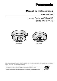
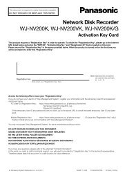
OPERATE ERROR1 ERROR2 ALARM<br />
Before attempting to connect or operate this product,<br />
please read these instructions carefully and save this manual for future use.<br />
The model number is abbreviated in some descriptions in this manual.<br />
Setup Instructions<br />
Network Video Decoder<br />
Model No. <strong>WJ</strong>-<strong>GXD400</strong><br />
<strong>WJ</strong>-<strong>GXD400</strong>/G
2<br />
CONTENTS<br />
Preface ............................................................................................................................ 3<br />
About the User Manuals .............................................................................................. 3<br />
System Requirements for a PC ................................................................................... 3<br />
Trademarks and Registered Trademarks ................................................................... 4<br />
Copyright ..................................................................................................................... 4<br />
Abbreviations .............................................................................................................. 4<br />
Network Security ......................................................................................................... 5<br />
Operation Flow ................................................................................................................ 6<br />
Setup Menu Chart ....................................................................................................... 7<br />
Network Setup ................................................................................................................. 12<br />
Network Settings of the PC ......................................................................................... 12<br />
Setup Window ................................................................................................................. 14<br />
Setup Window Call-up/Termination ............................................................................. 14<br />
Major Operating Controls and Their Functions ........................................................... 15<br />
Basic ................................................................................................................................ 16<br />
Time & date ................................................................................................................. 16<br />
Default screen ............................................................................................................. 18<br />
Language .................................................................................................................... 19<br />
Display ............................................................................................................................. 20<br />
OSD ............................................................................................................................ 20<br />
Event ............................................................................................................................... 22<br />
Site alarm .................................................................................................................... 22<br />
Error notification .......................................................................................................... 23<br />
Schedule ......................................................................................................................... 24<br />
Timetable .................................................................................................................... 24<br />
Display pattern registration ......................................................................................... 25<br />
Camera ............................................................................................................................ 26<br />
Camera Registration ................................................................................................... 26<br />
Tour sequence ............................................................................................................ 29<br />
Group sequence .......................................................................................................... 30<br />
Group setup ................................................................................................................ 31<br />
Server .............................................................................................................................. 32<br />
Proxy ........................................................................................................................... 32<br />
NTP Server ................................................................................................................. 33<br />
Network ........................................................................................................................... 34<br />
Basic Settings ............................................................................................................. 34<br />
DDNS Setup ................................................................................................................ 36<br />
User Management [User mng.] ....................................................................................... 37<br />
User authentication ..................................................................................................... 37<br />
Host authentication ..................................................................................................... 39<br />
Maintenance .................................................................................................................... 41<br />
Product Information ..................................................................................................... 41<br />
Error Log ..................................................................................................................... 42<br />
Network Log ................................................................................................................ 42<br />
Reset to the Default .................................................................................................... 44<br />
Restart this Unit ........................................................................................................... 44<br />
Viewing ............................................................................................................................ 45<br />
Live Image Reception ................................................................................................. 45<br />
Live Audio Reception .................................................................................................. 45<br />
Change of Image and Screen Pattern ......................................................................... 45<br />
Screen Pattern ............................................................................................................ 46<br />
Display Mode .............................................................................................................. 47<br />
Sequence .................................................................................................................... 47<br />
Group sequence .......................................................................................................... 48<br />
Schedule ..................................................................................................................... 48<br />
Site alarm .................................................................................................................... 49<br />
Error Notification ......................................................................................................... 49<br />
Troubleshooting ............................................................................................................... 50
Preface<br />
This unit (<strong>WJ</strong>-<strong>GXD400</strong>, <strong>WJ</strong>-<strong>GXD400</strong>/G) is an IP-network-ready decoder.<br />
This unit receives video and audio data through the IP network and provides the data to external devices such as<br />
monitors and speakers.<br />
Images from up to 6 cameras can be simultaneously displayed with this unit. For major functions, refer to the<br />
Installation Guide.<br />
Refer to "Readme.txt" on the provided CD-ROM for supported devices.<br />
About the User Manuals<br />
There are 2 sets of operating instructions for the <strong>WJ</strong>-<strong>GXD400</strong>, <strong>WJ</strong>-<strong>GXD400</strong>/G as follows.<br />
• Installation Guide: Explains how to install and connect devices.<br />
• Setup Instructions (PDF): Explains how to perform the settings of this unit using a PC via a network.<br />
Adobe ® Reader ® is required to read these operating instructions (PDF) on the provided CD-ROM.<br />
When the Adobe ® Reader ® is not installed on the PC, download the latest Adobe ® Reader ® from the Adobe web site<br />
and install it.<br />
"<strong>WJ</strong>-<strong>GXD400</strong>" or "<strong>GXD400</strong>" shown in the instructions and llustrations used in these operating instructions indicate<br />
the <strong>WJ</strong>-<strong>GXD400</strong>, <strong>WJ</strong>-<strong>GXD400</strong>/G.<br />
The screens used in these operating instructions show the case of NTSC model.<br />
Refer to "Readme.txt" on the provided CD-ROM for further information including the dedicated software, its version,<br />
and compatible cameras.<br />
System Requirements for a PC<br />
It is recommended to perform the settings of this unit using a PC that meets the following system requirements.<br />
OS: Microsoft ® Windows Vista ® Business 32-bit<br />
Microsoft ® Windows ® XP Professional SP2*<br />
Microsoft ® Windows ® XP Home Edition SP2*<br />
CPU: Pentium ® 4 3.0 GHz or faster<br />
Memory: 1 GB or more (A minimum of 512 MB memory is required when using Microsoft ® Windows ®<br />
XP.)<br />
Monitor: Resolution: 1 024 x 768 pixels or more<br />
Color: 24-bit True color or better<br />
Network interface: A 100/1 000 Mbps network interface card must be installed.<br />
Web browser: Windows ® Internet Explorer ® 7.0<br />
Microsoft ® Internet Explorer ® 6.0 SP2*<br />
Other: It is necessary to read the operating instructions and use the software on the provided CD-<br />
ROM.<br />
Adobe ® Reader ® : It is necessary to read the operating instructions on the provided CD-ROM.<br />
* Microsoft ® Internet Explorer ® 6.0 SP2 is required when using Microsoft ® Windows ® XP Home Edition SP2 or<br />
Microsoft ® Windows ® XP Professional SP2.<br />
* Microsoft® Windows® XP Professional 64-bit Edition is not supported.<br />
3
4<br />
Note:<br />
• When using a PC that does not meet the above requirements, displaying of images may become slow or the web<br />
browser may become inoperable.<br />
Trademarks and Registered Trademarks<br />
• Adobe, Adobe logo and Reader are either registered trademarks or trademarks of Adobe Systems Incorporated<br />
in the United States and/or other countries.<br />
• Microsoft, Windows, Windows Vista, Internet Explorer, ActiveX and DirectX are either registered trademarks or<br />
trademarks of Microsoft Corporation in the United States and other countries.<br />
• Intel and Pentium are trademarks or registered trademarks of Intel Corporation or its subsidiaries in the United<br />
States and other countries.<br />
• HDMI, HDMI logo and High-Definition Multimedia Interface are trademarks or registered trademarks of HDMI<br />
Licensing LLC.<br />
• Other names of companies and products contained in these operating instructions may be trademarks or registered<br />
trademarks of their respective owners.<br />
Copyright<br />
Distributing, copying, disassembling, reverse compiling, reverse engineering, and also exporting in violation of export<br />
laws of the software provided with this product, is expressly prohibited.<br />
This product incorporates copy protection technology that is protected by U.S. and foreign patents, including patent<br />
numbers 5,315,448 and 6,836,549, and other intellectual property rights. The use of Macrovision's copy protection<br />
technology in the product must be authorized by Macrovision. Reverse engineering or disassembly is prohibited.<br />
Abbreviations<br />
The following abbreviations are used in these operating instructions.<br />
Microsoft ® Windows Vista ® is described as Windows Vista.<br />
Microsoft ® Windows ® XP Professional SP2 and Microsoft ® Windows ® XP Home Edition SP2 are described as<br />
Windows XP.
Network Security<br />
As you will use this product connected to a network, your attention is called to the following security risks.<br />
• Leakage or theft of information through this product<br />
• Use of this product for illegal operations by persons with malicious intent<br />
• Interference with or stoppage of this product by persons with malicious intent<br />
It is your responsibility to take precautions such as those described below to protect yourself against the above network<br />
security risks.<br />
• Use this product in a network secured by a firewall, etc.<br />
• If this product is connected to a network that includes PCs, make sure that the system is not infected by computer<br />
viruses or other malicious entities (using a regularly updated anti-virus program, anti-spyware program, etc.).<br />
• Protect your network against unauthorized access by restricting users to those who log in with an authorized user<br />
name and password.<br />
• Apply measures such as user authentication to protect your network against leakage or theft of information,<br />
including authentication information (user names and passwords) and DDNS server information.<br />
5
6<br />
Operation Flow<br />
The operation flow of this unit is as follows.<br />
z<br />
x<br />
c<br />
v<br />
b<br />
n<br />
Rack Mounting<br />
➜<br />
Connections<br />
➜<br />
Startup<br />
➜<br />
Network settings of the PC<br />
➜<br />
Setup<br />
➜<br />
Start operation<br />
Install the unit in the rack.<br />
Refer to the Installation Guide for further information<br />
about rack mounting.<br />
If this unit is not installed in the rack, go to the step 2.<br />
Connect this unit to a PC and cameras.<br />
Refer to the provided Installation Guide for further information<br />
about connections.<br />
Turn on the power of the unit.<br />
For further information, refer to the Installation Guide.<br />
Change the TCP/IP setting of the PC to conform to the<br />
settings of this unit. (page 12)<br />
Perform the required settings on the setup menu to<br />
start operation. (page 14)<br />
Operation can be started.<br />
Images from the configured cameras are displayed.
Setup Menu Chart<br />
Performing each setting on the setup menu should be completed in advance to operate this unit.<br />
Refer to "Setup Window Call-up/Termination" (page 14) to display the setup menu.<br />
Setup items<br />
Basic<br />
Time & date<br />
Date/time display format<br />
Time display format<br />
Time & date<br />
Time zone<br />
Summer time (daylight saving)<br />
Summer time (daylight saving)<br />
table<br />
Default screen<br />
Video/Audio output settings for the<br />
default screen<br />
Description<br />
Select a date display format.<br />
Select a time display format.<br />
Adjust the current time and date.<br />
Specify the time zone.<br />
Choose whether or not to configure summer time.<br />
Specify the summer time starting year, month, day, and time,<br />
and the summer time ending year, month, day and time.<br />
Choose whether or not to automatically obtain and display<br />
images when starting up this unit.<br />
Screen pattern Select a screen pattern to be used when starting up this unit.<br />
Camera CH designation Specify which part of the screen the image obtained and displayed<br />
at startup is assigned.<br />
Audio output Choose whether or not to provide the audio output received<br />
from the camera when starting up this unit.<br />
The audio output is not provided when the compression<br />
method is set to JPEG.<br />
Language<br />
Language Select a display language for the web browser.<br />
Display<br />
OSD<br />
Camera title Specify the camera title position and adjust the position.<br />
Time & date Specify the time & date position and adjust the position.<br />
Screen ID Specify the screen ID position and adjust the position.<br />
Optional info. Specify the optional information position and adjust the position.<br />
Screen ID Enter a screen ID displayed on the small window.<br />
Time & date display Choose whether or not to display the time of this unit.<br />
Border Choose whether or not to display the border that splits the<br />
screen and select a border color.<br />
Display mode Select a display mode, either the full mode or trimming mode.<br />
Reference<br />
page<br />
16<br />
18<br />
19<br />
20<br />
7
8<br />
Setup items<br />
Event<br />
Site alarm<br />
Site alarm<br />
Choose whether or not to activate the site alarm.<br />
Originating port number<br />
Specify the port number to be used for receiving the site<br />
alarm.<br />
Alarm message display<br />
Choose whether or not to display the alarm message.<br />
Output terminal<br />
Choose whether or not to provide an alarm signal output from<br />
the output terminal when an alarm signal is received.<br />
Alarm reset timer<br />
Specify the period from alarm occurrence to alarm cancellation.<br />
Error notification<br />
Error notification Choose whether or not to enable the error notification.<br />
Destination port Specify the port number to which an error notification is transmitted<br />
when an error occurs.<br />
Retry times Specify the retry number of the transmission to the PC when<br />
transmission to the PC ends in failure.<br />
Destination address Specify the address to which an error notification is transmitted<br />
when an error occurs.<br />
Output terminal Choose whether or not to provide an alarm signal output from<br />
the output terminal when an error notification is received.<br />
Schedule<br />
Timetable<br />
Display pattern<br />
Select a display pattern from the registered patterns.<br />
Schedule Perform the settings for the schedules by designating a day of<br />
the week and time.<br />
Display pattern registration<br />
Group Select a number to be registered from the registered group<br />
numbers and group sequence numbers.<br />
Image display on a 6-screen Select a number to be registered from the registered camera<br />
numbers and tour sequence numbers.<br />
Image display on a 3-screen<br />
(PSL)<br />
Image display on a 3-screen<br />
(PSR)<br />
Description<br />
Select a number to be registered from the registered camera<br />
numbers and tour sequence numbers.<br />
Select a number to be registered from the registered camera<br />
numbers and tour sequence numbers.<br />
Image display on a 1-screen Select a number to be registered from the registered camera<br />
numbers and tour sequence numbers.<br />
Reference<br />
page<br />
22<br />
23<br />
24<br />
25
Camera<br />
NW camera setup<br />
Camera<br />
Setup items<br />
Live image source<br />
Address<br />
HTTP port<br />
User name<br />
Password<br />
Select a number assigned to the camera whose information<br />
will be registered.<br />
Obtain the information of the live image source.<br />
Enter an IP address.<br />
Enter a HTTP port number.<br />
Enter a user name.<br />
Enter a password.<br />
Recorder/Encoder (Model no.) Appears when information is obtained.<br />
Recorder/Encoder (Camera CH<br />
designation)<br />
Select a camera channel according to the specified live image<br />
source.<br />
Camera title Displays the camera title by obtaining the information when<br />
the camera title is specified. After obtaining the information,<br />
the camera title can be edited.<br />
Model no. Appears when information is obtained.<br />
Compression Select a compression method.<br />
Image capture size<br />
Select a resolution. Is selectable when the compression<br />
method is set to JPEG.<br />
Transmission interval<br />
Select an interval to update the image. Is selectable when the<br />
compression method is set to JPEG.<br />
Tour sequence<br />
Camera no. Select a registered camera.<br />
Preset camera no. (1-256) Enter the preset position of the camera to be moved at step<br />
change.<br />
Dwell time<br />
Select a dwell time.<br />
Group sequence<br />
Screen pattern Select a screen pattern.<br />
Group number Select a group number from the registered groups.<br />
Dwell time<br />
Registered pattern list<br />
Screen pattern<br />
Registered camera<br />
Server<br />
Select a dwell time.<br />
Select a screen pattern.<br />
Select a registered camera.<br />
Description<br />
Proxy<br />
Proxy Choose whether or not to use a proxy server.<br />
Server address Enter the proxy server address.<br />
Port number Enter the port number of the proxy server.<br />
Exceptions<br />
NTP<br />
Enter the IP address of the camera that does not use the<br />
proxy server.<br />
Time adjustment<br />
Select a time adjustment method for the NTP server.<br />
NTP server address Enter the IP address or host name of the NTP server.<br />
Port number Enter the port number of the NTP server.<br />
Time adjustment interval Select an interval to update the time.<br />
Reference<br />
page<br />
26<br />
29<br />
30<br />
31<br />
32<br />
33<br />
9
10<br />
Host<br />
User name<br />
Setup items<br />
Network<br />
Basic - IPv4 network<br />
Network port<br />
DHCP<br />
Choose whether or not to use DHCP.<br />
IPv4 address<br />
Specify the IP address of the IPv4 network.<br />
Subnet mask<br />
Specify the net mask in accordance with the network rules.<br />
Default gateway<br />
Maintenance port<br />
Configure the default gateway of the network.<br />
IPv4 address Specify the IP address of the IPv4 network.<br />
Subnet mask Specify the net mask in accordance with the network rules.<br />
DNS Select either automatic or manual manner to obtain the DNS<br />
server address.<br />
Primary server address Specify the DNS server address.<br />
Secondary server address<br />
HTTP port<br />
Line speed<br />
DDNS<br />
Enter the host name to be used.<br />
Enter the user name to log into the DDNS server.<br />
Password Enter the password to log into the DDNS server.<br />
Access interval Specify the interval to access the DDNS server to check the IP<br />
address and host name.<br />
User mng.<br />
User authentication<br />
User authentication<br />
User name<br />
Password<br />
Retype password<br />
Specify the DNS server address.<br />
Specify the HTTP port number.<br />
Specify the line speed for data transmission.<br />
DDNS Choose whether or not to use DDNS.<br />
Access level<br />
User check<br />
Description<br />
Choose whether or not to perform user authentication when<br />
accessing this unit.<br />
Enter a user name.<br />
Enter a password.<br />
Enter the password again to confirm the password entered<br />
into [Password].<br />
Assign the access level to the entered user name.<br />
Displays the user registered under user authentication.<br />
Host authentication<br />
Host authentication Choose whether or not to perform host authentication when<br />
accessing this unit.<br />
IP address Enter the IP address to permit accessing to this unit.<br />
Access level<br />
Assign the access level to the entered user name.<br />
Host check Displays the host (IP address) registered under host authentication.<br />
Reference<br />
page<br />
34<br />
34<br />
36<br />
37<br />
39
Setup items<br />
Maintenance<br />
Product information - Version information<br />
Software version<br />
Hardware version<br />
Product information - MAC address<br />
Displays the software version.<br />
Displays the hardware version.<br />
Description<br />
Network port<br />
Displays the MAC address of the network port.<br />
Maintenance port Displays the MAC address of the maintenance port.<br />
Product information - Serial no. Displays the serial number of the main unit.<br />
Product information - Internal thermal<br />
information<br />
Current temperature Displays the temperature inside the main unit.<br />
Highest temperature<br />
Displays the highest temperature inside the main unit recorded<br />
since turning on the power of this unit.<br />
Error log<br />
Error log<br />
Displays the error occurrence date, time, and details.<br />
Network log<br />
Network log Displays the error occurrence date, time, and details.<br />
Default reset<br />
Reset to the default (Except the Initialize the setting data.<br />
network settings)<br />
Reboot<br />
Restart this unit.<br />
Reference<br />
page<br />
41<br />
41<br />
41<br />
41<br />
41<br />
41<br />
42<br />
42<br />
44<br />
44<br />
11
12<br />
Network Setup<br />
Network Settings of the PC<br />
The TCP/IP setting of the PC shall be changed to conform to the settings of this unit. The IP address of the PC shall<br />
be specified within the same subnet range as that of the network port of this unit to access this unit.<br />
In these operating instructions, the settings are performed on Windows Vista as examples. Refer to the operating<br />
instructions of the respective OS for further information.<br />
Example:<br />
To use this unit with the default settings (IP address: 192.168.0.250), the IP address of the PC should be<br />
"192.168.0.XXX (XXX is a value between 2 and 254 except 250 (that is assigned to this unit)".<br />
1 Log in to the PC as an administrator.<br />
2 On the taskbar, click "Start", and then click the<br />
"Control Panel".<br />
The control panel will be displayed.<br />
3 Click [View network status and tasks].<br />
The "Network and Sharing Center" window will be<br />
displayed.<br />
4 Click [View status].<br />
The "Local Area Connection Status" window will be<br />
displayed.<br />
5 Click "Properties".<br />
The "Local Area Connection Properties" window will<br />
be displayed.
6 Select "Internet Protocol Version 4 (TCP/IPv4)",<br />
and then click "Properties".<br />
The "Internet Protocol Version 4 (TCP/IPv4)" window<br />
will be displayed.<br />
Note:<br />
The "User Account Control" window will be displayed<br />
depending on use or nonuse of a firewall.<br />
7 Click "Use the following IP address" and enter<br />
the IP address and the subnet mask.<br />
8 Click the "OK" button and close the window.<br />
13
14<br />
Setup Window<br />
Setup Window Call-up/Termination<br />
This unit can be operated using a web browser installed on the PC.<br />
1 Boot the PC.<br />
2 Start the web browser.<br />
3 Enter the IP address or URL assigned to this unit<br />
into the [Address] box, and then press the<br />
[Enter] key.<br />
The authentication window will be displayed.<br />
Even if "User authentication" is set to "Off", the<br />
authentication window will be displayed.<br />
Administration authentication is required to display<br />
the setup window.<br />
Important:<br />
• Refer to a system administrator for the set IP<br />
address of this unit.<br />
• If "Host authentication" is set to "On" (page 39), this<br />
unit cannot be accessed from the PC whose IP<br />
address has not been registered with this unit.<br />
Refer to a system administrator for further information.<br />
• Do not attach "0" before the numbers when entering<br />
IP address.<br />
Example:<br />
b 192.168.0.50<br />
× 192.168.0.050<br />
4 Enter the user name and password registered on<br />
this unit. Click the [Login] button.<br />
The top page will be displayed.<br />
Important:<br />
• Refer to a system administrator for the set user<br />
name and password.<br />
• Refer to page 37 for the descriptions of how to register<br />
users.<br />
• The default user name and password are as follows.<br />
User name: admin<br />
Password: 12345<br />
• To enhance the security, change the password for<br />
an administrator before running the unit. It is recommended<br />
to change the password for the administrator<br />
periodically. Refer to page 37 for descriptions of<br />
how to change the password.<br />
• When the unit is being operated without changing<br />
the user name and password, the pop-up window<br />
saying that it is recommended to change the password<br />
will be displayed.
Major Operating Controls and Their Functions<br />
Top Page<br />
q<br />
w<br />
e<br />
r<br />
t<br />
y<br />
u<br />
i<br />
o<br />
q [Basic] button<br />
Performs the image and audio settings at time display<br />
or startup.<br />
w [Display] button<br />
Performs the settings relating to OSD.<br />
e [Event] button<br />
Performs the action settings at event occurrence.<br />
r [Schedule] button<br />
Performs the schedule settings to display images.<br />
t [Camera] button<br />
Performs the settings relating to the network such as<br />
the camera IP addresses and port numbers and the<br />
settings of the sequential display.<br />
y [Server] button<br />
Performs the settings relating to the proxy and NTP<br />
servers.<br />
u [Network] button<br />
Performs the network settings such as settings of<br />
the IP address of this unit and gateway address.<br />
i [User mng.] button<br />
Performs the settings for the user authentication/<br />
host authentication to restrict access this unit from<br />
PCs.<br />
o [Maintenance] button<br />
Displays and initializes the information of this unit.<br />
15
16<br />
Basic<br />
Perform the settings for the basic operations of this unit.<br />
Time & date<br />
The settings of date and time are performed.<br />
1 Click the [Basic] button on the setup menu.<br />
2 Click the [Time & date] tab.<br />
The "Time & date" window will be displayed.<br />
Setup items<br />
■ Date/time display format<br />
Select a date format to be displayed from the following.<br />
Example: (Ex. April 1, 2009)<br />
DD/MM/YYYY: 01/04/2009<br />
MM/DD/YYYY: 04/01/2009<br />
DD/Mmm/YYYY: 01/Apr/2009<br />
YYYY/MM/DD: 2009/04/01<br />
Mmm/DD/YYYY: Apr/01/2009<br />
Default: Mmm/DD/YYYY (NTSC model)<br />
DD/MM/YYYY (PAL model)<br />
■ Time display format<br />
Select a time display format to be displayed from the following.<br />
(Example for 3 o’clock in the afternoon)<br />
12h: 03:00:00PM<br />
24h: 15:00:00<br />
Default: 12h (NTSC model)<br />
24h (PAL model)<br />
3 Perform the settings for each item.<br />
Refer to the following for further information about<br />
the settings for each item.<br />
4 Click the [Set] button.<br />
■ Time & date<br />
Adjust the current time and date.<br />
Select numbers for year, month, day, hour, minute and<br />
second, and click the [Set] button. This unit operates<br />
with the adjusted time from the moment of clicking.<br />
2009-2035 (year)<br />
/01-12 (month)<br />
/01-31 (day)<br />
/00-23 (hour)<br />
/00-59 (minute)<br />
/00-59 (second)<br />
■ Time zone<br />
Select the time zone of this unit.<br />
■ Summer time (daylight saving)<br />
Perform the settings for summer time from the following.<br />
Out: Does not function.<br />
Auto: Applies summer time in accordance with the setting<br />
of summer time. During summertime, the time<br />
will be displayed with an asterisk (*).<br />
Default: Auto
■ Summer time (daylight saving) table<br />
Set the start (On)/end (Off) date and time for summer<br />
time.<br />
When the [Setup >>] button is clicked the following window<br />
will be displayed.<br />
• Specify the summer time start date and time at [In]<br />
and summer time end date and time at [Out].<br />
• Up to 10 times and dates for switching to summer<br />
time can be set.<br />
• Click the [Set] button after completing the settings,<br />
and close the window by clicking the [×] button at the<br />
top right of the window.<br />
17
18<br />
Default screen<br />
The video and audio outputs can be automatically obtained at starting this unit.<br />
1 Click the [Basic] button on the setup menu.<br />
2 Click the [Default screen] tab.<br />
The "Default screen" window will be displayed.<br />
Setup items<br />
■ Video/Audio output settings for the default screen<br />
Determine whether or not to automatically obtain and<br />
display images when starting up this unit.<br />
Apply the below settings: Selection of the screen pattern<br />
and camera allows user to obtain and display<br />
the configured image at starting this unit.<br />
Maintain the previous operational state: The camera<br />
image displayed immediately before restarting this<br />
unit is obtained and displayed.<br />
No output:<br />
Default: Maintain the previous operational state<br />
■ Screen pattern<br />
Select a screen pattern to be used when starting up this<br />
unit.<br />
6-screen/3-screen (primary screen on the left)/3-screen<br />
(primary screen on the right)/1-screen<br />
Default: 6-screen<br />
■ Camera CH designation<br />
Specify which part of the screen the image obtained and<br />
displayed at startup is assigned.<br />
Select cameras whose images are to be displayed at<br />
the image display positions 1 to 6.<br />
3 Perform the settings for each item.<br />
Refer to the following for further information about<br />
the settings for each item.<br />
4 Click the [Set] button.<br />
■ Audio output<br />
Select "On" or "Off" to determine whether or not to output<br />
the audio.<br />
Important:<br />
• The audio output is not provided when the compression<br />
method is set to JPEG. The audio output is provided<br />
only at the default screen.<br />
• When the screen is split, the audio output is provided<br />
from the camera assigned to the image display<br />
position 1.<br />
Notes:<br />
• Camera registration should be completed via<br />
[Camera] and [NW camera] before camera selection.<br />
• The audio output is available only from our<br />
(Panasonic i-pro series) cameras.<br />
• The audio output is provided only if the audio output<br />
setting has been performed at the camera side.<br />
• The schedule setting has higher priority if the schedule<br />
setting has been performed.<br />
• Audio output and image output may sometimes not<br />
be synchronized depending on the data (audio and<br />
image) reception timing.
Language<br />
Select the display language for the web browser from<br />
the following.<br />
3 Perform the settings for each item.<br />
Refer to the following for further information about<br />
the settings for each item.<br />
4 Click the [Set] button.<br />
1 Click the [Basic] button on the setup menu.<br />
2 Click the [Language] tab.<br />
The "Language" window will be displayed.<br />
19
20<br />
Display<br />
OSD<br />
The settings of information displayed on the screen are performed in this section.<br />
1 Click the [Display] button on the setup menu.<br />
2 Click the [OSD] tab.<br />
The "OSD" window will be displayed.<br />
Setup items<br />
■ OSD position<br />
[Camera title]<br />
Select a camera title position from the following.<br />
Position: Off/Upper left/Upper right/Lower left/Lower<br />
right<br />
Default: Off<br />
Adjustment: --/+1/+2/+3/+4/-1/-2/-3/-4<br />
Default: --<br />
[Time & date]<br />
Select a date and time position from the following:<br />
Position: Off/Upper left/Upper right/Lower left/Lower<br />
right<br />
Default: Off<br />
Adjustment: --/+1/+2/+3/+4/-1/-2/-3/-4<br />
Default: --<br />
Note:<br />
• If the date and time information is not provided from<br />
the camera, even selecting other than "Off" does not<br />
display date and time.<br />
[Screen ID]<br />
The settings of the screen ID in detail are performed on<br />
the "Screen ID setup" window. (Page 21)<br />
Position: Off/Upper left/Upper right/Lower left/Lower<br />
right<br />
3 Perform the settings for each item.<br />
Refer to the following for further information about<br />
the settings for each item.<br />
4 Click the [Set] button.<br />
Default: Off<br />
Adjustment: --/+1/+2/+3/+4/-1/-2/-3/-4<br />
Default: --<br />
[Optional info.]<br />
Select an optional information position from the following.<br />
Position: Off/Upper left/Upper right/Lower left/Lower<br />
right<br />
Default: Off<br />
Adjustment: --/+1/+2/+3/+4/-1/-2/-3/-4<br />
Default: --<br />
Note:<br />
• The sequence number is displayed during sequential<br />
display.<br />
■ Time & date display<br />
Select "On" or "Off" to determine whether or not to display<br />
the time and date of this unit.<br />
Default: On<br />
■ Border<br />
Select a color of the screen splitting border from the following.<br />
Off/Black/Gray/White<br />
Default: Off
■ Display mode<br />
Select either the "Full screen" or "Trimmed screen".<br />
When the display mode is toggled, restart this unit.<br />
If edges of an image are chipped in the full screen,<br />
change the mode to the trimmed screen.<br />
Default: Full screen<br />
Important:<br />
• If the time & date or border is always displayed, the<br />
screen is susceptible to burn-in. Therefore, setting<br />
the time & date or border to Off is recommended.<br />
[Screen ID]<br />
A screen ID can be assigned to each split screen and<br />
displayed.<br />
1 Click the [Display] button on the setup menu.<br />
2 Click the [OSD] tab in the setup menu.<br />
The "OSD" window will be displayed.<br />
3 Click the [Setup >>] tab in "Screen ID >>".<br />
Refer to the following for further information about<br />
the settings for each item.<br />
Setup items<br />
■ 6-screen<br />
Select an information position to be displayed on the<br />
screen.*<br />
■ 3-screen(primary screen on the left)<br />
Select an information position to be displayed on the<br />
screen.*<br />
Notes:<br />
• Displayed characters may be overlapped depending<br />
on the displayed position settings. If characters are<br />
overlapped, the pop-up window is displayed.<br />
• Check whether full resolution is available with the<br />
connected monitor.<br />
4 Click the [Set] button in "Screen ID setup".<br />
■ 3-screen(primary screen on the right)<br />
Select an information position to be displayed on the<br />
screen.*<br />
■ 1-screen<br />
Select an information position to be displayed on the<br />
screen.*<br />
* Up to 4 alphanumeric characters can be entered.<br />
21
22<br />
Event<br />
When an event signal (alarm notification) is received from another network device, an alarm action starts in accordance<br />
with the setting.<br />
Site alarm<br />
The alarm action at site alarm occurrence can be specified.<br />
1 Click the [Event] button on the setup menu.<br />
2 Click the [Site alarm] tab.<br />
The "Site alarm" window will be displayed.<br />
Setup items<br />
■ Site alarm<br />
Select "On" or "Off" to determine whether or not to activate<br />
the site alarm.<br />
■ Originating port number<br />
Specify the port number to receive the site alarm signal.<br />
Default: 1818<br />
■ Alarm message display<br />
Select "On" or "Off" to determine whether or not to display<br />
the message to notify event occurrence.<br />
■ Output terminal<br />
Select "On" or "Off" to determine whether or not to provide<br />
the alarm signal output at event occurrence.<br />
■ Alarm reset timer<br />
Select the period to cancel the alarm action.<br />
Off/10s/20s/30s/1min/5min<br />
Default: 20s<br />
3 Perform the settings for each item.<br />
Refer to the following for further information about<br />
the settings for each item.<br />
4 Click the [Set] button.
Error notification<br />
When an error occurs, the setting to send the message to the previously registered addresses is performed.<br />
Up to 3 destinations of notification can be registered.<br />
1 Click the [Event] button on the setup menu.<br />
2 Click the [Error notification] tab.<br />
The "Error notification" window will be displayed.<br />
Setup items<br />
■ Error notification<br />
Select "On" or "Off" to determine whether or not to activate<br />
the transmission of error notification.<br />
■ Destination port<br />
Specify the port number to which an error notification is<br />
transmitted when an error occurs.<br />
Default: 8181<br />
■ Retry times<br />
Select the retry number of the transmission to the PC<br />
from the following.<br />
1/2/3 ...29/30<br />
Default: 2<br />
■ Destination address 1 - 3<br />
Specify the address to which an error notification is<br />
transmitted when an error occurs.<br />
However, the following addresses are not available to<br />
register as a destination of error notification.<br />
0.XXX.XXX.XXX/XXX.XXX.XXX.0/XXX.XXX.XXX.255/<br />
127.0.0.1<br />
• Class D address (224.0.0.0 - 239.255.255.255)<br />
• Class E address (240.0.0.0 - 255.255.255.255)<br />
3 Perform the settings for each item.<br />
Refer to the following for further information about<br />
the settings for each item.<br />
4 Click the [Set] button.<br />
■ Output terminal<br />
Select "On" or "Off" to determine whether or not to provide<br />
the error notification signal output at error occurrence<br />
with this unit.<br />
23
24<br />
Schedule<br />
The schedule setting is performed in accordance with the specified day of the week and time of the day.<br />
It is possible to switch camera channels to be used to display images according to the set schedule.<br />
Important:<br />
• The audio output is not provided when the "Schedule" window is displayed for setup. The audio output is provided<br />
only at the default screen.<br />
Timetable<br />
Timetables are created for each day of the week, and a program is assigned to each timetable. Up to 6 timetables<br />
can be created for each day of the week.<br />
1 Click the [Schedule] button on the setup menu.<br />
2 Click the [Timetable] tab.<br />
The "Timetable" window will be displayed.<br />
Setup items<br />
■ Display pattern<br />
Select a registered display pattern from the following.<br />
--/Display pattern 1/Display pattern 2/Display pattern<br />
3/Display pattern 4<br />
Default: --<br />
■ Schedule<br />
Perform the settings for the schedules by designating a<br />
day of the week and time.<br />
Up to 6 schedule settings can be performed.<br />
• Day unspecified: Check the "24h" checkbox.<br />
3 Perform the settings for each item.<br />
Up to 6 schedule settings can be performed.<br />
Refer to the following for further information about<br />
the settings for each item.<br />
4 Click the [Set] button.<br />
Notes:<br />
• Before display pattern selection, register the display<br />
pattern via [Schedule] and [Display pattern registration].<br />
• Be sure to perform each schedule setting between<br />
00:00 and 24:00.<br />
• If two or more schedules coincide, a higher numbered<br />
schedule has a higher priority.<br />
• The entered 1-week schedule is displayed with a<br />
band chart below the [Set] button.<br />
• Even when it passed time of a timetable of the set<br />
schedule, displaying of images will continue according<br />
to the setting of the previous schedule until other<br />
schedule start displaying images.
Display pattern registration<br />
1 Click the [Schedule] button on the setup menu.<br />
2 Click the [Display pattern registration] tab.<br />
The "Display pattern registration" window will be displayed.<br />
3 Click the [Setup >>] button of [Pattern no.].<br />
The [Pattern no.: b] window of [Display pattern registration]<br />
will be displayed.<br />
Setup items<br />
■ Group<br />
Select from the registered group numbers and group<br />
sequence numbers.<br />
Note:<br />
• Before selecting "Group setup", configure the settings<br />
of "Group setup" under "Camera" to register<br />
cameras as a group. When selecting "Group<br />
sequence", configure also the settings of "Group<br />
sequence" under "Camera" to register group<br />
sequences.<br />
■ Image display on a 6-screen<br />
Select cameras whose images are displayed on split<br />
screens.<br />
4 Perform the settings for each item.<br />
Determine whether to display images from cameras<br />
registered as a group or from the selected cameras.<br />
Configure the settings for the selected setting item.<br />
Refer to the following for further information about<br />
the settings for each item.<br />
5 Click the [Set] button.<br />
■ Image display on a 3-screen (PSL)<br />
■ Image display on a 3-screen (PSR)<br />
■ Image display on a 1-screen<br />
Select cameras whose images are displayed on split<br />
screens.<br />
Note:<br />
• Before selecting cameras independently, configure<br />
the settings of "Camera registration" under "Camera"<br />
to register cameras. When selecting "Tour<br />
sequence", configure also the settings of "Tour<br />
sequence" under "Camera" to register tour<br />
sequences.<br />
25
26<br />
Camera<br />
The network settings (such as address and port number) of cameras, group settings, and the settings of sequential<br />
display are performed in this section.<br />
Camera Registration<br />
Registration and change of the network camera are performed. The list of the registered cameras is shown. In addition,<br />
the camera settings relating to the network such as IP address and port number are performed.<br />
1 Click the [Camera] button on the setup menu.<br />
2 Click the [NW camera] tab.<br />
The "Registered camera list" window will be displayed.<br />
Refer to "Registered camera list" for the displayed<br />
contents.<br />
3 Select the radio button of the camera number to<br />
be registered.<br />
4 Click the [Set] button.<br />
The "NW camera setup" window will be displayed.<br />
5 Perform the settings for each item.<br />
Refer to the "NW camera setup" for information on<br />
how to configure the settings.<br />
6 Click the [Information inquiry] button.<br />
The information of the specified live image source is<br />
obtained.<br />
Refer to the "Information inquiry list" for information<br />
on how to configure the settings.<br />
Not all information can be obtained. Perform additional<br />
settings if necessary.<br />
7 Click the [Set] button.<br />
Note:<br />
When the settings of the camera is edited after<br />
obtaining information, images may sometimes not<br />
be displayed correctly. In this case, obtain information<br />
again.
Setup items<br />
■ Registered camera list<br />
[Camera no.]<br />
Displays the camera number. Up to 256 cameras can<br />
be registered.<br />
[Camera title]<br />
Displays the registered camera titles.<br />
[Model no.]<br />
Displays the model number of the registered<br />
camera/encoder.<br />
[Address]<br />
Displays the IP address of the registered<br />
camera/encoder.<br />
When "Via a recorder" is selected for "Live image<br />
source", the IP address of the recorder will be displayed.<br />
Note:<br />
• To delete the information, select the camera number<br />
and click the [Delete] button.<br />
■ NW camera setup<br />
[Camera]<br />
Select a camera number whose information is registered.<br />
[Live image source]<br />
Select a live image source.<br />
From a camera directly/Encoder/Via a recorder<br />
Default: From a camera directly<br />
[Address]<br />
Enter the IP address of the live image source.<br />
[HTTP port]<br />
Enter a HTTP port number.<br />
Default: 80<br />
[User name]<br />
Enter the user name assigned to the device of a live<br />
image source when user authentication is set to "On" at<br />
the device.<br />
Enter up to 32 alphanumeric characters.<br />
[Password]<br />
Enter the password assigned to the device of a live<br />
image source when user authentication is set to "On" at<br />
the device.<br />
Enter up to 32 alphanumeric characters.<br />
Important:<br />
• When using a camera other than Panasonic i-pro<br />
series, select "Via a recorder" for "Live image<br />
source". In this case, select "JPEG" for<br />
"Compression".Refer to the operating instructions of<br />
the recorder in use for further information on how to<br />
configure the settings of the recorder.<br />
■ Information list<br />
[Model no. (Recorder/Encoder)]<br />
Displays the model number of the recorder or encoder.<br />
[Camera CH designation (Recorder/Encoder)]<br />
Select camera channels of the device used as a live<br />
image source.<br />
[Camera title]<br />
Displays the camera title after obtaining the information<br />
if the camera title is assigned to the target device.<br />
This item can be entered and edited.<br />
Up to 16 characters in one byte/two bytes<br />
[Model no.]<br />
Displays the model number after information is<br />
obtained. When routed through the recorder, the model<br />
number of the camera/encoder connected ahead. When<br />
the camera is directly connected, the model number of<br />
the camera is displayed.<br />
[Compression]<br />
Select a compression method. The selectable compression<br />
method varies with the model of the camera whose<br />
information is obtained. When routed through the<br />
recorder, the compression method is decided depending<br />
on the device of the information source.<br />
The compression method is selectable from the following:<br />
JPEG/MPEG-4/H.264<br />
27
28<br />
[Image capture size*]<br />
Select an image capture size. Image capture size can<br />
be selected only when "JPEG" is selected for<br />
"Compression".<br />
Default: Auto<br />
[Transmission interval]<br />
Select a transmission interval when the compression<br />
method is set to JPEG.<br />
The higher the value of ips (images per second) is, the<br />
shorter the transmission interval is.<br />
Auto/0.1ips/0.2ips/0.3ips/0.5ips/1ips/2ips/3ips/<br />
5ips/10ips/15ips/30ips<br />
Default: Auto<br />
For NP472/NW474/NS320 (NTSC model), the transmission<br />
interval is selectable from the following:<br />
Auto/1ips/ 2ips/3ips/5ips/10ips/15ips/30ips<br />
Default: Auto<br />
Important:<br />
• When "Via a recorder" is selected for "Live image<br />
source", the image capture size and the refresh<br />
interval will be dependent on the settings of the camera.<br />
The settings configured on the decoder will not<br />
be applied. Confirm that the settings of the recorder<br />
and the camera.<br />
• When camera images via the recorder are displayed<br />
in the VGA size, the resolution of the camera shall<br />
be set to "VGA" or "QVGA".<br />
* The resolution is selectable from the following:<br />
Auto/QVGA(320x240)/VGA(640x480)/768x576 /4<br />
VGA(1280x960)<br />
Auto: Select a resolution in accordance with the<br />
screen size.<br />
QVGA(320x240): 320 x 240 pixels resolution<br />
VGA(640x480): 640 x 480 pixels resolution<br />
768x576: 768 x 576 pixels resolution<br />
4VGA(1280x960): 1280 x 960 pixels resolution<br />
The resolution varies with the model of the camera.<br />
Notes:<br />
• All options are displayed when the compression<br />
method supported by the target device is unknown.<br />
• Images with the resolution of 4 VGA (1280 x 960)<br />
cannot be displayed in the reduced size of VGA (640<br />
x 480).<br />
• When trying to display images from a camera that<br />
can transmit two streams of H.264 or MPEG-4, this<br />
unit will automatically select either of streams<br />
according to the resolution setting. When the same<br />
resolution is set for both streams on the camera,<br />
stream 1 will automatically be selected.
Tour sequence<br />
Camera images are automatically switched and displayed in a specified order.<br />
The tour sequence function works with the preset positions of the camera.<br />
Important:<br />
• The audio output is not provided during the sequential display.<br />
• When a sequence is performed with two or more devices, the JPEG and MPEG-4 formats shall not be used<br />
simultaneously with one camera.<br />
1 Click the [Camera] button on the setup menu.<br />
2 Click the [Tour sequence] tab.<br />
The "Tour sequence number" window will be displayed.<br />
Setup items<br />
■ Step<br />
Displays the step number of the sequence. Up to 64<br />
steps can be contained.<br />
■ Camera no.<br />
Select a registered camera.<br />
■ Preset camera no. (1-256)<br />
Enter a preset position number (blank, 1 to 256).<br />
3 Click the [Setup >>] button.<br />
The "Step registration" window will be displayed.<br />
4 Perform the settings for each item.<br />
Refer to the following for further information about<br />
the registrations for each item.<br />
5 Click the [Set] button.<br />
When no preset position number is entered (blank), the<br />
camera does not move to any preset position.<br />
■ Dwell time<br />
Select an interval time to go to the next sequential step<br />
from the following.<br />
3s/5s/10s/15s/20s<br />
Default: 3s<br />
29
30<br />
Group sequence<br />
Live images from the camera/encoder/recorder on all the screens are simultaneously switched and displayed in the<br />
3-screen/6-screen modes. The camera preset position cannot be selected during the group sequence.<br />
1 Click the [Camera] button on the setup menu.<br />
2 Click the [Group sequence] tab.<br />
The "Group sequence number" window will be displayed.<br />
Setup items<br />
■ Screen pattern<br />
Select a screen pattern.<br />
6-screen/3-screen (primary screen on the left)/3-screen<br />
(primary screen on the right)<br />
■ Step<br />
Displays the step number of the sequence. Up to 64<br />
steps can be contained.<br />
■ Group number<br />
Displays the registered camera group number.<br />
3 Click the [Setup >>] button.<br />
The "Step registration" window will be displayed.<br />
4 Perform the settings for each item.<br />
Refer to the following for further information about<br />
the registrations for each item.<br />
5 Click the [Set] button.<br />
The specified values are stored.<br />
■ Dwell time<br />
Select an interval time to go to the next sequential step<br />
from the following.<br />
3s/5s/10s/15s/20s<br />
Note:<br />
• Group registration should be completed via<br />
[Camera] and [Group setup] before group number<br />
selection.
Group setup<br />
1 Click the [Camera] button on the setup menu.<br />
2 Click the [Group] tab.<br />
The "Group setup" window will be displayed.<br />
Setup items<br />
■ Group number<br />
Display a group number.<br />
■ Screen pattern<br />
Select a screen pattern.<br />
■ Registered camera - Image display position 1 - 6<br />
Assign the registered cameras to the display positions<br />
1-6 on the screen.<br />
■ Delete<br />
Check the boxes of the group number to be deleted.<br />
Click the [Delete] button.<br />
To apply the deletion to the registered information, click<br />
the [Set] button.<br />
3 Click the [Registered pattern list] button.<br />
The "Registered pattern list" window will be displayed.<br />
4 Perform the settings for each item.<br />
Refer to the following for further information about<br />
the settings for each item.<br />
5 Click the [Set] button.<br />
Note:<br />
• To view the image display position from the configured<br />
camera, see the reference information displayed<br />
below [Registered group list].<br />
• When "Group Sequence" is selected, a camera<br />
image is displayed only in 1 position even though<br />
the camera CH is set to display the images in more<br />
than 1 position.<br />
• Images with the resolution of 4 VGA (1280 x 960)<br />
cannot be displayed in the reduced size of VGA<br />
(640 x 480).<br />
31
32<br />
Server<br />
Proxy<br />
The proxy server settings can be performed with this menu.<br />
1 Click the [Server] button on the setup menu.<br />
2 Click the [Proxy] tab.<br />
The "Proxy" window will be displayed.<br />
Setup items<br />
■ Proxy setup use<br />
Select "On" or "Off" to determine whether or not to use<br />
the proxy server.<br />
When "On" is selected, perform the following settings.<br />
■ Server address<br />
Enter the server name or IP address of the proxy server.<br />
*1<br />
When entering a server name, it is necessary to use a<br />
DNS.<br />
Up to 255 alphanumeric characters including hyphens<br />
(-) and periods (.) can be entered.<br />
*1The entry rules for the proxy server are shown below.<br />
• At IPv4 entry<br />
XXX.XXX.XXX.XXX (XXX indicates a value from 0<br />
to 255.)<br />
However, the following addresses are not available.<br />
• 0.XXX.XXX.XXX/XXX.XXX.XXX.0/<br />
XXX.XXX.XXX.255/127.0.0.1<br />
• Class D address (224.0.0.0 - 239.255.255.255)<br />
• Class E address (240.0.0.0 - 255.255.255.255)<br />
3 Perform the settings for each item.<br />
Refer to the following for further information about<br />
the settings for each item.<br />
4 Click the [Set] button.<br />
■ Port number<br />
Enter a port number of a proxy server.<br />
■ Exceptions<br />
Enter the set address of the network camera.Enter the<br />
IP address of the excluded camera.<br />
Up to 128 alphanumeric characters including asterisks<br />
(*), semicolons (;) and periods (.) can be entered.<br />
A semicolon (;) is used for dividing the addresses.<br />
Entering "*" validates all numbers.
NTP Server<br />
When time is adjusted with reference to the NTP (Network Time Protocol) server, the settings in this section are performed.<br />
1 Click the [Server] button on the setup menu.<br />
2 Click the [NTP] tab.<br />
The "NTP" window will be displayed.<br />
Setup items<br />
■ Time adjustment<br />
Select a time adjustment method.<br />
Manual: Manual adjustment<br />
Synchronization with NTP server: Adjustment with use<br />
of the NTP server<br />
Default: Manual<br />
■ NTP server address<br />
Enter the IP address or host name for the NTP server.<br />
When entering a server name, it is necessary to use a<br />
DNS.<br />
The entry rules for the NTP server are shown below.<br />
• At IPv4 entry<br />
XXX.XXX.XXX.XXX (XXX indicates a value from 0<br />
to 255.)<br />
However, the following addresses are not available.<br />
• 0.XXX.XXX.XXX/XXX.XXX.XXX.0/<br />
XXX.XXX.XXX.255/127.0.0.1<br />
• Class D address (224.0.0.0 - 239.255.255.255)<br />
• Class E address (240.0.0.0 - 255.255.255.255)<br />
3 Perform the settings for each item.<br />
Refer to the following for further information about<br />
the settings for each item.<br />
4 Click the [Set] button.<br />
■ NTP Port<br />
Enter a port number of the NTP server.<br />
Default: 123<br />
■ Time adjustment interval<br />
Select an interval to update the time from the following.<br />
1h/2h/3h.....23h/24h<br />
Default: 1h<br />
33
34<br />
Network<br />
Basic Settings<br />
The network configuration for this unit is performed.<br />
1 Click the [Network] button on the setup menu.<br />
2 Click the [Basic] tab.<br />
The "IPv4 network" window will be displayed.<br />
Setup items<br />
■ IPv4 network - Network port<br />
[DHCP]<br />
Select "On" or "Off" to determine whether or not to use<br />
the DHCP function.<br />
Default: Off<br />
[IPv4 address]<br />
Enter an IP address when "Off" is selected for "DHCP".<br />
Default: 192.168.0.250<br />
[Subnet mask]<br />
Enter a subnet mask according to the network configuration<br />
when "Off" is selected for "DHCP".<br />
Default: 255.255.255.0<br />
[Default gateway]<br />
Enter the IP address of the gateway according to the<br />
network environment when "Off" is selected for "DHCP".<br />
Default: 192.168.0.1<br />
3 Perform the settings for each item.<br />
Refer to the following for further information about<br />
the settings for each item.<br />
4 Click the [Set] button.<br />
■ Maintenance port<br />
[IPv4 address]<br />
Enter an IP address.<br />
Default: 192.168.2.250<br />
[Subnet mask]<br />
Enter a subnet mask.<br />
Default: 255.255.255.0<br />
[DNS]<br />
Select "Manual" or "Auto" to enable IP address searching<br />
by the host name using the DNS.<br />
Selecting "Auto" is available only when "On" is selected<br />
for "DHCP" (using the DHCP server).<br />
When "Manual" is selected for the DNS, enter the DNS<br />
server addresses in "Primary server address" and<br />
"Secondary server address".<br />
[Primary server address]<br />
Enter the IP address of the primary DNS server.<br />
[Secondary server address]<br />
Enter the IP address of the secondary DNS server.
[HTTP port]<br />
A number from 1 - 65535 is available. Under normal<br />
conditions, assign 80 to the number.<br />
Default: 80<br />
Notes:<br />
• Depending on the network settings of the LAN or<br />
Internet service provider, network communication<br />
may not be established if the http port number has<br />
been changed. In this case, refer to the administrator<br />
of the network.<br />
• The following port numbers and the port numbers<br />
used for the site alarm settings are unavailable for<br />
the HTTP port number.<br />
20, 21, 23, 25, 42, 53, 67, 68, 69, 110, 123, 161,<br />
162, 995, 10669, 10670<br />
[Line speed]<br />
The following are available for "Line speed".<br />
Auto/1000M-Full/100M-Full/100M-Half/10M-Full/<br />
10M-Half<br />
Default: Auto<br />
Important:<br />
• The network settings for each port (network<br />
port/maintenance port) should be configured with a<br />
different subnet.<br />
35
36<br />
DDNS Setup<br />
The settings are performed to use the DDNS (Dynamic Domain Name System).<br />
Use of the DDNS function provides access with "The host name registered with the DDNS server. nmdns.net". To<br />
receive the service, connection to the dedicated server is required.<br />
1 Click the [Network] button on the setup menu.<br />
2 Click the [DDNS] tab.<br />
The "DDNS" window will be displayed.<br />
Setup items<br />
■ DDNS<br />
Select "On" or "Off" to determine whether or not to use<br />
the DDNS (Dynamic Domain Name Server).<br />
When "On" is selected, perform the following settings.<br />
Default: Off<br />
■ Host name<br />
Enter a host name registered in the DDNS.<br />
Enter up to 64 alphanumeric characters including<br />
hyphens (-) and periods (.).<br />
■ User name<br />
Enter a user name registered in the DDNS.<br />
Enter up to 32 alphanumeric or symbolic characters<br />
except for colons (:) and semicolons (;).* 1<br />
■ Password<br />
Enter a password respective to the entered user name.<br />
Enter up to 32 alphanumeric characters. *1<br />
3 Perform the settings for each item.<br />
Refer to the following for further information about<br />
the settings for each item.<br />
4 Click the [Set] button.<br />
■ Access interval<br />
Select an interval to update the DNS from the following:<br />
1min/10min/30min/1h/6h/24h<br />
Default: 1h<br />
*1 The following alphanumeric characters can be<br />
entered.<br />
A B C D E F G H I J K L M N O P Q R S T U V W X<br />
Y Z a b c d e f g h i j k l m n o p q r s t u v w x y z 0 1<br />
2 3 4 5 6 7 8 9 ! " # $ % ' ( ) * + , - . / :; < = > ? @ [ \ ]<br />
^ _ ` { | } ~
User Management [User mng.]<br />
The settings for the user authentication/host authentication are performed to restrict access this unit from PCs.<br />
It is possible to restrict access this unit from users/hosts (PCs) by registering users and hosts (PCs) who can access<br />
this unit in advance when "On" is selected for the user authentication and the host authentication.<br />
User authentication<br />
The information settings (change of user name and password, access level, etc.) of the user that operates this unit<br />
are performed.<br />
Up to 32 user information entries can be registered.<br />
1 Click the [User mng.] button on the setup menu.<br />
2 Click the [User authentication] tab.<br />
The "User authentication" window will be displayed.<br />
Setup items<br />
■ User authentication<br />
Select "On" or "Off" to determine whether or not to<br />
authenticate the user.<br />
■ User name<br />
Enter a user name.<br />
Enter up to 32 alphanumeric characters.<br />
■ Password<br />
Enter a password.<br />
Enter 4 to 32 alphanumeric characters for a password.<br />
Notes:<br />
• Set a unique password, not something that would be<br />
easily guessed by a third person. The password also<br />
should be memorable.<br />
• To enhance the security, change the password for<br />
an administrator periodically.<br />
3 Perform the settings for each item.<br />
The user name, password, password confirmation,<br />
and access level can be specified.<br />
Refer to the following for further information about<br />
the settings for each item.<br />
4 Click the [Set] button after completing the settings.<br />
5 If user registration is continued, repeat the steps<br />
3 and 4.<br />
6 Select "On" or "Off" to determine whether or not<br />
to authenticate the user.<br />
Refer to the following for further information about<br />
the settings for each item.<br />
7 Click the [Set] button.<br />
■ Retype password<br />
Reenter the password entered into [Password].<br />
■ Access level<br />
Select an access level.<br />
Users whose access level is "Administrator" can access<br />
the setup menu.<br />
The settings for "Live image display" are for functions<br />
that are not described in these operating instructions<br />
and they are for expansion of external control interface.<br />
It is impossible to access to the setup menu of these<br />
functions.<br />
1. Administrator/2. Live only<br />
Default: 2. Live only<br />
37
38<br />
■ User check<br />
It is possible to check the user names registered for the<br />
user authentication.<br />
To delete the displayed user, click the [Delete] button.<br />
Important:<br />
• When the user name already in use is selected and<br />
the [Set] button is clicked, it will be overwritten.<br />
Deletion of user information [User check]<br />
1 Click the [User mng.] button on the setup menu.<br />
2 Click the [User authentication] tab.<br />
The "User authentication" window will be displayed.<br />
3 Click the [C] button in "User check".<br />
The user name registered under user authentication<br />
can be viewed.<br />
4 Click the [Delete] button.<br />
The user selected in "User check" can be deleted.
Host authentication<br />
The information of a PC (host) is registered, which accesses this unit via a network such as a LAN.<br />
Up to 32 hosts can be registered.<br />
1 Click the [User mng.] button on the setup menu.<br />
2 Click the [Host authentication] tab.<br />
The "Host authentication" window will be displayed.<br />
Setup items<br />
■ Host authentication<br />
Select "On" or "Off" to determine whether or not to<br />
authenticate the host.<br />
■ IP address<br />
Enter the IP address to permit accessing to this unit.<br />
The host name cannot be specified.<br />
■ Access level<br />
Select an access level. The setup window can be<br />
accessed through the host with the administrator level.<br />
The settings for "Live image display" are for functions<br />
that are not described in these operating instructions<br />
and they are for expansion of external control interface.<br />
It is impossible to access to the setup menu of these<br />
functions.<br />
1. Administrator/2. Live only<br />
Default: 2. Live only<br />
3 Perform the settings for each item.<br />
Set the IP address and the access level.<br />
Refer to the following for further information about<br />
the settings for each item.<br />
4 Click the [Set] button.<br />
5 Select "On" or "Off" to determine whether or not<br />
to authenticate hosts.<br />
6 Click the [Set] button.<br />
■ Host check<br />
Displays the registered IP addresses by clicking [C].<br />
The display type of the IP address is "Registered IP<br />
address [access level]".<br />
To delete the displayed IP address, click the [Delete]<br />
button.<br />
Important:<br />
• The IP address and access level of the PC with<br />
access permission shall be registered before the<br />
setting of host authentication. If host authentication<br />
is set to "On" before registration, the PC cannot<br />
access to this unit.<br />
• Clicking the "Set" button after entry of the registered<br />
IP address provides overwriting of the IP address<br />
information (access level).<br />
39
40<br />
Deletion of host information<br />
1 Click the [User mng.] button on the setup menu.<br />
2 Click the [Host authentication] tab.<br />
The "Host authentication" window will be displayed.<br />
3 Click the [C] button in "Host check".<br />
The IP address registered under host authentication<br />
can be viewed.<br />
4 Click the [Delete] button.<br />
The IP address selected in [Host check] is deleted.
Maintenance<br />
The conditions of this unit and the network can be checked.<br />
The software and hardware versions, MAC address, serial number, and temperature inside the unit will be displayed.<br />
Product Information<br />
1 Click the [Maintenance] button on the setup<br />
menu.<br />
2 Click the [Product information] tab.<br />
The "Product information" window will be displayed.<br />
Setup items<br />
■ Version information<br />
[Software version]<br />
Displays the software version.<br />
[Hardware version]<br />
Displays the hardware version.<br />
■ MAC address<br />
[Network port]<br />
Displays the MAC address of the network port.<br />
[Maintenance port]<br />
Displays the MAC address of the maintenance port.<br />
[Serial number]<br />
Displays the serial number of the main unit.<br />
3 Check the settings for each item.<br />
Refer to the following for further information about<br />
the settings for each item.<br />
■ Internal thermal information<br />
[Current temperature]<br />
Displays the temperature inside the main unit.<br />
[Highest temperature]<br />
Displays the highest temperature inside the main unit<br />
recorded since turning on the power of this unit.<br />
41
42<br />
Error Log<br />
The error logs (occurrence date and error details) will be displayed in list form.<br />
1 Click the [Maintenance] button on the setup<br />
menu.<br />
2 Click the [Error log] tab.<br />
The "Error log" window will be displayed.<br />
Network Log<br />
The network error logs (occurrence date and error details) will be displayed in list form.<br />
1 Click the [Maintenance] button on the setup<br />
menu.<br />
2 Click the [Network log] tab.<br />
The "Network log" window will be displayed.<br />
Note:<br />
• Up to 100 error logs can be kept. When more than<br />
100 error logs are filed, the older error logs will be<br />
overwritten by the newer error logs.<br />
Note:<br />
• Up to 1 000 network error logs can be kept. When<br />
more than 1 000 error logs are filed, the older error<br />
logs will be overwritten by the newer error logs.
Error log list<br />
The following are the descriptions about the contents of the error log and the network log.<br />
Error Error log Network log<br />
Restart PWR ON –<br />
Reboot by the system error SYSTEM REBOOT –<br />
Fan warning FAN ERROR –<br />
Thermal error warning THERMAL ERROR –<br />
Network link error – NETWORK LINK ERROR<br />
Network camera error detection CAM xxx COMMUNICATION ERROR –<br />
Network camera error recovery CAM xxx COMMUNICATION RECOVERED –<br />
Password error for HTTP user name – USER_PASS_ERR<br />
HTTP request invalid – REQUEST_ERR<br />
Other errors for HTTP – OTHER_ERR<br />
No response from an address of<br />
Panasonic alarm protocol<br />
– PANASONIC_ALM_RES_ERR<br />
Other errors for a address of Panasonic –<br />
alarm protocol<br />
PANASONIC_ALM_OTHER_ERR<br />
No response from the DDNS server – SVR_ERR<br />
Password error for DDNS user name – USER_PASS_ERR<br />
DDNS IP address update error – IP_ADD_UPDATE_ERR<br />
Other error for DDNS – OTHER_ERR<br />
Having IP address complete – IP_ADD_OK<br />
DHCP IP address registration failure – IP_ADD_ENT_ERR<br />
Synchronization with the NTP<br />
server complete<br />
– GET_TIME_OK<br />
Failed to resolve NTP server<br />
address from DNS<br />
– SVR_ADD_ERR<br />
Failed to adust the time – SET_TIME_ERR<br />
No response from the NTP server – SVR_ERR<br />
Time from the NTP server is invalid – TIME_INVALID<br />
Other error for NTP – OTHER_ERR<br />
43
44<br />
Reset to the Default<br />
1 Click the [Maintenance] button on the setup<br />
menu.<br />
2 Click the [Default reset] tab.<br />
The "Default reset" window will be displayed.<br />
Restart this Unit<br />
1 Click the [Maintenance] button on the setup<br />
menu.<br />
2 Click the [Default reset] tab.<br />
The "Default reset" window will be displayed.<br />
3 Click the [Execute] button in "Reboot" to restart<br />
this unit.<br />
It is impossible to operate this unit for approximately<br />
1 minute immediately after the restart because initialization<br />
starts at the restart.<br />
3 Click the [Execute] button in "Reset the settings<br />
to the default".<br />
The confirmation window will be displayed.<br />
4 Click the [OK] button.<br />
The setting data is initialized.<br />
Important:<br />
• The network settings are not initialized.
Viewing<br />
Live Image Reception<br />
Live images are received from the camera or encoder.<br />
If a camera manufactured by other than Panasonic is used, live images will be received via the network disk<br />
recorder.<br />
The following transmission methods (protocols) are supported depending on media types.<br />
MPEG-4/H.264 Media transmission: RTP multicast/unicast<br />
JPEG Media transmission: HTTP-Push<br />
Note:<br />
• When displaying images on a 6-screen, the maximum image capture size of each screen is VGA size. When the<br />
setting is configured in order to display images larger than VGA for each area of 6-screen, images may not be<br />
displayed properly.<br />
• When displaying images on a 3-screen, images larger than VGA can be displayed in the primary screen. When<br />
the setting is configured in order to display images larger than VGA not for the primary screen or configured to<br />
display images on 2 or more screens, images may not be displayed properly.<br />
Live Audio Reception<br />
A live audio stream is received from the camera, encoder or recorder.<br />
The live audio reception can handle 1 audio stream. Two or more audio streams cannot be handled.<br />
The live audio reception is compliant with G. 726.<br />
Important:<br />
• The audio output is provided only at the default screen.<br />
• The audio output is not provided when the schedule is displayed.<br />
• The audio output is not provided when the compression method is set to JPEG.<br />
• When receiving audio via a recorder, set the "Audio bit rate" setting of the camera to "32 kbps".<br />
Note:<br />
• The live audio reception dose not support the cameras manufactured by other than Panasonic. When the live<br />
audio reception is performed, use Panasonic cameras.<br />
• Audio output and image output may sometimes not be synchronized depending on the data (audio and image)<br />
reception timing.<br />
Change of Image and Screen Pattern<br />
Refer to Schedule (page 24) for change of the image and screen pattern.<br />
45
46<br />
Screen Pattern<br />
The images from up to 6 cameras can be displayed on 1 screen at the same time.<br />
Images can be displayed with the pattern of 1-screen/3-screen/6-screen.<br />
■ 1-screen<br />
■ 3-screen (primary screen on the left)<br />
■ 3-screen (primary screen on the right)<br />
■ 6-screen<br />
■ Border<br />
The split border can be colored.<br />
The border color is selectable from off, white, gray and<br />
black.<br />
■ Alarm message display<br />
• When this unit senses an alarm, the border of the<br />
image from the camera where the alarm is occurring<br />
is colored red.<br />
• When an alarm occurs, the date, time, information of<br />
alarm source will be displayed.<br />
■ Time & date<br />
The date and time of this unit are displayed.<br />
Time & date
Display Mode<br />
There are 2 display modes, "Full screen" mode (full-resolution display) and the "Trimmed screen" mode (trimming<br />
mode).<br />
Normally, select "Full screen". When the displayed images do not fit in the screen even by adjusting the display settings<br />
of the monitor in use, select "Trimmed screen". In the "Trimmed screen" mode, however, images to be displayed<br />
in each screen will also be trimmed.<br />
Notes:<br />
• When displaying smaller images on a larger screen area e.g. displaying VGA images on a 4VGA screen area,<br />
the images are enlarged to fit to the screen size.<br />
• It is not possible to display larger images on a smaller screen area i.e. displaying 4VGA images on a VGA screen<br />
area.<br />
Sequence<br />
Camera images are automatically switched and displayed in a specified order.<br />
There are two types of sequences: tour sequence and group sequence.<br />
Tour sequence<br />
A live image on a split screen (individual small screen) can be automatically switched and displayed in a specified<br />
order during displaying on a multi-screen (1-screen/3-screen/6-screen).<br />
The scheduled timer can switch a sequence.<br />
The following items can be specified in a sequence pattern.<br />
Item<br />
Tour sequence number<br />
Camera no.<br />
Preset camera no.(1-256)<br />
Dwell time<br />
Description<br />
Displays the number to identify the tour sequence to be specified.<br />
Displays the camera number to be connected to this unit.<br />
Enter the preset position (1 to 256) of the camera to be moved at<br />
step change.<br />
Select an interval time to go to the next sequential step.<br />
However, an interval time between each step shall be the same.<br />
47
48<br />
Group sequence<br />
Live images on all the split screens can be automatically switched and displayed in a specified order during displaying<br />
on a multi-screen (3-screen/6-screen).<br />
This function is available for live images from the camera, encoder and network disk recorder.<br />
Operation will be restricted as follows.<br />
• The screen pattern cannot be changed during a sequence operation.<br />
• Image switching by the timer does not support preset positions.<br />
The following items can be specified in a sequence pattern.<br />
Item<br />
Group sequence number<br />
Screen pattern<br />
Group number<br />
Dwell time<br />
The following items can be specified in group information.<br />
Item<br />
Group number<br />
Screen pattern<br />
Camera number displayed at<br />
each image display position.<br />
Schedule<br />
Images are displayed according to the previously specified schedule.<br />
Up to 6 schedules can be registered (page 24).<br />
The following items can be specified in a schedule.<br />
• A day of the week<br />
• Start time and end time<br />
• Display pattern<br />
The following items can be specified in a display pattern.<br />
• Screen pattern<br />
• Camera selection for each split screen<br />
Description<br />
Displays the number to identify the group sequence to be specified.<br />
Screen pattern (3-screen (primary screen on the left)/3-screen (primary<br />
screen on the right/6-screen)<br />
Displays the group numbers in each step registered at default.<br />
A group sequence will be implemented by sequentially switching<br />
from step 1.<br />
Select an interval time to go to the next sequential step (group).<br />
However, an interval time between each step shall be the same.<br />
Description<br />
Displays the number to identify the camera group to be registered<br />
with this unit.<br />
Group 1 to Group 64 are available to assign numbers to groups.<br />
Screen pattern (3-screen (primary screen on the left)/3-screen (primary<br />
screen on the right/6-screen)<br />
Select a number from camera numbers registered in the camera<br />
setup section.
Site alarm<br />
When this unit receives an alarm notification from<br />
another network device, the following are provided.<br />
(1) Alarm message display<br />
The message of the alarm reception is displayed on<br />
the monitor.<br />
The following contents are displayed in the alarm<br />
message area of the monitor.<br />
• Time and date<br />
• Alarm source information<br />
Note:<br />
• When two or more alarms are received, the messages<br />
are displayed in an overwriting manner.<br />
When an alarm is issued, which is related to the<br />
image displayed on the screen at that moment, the<br />
following information is displayed.<br />
• The alarm occurrence image is enclosed with a<br />
red border.<br />
(2) Output terminal<br />
If the output terminal is set to [ON], the output terminal<br />
switches to [Active].<br />
(3) Alarm indicator<br />
Lights up.<br />
The following 2 methods are used to cancel an alarm.<br />
(Restoration from alarm)<br />
(1) When the specified timeout period by timercontrolled<br />
passes<br />
(2) When the contact input for restoration from<br />
alarm is provided<br />
Error operations<br />
Error Notification<br />
When device abnormality occurs or is detected, the following<br />
are provided.<br />
(1) Transmission of error notification<br />
The information about the error of this unit is transmitted<br />
to other devices through the error notification.<br />
(2) Message display<br />
The error message is displayed on the monitor.<br />
The error contents are displayed in the message<br />
area of the monitor.<br />
Note:<br />
• When two or more errors occur, the messages are<br />
displayed in an overwriting manner.<br />
(3) Output terminal<br />
If the output terminal is set to [ON], the output terminal<br />
switches to [Active].<br />
(4) Error indicators 1 and 2<br />
Blink<br />
(5) Log<br />
Error occurrences and detected histories are recorded<br />
and stored.<br />
Note:<br />
• When a new log is filed beyond the recordable<br />
capacity, stored error logs are deleted in chronological<br />
order.<br />
• Up to 100 error logs can be recorded.<br />
• Up to 1 000 network logs can be recorded.<br />
b: Yes, –: N/A<br />
Description of error<br />
Transmission<br />
of error<br />
notification<br />
Error 1<br />
indicator<br />
Error 2<br />
indicator<br />
Output<br />
terminal<br />
Message<br />
display<br />
FAN warning –<br />
–<br />
b<br />
b<br />
b<br />
Thermal error warning<br />
–<br />
–<br />
b<br />
b<br />
b<br />
Network link error<br />
–<br />
b<br />
–<br />
b<br />
b<br />
Network camera error<br />
b<br />
–<br />
b<br />
–<br />
–<br />
Network camera error recovery<br />
b<br />
–<br />
–<br />
–<br />
–<br />
49
50<br />
Troubleshooting<br />
Check the following before requesting repair. Contact your dealer if a problem cannot be solved even after checking<br />
and trying the solution or a problem is not described below, and when having a problem with installations.<br />
Problem<br />
Cannot access from the<br />
browser.<br />
Check item/Remedy<br />
• Is the Ethernet cable firmly connected to the<br />
100BASE-TX/1000BASE-T port?<br />
• Is the connection indicator of the 100BASE-<br />
TX/1000BASE-T port lit?<br />
When it is not lit, connection to a LAN is not established<br />
or a network is not working correctly.<br />
Confirm that the connection indicator of the<br />
100BASE-TX/1000BASE-T port is lit. Refer to a system<br />
administrator if it is not lit.<br />
• Is the power of this unit turned on?<br />
Check whether the power of this unit is turned on.<br />
Confirm that the OPERATE indicator is lit.<br />
Contact your system administrator to confirm that the<br />
valid IP address is set.<br />
• Is the valid IP address set?<br />
Refer to a system administrator for further information.<br />
Are you accessing the wrong IP address?<br />
Check the connection as follows:<br />
>ping "IP address of this unit"<br />
If there is reply from this unit, the connection is normal.<br />
If not, check the settings of the IP address and the<br />
subnet mask.<br />
• Set the mode switch No. 2 on the front panel to ON,<br />
perform initialization by restarting this unit with the<br />
reset switch, and return the IP address to<br />
"192.168.0.250".<br />
After initialization, set the mode switch No. 2 back<br />
to OFF.<br />
• Perform access from the maintenance port on the<br />
front panel. The default IP address of the maintenance<br />
port is "192.168.2.250".<br />
• Is the same IP address provided to other devices?<br />
Refer to a system administrator for further information.<br />
Reference<br />
page<br />
–<br />
–<br />
–<br />
34<br />
Page 12<br />
of the<br />
Installation<br />
Guide<br />
12
Problem<br />
Some contents are not displayed<br />
on the browser.<br />
No live image is displayed.<br />
Check item/Remedy<br />
• Reload the contents by pressing the [F5] key.<br />
• Check the settings of [Camera] on the setup menu.<br />
• Check the settings of [Basic] on the setup menu. 16<br />
• Check the settings of IP address, subnet mask and<br />
default gateway for them.<br />
• If "On" is selected for "Proxy", MPEG-4/H.264 images<br />
cannot be received or displayed. To view live images,<br />
select "Off" for "Proxy" or use JPEG images.<br />
MPEG/H.264 images are displayed when the device<br />
capturing the image is located in the same network as<br />
this unit regardless of whether the proxy setting is on or<br />
off.<br />
• When trying to display MPEG-4/H.264 images via the<br />
Internet, images from the camera may not be displayed.<br />
Refer to the network administrator because of<br />
the effects of the network devices including router setting.<br />
• When displaying images via a recorder, images from<br />
the specified camera channel of the specified<br />
recorder cannot be displayed on multiple screens<br />
simultaneously.<br />
Check the settings of "Default screen", "Display pattern<br />
registration" and "Camera".<br />
Reference<br />
page<br />
–<br />
26<br />
34<br />
32<br />
–<br />
18, 25, 26<br />
51
52<br />
Problem<br />
No live image is displayed.<br />
Refresh of live images is<br />
unstable.<br />
The web browser is disconnected.<br />
Network performance is<br />
poor.<br />
The password is forgotten.<br />
Check item/Remedy<br />
• When other devices obtain images from the cameras<br />
and recorders, this product may fail to obtain and display<br />
images due to restrictions of the cameras and<br />
the recorders.<br />
• When displaying images on a 6-screen, the maximum<br />
image capture size of each screen is VGA<br />
size. When the setting is configured in order to display<br />
images larger than VGA for each area of 6screen,<br />
images may not be displayed properly.<br />
• When displaying images on a 3-screen, images larger<br />
than VGA can be displayed in the primary screen.<br />
When the setting is configured in order to display<br />
images larger than VGA not for the primary screen<br />
or configured to display images on 2 or more<br />
screens, images may not be displayed properly.<br />
• When the settings of the camera is edited after<br />
obtaining information, images may sometimes not be<br />
displayed correctly. In this case, obtain information<br />
again.<br />
• The configured settings for transmission rate/recording<br />
rate may be beyond the maximum network performance.<br />
Lower the value/rate of the settings relating to the network<br />
such as the transmission rate from cameras.<br />
• The line speed settings may be not the same between<br />
the unit and the hub, for example, 100M BASE-TX<br />
Full for the unit and 100M BASE-TX half, etc.<br />
Some hubs change the line speed automatically<br />
depending on the network traffic and it may cause<br />
configuration errors.<br />
Check the line speed settings of both the unit and the<br />
hub, and configure the line speed setting of both to<br />
conform them.<br />
• Set the mode switch No. 1 on the front panel to ON,<br />
and perform initialization by restarting this unit with<br />
the reset switch (All the setting data is initialized at<br />
that time). After initialization, set the mode switch No.<br />
1 back to OFF.<br />
Reference<br />
page<br />
–<br />
26<br />
34<br />
–<br />
Page 12<br />
of the<br />
Installation<br />
Guide
Problem<br />
The audio output is not provided.<br />
The resolution and transmission<br />
interval are not the<br />
same as the specified values.<br />
The clock of the camera is<br />
not displayed.<br />
The message "Cannot login."<br />
is displayed.<br />
The message "Entered<br />
information is incorrect" is<br />
displayed at the settings of<br />
default screen, display pattern<br />
registration (schedule),<br />
or group setup (camera registration).<br />
Check item/Remedy<br />
• The audio output is not provided during the sequence<br />
display (tour sequence/group sequence).<br />
The audio output is not provided when the compression<br />
method is set to JPEG.<br />
• The audio output is provided only at the default<br />
screen.<br />
• The audio output is not provided when the schedule is<br />
displayed.<br />
• When receiving audio via a recorder, set the "Audio<br />
bit rate" setting of the camera to "32 kbps".<br />
• The settings are recorder-dependent when images<br />
are downloaded via the recorder, which disables the<br />
settings of this unit. Check the settings of the recorder<br />
and camera.<br />
• If the date and time information is not provided with<br />
images from the camera, even selecting other than<br />
"Off" for [OSD] – [Time & date] does not display date<br />
and time.<br />
• Multiple users cannot access concurrently. When<br />
other user is operating the setup menu, this message<br />
will be displayed.<br />
• When no operation is performed for a certain period<br />
(30 minutes) after launching the web browser, the<br />
user will be logged out forcibly. Access and log in<br />
again.<br />
• When the network communication is disconnected<br />
and not established for a certain period (90 seconds)<br />
after launching the web browser due to heavy network<br />
traffic, the user will be logged out forcibly.Check the<br />
network status and access later.<br />
• Is an unregistered camera selected?<br />
Check [NW camera].<br />
• Is the area smaller than each area of 6-screen selected<br />
for images larger than VGA?<br />
Check [NW camera].<br />
Reference<br />
page<br />
–<br />
27<br />
20<br />
–<br />
26 - 28<br />
53
For U.S. and Canadian fields:<br />
Panasonic System Networks Company of America,<br />
Unit of Panasonic Corporation of North America<br />
www.panasonic.com/business/<br />
For customer support, call 1.800.528.6747<br />
Three Panasonic Way, Secaucus, New Jersey 07094 U.S.A.<br />
Panasonic Canada Inc.<br />
5770 Ambler Drive, Mississauga, Ontario, L4W 2T3 Canada<br />
(905)624-5010<br />
www.panasonic.ca<br />
For European and other fields:<br />
http://panasonic.net<br />
Importer's name and address to follow EU rules:<br />
Panasonic Testing Centre<br />
Panasonic Marketing Europe GmbH<br />
Winsbergring 15, 22525 Hamburg F.R.Germany<br />
© Panasonic System Networks Co., Ltd. 2010 N0608-6010 3TR005599GAB Printed in Japan