Operating Instructions Digital Disk Recorder WJ-HL208/G
Operating Instructions Digital Disk Recorder WJ-HL208/G
Operating Instructions Digital Disk Recorder WJ-HL208/G

You also want an ePaper? Increase the reach of your titles
YUMPU automatically turns print PDFs into web optimized ePapers that Google loves.
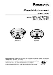
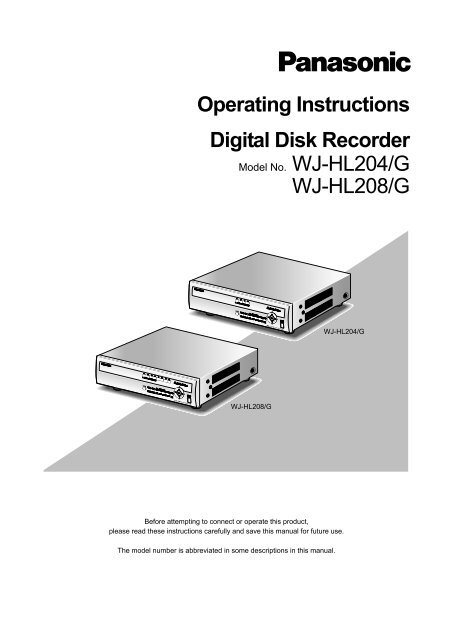
<strong>Operating</strong> <strong>Instructions</strong><br />
<strong>Digital</strong> <strong>Disk</strong> <strong>Recorder</strong><br />
Model No. <strong>WJ</strong>-HL204/G<br />
<strong>WJ</strong>-<strong>HL208</strong>/G<br />
<strong>WJ</strong>-<strong>HL208</strong>/G<br />
Before attempting to connect or operate this product,<br />
please read these instructions carefully and save this manual for future use.<br />
The model number is abbreviated in some descriptions in this manual.<br />
<strong>WJ</strong>-HL204/G
We declare under our sole responsibility that the product<br />
to which this declaration relates is in conformity with the<br />
standards or other normative documents following the<br />
provisions of Directives 2006/95/EC and 2004/108/EC.<br />
Wir erklären in alleiniger Verantwortung, daß das<br />
Produkt, auf das sich diese Erklärung bezieht, mit den<br />
folgenden Normen oder normativen Dokumenten<br />
übereinstimmt. Gemäß den Bestimmungen der<br />
Richtlinie 2006/95/EC und 2004/108/EC.<br />
Nous déclarons sous notre propre responsabilité que le<br />
produit auquel se réfère la présente déclaration est<br />
conforme aux normes spécifiées ou à tout autre<br />
document normatif conformément aux dispositions des<br />
directives 2006/95/CE et 2004/108/CE.<br />
Nosotros declaramos bajo nuestra única<br />
responsabilidad que el producto a que hace referencia<br />
esta declaración está conforme con las normas u otros<br />
documentos normativos siguiendo las estipulaciones de<br />
las directivas 2006/95/CE y 2004/108/CE.<br />
Noi dichiariamo sotto nostra esclusiva responsabilità<br />
che il prodotto a cui si riferisce la presente dichiarazione<br />
risulta conforme ai seguenti standard o altri documenti<br />
normativi conformi alle disposizioni delle direttive<br />
2006/95/CE e 2004/108/CE.<br />
CAUTION<br />
RISK OF ELECTRIC SHOCK<br />
DO NOT OPEN<br />
CAUTION: TO REDUCE THE RISK OF ELECTRIC SHOCK,<br />
DO NOT REMOVE COVER (OR BACK).<br />
NO USER-SERVICEABLE PARTS INSIDE.<br />
REFER SERVICING TO QUALIFIED SERVICE PERSONNEL.<br />
The lightning flash with arrowhead symbol,<br />
within an equilateral triangle, is intended to<br />
alert the user to the presence of uninsulated<br />
"dangerous voltage" within the product's<br />
enclosure that may be of sufficient magnitude<br />
to constitute a risk of electric shock<br />
to persons.<br />
The exclamation point within an equilateral<br />
triangle is intended to alert the user to the<br />
presence of important operating and maintenance<br />
(servicing) instructions in the literature<br />
accompanying the appliance.<br />
Power disconnection. Unit with or without ON-OFF<br />
switches have power supplied to the unit whenever the<br />
power cord is inserted into the power source; however,<br />
the unit is operational only when the ON-OFF switch is in<br />
the ON position. Unplug the power cord to disconnect<br />
the main power for all units.<br />
Wij verklaren als enige aansprakelijke, dat het product<br />
waarop deze verklaring betrekking heeft, voldoet aan de<br />
volgende normen of andere normatieve documenten,<br />
overeenkomstig de bepalingen van Richtlijnen<br />
2006/95/EC en 2004/108/EC.<br />
Vi erklærer os eneansvarlige for, at dette produkt, som<br />
denne deklaration omhandler, er i overensstemmelse<br />
med standarder eller andre normative dokumenter i<br />
følge bestemmelserne i direktivene 2006/95/EC og<br />
2004/108/EC.<br />
Vi deklarerar härmed vårt fulla ansvar för att den produkt<br />
till vilken denna deklaration hänvisar är i<br />
överensstämmelse med de standarder eller andra<br />
normativa dokument som framställs i direktiv nr<br />
2006/95/EC och 2004/108/EC.<br />
Ilmoitamme yksinomaisella vastuullamme, että tuote,<br />
jota tämä ilmoitus koskee, noudattaa seuraavia<br />
standardeja tai muita ohjeellisia asiakirjoja, jotka<br />
noudattavat direktiivien 2006/95/EC ja 2004/108/EC<br />
säädöksiä.<br />
Vi erklærer oss alene ansvarlige for at produktet som<br />
denne erklæringen gjelder for, er i overensstemmelse<br />
med følgende normer eller andre normgivende<br />
dokumenter som følger bestemmelsene i direktivene<br />
2006/95/EC og 2004/108/EC.<br />
WARNING:<br />
This is a class A product. In a domestic environment this<br />
product may cause radio interference in which case the<br />
user may be required to take adequate measures.<br />
WARNING:<br />
• This apparatus must be earthed.<br />
• Apparatus shall be connected to a main socket<br />
outlet with a protective earthing connection.<br />
• The mains plug or an appliance coupler shall<br />
remain readily operable.<br />
• To prevent fire or electric shock hazard, do not<br />
expose this apparatus to rain or moisture.<br />
• The apparatus should not be exposed to dripping or<br />
splashing and that no objects filled with liquids,<br />
such as vases, should be placed on the apparatus.<br />
• All work related to the installation of this product<br />
should be made by qualified service personnel or<br />
system installers.<br />
• The connections should comply with local electrical<br />
code.<br />
CAUTION:<br />
Before attempting to connect or operate this product,<br />
please read the label on the bottom.<br />
Apparaten skall anslutas till jordat uttag.<br />
1
2<br />
For U.K.<br />
FOR YOUR SAFETY PLEASE READ THE<br />
FOLLOWING TEXT CAREFULLY.<br />
This appliance is supplied with a moulded three pin<br />
mains plug for your safety and convenience.<br />
A 5 amp fuse is fitted in this plug.<br />
Should the fuse need to be replaced please ensure<br />
that the replacement fuse has a rating of 5 amp and<br />
that it is approved by ASTA or BSI to BS1362.<br />
Check for the ASTA mark or the BSI mark on<br />
the body of the fuse.<br />
If the plug contains a removable fuse cover you must<br />
ensure that it is refitted when the fuse is replaced.<br />
If you lose the fuse cover the plug must not be used<br />
until a replacement cover is obtained.<br />
A replacement fuse cover can be purchased from<br />
your local Panasonic Dealer.<br />
IF THE FITTED MOULDED PLUG IS UNSUITABLE<br />
FOR THE SOCKET OUTLET IN YOUR HOME<br />
THEN THE FUSE SHOULD BE REMOVED AND<br />
THE PLUG CUT OFF AND DISPOSED OF<br />
SAFELY.<br />
THERE IS A DANGER OF SEVERE ELECTRICAL<br />
SHOCK IF THE CUT OFF PLUG IS INSERTED<br />
INTO ANY 13 AMP SOCKET.<br />
If a new plug is to be fitted please observe the wiring<br />
code as shown below.<br />
If in any doubt please consult a qualified electrician.<br />
WARNING: This apparatus must be earthed.<br />
IMPORTANT<br />
The wires in this mains lead are coloured in<br />
accordance with the following code.<br />
Green-and-yellow: Earth<br />
Blue: Neutral<br />
Brown: Live<br />
As the colours of the wire in the mains lead of this<br />
appliance may not correspond with the coloured<br />
markings identifying the terminals in your plug,<br />
proceed as follows.<br />
The wire which is coloured green-and-yellow must<br />
be connected to the terminal in the plug which is<br />
marked with the letter E or by the earth symbol or<br />
coloured green or green-and-yellow.<br />
The wire which is coloured blue must be connected<br />
to the terminal in the plug which is marked with the<br />
letter N or coloured black.<br />
The wire which is coloured brown must be<br />
connected to the terminal in the plug which is marked<br />
with the letter L or coloured red.<br />
How to replace the fuse<br />
Open the fuse compartment with<br />
a screwdriver and replace the<br />
fuse and fuse cover.<br />
FUSE
Limitation of liability<br />
THIS PUBLICATION IS PROVIDED “AS IS” WITHOUT WARRANTY OF ANY KIND, EITHER EXPRESS OR IMPLIED,<br />
INCLUDING BUT NOT LIMITED TO, THE IMPLIED WARRANTIES OF MERCHANTABILITY, FITNESS FOR ANY<br />
PARTICULAR PURPOSE, OR NON-INFRINGEMENT OF THE THIRD PARTY’S RIGHT.<br />
THIS PUBLICATION COULD INCLUDE TECHNICAL INACCURACIES OR TYPOGRAPHICAL ERRORS.<br />
CHANGES ARE ADDED TO THE INFORMATION HEREIN, AT ANY TIME, FOR THE IMPROVEMENTS OF THIS<br />
PUBLICATION AND/OR THE CORRESPONDING PRODUCT(S).<br />
Disclaimer of warranty<br />
IN NO EVENT SHALL Panasonic System Networks Co., Ltd. BE LIABLE TO ANY PARTY OR ANY PERSON, EXCEPT FOR<br />
REPLACEMENT OR REASONABLE MAINTENANCE OF THE PRODUCT, FOR THE CASES, INCLUDING BUT NOT LIMITED TO<br />
BELOW:<br />
(1) ANY DAMAGE AND LOSS, INCLUDING WITHOUT LIMITATION, DIRECT OR INDIRECT, SPECIAL, CONSEQUENTIAL OR<br />
EXEMPLARY, ARISING OUT OF OR RELATING TO THE PRODUCT;<br />
(2) PERSONAL INJURY OR ANY DAMAGE CAUSED BY INAPPROPRIATE USE OR NEGLIGENT OPERATION OF THE USER;<br />
(3) UNAUTHORIZED DISASSEMBLE, REPAIR OR MODIFICATION OF THE PRODUCT BY THE USER;<br />
(4) INCONVENIENCE OR ANY LOSS ARISING WHEN IMAGES ARE NOT DISPLAYED, DUE TO ANY REASON OR CAUSE<br />
INCLUDING ANY FAILURE OR PROBLEM OF THE PRODUCT;<br />
(5) ANY PROBLEM, CONSEQUENTIAL INCONVENIENCE, OR LOSS OR DAMAGE, ARISING OUT OF THE SYSTEM<br />
COMBINED BY THE DEVICES OF THIRD PARTY;<br />
(6) ANY CLAIM OR ACTION FOR DAMAGES, BROUGHT BY ANY PERSON OR ORGANIZATION BEING A PHOTOGENIC<br />
SUBJECT, DUE TO VIOLATION OF PRIVACY WITH THE RESULT OF THAT SURVEILLANCECAMERA'S PICTURE,<br />
INCLUDING SAVED DATA, FOR SOME REASON, BECOMES PUBLIC OR IS USED FOR THE PURPOSE OTHER THAN<br />
SURVEILLANCE;<br />
(7) LOSS OF REGISTERED DATA CAUSED BY ANY FAILURE;<br />
(8) ANY PROBLEM, CONSEQUENTIAL INCONVENIENCE, ANY LOSS OR DAMAGE, ARISING OUT OF THE<br />
IMPROPER DETECTION OR SLIP-UP IN DETECTION BY MOTION DETECTION AND MOTION SEARCH<br />
FUNCTIONS OF THE PRODUCT.<br />
Trademarks and registered trademarks<br />
Adobe, Adobe logo and Reader are either registered trademarks or trademarks of Adobe Systems Incorporated in the United States<br />
and/or other countries.<br />
Microsoft, Windows, Windows Vista, Internet Explorer, and DirectX are either registered trademarks or trademarks of Microsoft<br />
Corporation in the United States and other countries.<br />
Intel and Intel Core are trademarks or registered trademarks of Intel Corporation or its subsidiaries in the United States and other<br />
countries.<br />
Other names of companies and products contained in these operating instructions may be trademarks or registered trademarks of their<br />
respective owners.<br />
Network security<br />
As you will use this product connected to a network, your attention is called to the following security risks.<br />
(1) Leakage or theft of information through this product<br />
(2) Use of this product for illegal operations by persons with malicious intent<br />
(3) Interference with or stoppage of this product by persons with malicious intent<br />
It is your responsibility to take precautions such as those described below to protect yourself against the above network security risks.<br />
• Use this product in a secured network not connected to the Internet.<br />
• If this product is connected to a network that includes PCs, make sure that the system is not infected by computer viruses or other<br />
malicious entities (using a regularly updated anti-virus program, anti-spyware program, etc.).<br />
• Protect your network against unauthorized access by restricting users to those who log in with an authorized user name and password.<br />
• Apply measures such as user authentication for the servers and the connected devices to protect your network against leakage or theft<br />
of information, including image data, authentication information (user names and passwords), alarm mail information, FTP server<br />
information, etc.<br />
3
4<br />
Important safety instructions<br />
(1) Read these instructions.<br />
(2) Keep these instructions.<br />
(3) Heed all warnings.<br />
(4) Follow all instructions.<br />
(5) Do not use this apparatus near water.<br />
(6) Clean only with dry cloth.<br />
(7) Do not block any ventilation openings. Install in accordance with the manufacturer's instructions.<br />
(8) Do not install near any heat sources such as radiators, heat registers, stoves, or other apparatus (including amplifiers) that produce<br />
heat.<br />
(9) Do not defeat the safety purpose of the polarized or grounding-type plug. A polarized plug has two blades with one wider than the<br />
other. A grounding type plug has two blades and a third grounding prong. The wide blade or the third prong are provided for your<br />
safety. If the provided plug does not fit into your outlet, consult an electrician for replacement of the obsolete outlet.<br />
(10) Protect the power cord from being walked on or pinched particularly at plugs, convenience receptacles, and the point where they<br />
exit from the apparatus.<br />
(11) Only use attachments/accessories specified by the manufacturer.<br />
(12) Use only with the cart, stand, tripod, bracket, or table specified by the manufacturer, or sold with the apparatus. When a cart is<br />
used, use caution when moving the cart/apparatus combination to avoid injury from tip-over.<br />
(13) Unplug this apparatus during lightning storms or when unused for long periods of time.<br />
S3125A<br />
(14) Refer all servicing to qualified service personnel. Servicing is required when the apparatus has been damaged in any way, such as<br />
power-supply cord or plug is damaged, liquid has been spilled or objects have fallen into the apparatus, the apparatus has been<br />
exposed to rain or moisture, does not operate normally, or has been dropped.
Precautions<br />
Power source<br />
The input power source for this product is 100 V AC to 240 V AC, 50 Hz/60 Hz. Do not connect to the outlet<br />
that provides the power to equipments that requires a measurable amount of power (such as a copy machine,<br />
air conditioner, etc.). Avoid placing this product in locations where is subject to water.<br />
Ambient operating temperature<br />
Use this product at temperatures between +5 °C to +40 °C. Failure to do so may damage the internal parts or<br />
cause malfunction. Performance and lifetime of hard disk drives are easily affected by heat (used at high<br />
temperature). It is recommended to use this product at temperatures between +20 °C to +30 °C.<br />
Power cable<br />
Connect the power cable firmly. Align the connected power cable not to be pulled/stressed. To cut the power<br />
supply, unplug the power plug of this product from the AC outlet. When using the power supply control unit,<br />
turn off the power of the power supply control unit.<br />
Built-in backup battery<br />
• Built-in backup battery is consumed when the power supply is shut down from the AC outlet. In this case, internal<br />
clock may keep bad time or the operative condition may be different to that before the electric power failure.<br />
• The built-in battery life is approximately 5 years as an indication of replacement. (The built-in battery life may<br />
become shorter depending on the use condition.)Replace the built-in battery after 5 years of use. (“5 years of use”<br />
is just an indication of replacement. We are not providing any guarantee of the built-in battery lifetime.)When the<br />
built-in battery life runs out, some settings such as the time and date setting will not be saved once the power is<br />
turned off.<br />
• Ask your dealer when replacement of the battery is required.<br />
Hard disk drive (HDD)<br />
• Hard disk drives are vulnerable to vibration. Handle them with care. It is possible to damage them if they are moved<br />
while their motors are still running.<br />
• Do not move them just after turning the power off (for around 30 seconds).<br />
• The lifetime of hard disk drives is limited by use. Write errors may occur frequently after around 20 000 hours of<br />
operation, and the head and motor deterioration may occur after around 30 000 hours of operation. They will reach<br />
the end of their lifetime after 30 000 hours of operation if they have been used at the recommended ambient<br />
temperature (approx. +25 °C).<br />
• It is recommended to replace them after around 18 000 hours of operation to prevent data loss from disk failures.<br />
• When hard disk drive trouble occurs, replace it immediately.<br />
Contact your dealer about servicing.<br />
Prevent condensation from forming<br />
If this happens, it can cause malfunction.<br />
Leave it switched off for around 2 hours in the following cases.<br />
• When this product is placed in an extremely humid place.<br />
• When this product is placed in a room where a heater has just been turned on.<br />
• When this product is moved from an air-conditioned room to a humid and high-temperature room.<br />
When this product is not supposed to be used for a certain period<br />
Turn on the power (approximately once a week), and perform recording/playback to prevent interferences<br />
with functions.<br />
Cleaning<br />
• Turn the power off, and then use a soft cloth to clean this product. When the dirt is hard to remove, use a mild<br />
detergent and wipe gently. Wipe out the detergent completely using a soft cloth.<br />
• Do not use strong or abrasive detergents when cleaning the body.<br />
• When using a chemical cloth for cleaning, read the caution provided with the chemical cloth product..<br />
5
6<br />
AVC patent portfolio license<br />
This product is licensed under the AVC Patent Portfolio License for the personal and non-commercial use of<br />
a consumer to (i) Encode video in compliance with the AVC Standard (“AVC video”) and/or (ii) Decode AVC<br />
video that was encoded by a consumer engaged in a personal and non-commercial activity and/or was<br />
obtained from a video provider licensed to provide AVC video. No license is granted or shall be implied for<br />
any other use. Additional information may be obtained from MPEG LA, L.L.C.<br />
See http://www.mpegla.com<br />
GPL/LGPL<br />
• This product contains software licensed under GPL (GNU General Public License), LGPL (GNU Lesser General<br />
Public License), etc.<br />
• Customers can duplicate, distribute and modify the source code of the software under license of GPL and/or LGPL.<br />
• Read the “readme.txt” the provided CD-ROM for further information about the software.<br />
• Please note that Panasonic shall not respond to any inquiries regarding the source code.<br />
Handle this product with care.<br />
Do not strike or shake, as this may damage this product.<br />
Do not strike or give a strong shock to this product.<br />
It may cause damage or allow water to enter this product.<br />
Precautions for installation<br />
This product is designed for indoor use.<br />
Avoid the following locations for installation.<br />
• Locations exposed to direct sunlight<br />
• Places subject to having strong vibration or impact<br />
• Near magnetic field sources such as a television or speakers<br />
• Place where condensation forms easily, where temperature changes greatly, humid places<br />
• Steamy and oily places such as kitchens<br />
• Places which are not level<br />
• Places subject to dust<br />
• Places subject to water splash or spray<br />
Do not install this product in locations where the product or the cables can be destroyed or damaged by<br />
persons with malicious intent.<br />
Place this product horizontally on a level surface.<br />
Do not place this product in an upright position. When stacking multiple recorders,<br />
clear a space of more than 5 cm from both sides, the top, the bottom and the rear<br />
of them.<br />
Heat dissipation<br />
Refer to the following to prevent fire and malfunction of this<br />
product.<br />
• Do not bock the ventilation openings in the cover to prevent<br />
this product from overheating. Maintain this product<br />
periodically to prevent dust from blocking openings.<br />
• A lifetime of cooling fans is limited by use. It is recommended<br />
to replace them after approx. 30 000 hours of operation.<br />
Contact your dealer for replacement of the cooling fans.<br />
• Clear a space of more than 5 cm from both sides, the top and<br />
the rear of this product.<br />
More than<br />
5 cm<br />
More than<br />
5 cm<br />
More than<br />
5 cm
Avoid placing the unit near noise sources<br />
If the cables are placed near noise sources such as fluorescent lamps, noises may be produced. In this case,<br />
rewire avoiding the noise sources, or move this product to a place far from the source.<br />
Power source<br />
A grounding connection must be made before connecting the power plug of this product to the main power<br />
supply. When disconnecting the grounding wire, make sure that the power plug of this product is<br />
disconnected from the main power supply.<br />
How to mount the power cord<br />
Insert the power cord to the limit on the recorder.<br />
Be sure to connect the power cord via any of the following breaking devices:<br />
• Connect the power cord via a power supply control unit.<br />
• Install the product near a power outlet, and connect the power cord via the power plug.<br />
• Connect the power cord to the breaker with contact gap of 3.0 mm or more of a distribution board. The breaker<br />
shall be able to shut down all the poles of the main power supply except the ground protective conductor.<br />
For BNC cable connection<br />
Use only the recommended plug below when connecting the BNC<br />
plug to the connectors on the rear panel of the recorder.<br />
Applicable plug: BS CECC2212: 1981<br />
* Suffixes attached to the standards may be updated.<br />
Tip dimensions inside the recommended BNC plug<br />
Important:<br />
• A compatible plug shall be used. Failure to observe this may cause trouble such<br />
as poor contact. At worst, the connector of this product may be damaged.<br />
Avoid placing receptacles that contain liquids such as water near this product.<br />
If liquid spills onto this product, it may cause fire or an electric shock.<br />
Plug<br />
BNC cable (locally procured)<br />
ø1.32 mm - ø1.37 mm<br />
ø0.13 mm -ø0.69 mm<br />
7
8<br />
Table of Contents<br />
Chapter 1 -- Introduction ..............................................................................................................................12<br />
Features......................................................................................................................................................12<br />
Technical Overview...................................................................................................................................12<br />
Chapter 2 -- Installation ................................................................................................................................14<br />
Package Contents .....................................................................................................................................14<br />
Required Installation Tools ......................................................................................................................15<br />
Video Input Connector [VIDEO IN 1 to 8 or 4].....................................................................................15<br />
Video Output Connector [VIDEO OUT 1 to 8 or 4]..............................................................................15<br />
RS485 Terminal [485 A / B] ................................................................................................................16<br />
Alarm Input / Output Terminal [ALARM IN] / [ALARM OUT]..............................................................16<br />
Network Port [10/100BASE-T] ............................................................................................................16<br />
Serial Port [SERIAL]............................................................................................................................16<br />
Audio Input / Output Connector [AUDIO IN 1 to 4] / [AUDIO OUT] (RCA pin jack)............................16<br />
Monitor Output Connector [MON 1] / [MON 2 (SPOT)] / [MON 3 (VGA)] ..........................................17<br />
Factory Reset Switch ...........................................................................................................................17<br />
Power Inlet [AC IN]..............................................................................................................................17<br />
Chapter 3 -- Configuration ...........................................................................................................................18<br />
Front Panel Controls.................................................................................................................................18<br />
Camera Buttons [1] to [8] or [4]...........................................................................................................18<br />
HDD Indicator [HDD]...........................................................................................................................19<br />
Alarm Indicator [ALARM] ....................................................................................................................19<br />
Link Indicator [LINK]............................................................................................................................19<br />
Copy Indicator [COPY]........................................................................................................................19<br />
Operate Indicator [OPERATE]............................................................................................................19<br />
Mouse / Copy Port [MOUSE/COPY] ..................................................................................................19<br />
Arrow Buttons [ ] / [ ] / [ ] / [ ] ...................................................................................................19<br />
Play / Pause Button [ ]......................................................................................................................19<br />
Menu / PTZ Button ([MENU] or [PTZ]) ...............................................................................................19<br />
Playback / Edit Group Button ([PLAYBACK] or [EDIT GROUP]).......................................................20<br />
Next Group / Sequence Button ([NEXT GROUP] or [SEQ])..............................................................20<br />
Multiscreen / Spot Button ([MULTISCREEN] or [SPOT])...................................................................20<br />
EL-Zoom / Return Button ([EL-ZOOM] or [RET]) ...............................................................................20<br />
Copy / Preset View Button ([COPY] or [PRESET VIEW])..................................................................20<br />
Alarm / Preset Set Button ([ALARM] or [PRESET SET]) ...................................................................20<br />
Panic Button [PANIC]..........................................................................................................................20<br />
Turning on the Power ...............................................................................................................................21<br />
Initial Unit Setup ........................................................................................................................................21<br />
Setup Screen..............................................................................................................................................22<br />
System Setup.............................................................................................................................................22<br />
Information ...............................................................................................................................................23<br />
Date/Time ................................................................................................................................................25<br />
Storage.....................................................................................................................................................26<br />
User..........................................................................................................................................................27<br />
Shutdown .................................................................................................................................................29<br />
Network Setup ...........................................................................................................................................29<br />
Network....................................................................................................................................................29<br />
Mail...........................................................................................................................................................31<br />
Devices Setup ............................................................................................................................................32<br />
Camera ....................................................................................................................................................32<br />
Audio ........................................................................................................................................................33<br />
Alarm-Out.................................................................................................................................................34<br />
Display .....................................................................................................................................................35<br />
Recording Setup........................................................................................................................................37<br />
Record......................................................................................................................................................37
Schedule ..................................................................................................................................................39<br />
Pre-Event .................................................................................................................................................40<br />
Event Setup................................................................................................................................................41<br />
Alarm-In....................................................................................................................................................41<br />
Motion Detection......................................................................................................................................43<br />
Video Loss ...............................................................................................................................................45<br />
Video Blind...............................................................................................................................................46<br />
System Event...........................................................................................................................................48<br />
Event Status.............................................................................................................................................49<br />
Chapter 4 -- Operation ..................................................................................................................................50<br />
Turning on the Power ...............................................................................................................................50<br />
Live Monitoring..........................................................................................................................................50<br />
Live Monitoring Menu ..............................................................................................................................51<br />
Edit Group Mode......................................................................................................................................52<br />
EL-Zoom Mode ........................................................................................................................................52<br />
PTZ Mode ................................................................................................................................................52<br />
Event Monitoring......................................................................................................................................54<br />
Covert Camera.........................................................................................................................................54<br />
Spot Monitoring........................................................................................................................................54<br />
Using a Mouse ...........................................................................................................................................55<br />
Recording Video........................................................................................................................................56<br />
Panic Recording.......................................................................................................................................56<br />
Recording Audio........................................................................................................................................56<br />
Playing Recorded Video ...........................................................................................................................56<br />
Searching Video ........................................................................................................................................58<br />
Search Menu............................................................................................................................................58<br />
Event Log Search ....................................................................................................................................60<br />
Record Table Search...............................................................................................................................61<br />
Calendar Search......................................................................................................................................62<br />
Motion Search..........................................................................................................................................62<br />
Clip Copy..................................................................................................................................................63<br />
Appendix ........................................................................................................................................................66<br />
Display Setup Menu of Camera ...............................................................................................................66<br />
System requirements for a PC.................................................................................................................66<br />
Clip Player ..................................................................................................................................................67<br />
Web Browser..............................................................................................................................................69<br />
Watch Mode ...............................................................................................................................................70<br />
Search Mode ..............................................................................................................................................72<br />
Time Overlap..............................................................................................................................................74<br />
Pin Outs ......................................................................................................................................................75<br />
Alarm Input / Output.................................................................................................................................75<br />
RS485 ......................................................................................................................................................75<br />
Map of Screens ..........................................................................................................................................76<br />
Recording Duration (for reference purpose only) .................................................................................77<br />
System Log Notices ..................................................................................................................................78<br />
Error Code Notices....................................................................................................................................79<br />
Troubleshooting ........................................................................................................................................80<br />
Specifications ............................................................................................................................................82<br />
9
10<br />
List of Illustrations<br />
Figure 1 : Typical installation...........................................................................................................................13<br />
Figure 2 : 8-channel model rear panel............................................................................................................15<br />
Figure 3 : 4-channel model rear panel............................................................................................................15<br />
Figure 4 : 8-channel model front panel ...........................................................................................................18<br />
Figure 5 : 4-channel model front panel ...........................................................................................................18<br />
Figure 6 : Login screen ...................................................................................................................................21<br />
Figure 7 : Logout screen .................................................................................................................................21<br />
Figure 8 : Setup screen...................................................................................................................................22<br />
Figure 9 : Virtual Keyboard screen .................................................................................................................22<br />
Figure 10 : System menu................................................................................................................................22<br />
Figure 11 : Information screen ........................................................................................................................23<br />
Figure 12 : Upgrade screen ............................................................................................................................23<br />
Figure 13 : Setup Import screen .....................................................................................................................23<br />
Figure 14 : Setup Export screen .....................................................................................................................24<br />
Figure 15 : System Log screen.......................................................................................................................24<br />
Figure 16 : System Log Export screen ...........................................................................................................24<br />
Figure 17 : Date/Time - Date/Time screen .....................................................................................................25<br />
Figure 18 : Date/Time - Holiday screen ..........................................................................................................25<br />
Figure 19 : Date/Time - Time Sync. screen....................................................................................................26<br />
Figure 20 : Storage - Information screen ........................................................................................................26<br />
Figure 21 : Internal 1(Storage Format) screen ...............................................................................................26<br />
Figure 22 : Internal 1 (Storage Information) screen........................................................................................27<br />
Figure 23 : Storage - Status screen................................................................................................................27<br />
Figure 24 : User screen...................................................................................................................................27<br />
Figure 25 : New Group screen........................................................................................................................28<br />
Figure 26 : New User (User Information) screen............................................................................................28<br />
Figure 27 : Shutdown screen ..........................................................................................................................29<br />
Figure 28 : Network menu...............................................................................................................................29<br />
Figure 29 : Network - Network screen ............................................................................................................29<br />
Figure 30 : Network - LAN (Manual) screen ...................................................................................................30<br />
Figure 31 : Port Number Setup screen...........................................................................................................30<br />
Figure 32 : Network - LAN (DHCP) screen.....................................................................................................31<br />
Figure 33 : Network - Web Browser screen....................................................................................................31<br />
Figure 34 : Mail screen....................................................................................................................................31<br />
Figure 35 : Authentication screen ...................................................................................................................32<br />
Figure 36 : Devices menu ...............................................................................................................................32<br />
Figure 37 : Camera - Settings screen.............................................................................................................32<br />
Figure 38 : Camera - PTZ screen ...................................................................................................................33<br />
Figure 39 : PTZ device list ..............................................................................................................................33<br />
Figure 40 : Port Setup screen .........................................................................................................................33<br />
Figure 41 : Audio screen .................................................................................................................................33<br />
Figure 42 : Alarm-Out - Settings screen .........................................................................................................34<br />
Figure 43 : Alarm-Out - Schedule screen .......................................................................................................34<br />
Figure 44 : Display - OSD screen ...................................................................................................................35<br />
Figure 45 : OSD Margin screen ......................................................................................................................35<br />
Figure 46 : Display - Main Monitor screen......................................................................................................35<br />
Figure 47 : Display - Spot Monitor screen ......................................................................................................36<br />
Figure 48 : Display - VGA screen ...................................................................................................................36<br />
Figure 49 : VGA monitor position screen........................................................................................................37<br />
Figure 50 : Record menu ................................................................................................................................37<br />
Figure 51 : Record - Settings screen ..............................................................................................................37<br />
Figure 52 : Record - Panic Record screen .....................................................................................................38<br />
Figure 53 : Schedule screen ...........................................................................................................................39<br />
Figure 54 : Schedule - Settings (Advanced Mode) setup screen...................................................................40<br />
Figure 55 : Default (Schedule - Advanced Mode) screen ..............................................................................40<br />
Figure 56 : Pre-Event screen ..........................................................................................................................41
Figure 57 : Event menu..................................................................................................................................41<br />
Figure 58 : Alarm-In - Settings screen ............................................................................................................41<br />
Figure 59 : Alarm-In - Actions 1 screen ..........................................................................................................42<br />
Figure 60 : Alarm-In Notify screen ..................................................................................................................42<br />
Figure 61 : Alarm-In - Actions 2 screen ..........................................................................................................42<br />
Figure 62 : Motion Detection - Settings screen ..............................................................................................43<br />
Figure 63 : Motion Detection Sensitivity screen .............................................................................................43<br />
Figure 64 : Motion Detection Min. Blocks screen ...........................................................................................43<br />
Figure 65 : Motion Detection Zone screen......................................................................................................43<br />
Figure 66 : Motion Detection Zone menu .......................................................................................................44<br />
Figure 67 : Daytime Setup screen ..................................................................................................................44<br />
Figure 68 : Motion Detection - Actions 1 screen.............................................................................................44<br />
Figure 69 : Motion Detection - Actions 2 screen.............................................................................................45<br />
Figure 70 : Video Loss - Settings screen........................................................................................................45<br />
Figure 71 : Video Loss - Actions 1 screen......................................................................................................45<br />
Figure 72 : Video Loss - Actions 2 screen......................................................................................................46<br />
Figure 73 : Video Blind - Settings screen .......................................................................................................46<br />
Figure 74 : Video Blind - Sensitivity screen ....................................................................................................46<br />
Figure 75 : Video Blind - Actions 1 screen......................................................................................................47<br />
Figure 76 : Video Blind - Actions 2 screen......................................................................................................47<br />
Figure 77 : System Event - Health Check screen...........................................................................................48<br />
Figure 78 : Check Recording screen ..............................................................................................................48<br />
Figure 79 : System Event - Storage screen....................................................................................................48<br />
Figure 80 : System Event - Actions screen.....................................................................................................49<br />
Figure 81 : Event Status - Event Status screen..............................................................................................49<br />
Figure 82 : Live Monitoring menu ...................................................................................................................50<br />
Figure 83 : Sequence pattern .........................................................................................................................51<br />
Figure 84 : Camera menu ...............................................................................................................................51<br />
Figure 85 : PTZ Select Camera menu............................................................................................................53<br />
Figure 86 : PTZ Preset menu..........................................................................................................................53<br />
Figure 87 : Advanced PTZ menu....................................................................................................................53<br />
Figure 88 : PTZ panel .....................................................................................................................................53<br />
Figure 89 : Spot Monitor menu .......................................................................................................................54<br />
Figure 90 : Mouse Display menu ....................................................................................................................55<br />
Figure 91 : Select Playback Camera menu ....................................................................................................56<br />
Figure 92 : Compact View Record Table........................................................................................................57<br />
Figure 93 : Search menu.................................................................................................................................58<br />
Figure 94 : Search menu.................................................................................................................................58<br />
Figure 95 : Go to menu ...................................................................................................................................58<br />
Figure 96 : Go to the Date/Time screen .........................................................................................................58<br />
Figure 97 : Export menu..................................................................................................................................59<br />
Figure 98 : Camera menu ...............................................................................................................................59<br />
Figure 99 : Event Log Search screen .............................................................................................................60<br />
Figure 100 : Event Log Search Option screen ...............................................................................................60<br />
Figure 101 : Record Table Search screen......................................................................................................61<br />
Figure 102 : Search menu ..............................................................................................................................61<br />
Figure 103 : Calendar Search screen.............................................................................................................62<br />
Figure 104 : Motion Search screen.................................................................................................................62<br />
Figure 105 : Motion Search Option screen.....................................................................................................63<br />
Figure 106 : Clip Copy screen ........................................................................................................................64<br />
11
12<br />
Chapter 1 -- Introduction<br />
Features<br />
Your color digital disk recorder provides recording capabilities for eight camera inputs. It provides<br />
exceptional picture quality in both live and playback modes, and offers the following features:<br />
� 8 or 4 composite video inputs<br />
<strong>WJ</strong>-<strong>HL208</strong> is 8-channel model<br />
<strong>WJ</strong>-HL204 is 4-channel model<br />
� H.264 codec for efficient digital video recording<br />
� Real time recording<br />
200 ips with standard (CIF) resolution (8-channel model)<br />
100 ips with standard (CIF) resolution (4-channel model)<br />
� Selectable 4 recording qualities (Very High, High, Standard, Basic)<br />
� Selectable 3 recording resolutions (D1, Half-D1, CIF)<br />
� Multiple Recording mode (Time-Laps, Pre-Event, Alarm, Motion and Panic)<br />
� Multiple Search engine (Date/Time, Calendar, Record table, Event and Motion)<br />
� Easy operation with user-friendly GUI (Graphical User Interface) and mouse<br />
� 4-channel audio recording and 1-channel audio playback<br />
� Camera control via RS-485 (Panasonic and Pelco-D protocol supported)<br />
� Continues recording while transmitting to web browser and during playback<br />
� Self-diagnostics with automatic notification including HDD S.M.A.R.T. protocol<br />
� Equipped with 3 HDD slots<br />
Technical Overview<br />
In addition to replacing both a time-lapse VCR and a multiplexer in a security installation, your recorder has<br />
many features that make it much more powerful and easier to use than even the most advanced VCR.<br />
The recorder converts analog PAL video to digital images and records them on a hard disk drive. Using a<br />
hard disk drive allows you to access recorded video almost instantaneously; there is no need to rewind tape.<br />
The technology also allows you to view recorded video while the recorder continues recording video.<br />
<strong>Digital</strong>ly recorded video has several advantages over analog video recorded on tape. There is no need to<br />
adjust tracking. You can freeze frames, fast forward, fast reverse, slow forward and slow reverse without<br />
image streaking or tearing. <strong>Digital</strong> video can be indexed by time or events, and you can instantly view video<br />
after selecting the time or event.<br />
Your recorder can be set up for event or time-lapse recording. You can define times to record, and the<br />
schedule can change for different days of the week and user defined holidays.
The recorder can be set up to alert you when the hard disk drive is full, or it can be set to record over the<br />
oldest video once the disk is full.<br />
You can view video and control your recorder remotely by connecting via Ethernet. There is a COPY ports<br />
that can be used to upgrade the system or copy video clips to external flash drives.<br />
Note: This manual covers the 8- and 4-channel digital disk recorders. The recorders are almost<br />
the same specification except for the number of cameras and alarms that can be<br />
connected and the number of cameras that can be displayed. In the 4-channel model, a<br />
part of function is not equipped.<br />
For simplicity, the illustrations and descriptions in this manual refer to the 8-channel<br />
model.<br />
Figure 1 : Typical installation<br />
13
14<br />
Chapter 2 -- Installation<br />
Package Contents<br />
The package contains the following:<br />
� <strong>Digital</strong> <strong>Disk</strong> <strong>Recorder</strong><br />
� Power Cord ×2<br />
� <strong>Operating</strong> <strong>Instructions</strong> (This Document)<br />
� Assembly Screws for Adding Hard <strong>Disk</strong> Drives<br />
Serial ATA cable ×2<br />
HDD Fixing Screw ×12 (including 4 as spares)<br />
� CD-ROM ×1<br />
The CD-ROM contains the regulations documents and important safety instructions (PDFs) written<br />
in the following language; French, German, Spanish, Italian and Russian.<br />
Adobe ® Reader ® is required to read the PDF files on the provided CD-ROM. When Adobe ®<br />
Reader ® is not installed on the PC, download the latest Adobe ® Reader ® from the Adobe web site<br />
and install it.
Required Installation Tools<br />
No special tools are required to install the recorder. Refer to the installation manuals for the other items that<br />
make up part of your system.<br />
Figure 2 : 8-channel model rear panel<br />
Figure 3 : 4-channel model rear panel<br />
Video Input Connector Video Output Connector RS485 Terminal<br />
Alarm Input / Output Terminal Network Port Serial Port<br />
Audio Input / Output Connector Monitor Output Connector Factory Reset Switch<br />
Power Inlet<br />
Your recorder can be used with PAL equipment.<br />
Video Input Connector [VIDEO IN 1 to 8 or 4]<br />
Connect the coaxial cables from the video sources to the Video Input BNC connectors.<br />
The 4-channel model has 4 Video Input BNC connectors [VIDEO IN 1 to 4].<br />
Video Output Connector [VIDEO OUT 1 to 8 or 4]<br />
If you would like to connect your video source to another device, you can use the Video Output BNC<br />
connectors.<br />
The 4-channel model has 4 Video Output BNC connectors [VIDEO Out 1 to 4].<br />
Note: The Video Output BNC connectors are auto terminated. Do NOT connect a cable to the<br />
Video Output BNC connectors unless it is connected to a terminated device because it will<br />
cause poor quality video.<br />
15
16<br />
RS485 Terminal [485 A / B]<br />
The recorder can control PTZ (Pan/Tilt/Zoom) cameras using RS485 half-duplex serial communications<br />
signals. Connect RX+/TX+ and RX-/ TX- of the control system to the A and B (respectively) of the recorder.<br />
See “Chapter 3 -- Configuration” and the PTZ camera’s manual for configuring the RS485 connection.<br />
Alarm Input / Output Terminal [ALARM IN] / [ALARM OUT]<br />
Note: To make connections on the Alarm Terminal Strip, press and hold the button and insert the<br />
wire in the hole below the button. After releasing the button, tug gently on the wire to<br />
make certain it is connected. To disconnect a wire, press and hold the button above the<br />
wire and pull out the wire.<br />
The 4-Channel model has 4 Alarm Input Terminals [AI1] to [AI4].<br />
[AI1] to [AI8] or [AI4] (Alarm Input) : You can use external devices to signal the recorder to react to events.<br />
Mechanical or electrical switches can be wired to the [AI] (Alarm Input) and [GND] (Ground) terminals. The<br />
threshold voltage of electrical switches for [NC] (Normally Closed) is above 2.4 V and for [NO] (Normally<br />
Open) is below 0.3 V, and should be stable at least 0.5 seconds to be detected. The voltage range of alarm<br />
input is from 0 V to 5 V. See “Chapter 3 -- Configuration” for configuring alarm input.<br />
[GND] (Ground) : Connect the ground side of the Alarm input and/or alarm output to the GND terminal.<br />
Note: All the terminals marked GND are common.<br />
[NC]/[NO] (Relay Alarm Outputs) : The recorder can activate external devices such as buzzers or lights.<br />
Connect the device to the [COM] (Common) and [NC] (Normally Closed) or [COM] and [NO] (Normally<br />
Open) terminals. [NC]/[NO] is a relay output which sinks 1 A 30 Vpeak (maximum). See “Chapter 3 --<br />
Configuration” for configuring alarm output.<br />
[ARI] (Alarm Reset In) : An external signal to the Alarm Reset In can be used to reset both the Alarm Out<br />
signal and the recorder’s internal buzzer. Mechanical or electrical switches can be wired to the [ARI] (Alarm<br />
Reset In) and [GND] (Ground) terminals. The threshold voltage is below 0.3 V and should be stable at least<br />
0.5 seconds to be detected. Connect the wires to the [ARI] (Alarm Reset In) and [GND] (Ground) terminals.<br />
Network Port [10/100BASE-T]<br />
The recorder can be networked using the 10/100Mbps Ethernet connector. Connect a Cat5 cable with an<br />
RJ-45 jack to the recorder connector. The recorder can be networked with a computer for remote monitoring,<br />
searching. See “Chapter 3 -- Configuration” for configuring the Ethernet connections.<br />
Important: The network port is not designed to be connected directly with cable or wire<br />
intended for outdoor use.<br />
Please keep away a cat5 cable and other cable which has a lot of noises,<br />
lightning and surge.<br />
Serial Port [SERIAL]<br />
Reserved.<br />
Audio Input / Output Connector [AUDIO IN 1 to 4] / [AUDIO OUT] (RCA pin jack)<br />
Your recorder can record audio from up to four sources. Connect the audio sources to the Audio Input<br />
Connectors 1 to 4 as needed using RCA jacks.<br />
Connect the Audio Output Connector to your amplifier.<br />
Note: It is the user’s responsibility to determine if local laws and regulations permit recording<br />
audio.<br />
The recorder does not have amplified audio output, so you will need a speaker with an<br />
amplifier. The recorder does not have a pre-amplifier for audio input, so the audio input<br />
should be from an amplified source, not directly from a microphone.
Monitor Output Connector [MON 1] / [MON 2 (SPOT)] / [MON 3 (VGA)]<br />
A [MON 3 (VGA)] connector is provided so that you can use a standard, multi-sync computer monitor as your<br />
main monitor. Use the cable supplied with your monitor to connect it to the recorder.<br />
Connect the main monitor to the [MON 1] connector. Connect the spot monitor to the [MON 2 (SPOT)]<br />
connector as needed.<br />
Note: The [MON 3 (VGA)] and [MON 1] (BNC) connectors may be connected to individual<br />
monitors for simultaneous operation.<br />
Please keep away cables and other cables which have a lot of noises, lightning and surge.<br />
Factory Reset Switch<br />
The recorder has a Factory Reset switch to the left of the [MON 3 (VGA)] connector (4-channel model : the<br />
right of the Serial Port) on the rear panel. This switch will only be used on the rare occasions that you want to<br />
return all the settings to the original factory settings.<br />
Important: When using the Factory Reset Switch, you will lose any settings you have<br />
saved. (Excluded camera titles you can change in the Web Browser.)<br />
To reset the unit, you will need a straightened paperclip:<br />
1. Turn the recorder off.<br />
2. Turn it on again with insert the straightened paperclip into the unlabeled hole in the left of the [MON 3<br />
(VGA)] connector (or the right of the Serial Port : 4-channel model).<br />
Note: Continue inserting until the internal buzzer starts to sound. (approximately 30 seconds<br />
after turned on)<br />
3. Release the reset switch. All of the recorder’s settings are now at the original settings it had when it<br />
left the factory.<br />
Power Inlet [AC IN]<br />
Connect the provided AC power cord to the recorder and then to a wall outlet.<br />
WARNING: ROUTE POWER CORDS SO THAT THEY ARE NOT A TRIPPING HAZARD.<br />
MAKE CERTAIN THE POWER CORD WILL NOT BE PINCHED OR ABRADED<br />
BY FURNITURE. DO NOT INSTALL POWER CORDS UNDER RUGS OR<br />
CARPET.<br />
THE POWER CORD HAS A GROUNDING PIN. IF YOUR POWER OUTLET<br />
DOES NOT HAVE A GROUNDING PIN RECEPTACLE, DO NOT MODIFY THE<br />
PLUG. DO NOT OVERLOAD THE CIRCUIT BY PLUGGING TOO MANY<br />
DEVICES IN TO ONE CIRCUIT.<br />
Your recorder is now ready to operate. Refer to “Chapter 3 -- Configuration” and “Chapter 4 -- Operation”.<br />
17
18<br />
Chapter 3 -- Configuration<br />
Note: Your recorder should be completely installed before proceeding. Refer to “Chapter 2 --<br />
Installation”.<br />
Front Panel Controls<br />
Figure 4 : 8-channel model front panel<br />
Figure 5 : 4-channel model front panel<br />
Camera Buttons HDD Indicator Alarm Indicator Link Indicator<br />
Copy Indicator Operate Indicator Mouse / Copy Port Arrow Buttons<br />
Play / Pause Button Menu / PTZ Button Playback / Edit Group Button<br />
Next Group / Sequence Button Multiscreen / Spot Button EL-Zoom / Return Button<br />
Copy / Preset View Button Alarm / Preset Set Button Panic Button<br />
The front panel looks and operates much like a VCR combined with a multiplexer. Many of the buttons have<br />
multiple functions. The following describes each button and control. Take a few minutes to review the<br />
descriptions. You will use these to initially set up your recorder and for daily operations.<br />
Note: You can also use a USB mouse (not supplied) to navigate through the screens and menus<br />
much like you would on a computer.<br />
Camera Buttons [1] to [8] or [4]<br />
Pressing the individual camera buttons will cause the selected camera to display full screen. Buttons [1] to
[8] or [4] ( : 4-channel model) are also used to enter passwords.<br />
In the PTZ mode, pressing the button [1] ([ZOOM -]) zooms out the screen and the button [2] ([ZOOM +])<br />
zooms in the screen, pressing the button [3] ([FOCUS NEAR]) focuses near and button [4] ([FOCUS FAR])<br />
focuses far.<br />
HDD Indicator [HDD]<br />
The HDD Indicator flickers when the recorder is recording or searching video on the hard disk drive.<br />
Alarm Indicator [ALARM]<br />
The Alarm Indicator is lit when alarm output or internal buzzer is activated.<br />
Link Indicator [LINK]<br />
The Link Indicator is lit when the unit is connected to a network via Ethernet.<br />
Copy Indicator [COPY]<br />
The Copy Indicator is lit when the recorder is copying video clips.<br />
Operate Indicator [OPERATE]<br />
The Operate Indicator is lit when the unit is On.<br />
Mouse / Copy Port [MOUSE/COPY]<br />
The [MOUSE/COPY] ports on the front panel are provided to connect flash drives for video clip copying or<br />
system upgrades. Position external flash drive close enough to the recorder so that you can make the cable<br />
connections, usually less than 1.8 m.<br />
A USB mouse (not supplied) can be connected to one of the ports. You can use the mouse to navigate<br />
through the screens and menus much like you would on a computer.<br />
Arrow Buttons [ ] / [ ] / [ ] / [ ]<br />
These buttons are used to navigate through menus and GUI. You can also use them to change numbers by<br />
highlighting a number in the menu and using the Up and Down arrow buttons to increase or decrease the<br />
number’s value.<br />
These buttons are also used to control Pan and Tilt when in the PTZ mode. When in the PIP display format,<br />
pressing the Up and Down arrow buttons moves the position of the small screen counter-clockwise and<br />
clockwise, and pressing the Left and Right buttons changes the PIP screen size.<br />
In the playback mode, pressing the button plays video backward at high speed. Pressing the button<br />
again toggles the playback speed from “ ”, “ ” and “ ”. The screen displays “ ”, “ ” and<br />
“ ” respectively. Pressing the button plays video forward at high speed. Pressing the button again<br />
toggles the playback speed from “ ”, “ ” and “ ”. The screen displays “ ”, “ ” and “ ”<br />
respectively. When in the pause mode, pressing the button moves to the next image and pressing the<br />
button moves to the previous image.<br />
Play / Pause Button [ ]<br />
In the live monitoring mode, pressing the button freezes the current screen and the screen displays<br />
icon. When in the playback mode, pressing the button plays back images at regular speed or pauses<br />
playing video.<br />
Pressing the button selects a highlighted item or completes an entry that you have made during system<br />
setup.<br />
Menu / PTZ Button ([MENU] or [PTZ])<br />
Pressing the [MENU] button enters the Setup screen. You will need to enter the authorized user and<br />
19
20<br />
password to access Setup. Pressing the button also closes the current menu or setup dialog box. In the<br />
Playback mode, pressing the button displays the Search menu.<br />
Pressing and holding the button for three seconds or longer displays the PTZ camera menu. Selecting<br />
cameras from the menu by using the arrow buttons and the (Play/Pause) button, you can enter the PTZ<br />
mode and can control configured cameras properly.<br />
Playback / Edit Group Button ([PLAYBACK] or [EDIT GROUP])<br />
Pressing the [PLAYBACK] button enters the playback mode, and pressing the button again exits the<br />
playback mode. When entering the playback mode, video is paused. Pressing the (Play/Pause) button<br />
plays back video at regular speed. The screen displays “ ” when the recorder is in the Pause mode and the<br />
screen displays “ ” when the recorder is playing back video.<br />
When in one of the multi-view formats, pressing this button enters the Triplex mode. The recorder supports<br />
the Triplex function: monitoring, recording and playing back at the same time.<br />
Pressing and holding the [EDIT GROUP] button for three seconds or longer enters the Edit Group mode.<br />
The yellow outline surrounding the video indicates the active channel, and pressing the arrow buttons moves<br />
the active channel. Pressing the desired camera button in the active channel edits the Group and displays<br />
the video of selected camera. Pressing the (Play/Pause) button exits the Edit Group mode. Selecting<br />
“Exit Group Edit” in the Edit Group menu displayed when pressing the [MENU/PTZ] button also exits the Edit<br />
Group mode.<br />
Next Group / Sequence Button ([NEXT GROUP] or [SEQ])<br />
When in the live mode, pressing the [NEXT GROUP] button changes the screen from the current camera<br />
group to the next camera group, and the screen displays the page number. (The 4-channel model’s<br />
multi-screen is excluded.)<br />
Pressing and holding the [SEQ] button for three seconds or longer displays live channels sequentially.<br />
Multiscreen / Spot Button ([MULTISCREEN] or [SPOT])<br />
Pressing the [MULTISCREEN] button toggles between different display formats. The available formats are:<br />
PIP, 2x2, and 3x3(only 8-channel model).<br />
Pressing and holding the [SPOT] button for three seconds or longer allows you to select which cameras will<br />
display on the Spot monitor.<br />
EL-Zoom / Return Button ([EL-ZOOM] or [RET])<br />
Pressing the [EL-ZOOM] button zooms digitally in the current image in double on the screen. You can use<br />
the arrow buttons to move the rectangle to another area. Pressing the (Play/Pause) button zooms in the<br />
image in rectangle.<br />
Pressing the [RET] button allows you to return to the previous menu when you are operating the camera<br />
setup menu in the PTZ mode.<br />
Copy / Preset View Button ([COPY] or [PRESET VIEW])<br />
Pressing the [COPY] button allows you to copy video clips.<br />
The [PRESET VIEW] button is used to load a View Preset in the PTZ mode.<br />
Alarm / Preset Set Button ([ALARM] or [PRESET SET])<br />
The [ALARM] button has two functions. First, it will reset the recorder’s outputs including the internal buzzer<br />
during an alarm. Second, it will display the event log when you are in the live protected. The [PRESET SET]<br />
button is used to save Presets in the PTZ mode.<br />
Panic Button [PANIC]<br />
Pressing the [PANIC] button starts panic recoding of all camera channels, and displays “ ” on the screen.<br />
Pressing the button again will stop panic recording.
Turning on the Power<br />
Connecting the power cord to the recorder turns on the unit. The Operate Indicator will light and initializing<br />
will start. While the recorder is initializing, the front panel indicators (except the Operate Indicator) will blink.<br />
The unit takes approximately 60 seconds to initialize.<br />
Initial Unit Setup<br />
Before using your recorder for the first time, you will want to establish the initial settings. This includes items<br />
such as time and date, display language, camera, record mode, network and password. Your recorder can<br />
be set up using various screens and dialog boxes.<br />
Throughout the screens you will see “ ”. Highlighting the “ ” and pressing the button gives you the<br />
opportunity to reset that screen to its default settings.<br />
Press the [MENU] button or move the mouse pointer to the top of the screen and then select “ ” (Login) in<br />
the Live Monitoring menu to enter the setup screens. The Login screen appears.<br />
Figure 6 : Login screen<br />
Select a User and enter the password by pressing the appropriate<br />
combination of Camera number buttons and then the button. Enter the<br />
password (default:1234) when logging in the “ADMIN” user (default) for the<br />
first time.<br />
Note: To assure the secure management of the system, changing the password from the default<br />
setting is strongly recommended.<br />
If you cannot use the front panel buttons, click the button using the mouse to enter a<br />
password, and the virtual keyboard displays. See instructions below for using the virtual<br />
keyboard.<br />
To log the user out of the system, press the [MENU] button or move the mouse pointer to the<br />
top of the screen and then select “ ” (Logout) in the Live Monitoring menu. The Logout<br />
screen displays asking you to confirm whether or not you want to log out the current user.<br />
Figure 7 : Logout screen<br />
21
22<br />
Setup Screen<br />
Figure 8 : Setup screen<br />
Press the [MENU] button or move the mouse pointer to the top of the screen and then select “ ” (Setup) in<br />
the Live Monitoring menu to enter the setup screen.<br />
While setting up the recorder, there will be many opportunities to enter names and titles. When making these<br />
entries, a Virtual Keyboard will appear.<br />
Figure 9 : Virtual Keyboard screen<br />
System Setup<br />
Use the arrow keys to highlight the character you want in the name or title<br />
and press the button. That character appears in the title bar and the<br />
cursor moves to the next position. Pressing “ ” toggles between the<br />
upper and lower case keyboards, “ ” backspaces, and “ ” deletes<br />
entered characters. You can use up to 31 characters including spaces in<br />
your title.<br />
Figure 10 : System menu
Information<br />
Highlight Information and press the button. The Information screen appears.<br />
Figure 11 : Information screen<br />
In the “Information” screen, you can name the site<br />
location, assign a System ID number, select the<br />
language the screens are displayed in, display<br />
software version number, upgrade the software, show<br />
the System Log, display recorded time data, and clear<br />
all data.<br />
Highlight the “Site” box and press the button. A<br />
virtual keyboard appears that you can use to enter a<br />
Site Name.<br />
Once you have entered your site name, highlight “OK”<br />
and press the button.<br />
Highlight the box beside System ID and press the button. Change the number by highlighting it and using<br />
the Up and Down arrow buttons to increase and decrease the number from 0 to 99.<br />
Note: The System ID number is used to identify the unit when it is connected with cameras<br />
through the RS485 port.<br />
Highlight the box beside “Language” and press button. A drop-down menu displays the available<br />
languages. Highlight the desired language and press the button.<br />
The box beside “Version” displays the software version of the recorder.<br />
Figure 12 : Upgrade screen<br />
To upgrade the software, connect a USB flash drive<br />
containing the upgrade package file to the recorder.<br />
Highlight “Upgrade…” and press the button. The<br />
“Upgrade” screen appears.<br />
The screen displays the upgrade package file names that are available. The “.rui” indicates that the file is for<br />
software upgrades.<br />
Select the desired file and press the button. Highlighting the “Install” button and pressing the button will<br />
install the selected software package. Highlighting the “Cancel” button and pressing the button will close<br />
the window without upgrading the software. If the upgrade package file is not installed on the recorder<br />
properly, you will get an error message. The system restarts automatically after completing the upgrade.<br />
Important: The USB flash drive must be FAT16 or FAT32 format. The recommended<br />
flash drive is USB 2.0 type.<br />
Figure 13 : Setup Import screen<br />
You can import saved recorder settings or export the current<br />
recorder settings. To import saved recorder settings,<br />
connect the USB flash drive containing the setup file (.dat) to<br />
the recorder. Highlight “Import…” on the Information screen<br />
and press the button.<br />
Select the desired setup file and press the “Import” button to import the selected settings and change the<br />
recorder settings accordingly. Highlight “Include Network Setup” and press the button to toggle between<br />
On and Off. When set to Off, the network settings will not be changed.<br />
23
24<br />
Figure 14 : Setup Export screen<br />
To export the current recorder settings, connect the USB<br />
flash drive to the recorder. Highlight “Export…” on the<br />
Information screen and press the button. Highlight the<br />
box beside “File name” and press the button.<br />
A virtual keyboard allows you to enter the file name. Selecting “Export” will save the current settings in “.dat”<br />
file format on the USB flash drive.<br />
Note: Even after changing the recorder settings by importing saved settings, the time-related<br />
settings (Date/Time, Time Zone and Daylight Saving Time) will NOT be changed.<br />
Important: The USB flash drive must be FAT16 or FAT32 format. The recommended<br />
flash drive is USB 2.0 type.<br />
Highlight “Show System Log…” and press the button to display the System Log.<br />
Figure 15 : System Log screen<br />
Figure 16 : System Log Export screen<br />
The “System Log” screen lists system activities (up to<br />
5,000 from the latest) that have occurred along with the<br />
time and date. The icon will be displayed in the last<br />
column for system activities of the web browser. You<br />
can scroll through the log pages by using the Up and<br />
Down arrows, or you can go directly to a log page by<br />
entering the log page number in the box at the bottom<br />
left of the screen.<br />
To export the System Log, connect the USB flash drive to the<br />
recorder. Highlight “Export…” and press the button.<br />
Highlight the box beside “File name” and press the button.<br />
A virtual keyboard allows you to enter the file name. Selecting “Export” will save the System Log in .txt file<br />
format on the USB flash drive.<br />
Highlighting the “Cancel” button and pressing the button will close the window without saving the System<br />
Log.<br />
Note: When opening the saved .txt file, setting to the proper character encoding and using fixed<br />
width fonts will be required to read the file properly.<br />
Important: The USB flash drive must be FAT16 or FAT32 format. The recommended<br />
flash drive is USB 2.0 type.<br />
The box beside “Recorded Data – From / To” displays the time information of recorded data.<br />
Highlighting “Clear All Data…” and pressing the button will clear all video data. You will be asked to verify<br />
that you wish to clear all data before the recorder erases the video data. “Clear All Data…” will not clear the<br />
System Log.<br />
After you are finished with the Information Screen, you can highlight “Save” and press the button to save<br />
the changes and exit the screen. If you do not wish to save the changes, highlight “Cancel” and press the<br />
button to exit the screen.
Date/Time<br />
Highlight “Date/Time” in the System menu and press the button. The “Date/Time” setup screen appears.<br />
Figure 17 : Date/Time - Date/Time screen<br />
Highlight the first box beside “Date” and press the<br />
button. The individual sections of the date will highlight.<br />
Use the Up and Down arrow buttons to change the<br />
number. Use the Left and Right arrow buttons to move<br />
between month, date and year. Once you have the<br />
correct date, press the button.<br />
Highlight the Format box beside “Date” and press the<br />
button. Select from the three available date formats<br />
and press the button to save your selected format.<br />
Highlight the first box beside “Time” and press the button. The individual sections of the time will highlight.<br />
Use the Up and Down arrow buttons to change the number. Use the Left and Right arrow buttons to move<br />
between hour, minutes and seconds. Once you have the correct time, press the button.<br />
Highlight the Format box beside “Time” and press the button. Select from the three available time formats<br />
and press the button to save your selected format.<br />
Note: The clock will not start running until you have highlighted “Save” and pressed the button.<br />
Highlight the box beside “Time Zone” and press the button. Select your time zone from the list and press<br />
the button.<br />
Highlight “Use Daylight Saving Time” and press the button. Pressing the button toggles between On<br />
and Off.<br />
Highlight the “Holiday” tab, and the Holiday setup screen appears.<br />
Figure 18 : Date/Time - Holiday screen<br />
You can set up holidays by highlighting “+” and<br />
pressing the button. The current date appears.<br />
Highlight the month and day and change them by using<br />
the Up and Down arrow buttons. Press the button to<br />
add the date. Dates can be deleted by highlighting the<br />
“ ” beside the date and pressing the button.<br />
Note: Holidays that do not fall on the same date each year should be updated once the current<br />
year’s holiday has passed.<br />
Highlighting the “Time Sync.” tab causes the Time Sync. screen to display. You can set up time<br />
synchronization between the recorder and standard time servers that are available in most time zones and<br />
countries, or between the recorder and another recorder.<br />
25
26<br />
Figure 19 : Date/Time - Time Sync. screen.<br />
Highlight the box beside “Automatic Sync.” and press<br />
the button. This toggles between On and Off.<br />
Highlight the box beside “Time Server” and press the<br />
button. A virtual keyboard appears that you can use<br />
to enter the IP address or domain name of the time<br />
server.<br />
Highlight the box beside “Interval” and press the<br />
button. Set the time interval for synchronization from<br />
30 minutes to 1 day at various time intervals.<br />
“Last Sync-Time” displays the last time the recorder was synchronized with the time server.<br />
Highlight “Run as Server” and press the button. Pressing the button toggles between On and Off.<br />
When it is On, the recorder you are setting up will run as a time server.<br />
Note: You can use the domain name instead of IP address if you already set up the DNS Server<br />
when setting up the LAN.<br />
You can save your changes by highlighting “Save” and pressing the button. Selecting “Cancel” exits the<br />
screen without saving the changes.<br />
Storage<br />
Highlight “Storage” in the System menu and press the button. The Storage setup screen appears and<br />
displays information about the recorder’s storage devices.<br />
Figure 20 : Storage - Information screen<br />
Figure 21 : Internal 1(Storage Format) screen<br />
The information in the “Type” column describes the<br />
storage device.<br />
The capacity of the storage device is displayed in the<br />
“Capacity” column.<br />
The “Format” column displays whether the device is<br />
used for recording “Record” or not “Not Using”. “Not<br />
formatted” indicates the device is not formatted.<br />
Highlight the box in the “Format” column for the desired storage device and<br />
press the button. You will be able to format the device for recording.<br />
When selecting “Not Using” from “Use As” and highlighting the “Format”<br />
button, the device will not be used for recording.<br />
Highlight the box in the “Information” column for the desired storage device and press the button. You will<br />
be able to check the time information about recorded data.
Figure 22 : Internal 1 (Storage Information) screen<br />
Highlight the “Status” tab, and the Storage Status screen displays.<br />
Figure 23 : Storage - Status screen<br />
If you want to erase recorded data on the selected device,<br />
highlight “Clear” and press the button. You will be asked<br />
whether or not you want to delete the data.<br />
The “Type” column displays the type of storage device.<br />
The “<strong>Disk</strong> Bad” column displays the percentage of bad<br />
sectors. “Not formatted” indicates the device is not<br />
formatted.<br />
The “Temperature” column displays the temperature of<br />
the storage device.<br />
The “S.M.A.R.T.” column displays “Good”, “Bad” or<br />
“N/A”, depending on storage conditions.<br />
・ Good : The storage condition is normal.<br />
・ Bad : Data cannot be written on or read from the storage device.<br />
・ N/A : Storage conditions are normal, however, the S.M.A.R.T. monitoring is not working or supported.<br />
Note: When the storage condition is “Bad”, the Event Status – Storage screen displays and you<br />
can check the storage condition for details. Once the “Bad” message displays, contact<br />
your dealer as soon as possible.<br />
“Temperature” and “S.M.A.R.T.” information will be available only for internal hard disk<br />
drives supporting the SMART (Self-Monitoring Analysis and Reporting Technology)<br />
monitoring program.<br />
Selecting “Close” and pressing the button exits the screen.<br />
User<br />
Highlight “User” in the System menu and press the button. The “User” setup screen displays the<br />
authorized groups and users. You can add and delete groups and users. When adding a group, you can<br />
assign authority levels to the group.<br />
Figure 24 : User screen<br />
The “+” / “–” column is used to collapse and expand<br />
user groups. If there is a “+” or “–” in this column, it<br />
indicates the item is a Group Name. If there is a “–” in<br />
front of the Group Name, it indicates that the group has<br />
been “expanded” and all of the User Names within that<br />
group are displayed below the Group Name. If there is<br />
a “+” in front of the Group Name, it indicates that the<br />
group has been “collapsed” and all of the User Names<br />
within that group are hidden. To collapse or expand a<br />
group, highlight the “+” / “–” column in front of the<br />
desired group and press the button.<br />
Highlighting a Group Name and pressing the button allows you to change the authority levels assigned to<br />
the group.<br />
27
28<br />
Important: If the password is forgotten, the unit must be reset using the Factory Reset<br />
Switch and all data settings will be lost.<br />
Highlighting a User Name and pressing the button allows you to add or change the password assigned to<br />
that user. You can also change the group to which the user is assigned.<br />
The “ ” column can be used to delete a User Name or an entire Group. If the “ ” is grayed out, that Group<br />
or User cannot be deleted. Highlight the “ ” and press the button. You will be asked to confirm that you<br />
want to delete the User or Group. To delete the User currently logged into the recorder on a local system or<br />
Web browser, log out of the system first and then delete the user.<br />
To add a Group, highlight the “+ Group…” and press the button. A virtual keyboard appears allowing you<br />
to enter the Group name. You can use up to 15 characters including spaces in the group name. Enter the<br />
name and assign authority levels to the group.<br />
Figure 25 : New Group screen<br />
Highlighting the “Authority” and pressing the button will toggle<br />
between all authority levels being turned On and Off. Highlighting the<br />
individual authority level boxes and pressing the button will toggle<br />
between that authority level being turned On and Off. The authority<br />
levels that can be turned On and Off are:<br />
Shutdown : The user can shut the system down on a local system.<br />
Upgrade : The user can upgrade the software on a local system.<br />
Color Control : The user can control brightness, contrast, hue and<br />
saturation for cameras on a local system or Web browser.<br />
Search : The user can access the Search mode on a local system or<br />
Web browser.<br />
Clip-Copy : The user can copy video clips on a local system or Web browser, and save video data in an AVI,<br />
bitmap or JPEG file format.<br />
Setup : The user without Setup authority cannot establish any system settings excluding system shutdown<br />
and logout on a local system.<br />
System Time Change : The user can change the system date and time on a local system.<br />
Data Clear : The user can clear all video data or format disks on a local system.<br />
PTZ Control : The user can control the PTZ camera on a local system or Web browser.<br />
Alarm-Out Control : The user can reset the recorder’s outputs including the internal buzzer during an alarm<br />
by pressing the [ALARM] button on a local system or alarm-out control button on Web browser.<br />
Covert Camera View : The user can view video from cameras set as Covert while in the Live Monitoring or<br />
Search mode on a local system or Web browser.<br />
Record Setup : The user can establish all Record settings on a local system.<br />
To add a User, highlight the “+ User…” box and press the button. A<br />
virtual keyboard appears allowing you to enter the User Name. Enter the<br />
name and assign the User to a Group and password. You can use either<br />
the front panel’s camera buttons 1 to 8 (or 4) or virtual keyboard screen to<br />
assign the password. The password can be input from 4 to 8 letters. You<br />
will be asked to confirm the password.<br />
Figure 26 : New User (User Information) screen<br />
Note: In addition to using the front panel buttons, you can use the virtual keyboard to assign the<br />
password. To display the virtual keyboard click the button using the USB mouse (not<br />
supplied).<br />
Highlighting the box beside “Auto Login” allows you to select a User to be automatically logged in when the<br />
recorder is powered up. It can also be set to never automatically login a user.<br />
Highlighting the box beside “Auto Logout” allows you to select from a list of times that the user will be<br />
automatically logged out. The options are: “Never”, “1 min.”, “3 min.”, “5 min.”, “10 min.”, “15 min.”, “20 min.”,<br />
“30 min.” and “1 hr.”(hour)
You can save your changes by highlighting “Save” and pressing the button. Selecting “Cancel” exits the<br />
screen without saving the changes.<br />
Shutdown<br />
Highlight “Shutdown” in the System menu and press the button. The “Shutdown” screen displays asking<br />
you to confirm whether or not you want to shut the system down.<br />
Figure 27 : Shutdown screen<br />
Network Setup<br />
After selecting “Shutdown” and pressing the button, a screen will<br />
appear telling you when it is safe to disconnect power.<br />
Note: If you turn off the recorder without this Shutdown operation,<br />
the last recorded video for maximum 60 seconds may be lost.<br />
In the Setup screen, use the Left or Right arrow buttons to display the Network menu.<br />
Network<br />
Figure 28 : Network menu<br />
Highlight “Network” in the Network menu and press the button. The Network setup screen displays. You<br />
will be able to change the Network, LAN and Web Browser settings.<br />
Figure 29 : Network - Network screen<br />
Highlight the first box beside “bps/ips”. Press the Up<br />
and Down arrow buttons to set the Transfer Speed from<br />
50 kbps to 100 Mbps or from 1.00 ips to 25.00 ips.<br />
Highlight the second box beside “bps/ips”. You can<br />
select the unit of measure for the transfer speed<br />
between: “bps” and “ips”. Press the button to set the<br />
transfer speed.<br />
Highlight the box beside “Quality” and press the<br />
button. You can select the Quality from: “Very High”,<br />
“High”, “Standard” and “Basic”. Press the button to<br />
set the Quality.<br />
Highlight the box beside “Resolution” and press the button. You can select the Resolution from: “Very<br />
High” (D1), “High” (Half D1) and “Standard” (CIF). Press the button to set the Resolution.<br />
Note: The higher Quality and Resolution settings require higher Transfer Speed settings. The<br />
transfer speed you set is the maximum speed. Depending on the network environment,<br />
this speed may not be achieved.<br />
The recorder supports two-way audio communication between a local system and Web browser.<br />
Highlighting the box beside “Remote Audio Channel” and pressing the button allows you to select the<br />
audio channel that sends audio to the web browser. Selecting “Select From Browser” will send audio of the<br />
channel selected from Web browser.<br />
Note: Depending on network conditions, audio might be interrupted or out of synchronization<br />
during transmission.<br />
29
30<br />
You can control the network bandwidth by limiting the network bandwidth depending on the network traffic.<br />
Highlight the box beside “Network Bandwidth Limit” and press the Up and Down arrow buttons to set the<br />
desired maximum bandwidth from 50 kbps to 100 Mbps.<br />
Note: When limiting the network bandwidth, the remote watch image on Web browser might not be<br />
displayed properly.<br />
The recording speed would be down than the set speed by operating on Web browser while<br />
recording.<br />
Highlight the “LAN” tab, and the LAN screen displays.<br />
Figure 30 : Network - LAN (Manual) screen<br />
Highlight the box beside “Type” and press the<br />
button. You can select the type of network<br />
configuration from: “Manual” and “DHCP”. Select the<br />
desired type and press the button.<br />
Selecting “Manual” from the Type allows you to set up<br />
LAN parameters manually.<br />
Change the numbers by highlighting them and using<br />
the Up and Down arrow buttons to increase or<br />
decrease the number. The factory default LAN settings<br />
are: IP Address: 192.168.0.250<br />
Default Gateway: 192.168.0.1<br />
Subnet Mask: 255.255.255.0<br />
Note: You will need to get the appropriate IP Address, Default Gateway and Subnet Mask from<br />
your network administrator.<br />
Highlight the box beside “DNS Server”. Press the Up and Down arrow buttons to set the IP address of the<br />
DNS server.<br />
Highlight the “Port Number Setup…” box and press the button. The “Port Number Setup” screen appears.<br />
Note: You will need to get the appropriate Port Numbers for Web browser related program<br />
(Watch, Search and Audio) from your network administrator.<br />
Status-Port: 8200<br />
Watch-Port: 8016<br />
Search-Port: 10019<br />
Audio-Port: 8116<br />
Figure 31 : Port Number Setup screen<br />
Change the numbers by highlighting them and using the Up and Down<br />
arrow buttons to increase or decrease the number. The factory default<br />
Port settings are:<br />
Note: The system restarts automatically after changing the port settings.<br />
Do NOT use the same port number for two different programs, otherwise, the recorder<br />
cannot be connected with Web browser.<br />
Important: When changing the port settings, you must change the port settings on Web<br />
browser as well.
Figure 32 : Network - LAN (DHCP) screen<br />
Highlight the “Web Browser” tab, and the Web Browser setup screen displays.<br />
Figure 33 : Network - Web Browser screen<br />
Selecting “DHCP” from the Type and highlighting “Save”<br />
button reads the current IP address of the recorder<br />
configured by DHCP (Dynamic Host Configuration<br />
Protocol) network.<br />
Note: If the recorder is configured for DHCP, the IP<br />
address of the recorder might change<br />
whenever the unit is turned on.<br />
Highlight “Use Web Browser” and press the button to<br />
toggle between On and Off. See “Appendix C — Web<br />
Browser” for detailed descriptions of the Web Browser .<br />
Highlight the box beside “Port” and press the button.<br />
Set the port number used when accessing Web browser<br />
by using the Up and Down arrow buttons to increase or<br />
decrease the numbers. The default port number is<br />
12088.<br />
You can save your Network changes by highlighting “Save” and pressing the button. Selecting “Cancel”<br />
exits the screen without saving the changes.<br />
Mail<br />
The recorder can be set up to send an e-mail when an event occurs.<br />
Highlight “Mail” in the Network menu and press the button. The Mail screen displays. You will be able to<br />
change the Mail settings.<br />
Figure 34 : Mail screen<br />
Highlight “Enable” and press the button to toggle<br />
between On and Off. You will only be able to change<br />
the settings if Mail is enabled.<br />
Highlight the box beside “SMTP Server” and press the<br />
button. A virtual keyboard appears that you can use<br />
to enter the IP address or domain name of the SMTP<br />
server.<br />
Note: You will need to get the IP Address or domain name of the SMTP Server from your network<br />
administrator.<br />
You can use the domain name instead of IP address if you already set up the DNS Server<br />
when setting up the LAN.<br />
31
32<br />
Highlight the box beside “Port” and press the button. Use the arrow buttons to enter the SMTP Server port<br />
number obtained from your system administrator. The default port number is 25.<br />
Figure 35 : Authentication screen<br />
Highlight the box beside “Authentication” and press the button. An<br />
Authentication screen appears. Highlight “Use” and press the button to<br />
toggle between On and Off. Highlight the box beside “User” / “Password” and<br />
press the button. A virtual keyboard appears allowing you to enter the<br />
user ID and password.<br />
Highlight the box beside “Sender” and enter the sender’s e-mail address. Use the virtual keyboard to enter<br />
the e-mail address.<br />
Note: The e-mail address must include the “@” character to be a valid address.<br />
Highlight the box beside “Recipient” and enter the recipient’s e-mail address. Use the virtual keyboard to<br />
enter the e-mail address.<br />
You can save your Mail changes by highlighting “Save” and pressing the button. Selecting “Cancel” exits<br />
the screen without saving the changes.<br />
Devices Setup<br />
You can configure the video, audio, alarm and display.<br />
Camera<br />
Figure 36 : Devices menu<br />
Highlight “Camera” in the Devices menu and press the button. The “Camera” setup screen appears.<br />
Figure 37 : Camera - Settings screen<br />
You can turn the camera number On or Off, and you<br />
can change the Title of each camera using the virtual<br />
keyboard. You can also determine which cameras will<br />
display on the monitors by selecting “Normal”, “Covert<br />
1” or “Covert 2” from a drop-down list in the “Use”<br />
column.<br />
Note: When selecting the “Covert 1”, the recorder displays the camera title and status icons on<br />
the covert video. When selecting the “Covert 2”, the recorder displays only camera title on<br />
the covert video.<br />
A user who does not have “Covert Camera View” authority cannot view video from<br />
cameras set to “Covert 1” or “Covert 2” in both the live monitoring and playback modes.
Highlight the “PTZ” tab, and the PTZ setup screen displays.<br />
Figure 38 : Camera - PTZ screen<br />
Note: You will only be able to set up PTZ devices if<br />
the PTZ port is set to RS485.<br />
Highlight the box in the “Product” column for the PTZ camera you wish to configure and<br />
press the button. A list of PTZ devices appears. Select your camera from the list<br />
and press the button. You will need to connect the camera to the RS485 connector<br />
on the back of the recorder following the camera manufacturer’s instructions.<br />
Figure 39 : PTZ device list<br />
You can assign IDs to each camera by highlighting the box under the “ID” heading and pressing the button.<br />
Change the number by highlighting it and using the Up and Down arrow buttons to increase and decrease<br />
the number. The PTZ ID number can be set from 1 to 96.<br />
Highlight the “Setup…”and press the button. The Port Setup screen appears.<br />
Figure 40 : Port Setup screen<br />
Configure the port’s setting based on the PTZ camera manufacturer’s<br />
instructions.<br />
You can save your Camera changes by highlighting “Save” and pressing the button. Selecting “Cancel”<br />
exits the screen without saving the changes.<br />
Audio<br />
Highlight “Audio” in the Devices menu and press the button. The Audio setup screen appears.<br />
Figure 41 : Audio screen<br />
The recorder can record up to four audio inputs.<br />
Highlight the box in the “Associated Camera” column<br />
and press the button. A list of cameras appears,<br />
and you can select which camera you want associated<br />
with that audio input.<br />
Highlight “Enable Audio-Out” and press the button.<br />
This toggles between enabling and disabling audio out.<br />
You can save your Audio changes by highlighting “Save” and pressing the button. Selecting “Cancel”<br />
exits the screen without saving the changes.<br />
33
34<br />
Alarm-Out<br />
Highlight “Alarm-Out” in the Devices menu and press the button. The Alarm-Out setup screen allows you<br />
to change the settings and establish a schedule for each alarm output from the recorder. (The 4-channel<br />
model has only 1 Alarm Output Terminal.)<br />
Figure 42 : Alarm-Out - Settings screen<br />
Each alarm output can be given its own title by<br />
highlighting the box under the “Title” heading and<br />
pressing the button. A virtual keyboard appears<br />
allowing you to enter the title.<br />
Highlighting the box under the “Type” heading allows to<br />
set the alarm output.<br />
If "Type" set to "NO"(default), when alarms : [NC-GND]<br />
turns to OPEN circuit (Normally closed), [NO-GND]<br />
turns to CLOSE circuit (Normally opened). If "Type" set<br />
to "NC", when alarms : [NC-GND] turns to CLOSE<br />
circuit (Normally opened), [NO-GND] turns to OPEN<br />
circuit (Normally closed).<br />
Note: When "Type" is set to "NC", the alarm output’s status turns to “ON” while the recorder is<br />
off. (Refer to the Appendix – "Pin Outs" for details.)<br />
Highlighting the box beside “Dwell Time” and pressing the button allows you to set the dwell time of the<br />
alarm output. Dwell times range from 5 seconds to 30 minutes.<br />
Highlighting the “Schedule” tab causes the Schedule screen to display.<br />
Figure 43 : Alarm-Out - Schedule screen<br />
You can add and edit alarm output schedules on this<br />
screen. Highlight the “+” and press the button to<br />
add a schedule. Highlighting the boxes under the<br />
Column heading and pressing the button allows you<br />
to edit the information in those boxes.<br />
The “Day” box allows you to select the days that the<br />
alarm schedule will be active. The choices are: “Sun”,<br />
“Mon”, “Tue”, “Wed”, “Thu”, “Fri”, “Sat”, “M~F”, “Hol”<br />
and “All”.<br />
The “Range” box allows you to set the time that the<br />
alarm schedule will be active in 15-minute increments<br />
from 00:00 to 24:00.<br />
Note: Set the range as “00:00 ~ 24:00” when you want to set up the schedule for 24 hours.<br />
The “Mode” box allows you to set how the alarm reacts during the scheduled time. When set to “On”, the<br />
Alarm-Out is active during the scheduled time. When set to “Event”, the Alarm-Out is only active when there<br />
is an Event during the scheduled time.<br />
The “Channels” box allows you to set which alarm outputs will be active. You can also select the recorder’s<br />
internal buzzer.<br />
The “ ” box allows you to delete an alarm output schedule. You will be asked to confirm whether or not you<br />
really wish to delete the schedule.<br />
You can save your Alarm-Out changes by highlighting “Save” and pressing the button. Selecting “Cancel”<br />
exits the screen without saving the changes.
Display<br />
Highlight “Display” in the Devices menu and press the button. The Display setup screen allows you to<br />
select what information will be displayed on the monitor.<br />
Figure 44 : Display - OSD screen<br />
Highlighting an item and pressing the button toggles<br />
that item On and Off. When an item is On, there is a<br />
checkmark in the box beside it. The following items<br />
can be turned On or Off:<br />
EL-Zoom : The icon displays on the enlarged video.<br />
Network : The icon displays when the unit is<br />
connected to a network via Ethernet.<br />
Freeze & Sequence : The icon displays while in the<br />
Freeze mode, and the displays while in the<br />
Sequence mode.<br />
Screen Group : The number of screen group displays<br />
when the recorder is not in the 3x3 display mode of the<br />
8-channel model.<br />
Free Space : The icon displays when the recorder is in the Overwrite mode, and the percentage of<br />
available storage space displays when the recorder is not in the Overwrite mode.<br />
Date/Time : The current date and time information displays.<br />
User Name : The name of the current user logged in displays.<br />
Camera No. : The camera number displays at the top-left corner of each camera screen.<br />
Camera Title : The camera title displays at the top-left corner of each camera screen.<br />
Record : The record related icons display on each camera screen.<br />
Audio : The icon displays on each camera screen for which the recorder can play live audio on a local<br />
system.<br />
PTZ : The icon displays on each PTZ camera screen.<br />
You can adjust the transparency of the setup screens by highlighting the slide bar beside “Transparency” and<br />
using the Left and Right arrow buttons.<br />
Figure 45 : OSD Margin screen<br />
Highlighting “OSD Margin…” and pressing the button displays how OSD<br />
text will be displayed on the monitor. You can adjust the horizontal and<br />
vertical margins so that text and icons will not be hidden beyond the edges<br />
of the monitor.<br />
Highlight the “Main Monitor” tab to switch to the Sequence screen.<br />
Figure 46 : Display - Main Monitor screen<br />
Highlight the box beside “Mode” and press the<br />
button. You can select between “Full Sequence” and<br />
“Partial Sequence”. (“Partial Sequence” is a function<br />
only of the 8-channel model.)<br />
Pressing the [SEQ] button causes the recorder to<br />
sequence cameras, and the recorder can sequence<br />
cameras in two modes: “Full Sequence” and “Partial<br />
Sequence”. In the Full mode, the recorder sequences<br />
through the cameras and displays them on the<br />
multi-screen. In the Partial mode, the bottom right<br />
window in a multi-screen format sequences through the<br />
cameras.<br />
Note: Any cameras that are Off or have lost video will be excluded from the Partial Sequence.<br />
Unless the user has authority to view covert cameras, the Covert cameras will be displayed<br />
with a black image in the Partial mode.<br />
35
36<br />
You can define the screen layout in a variety of formats and set the recorder to sequence through the<br />
different screen layouts (pages) so that all the cameras will be displayed. You can also set up the recorder to<br />
display one camera or a group of cameras all the time while cycling through the remaining cameras in a<br />
“channel” window. This can be done with one camera displayed full screen while displaying the channel<br />
window as a PIP (picture in picture), or displaying the cameras in a grid pattern with the bottom right window<br />
as the channel.<br />
Note: Sequence cannot be used in the 3x3 display mode of the 8-channel model.<br />
A channel is defined as any cell within multi-screen display. The Edit Group mode allows<br />
you to change the screen layout by editing the group.<br />
You can adjust the display dwell time by highlighting the box beside “Interval” and pressing the button.<br />
You can select dwell intervals ranging from 1 second to 1 minute.<br />
Highlight “Event Monitoring On” and press the button. Pressing the button toggles between On and Off.<br />
When it is On, the recorder will display the camera associated with the event when an event occurs.<br />
Highlight the “Spot Monitor” tab to switch to the Spot Monitor screen.<br />
Figure 47 : Display - Spot Monitor screen<br />
Highlight the “VGA” tab to switch to the VGA screen.<br />
Figure 48 : Display - VGA screen<br />
You can define which cameras display sequentially on<br />
the Spot Monitor. Highlight the box in the “Channels”<br />
column and press the button. You can select<br />
cameras and Dwell time ranging from 1 second to 20<br />
seconds.<br />
Highlight the box beside “Resolution” and press the<br />
button. You can select from 800x600, 1024x768 and<br />
1280x1024.<br />
Highlight “Full Screen” and press the button.<br />
Pressing the button toggles between On and Off.<br />
When it is On, the screen on the VGA monitor displays<br />
in full screen mode.<br />
Highlighting “Preview” and pressing the button<br />
allows you to preview how the screen will be displayed<br />
on the VGA monitor.<br />
Highlighting “Position” and pressing the button allows you to adjust the screen position on the VGA<br />
monitor.
Figure 49 : VGA monitor position screen<br />
Use the arrow buttons on the setup screen to move the VGA screen<br />
position in the direction you want. Selecting the button at the<br />
center returns to the previous position.<br />
You can save your Display settings by highlighting “Save” and pressing the button. Selecting “Cancel”<br />
exits the screen without saving the changes.<br />
Recording Setup<br />
Your recorder offers a variety of flexible recording modes. You can set it up to record all the time or to only<br />
record events. It can be set up to continue recording once the hard disk drive is full by recording over the<br />
oldest video, or you can set it up to alert you when the hard disk is full and stop recording.<br />
Record<br />
Figure 50 : Record menu<br />
Highlight “Record” in the Record menu and press the button. The “Record” setup screen appears.<br />
Figure 51 : Record - Settings screen<br />
Highlighting “Overwrite” and pressing the button<br />
toggles between On and Off. In the Overwrite mode,<br />
the recorder records over the oldest video data once all<br />
available storage space has been used. When<br />
Overwrite is turned off, the recorder stops recording<br />
once all available storage space has been used.<br />
Highlight the “Event Record Dwell” box and set the<br />
length of time you would like to record for the<br />
associated event. You can set the dwell from 5<br />
seconds to 30 minutes (Simple Mode only). Refer to<br />
Event Actions screen in this chapter for information<br />
regarding event recording.<br />
Highlighting “De-Interlace” and pressing the button toggles between On and Off. When set to On, the<br />
recorder will turn the de-interlace filter on while recording video with Very High (D1) resolution.<br />
Note: The video signal has a time difference of 1/50 second between odd and even fields<br />
because it is composed of 50 interlaced fields per second. When recording video with<br />
Very High (D1) resolution, video is made up of frame units combining two fields – one odd<br />
field and one even field. This can cause horizontal scan lines or flashes in areas with motion<br />
because of the time difference between the two fields. Turning on the de-interlace filter<br />
provides clearer video by eliminating these horizontal scan lines and flashes.<br />
The recorder can record up to four audio inputs. Highlighting “Record Audio” and pressing the button<br />
toggles between On and Off.<br />
37
38<br />
Highlight the slide bar beside “Auto Deletion”, and use the Left and Right arrow buttons to adjust the length of<br />
time recorded data will be kept from 1 to 999 days. The recorder automatically deletes video recorded earlier<br />
than the user-defined period under three conditions: at midnight, whenever the system reboots or whenever<br />
the user changes the Auto Deletion settings. Selecting “Never” will disable the Auto Deletion function.<br />
Highlight the slide bar beside “Limit Time-Lapse Recording”, and use the Left and Right arrow buttons to<br />
adjust the length of the maximum storage time for time-lapse recording from 1 to 99 days. The Limit<br />
Time-Lapse Recording feature will function when the storage device has enough space to record video data<br />
longer than the preset period. When this feature is On, the recorder records over the oldest “time-lapse”<br />
video once all available storage has been used in the Overwrite mode, so more event video can be saved.<br />
Selecting “Never” will disable the Limit Time-Lapse Recording function.<br />
Note: When the storage device does not have enough space to record video data longer than the<br />
preset Limit Time-Lapse Recording period, the recorder records over the oldest video data<br />
(time-lapse or event video) as it would in the Overwrite mode even if this feature is turned<br />
On.<br />
The maximum storage time is only an estimate because the amount of space required to<br />
store video varies depending on many factors such as motion and image complexity.<br />
Important: When more than one disk is installed in the unit, the recorder records video<br />
on the disks sequentially based on time. And these sequentially recorded<br />
videos have the advantage that you can search recorded video easily even<br />
though a disk is removed from the unit. However, video recorded in the<br />
same time range might be saved on different disks by channel and by the<br />
type of recording mode. Once the Limit Time-Lapse Recording is set to On,<br />
the recorder will maintain this recording limitation even after disabling the<br />
function. If you want the recorder to record video on the disks sequentially<br />
based on time again, you must format all disks that are currently used for<br />
recording.<br />
Highlight the “Panic Record” tab, and the Panic Record setup screen appears.<br />
Figure 52 : Record - Panic Record screen<br />
Highlighting “Use Panic Recording” and pressing the<br />
button toggles between On and Off.<br />
Highlight the “Panic Recording Duration” box and set<br />
the duration of panic recording. Panic recording will<br />
stop automatically after the preset duration as long as<br />
the [PANIC] button is not pressed to stop the panic<br />
recording. You can set the dwell from 5 minutes to 1<br />
hour. Select “No Limit” if you want to stop panic<br />
recording manually.<br />
Highlighting the “ips” and pressing the button allows<br />
you to set the images per second for Panic recording.<br />
You can select from 1.00 ips to 25.00 ips.<br />
Highlighting the “Quality” and pressing the button allows you to set the recorded image quality for Panic<br />
recording. You can select from: “Very High”, “High”, “Standard” and “Basic”.<br />
Highlighting the “Resolution” and pressing the button allows you to set the recorded image resolution for<br />
Panic recording. You can select from: “Very High” (D1), “High” (Half D1) and “Standard” (CIF).<br />
You can save your Record settings by highlighting “Save” and pressing the button. Selecting “Cancel”<br />
exits the screen without saving the changes.
Schedule<br />
Highlight “Schedule” in the Record menu and press the button, and the Schedule setup screen appears.<br />
< Simple Mode ><br />
Figure 53 : Schedule screen<br />
< Advanced Mode ><br />
You can program the recorder to record only during certain times based on time, day of the week, and<br />
holidays. The smallest time segment you can use is 15 minutes.<br />
Highlighting “Schedule On” and pressing the button toggles between On and Off. In the Schedule On<br />
mode, the recorder records video based on the schedule established in the Schedule screen. When turning<br />
Schedule recording Off, you will be asked to confirm your decision, and displays at the top-left corner of<br />
each camera screen. Panic recording will function even when Schedule is turned off. displays during<br />
panic recording.<br />
Highlight the Schedule Mode box and press the button. You can select between “Simple Mode” and<br />
“Advanced Mode”. Selecting “Advanced Mode” allows you to set up individual recording schedule for each<br />
event.<br />
Note: Changing the schedule mode will reset all event and action statuses.<br />
Highlight the “+” and press the button to add a schedule item.<br />
Highlight the box under the “Day” heading and press the button to change the days that the scheduled<br />
recording will take place. Choose from: “Sun”, “Mon”, “Tue”, “Wed”, “Thu”, “Fri”, “Sat”, “M~F”, “Hol” and “All”.<br />
Highlight the box under the “Range” heading and press the button to change the time range that the<br />
scheduled recording will take place. The smallest time segment you can use is 15 minutes.<br />
Highlight the box under the “Mode” heading and press the button to change the recording mode that will<br />
be used. Choose from: “No Record”, “Time”, “Event” and “Time & Event”. (Simple Mode Only)<br />
When the recorder is in the “No Record” mode, it will not record during the preset day and time range as long<br />
as the [PANIC] button is not pressed. Use the “No Record” mode when you do NOT want the recorder to<br />
record during certain times.<br />
When the recorder is in the “Time” mode, the icon displays at the top-left corner of the screen. The<br />
recorder will record and displays the icon at the top-left corner of the screen during the scheduled times.<br />
When the recorder is in the “Event” mode, the red icon displays at the top-left corner of the screen. The<br />
recorder will record and displays the icon at the top-left corner of the screen when any event occurs.<br />
When the recorder is in the “Pre-Event” recording mode, the yellow and icons display when there is no<br />
event, and the recorder is not recording. When the recorder is in the “Pre-Event” mode, the red and<br />
icons display when any event occurs and the recorder starts recording.<br />
When the recorder is in the “Time & Event” mode, the recorder will follow the Time settings and the icon<br />
displays at the top-left corner of the screen. The recorder follows the Event settings and the icon displays.<br />
Highlight the box under the “Channels” heading and press the button to select which cameras will be<br />
recorded. (Simple Mode Only)<br />
39
40<br />
Figure 54 : Schedule - Settings (Advanced Mode) setup screen<br />
Highlight the box under the “Settings” heading and<br />
press the button to define the recording settings.<br />
You can set the ips, Quality and Resolution (ips,<br />
Quality, Resolution and Dwell for Advanced Mode<br />
setup) of the recording for any modes you set up in the<br />
Mode column. If you do not set the ips, Quality,<br />
Resolution and Dwell in the Settings column, the<br />
recorder will follow the default settings. See below for<br />
details.<br />
Note: Descriptions of the Record icons in the “Type” column are as follows:<br />
Time-lapse (Time) Alarm-In Motion<br />
Video Loss Video Blind<br />
Channels that are not defined will use the setting values of the previous schedule item.<br />
When multiple events are detected at the same time from a specific channel, the recorder<br />
will record event video with the high setting values if the ips, Quality, Resolution and Dwell<br />
values of events are different from each other. However, the ips will be reset to the<br />
supported maximum value when the ips, Quality, Resolution and Dwell are all set to the<br />
highest value. (Advanced Mode Only)<br />
Highlight the box under the “ ” heading and press the button to delete the recording settings. You will be<br />
asked to confirm that you want to delete the settings.<br />
Highlight “Default…” and press the button. The Default screen appears.<br />
Figure 55 : Default (Schedule - Advanced Mode) screen<br />
Highlighting boxes under “ips” and pressing the button<br />
allows you to set the images per second for Time and<br />
Event recording. You can select from 1.00 ips to 25.00<br />
ips.<br />
Highlighting boxes under “Quality” and pressing the button allows you to set the recorded image quality for<br />
Time and Event recording. You can select from: “Very High”, “High”, “Standard” and “Basic”.<br />
Highlighting boxes under “Resolution” and pressing the button allows you to set the recorded image<br />
resolution for Time and Event recording. You can select from: “Very High” (D1), “High” (Half D1) and<br />
“Standard” (CIF).<br />
Highlighting boxes under “Dwell” and pressing the button allows you to set the length of time you would<br />
like to record for the associated event. You can select from 5 seconds to 30 minutes. (Advanced Mode Only)<br />
You can save your changes by highlighting “Save” and pressing the button. Selecting “Cancel” exits the<br />
screen without saving the changes.<br />
Pre-Event<br />
Highlight “Pre-Event” in the Record menu and press the button, and the Pre-Event setup screen appears.<br />
If you do not have Event set up in the Record Schedule, a message will display alerting you to this fact.
Figure 56 : Pre-Event screen<br />
When the recorder is in the Event Record mode it is<br />
possible to have it record images before the event<br />
occurs. The “Pre-Event” screen allows you to define<br />
how to handle pre-event recording.<br />
You can turn individual cameras On or Off for pre-event<br />
recording. The image speed can be set from 1.00 ips<br />
to25.00 ips, image quality can be selectable from “Very<br />
High”, “High”, “Standard” and “Basic”, and image<br />
resolution can be selectable from “Very High” (D1),<br />
“High” (Half D1) and “Standard” (CIF).<br />
You can set the amount of time to record prior to the event by adjusting the “Dwell”. You can set the “Dwell”<br />
from 5 seconds to 30 minutes. The longer the dwell set, the fewer maximum ips can be set.<br />
Note: When the recorder is in the Time or Time & Event mode, it ignores the pre-event settings<br />
and follows the time settings.<br />
You can save your changes by highlighting “Save” and pressing the button. Selecting “Cancel” exits the<br />
screen without saving the changes.<br />
Note: The Pre-Event settings might change automatically by the constraint performance, when<br />
you save your changes.<br />
Event Setup<br />
Your recorder can be set to detect many different events. You can also determine how it reacts to these<br />
events.<br />
Alarm-In<br />
Figure 57 : Event menu<br />
Highlight “Alarm-In” in the Event menu and press the button. The Alarm-In setup screen appears.<br />
Figure 58 : Alarm-In - Settings screen<br />
The alarm terminal strip on the back of the recorder has<br />
inputs associated with each alarm. You can set up<br />
each input on the “Alarm-In” screen. You can turn each<br />
input On or Off by highlighting the alarm number and<br />
pressing the button.<br />
Each input can be given a title. Highlight the desired<br />
“Title” box and press the button. A virtual keyboard<br />
appears allowing you to enter a title name.<br />
Each input can be set as “NO” (normally open) or “NC”<br />
(normally closed).<br />
You can set up the recorder to start panic recording whenever it senses an input on one of its Alarm Input<br />
41
42<br />
Terminals. Highlight the box beside “Panic Record” and press the button. A list of Alarm Inputs appears,<br />
and you can select which alarm input you want associated with panic recording. The recorder will continue<br />
panic recording until an input on the selected alarm input is released as long as the [PANIC] button is not<br />
pressed to stop the panic recording.<br />
Highlight the “Actions 1” and “Actions 2” tabs, and the Actions 1 and Actions 2 setup screens appear.<br />
Figure 59 : Alarm-In - Actions 1 screen<br />
You can set the actions the recorder will take whenever<br />
it senses an input on one of its Alarm Input Terminals.<br />
Highlight the desired box under the “Record” heading,<br />
and press the button. A list of cameras appears.<br />
Select the cameras that you want the recorder to<br />
record whenever it detects an input on the associated<br />
alarm input.<br />
Note: For the Record action, the camera you select<br />
should be set to the Event or Time & Event<br />
recording mode in the Record Schedule<br />
setup screen.<br />
Highlight the desired box under the “Alarm-Out” heading, and press the button. A list of Alarm Outputs<br />
and Beep appear. Select the Alarm Output Terminals that you would like to activate whenever the recorder<br />
detects an input on the associated alarm input. You can also set the recorder’s internal buzzer to sound.<br />
Note: For the Alarm-Out action, the alarm output and beep you select should be set to the Event<br />
mode in the Alarm-Out Schedule setup screen.<br />
Highlight the desired box under the “Notify” heading, and press the button. The Alarm-In Notify screen<br />
appears.<br />
You can toggle the entire list On and Off by highlighting “Notification” and<br />
pressing the button. You can toggle the individual items On and Off by<br />
highlighting that item and pressing the button. Highlight “OK” and press<br />
the button to accept your changes.<br />
Note: For the Notify action, the notify item you select should be<br />
enabled in the Notification setup screen.<br />
Figure 60 : Alarm-In Notify screen<br />
Figure 61 : Alarm-In - Actions 2 screen<br />
Highlight the desired box under the “PTZ” heading, and<br />
press the button. A list of PTZ presets appear.<br />
Select the preset position for each PTZ camera, where<br />
you want PTZ cameras to move to whenever the<br />
recorder detects an input on the associated alarm<br />
input.<br />
Highlight the desired box under the “Spot Monitor”<br />
heading, and press the button. A list of Spot<br />
monitors and cameras appears. Each Spot monitor<br />
can be associated with a camera. The recorder will<br />
display the associated camera on the Spot monitor<br />
whenever it detects an input on the associated alarm<br />
input.<br />
You can save your Alarm-In changes by highlighting “Save” and pressing the button. Selecting “Cancel”<br />
exits the screen without saving the changes.
Motion Detection<br />
Highlight “Motion Detection” in the Event menu and press the button. The “Motion Detection” setup<br />
screen appears.<br />
Figure 62 : Motion Detection - Settings screen<br />
Figure 63 : Motion Detection Sensitivity screen<br />
Your recorder has built-in video motion detection.<br />
Video motion detection can be turned On or Off for<br />
each camera.<br />
Highlighting the box under the “Sensitivity” heading and pressing the<br />
button allows you to adjust the recorder’s sensitivity to motion for “Daytime”<br />
and “Nighttime” independently. There are five settings with 1 being the least<br />
sensitive and 5 being the most sensitive.<br />
Note: In case cameras are installed in low light environment, it is recommended to use cameras<br />
with higher sensitivity, to have more precise detection result.<br />
You can adjust the minimum number of detection blocks that must be<br />
activated to trigger a motion alarm. Highlighting the box under the “Min.<br />
Blocks” heading and pressing the button allow you to adjust the minimum<br />
number of detection blocks for “Daytime” and “Nighttime” independently.<br />
Smaller numbers provide greater sensitivity because fewer detection blocks<br />
must be activated.<br />
Figure 64 : Motion Detection Min. Blocks screen<br />
Turning “Zone View” On will allow you to observe how the recorder is reacting to motion. When in the motion<br />
viewing mode, the detection zone of video will be displayed. Any detected motion within the zone will be<br />
displayed in red.<br />
You can define the area of the image where you want to detect motion; e.g., a doorway. Highlight the box<br />
under the “Zone” heading, and press the button. The Motion Detection Zone screen displays.<br />
The Motion Detection Zone screen is laid over the video for the<br />
selected camera. You can set up motion detection zones by<br />
selecting or clearing blocks.<br />
Note: You can set up motion zones one block at a time in<br />
groups of 8 individual block groups. A block group is<br />
positioned within the image area using the Up and<br />
Down arrow buttons, and individual blocks within the<br />
block groups are selected or cleared using the camera<br />
buttons.<br />
Figure 65 : Motion Detection Zone screen<br />
Press the button to display the menu screen. The menu on the setup screen has the following functions:<br />
43
44<br />
Select : Activates highlighted blocks to detect motion.<br />
Clear : Deactivates highlighted blocks so that they will not detect motion.<br />
Reverse : Activates inactive highlighted blocks and deactivates active highlighted blocks.<br />
Select All : Activates all blocks to detect motion.<br />
Clear All : Deactivates all blocks so that they will not detect motion.<br />
Reverse All : Activates inactive blocks and deactivates active blocks.<br />
OK : Accepts changes and closes Zone setup.<br />
Cancel : Exits Zone setup without saving changes.<br />
Figure 66 : Motion Detection Zone menu<br />
You can control excessive event logging and e-mail sending by adjusting the motion ignoring dwell intervals.<br />
Highlight the box beside "Motion Ignoring Interval" and press the button. A list of intervals ranging from 1<br />
to 10 seconds or "Never" appears. The recorder will not log and notify motion events occurred during the<br />
preset interval range.<br />
Note: The record action for motion events will not be affected by the Motion Ignoring function.<br />
Highlighting “Daytime Setup” and pressing the button allow you to set up the Daytime range.<br />
Figure 67 : Daytime Setup screen<br />
Highlight the box beside “Daytime” and press the button. Use the<br />
Up and Down arrow buttons to set the Daytime range. The recorder<br />
will consider the remaining time range as the Nighttime.<br />
Highlight the “Actions 1” and “Actions 2” tabs and the Motion Detection Actions 1 and Actions 2 screens<br />
display.<br />
Figure 68 : Motion Detection - Actions 1 screen<br />
The recorder can be set to react to motion detection<br />
differently for each camera. Each camera can be<br />
associated with another camera, trigger an Alarm<br />
Output Terminal, sound the recorder’s internal buzzer,<br />
notify a number of different devices, move PTZ<br />
cameras to preset positions, and/or display a camera<br />
on a Spot monitor.<br />
Note: You can associate multiple cameras with a<br />
camera that detects motion.<br />
Highlight the box under the “Record” heading and press the button. A list of cameras appears. You can<br />
associate as many cameras with that camera as you wish. If the recorder detects motion on the selected<br />
camera, it starts recording video from all the associated cameras.<br />
Note: For the Record action, the camera you select should be set to the Event or Time & Event<br />
recording mode in the Record Schedule setup screen.<br />
Highlight the box under the “Alarm-Out” heading and press the button. A list of Alarm Outputs appears.<br />
You can associate as many Alarm-Outs with that camera as you wish. When the recorder detects motion on<br />
the selected camera’s input, it triggers output signals on all the associated Alarm-Out connectors. You can<br />
also have the recorder’s internal buzzer sound if motion is detected on the selected camera.<br />
Note: For the Alarm-Out action, the alarm output and beep you select should be set to the Event<br />
mode in the Alarm-Out Schedule setup screen.<br />
Highlight the box under the “Notify” heading and press the button. You can toggle the entire list On and<br />
Off by highlighting “Notification” and pressing the button. You can toggle the individual items On and Off
y highlighting that item and pressing the button. Highlight “OK” and press the button to accept your<br />
changes.<br />
Figure 69 : Motion Detection - Actions 2 screen<br />
Highlight the desired box under the “PTZ” heading, and<br />
press the button. A list of PTZ presets appear.<br />
Select the preset position for each PTZ camera, where<br />
you want PTZ cameras to move to whenever the<br />
recorder detects motion on the selected camera’s<br />
input.<br />
Highlight the desired box under the “Spot Monitor”<br />
heading, and press the button. A list of Spot<br />
monitors and cameras appears. Each Spot monitor<br />
can be associated with a camera. The recorder will<br />
display the associated camera on the Spot monitor<br />
whenever it detects motions on the selected camera.<br />
You can save your Motion Detection changes by highlighting “Save” and pressing the button. Selecting<br />
“Cancel” exits the screen without saving the changes.<br />
Video Loss<br />
Highlight “Video Loss” in the Event menu and press the button. The Video Loss setup screen appears.<br />
Figure 70 : Video Loss - Settings screen<br />
Highlighting the box under the “Video Loss Interval”<br />
heading allow you to set the duration of a signal loss<br />
before the recorder will report a Video Loss. The<br />
recorder will not consider any signal loss from a<br />
camera to be a Video Loss if the detected signal loss is<br />
shorter than the interval set on this screen.<br />
Highlight “Use Ignoring Time” and press the button<br />
to toggle between On and Off. When set to On, the<br />
recorder will ignore video loss events occurring during<br />
the preset period. Highlighting “Time Setup...” and<br />
pressing the button allows you to set up event<br />
ignoring time.<br />
Note: The record action for motion events will not be affected by the Video Loss ignoring function.<br />
Highlight the “Actions 1” and “Actions 2” tabs and the Video Loss Actions 1 and Actions 2 screens display.<br />
Figure 71 : Video Loss - Actions 1 screen<br />
The recorder can be set to react to video loss differently<br />
for each camera. Each camera can be associated with<br />
another camera, trigger an Alarm Output Terminal,<br />
sound the recorder’s internal buzzer, notify a number of<br />
different devices, move PTZ cameras to preset<br />
positions, and/or display a camera on a Spot monitor.<br />
Highlight the box under the “Record” heading and<br />
press the button. A list of cameras appears. You<br />
can associate as many cameras with that camera as<br />
you wish. If the recorder detects video loss on the<br />
selected camera, it starts recording video from all the<br />
associated cameras.<br />
Note: For the Record action, the camera you select should be set to the Event or Time & Event<br />
recording mode in the Schedule screen.<br />
45
46<br />
Highlight the box under the “Alarm-Out” heading and press the button. A list of Alarm Outputs appears.<br />
You can associate as many Alarm-Outs with that camera as you wish. When the recorder detects video loss<br />
on the selected camera, it will trigger output signals on all the associated Alarm Output Terminals. You can<br />
also have the recorder’s internal buzzer sound if video is lost on the selected camera.<br />
Note: For the Alarm-Out action, the alarm output and beep you select should be set to the Event<br />
mode in the Alarm-Out Schedule setup screen.<br />
Highlight the box under the “Notify” heading and press the button. You can toggle the entire list On and<br />
Off by highlighting “Notification” and pressing the button. You can toggle the individual items On and Off<br />
by highlighting that item and pressing the button. Highlight “OK” and press the button to accept your<br />
changes.<br />
Figure 72 : Video Loss - Actions 2 screen<br />
Highlight the desired box under the “PTZ” heading, and<br />
press the button. A list of PTZ presets appear.<br />
Select the preset position for each PTZ camera, where<br />
you want PTZ cameras to move to when the recorder<br />
detects video loss on the selected camera’s input.<br />
Highlight the box under the “Spot Monitor” heading and<br />
press the button. A list of Spot monitors and<br />
cameras appears. Each Spot monitor can be<br />
associated with a camera. The recorder will display the<br />
associated camera on the Spot monitor whenever it<br />
detects video loss on the selected camera.<br />
You can save your Video Loss changes by highlighting “Save” and pressing the button. Selecting<br />
“Cancel” exits the screen without saving the changes.<br />
Video Blind<br />
Highlight “Video Blind” in the Event menu and press the button. The “Video Blind” setup screen appears.<br />
Figure 73 : Video Blind - Settings screen<br />
The recorder checks to see if anything is blinding the<br />
camera.<br />
Highlighting the box under the “Sensitivity” heading allows you to adjust the<br />
recorder’s sensitivity to video blind for Black and White independently from 0<br />
(Never) to 15 (most sensitive).<br />
Note: Video blind might NOT be detected for a camera with a very<br />
noisy image especially when set for low sensitivity values.<br />
Figure 74 : Video Blind - Sensitivity screen<br />
Highlighting the box under the “Activation Time” heading allows you to set the duration before the recorder<br />
will report a Video Blind. The recorder will not consider any blinded camera to be a Video Blind if the<br />
detected blindness is less than the Activation Time set on this screen.
Highlight “Use Ignoring Time” and press the button to toggle between On and Off. When set to On, the<br />
recorder will ignore video blind events occurred during the preset period. Highlighting “Time Setup…” and<br />
press the button allows you to set up event ignoring time.<br />
Note: The record action for motion events will not be affected by the Video Blind ignoring function.<br />
Highlight the “Actions 1” and “Actions 2” tabs and the Video Blind Actions 1 and Actions 2 screens display.<br />
Figure 75 : Video Blind - Actions 1 screen<br />
The recorder can be set to react to video blind<br />
differently for each camera. Each camera can be<br />
associated with another camera, trigger an Alarm<br />
Output Terminal, sound the recorder’s internal buzzer,<br />
notify a number of different devices, move PTZ<br />
cameras to preset positions, and/or display a camera<br />
on a Spot monitor.<br />
Highlight the box under the “Record” heading and<br />
press the button. A list of cameras appears. You<br />
can associate as many cameras with that camera as<br />
you wish. If the recorder detects video blind on the<br />
selected camera, it starts recording video from all the<br />
associated cameras.<br />
Note: For the Record action, the camera you select should be set to the Event or Time & Event<br />
recording mode in the Schedule screen.<br />
Highlight the box under the “Alarm-Out” heading and press the button. A list of Alarm Outputs appears.<br />
You can associate as many Alarm-Outs with that camera as you wish. When the recorder detects video blind<br />
on the selected camera, it will trigger output signals on all the associated Alarm Output Terminals. You can<br />
also have the recorder’s internal buzzer sound if video is lost on the selected camera.<br />
Note: For the Alarm-Out action, the alarm output and beep you select should be set to the Event<br />
mode in the Alarm-Out Schedule setup screen..<br />
Highlight the box under the “Notify” heading and press the button. You can toggle the entire list On and<br />
Off by highlighting “Notification” and pressing the button. You can toggle the individual items On and Off<br />
by highlighting that item and pressing the button. Highlight “OK” and press the button to accept your<br />
changes.<br />
Figure 76 : Video Blind - Actions 2 screen<br />
Highlight the desired box under the “PTZ” heading, and<br />
press the button. A list of PTZ presets appears.<br />
Select the preset position for each PTZ camera, where<br />
you want PTZ cameras to move to when the recorder<br />
detects video blind on the selected camera’s input.<br />
Highlight the box under the “Spot Monitor” heading and<br />
press the button. A list of Spot monitors and<br />
cameras appears. Each Spot monitor can be<br />
associated with a camera. The recorder will display the<br />
associated camera on the Spot monitor whenever it<br />
detects video blind on the selected camera.<br />
You can save your Video Blind changes by highlighting “Save” and pressing the button. Selecting<br />
“Cancel” exits the screen without saving the changes.<br />
47
48<br />
System Event<br />
Highlight “System Event” in the Event menu and press the button. The System Event setup screen<br />
appears.<br />
Figure 77 : System Event - Health Check screen<br />
Figure 78 : Check Recording screen<br />
The recorder can be configured to run self-diagnostics<br />
and report the results.<br />
Highlighting the box beside “System” and pressing the<br />
button allows you to select the interval that you want<br />
the recorder to run self-diagnostics on the system. You<br />
can select from “1 hr.”(1 hour) to “30 days” or “Never”.<br />
Highlight the “Setup...” beside “Check Recording” and press the<br />
button. The “Check Recording” screen appears. Highlighting<br />
“Schedule On” and pressing the button toggles On and Off.<br />
When set to On, you can select the day, time range and interval<br />
that you want the recorder to run self-diagnostics on the recorder.<br />
The “Interval” can be selectable from “1 min.” to “7 days” or<br />
“Never”. The “ ” box allows you to delete a check recording<br />
schedule.<br />
Highlighting the box under the “Interval” heading beside each Alarm-In and pressing the button allows you<br />
to change the interval that you want the recorder to run self-diagnostics on Alarm Inputs. You can select from<br />
“1 hr.”(1 hour) to “30 days” or “Never”.<br />
Highlight the “Storage” tab and the Storage screen displays.<br />
Figure 79 : System Event - Storage screen<br />
Highlight the box beside “<strong>Disk</strong> Bad Notify”, and press<br />
the button. Select percentage level of bad disk<br />
sectors at which you want the recorder to trigger an<br />
alert. Percentage levels range from 10% to 90%.<br />
Highlight the box beside “<strong>Disk</strong> Almost Full Notify”, and<br />
press the button. Select the percentage level of disk<br />
usage at which you want the recorder to trigger an<br />
alert. Percentage levels range from 80% to 99%.<br />
Highlight the first box beside “<strong>Disk</strong> S.M.A.R.T.”, and<br />
press the button. Use the Up and Down arrow<br />
buttons to scroll through the numbers.<br />
Refer to the hard disk drive manufacturer’s documentation for the correct temperature setting. If the<br />
temperature of hard disk drive exceeds the defined threshold, the system triggers an alert.<br />
Highlight the second box beside “<strong>Disk</strong> S.M.A.R.T.”, and press the button. Select either “ºC” (Celsius) or<br />
“ºF” (Fahrenheit), and press the button.<br />
Highlight the “Actions” tab and the System Event Actions screen displays.
Figure 80 : System Event - Actions screen<br />
You can also have the recorder’s internal buzzer sound if an event is detected.<br />
The recorder can be set to react to system events.<br />
System events can be associated with an Alarm Output<br />
Terminal, sound the recorder’s internal buzzer, and/or<br />
notify a number of different devices.<br />
Highlight the “Alarm-Out” box beside the desired event<br />
(“Check Recording”, “Check Alarm-In”, “<strong>Disk</strong> Almost<br />
Full”, “<strong>Disk</strong> Full”, “<strong>Disk</strong> Bad”, “<strong>Disk</strong> Temperature”, “<strong>Disk</strong><br />
S.M.A.R.T.” or “Fan Error”), and press the button. A<br />
list of Alarm Outputs appears. You can associate as<br />
many Alarm-Outs with the Event as you wish. If the<br />
recorder detects that event, it triggers output signals on<br />
all the associated Alarm Output Terminals.<br />
Note: “Alarm-Out” action cannot be set to “System” and “Panic Record” events.<br />
Highlight the “Notify” box beside the desired event (“System”, “Panic Record”, “Check Recording”, “Check<br />
Alarm-In”, “<strong>Disk</strong> Almost Full”, “<strong>Disk</strong> Full”, “<strong>Disk</strong> Bad”, “<strong>Disk</strong> Temperature”, “<strong>Disk</strong> S.M.A.R.T.” or “Fan Error”),<br />
and press the button. You can toggle the entire list On and Off by highlighting “Notification” and pressing<br />
the button. You can toggle the individual items On and Off by highlighting that item and pressing the<br />
button. Highlight “OK” and press the button to accept your changes.<br />
You can save your System Event changes by highlighting “Save” and pressing the button. Selecting<br />
“Cancel” exits the screen without saving the changes.<br />
Event Status<br />
Highlight “Event Status” in the Event menu and press the button. The Event Status screen appears.<br />
Figure 81 : Event Status - Event Status screen<br />
The Event Status screen displays the status of the<br />
recorder’s systems and inputs. Events will be<br />
highlighted, and related channels or events will flicker<br />
for five seconds when detected.<br />
(Alarm-In), (Motion), (Video Loss) and<br />
(Video Blind) will be highlighted when each event is<br />
detected based on the settings you made in the<br />
Alarm-In, Motion Detection, Video Loss and Video<br />
Blind setup screen on the Event menu.<br />
(Check Alarm-In) and “Check Recording” will be highlighted when each event is detected based on the<br />
settings you made in the System Event setup screen on the Event menu.<br />
“Panic Record” will be highlighted while the recorder is in the panic recording mode.<br />
“<strong>Disk</strong> Almost Full” will be highlighted when the recorder is not in the Overwrite mode and the level of disk<br />
usage reaches the “<strong>Disk</strong> Almost Full” percentage you made in the System Event setup screen on the Event<br />
menu. “<strong>Disk</strong> Full” will be highlighted when the recorder is not in the Overwrite mode and all available storage<br />
space has been used.<br />
“Fan Error” will be highlighted when the cooling fan to the left (4-channel model : right) of the power cord on<br />
the rear panel is not working for more than four seconds.<br />
Highlighting the “Storage” tab will display the hard disk drive status. Refer to the System Event - Storage<br />
screen section for details.<br />
49
50<br />
Chapter 4 -- Operation<br />
Note: This chapter assumes your recorder has been installed and configured. If it has not, please<br />
refer to Chapters 2 and 3.<br />
The recorder’s controls are similar to a VCR. As with a VCR, the main functions are recording and playing<br />
back video. However, you have much greater control over recording and playing back video. You can<br />
establish recording schedules based on time of day and day of the week. The recorder allows you to search<br />
through the recorded video using much more sophisticated tools than those available with VCRs.<br />
The front panel controls are described in “Chapter 3 -- Configuration”.<br />
Turning on the Power<br />
Once you have installed the recorder following the instructions in “Chapter 2 -- Installation”, it is ready to<br />
record. Confirm the Operate Indicator on the front panel lights.<br />
Live Monitoring<br />
As soon as the recorder completes its initialization process, it will begin showing live video on the attached<br />
monitor and playing live audio through the attached speaker. The default mode is to display all cameras at<br />
once. Pressing any camera button will cause that camera to display full screen. It displays live video and<br />
plays live audio until the user enters another mode.<br />
While in the live monitoring mode, press the [Menu] button displays the following Live Monitoring menu at the<br />
top of the screen. Pressing the [Menu] button again hides the menu. You can navigate through menus and<br />
items by pressing the arrow buttons.<br />
Figure 82 : Live Monitoring menu<br />
Freeze<br />
Sequence<br />
Camera Menu<br />
Alarm Reset<br />
Panic<br />
Setup<br />
Search Mode<br />
Login / Logout<br />
Note: The Live Monitoring menu also can be displayed by moving the mouse pointer to the top of<br />
the screen.
Live Monitoring Menu<br />
Freeze<br />
Selecting “ ” (Freeze) in the Live Monitoring menu will freeze the current image on the screen until you<br />
select “ ” again. It is the same as pressing the (Play/Pause) button on the front panel. While in the<br />
Freeze mode, the icon displays in bottom-left corner if “Freeze” is selected in the Display setup screen<br />
(OSD tab).<br />
Sequence<br />
Selecting “ ” (Sequence) in the Live Monitoring menu causes the cameras to display sequentially. It is the<br />
same as pressing and holding the [SEQ] button on the front panel for three seconds or longer. When in one<br />
of the multi-view formats, pressing this button will cause the recorder to go through predefined screen layouts<br />
(Full Sequence). Or, the bottom, right screen will display live cameras sequentially (Partial Sequence). For<br />
example, if you press the [SEQ] button in the 2x2 format, the recorder changes pages as follows:<br />
< Full Sequence ><br />
< Partial Sequence ><br />
Figure 83 : Sequence pattern<br />
Selecting “ ” again in the Live Monitoring menu exits the Sequence mode. While in the Sequence mode,<br />
the icon displays in bottom-left corner if Sequence is selected in the Display setup screen (“OSD” tab). If<br />
all the cameras in a page are Off, or have lost video or are set to Covert (unless the user has authority to view<br />
covert cameras), that page will be excluded from the sequence.<br />
Note: The “Full Sequence” for the full sequence monitoring and the “Partial Sequence” for the<br />
partial sequence monitoring should be selected in the Display setup screen (“Main Monitor”<br />
tab).<br />
The video on the Live Monitor might be distorted during a moment after sequencing.<br />
Camera Menu<br />
Selecting “ ” (Camera Menu) in the Live Monitoring menu displays the following Camera Menu.<br />
PTZ : Selecting “PTZ” and choosing the camera number allows you to control the selected<br />
camera as long as it has Pan, Tilt and Zoom capabilities. It is the same as pressing the [PTZ]<br />
button on the front panel. Refer to the following “PTZ Mode” section for details.<br />
EL-Zoom : Selecting “EL-Zoom” and choosing the camera number zooms the current image<br />
of the selected camera on the screen. It is the same as pressing the [EL-Zoom] button on the<br />
front panel. Selecting “EL-Zoom” again in the Camera Menu again exits the EL-Zoom mode.<br />
Refer to the following “EL-Zoom Mode” section for details.<br />
Figure 84 : Camera menu<br />
Audio : Selecting “Audio” toggles audio output On and Off.<br />
Color Control : Selecting “Color Control” and choosing the camera number allows you to control<br />
“Brightness”, “Contrast”, “Hue” and “Saturation” for each camera for the selected camera if a user who has<br />
“Color Control” authority logs into the system. It is the same as pressing and holding a camera button for a<br />
few seconds.<br />
Note: It is important that cameras and monitors are correctly installed and adjusted prior to<br />
making any image adjustments using the recorder’s controls.<br />
Any image adjustments you make will be applied to both the live video on the monitors and<br />
the recorded video.<br />
Spot Monitor : Selecting “Spot Monitor” allows you to select the camera you want to display on a Spot<br />
monitor. Refer to the following “Spot Monitoring” section for details.<br />
Note: The “Camera Menu” also can be displayed by clicking the right mouse button on the screen<br />
while in the live monitoring mode.<br />
51
52<br />
Alarm Reset<br />
Selecting “ ” (Alarm) in the Live Monitoring menu resets the recorder’s outputs including the internal buzzer<br />
during an alarm. It is the same as pressing the [ALARM] button on the front panel.<br />
Panic<br />
Selecting “ ” (Panic) in the Live Monitoring menu starts panic recording of all cameras, and selecting “ ”<br />
again stops panic recording. It is the same as pressing the [PANIC] button on the front panel.<br />
Setup<br />
Selecting “ ” (Setup) in the Live Monitoring menu enters the Setup screen. Refer to “Chapter 3 --<br />
Configuration” for detailed descriptions of system setup.<br />
Search Mode<br />
Selecting “ ” (Search) in the Live Monitoring menu exits the live monitoring mode and enters the search<br />
mode. It is the same as pressing the [PLAYBACK] button on the front panel.<br />
Login/Logout<br />
Selecting “ ” (Login) in the Live Monitoring menu accesses the Login screen, and you will be asked to select<br />
a User and enter the password to log into the system. Selecting “ ” (Logout) in the Live Monitoring menu<br />
displays the Logout screen asking you to confirm whether or not you want to log out the current user.<br />
Edit Group Mode<br />
You can enter the Edit Group mode by pressing and holding the [EDIT GROUP] button for three seconds or<br />
longer in any multi-view format. The yellow outline surrounding the video indicates the active screen, and<br />
pressing the arrow buttons moves the active screen. Pressing the (Play/Pause) button exits the Edit<br />
Group mode. Selecting “Exit Edit Group” in the Edit Group menu displayed when pressing the [EDIT<br />
GROUP] button also exits the Edit Group mode. The Edit Group mode will remains in effect for 15 seconds<br />
if there is no further operation.<br />
In Edit Group mode, press the button for the camera you want to display in the active screen. After setting the<br />
camera number to active screen, the recorder moves the active screen to the next channel. When the<br />
camera number exists on the current screen, the active screen is changed with the existing camera number.<br />
When the camera number does not exist on the current screen, the active screen is replaced by the camera<br />
number. You can change the screen layout in this way.<br />
Note: The recorder will not display video if you edit group bottom-right area on 3x3 (only 8-channel<br />
model) format.<br />
EL-Zoom Mode<br />
You can enlarge an area of the video by pressing the [EL-ZOOM] button. For a few seconds after pressing<br />
the [EL-ZOOM] button, a rectangle displays on the screen. A rectangle shows the area that will be enlarged.<br />
You can move the rectangle around using the arrow buttons. Pressing the (Play/Pause) button in the<br />
EL-Zoom mode enlarges the area in rectangle. Exit the EL-Zoom mode by pressing the [EL-ZOOM] button.<br />
While in the EL-Zoom mode, the icon displays if “EL-Zoom” is selected in the Display setup screen (OSD<br />
tab).<br />
PTZ Mode<br />
If a user who has “PTZ Control” authority logs into the system, the user can control PTZ cameras. The<br />
recorder will control cameras with Pan, Tilt and Zoom capabilities. Press and hold the [PTZ] button for three<br />
seconds or longer to display the PTZ camera menu and enter the PTZ mode. To exit the PTZ mode,<br />
highlight “ ” and press the button.<br />
Select the PTZ camera you wish to control by selecting it from the menu. The icon displays on the PTZ<br />
camera screen.
To use the front panel buttons, press the Left and Right arrow buttons to pan left and<br />
right. Press the Up and Down arrow buttons to tilt the camera up and down. Press the<br />
[ZOOM +] button to zoom in, and press the [ZOOM -] button to zoom out. You can use<br />
the [FOCUS NEAR] button and the [FOCUS FAR] button to focus the image.<br />
You can establish preset positions for PTZ cameras. Press the [PRESET SET] button to<br />
establish Presets.<br />
You can quickly move PTZ cameras to Preset positions. Press the [PRESET VIEW]<br />
button to view an established camera Preset position.<br />
Figure 85 : PTZ Select Camera menu<br />
< Set Preset > < View Preset ><br />
Figure 86 : PTZ Preset menu<br />
Figure 87 : Advanced PTZ menu<br />
You can save camera position settings as “presets” so that you can<br />
go directly to desired views. Once you have the camera at the<br />
desired settings, press the [PRESET SET] button, and the “Set<br />
Preset” dialog box will appear. Select the number you want to<br />
assign to the preset and press the (Play/Pause) button. Use the<br />
virtual keyboard to enter the preset name. Press the [PRESET<br />
VIEW] button to load the PTZ preset and the “View Preset” dialog<br />
box will appear. Select the desired preset and press the button<br />
to load the preset.<br />
The “View Preset” menu also can be displayed by clicking the right<br />
mouse button on the screen while in the PTZ mode.<br />
While in the PTZ mode, pressing the [PTZ] button or selecting “ ” (Advanced PTZ) in the<br />
menu displaying at the top of the screen displays the Advanced PTZ menu. Set the<br />
feature you wish to control by selecting it from the menu. Refer to the camera<br />
manufacturer’s instructions for the proper settings. Depending on the camera<br />
specifications, some features may not be supported.<br />
You can change the camera settings by using the “Device Menu” of the Advanced PTZ menu. Refer to the<br />
Appendix - “Display Setup Menu of Camera” for further information on operating the camera setup menu.<br />
You can use a mouse for convenient PTZ control. Position the mouse pointer at the bottom of the screen,<br />
and the following PTZ toolbar will display.<br />
Figure 88 : PTZ panel<br />
Clicking “ ” on the left side exits the toolbar. If you want to display the toolbar<br />
again, position the mouse pointer at the bottom of the screen. Change the<br />
toolbar location by clicking the empty space on the left side of the toolbar and<br />
drag it to where you want it located on the screen. Use the arrow buttons on<br />
the toolbar to pan or tilt the camera in the direction you want. The other<br />
controls on the toolbar perform as described below:<br />
Zoom Out / In Focus Near / Far<br />
Iris Close / Open Set / View Preset<br />
Device Menu Set / Return<br />
Note: During controlling camera from the Web Browser, you cannot control any camera.<br />
53
54<br />
Event Monitoring<br />
When an event occurs, the recorder will display the camera associated with the event if “Event Monitoring<br />
On” is selected in the Display setup screen (“OSD” tab).<br />
How the cameras are displayed depends on the number of cameras associated with the event. If one<br />
camera is associated with the event, the will display the camera full screen. If two to four cameras are<br />
associated with the event, the recorder will display the cameras on a 2x2 screen. If five to nine cameras are<br />
associated with the event, the recorder will display the cameras on a 3x3 screen.<br />
Event monitoring lasts for the dwell time set for event recording. After the dwell time has elapsed, the monitor<br />
returns to the previous screen unless another event has occurred. If you want to return to the live monitoring<br />
mode before the dwell time has elapsed, press the [MULTISCREEN] button or one of the camera buttons.<br />
Covert Camera<br />
If a camera is set up as “Covert 1” in the Camera setup screen (“Settings” tab), that camera will not be<br />
displayed unless a user with “Covert Camera View” authority logs into the system. However the camera title<br />
and status icons will be displayed on the monitor.<br />
If a camera is set up as “Covert 2” in the Camera setup screen (“Settings” tab), that camera appears to be Off<br />
unless a user with “Covert Camera View” authority logs into the system. The camera title will be grayed out<br />
and status icons will not be displayed on the monitor.<br />
Note: When a camera is set up as “Covert 1”, the recorder displays the camera title and status<br />
icons on the covert video. When set up as “Covert 2”, the recorder displays only the camera<br />
title on the covert video.<br />
If a user who has “Covert Camera View” authority logs into the system, the user can view video from cameras<br />
set to “Covert 1” or “Covert 2” including the camera titles and status icons.<br />
Spot Monitoring<br />
You can select the camera you want to display on a Spot Monitor. Press and hold the [SPOT] button on the<br />
front panel for three seconds or longer displays the Sequence Menu.<br />
Figure 89 : Spot Monitor menu<br />
Select the camera to be displayed on the Spot Monitor. Selecting “Sequence” from the<br />
menu displays more than one camera on a Spot Monitor sequentially. Select “Sequence”<br />
again to stop sequencing on the Spot Monitor. Any cameras that are Off, have lost video or<br />
are set to “Covert” (unless the user has authority to view covert cameras) will be excluded<br />
from the sequence. When the Spot Monitor is in the sequence mode, you can set the<br />
camera’s display dwell time. Refer to “Chapter 3 -- Configuration - Display Screen” section<br />
for details.<br />
Note: The video on the Spot Monitor might be distorted during a moment after sequencing.
Using a Mouse<br />
You can use a mouse instead of the front panel buttons to perform many of the recorder functions. In the<br />
Live Monitoring mode or Search mode, moving the mouse pointer to the left edge of the screen displays the<br />
following Mouse Display menu.<br />
Full Screen<br />
Figure 90 : Mouse Display menu<br />
Full Screen<br />
PIP<br />
2x2<br />
3x3 (only 8-channel model)<br />
Previous Group<br />
Next Group<br />
Selecting “ ” (Full Screen) in the Mouse Display menu and choosing the camera number button displays<br />
the selected camera full screen. It is the same as pressing the individual camera buttons on the front panel or<br />
clicking the left mouse button on a camera image when in one of the multi-view formats (i.e., 2x2 or 3x3).<br />
Clicking the left mouse button on the screen again returns to the previous display mode.<br />
PIP, 2x2, 3x3 (only 8-channel model)<br />
Selecting “ ”, “ ” or “ ” (PIP, 2x2 or 3x3) in the Mouse Display menu displays the cameras in the selected<br />
multi-view screen mode (PIP, 2x2 or 3x3). Selecting each display mode is the same as pressing the<br />
[MULTISCREEN] button on the front panel or scrolling the mouse wheel up and down when in one of the<br />
multi-view formats (i.e., 2x2 or 3x3).<br />
OSD<br />
Note: The PIP display mode will not be supported in the search mode.<br />
Previous Group, Next Group<br />
Selecting “ ” or “ ” (Previous Group or Next Group) in the Mouse Display menu moves to the previous or<br />
next page. It is the same as pressing the [NEXT Group] button on the front panel.<br />
OSD<br />
Selecting “ ” (OSD) in the Mouse Display menu toggles OSD On and Off.<br />
55
56<br />
Recording Video<br />
Once you have installed the recorder following the instructions in “Chapter 2 -- Installation”, it is ready to<br />
record. The recorder will start recording based on the settings you made in the “Record” setup screen. See<br />
“Chapter3 -- Configuration”.<br />
“Overwrite On” or “Overwrite Off”. The factory default is “Overwrite On”. It does this by recording over the<br />
oldest video once the hard disk is full. Setting the recorder to “Overwrite Off” causes it to stop recording once<br />
the hard disk is full.<br />
“Standard” (CIF), “High” (Half D1) or “Very High” (D1). The factory default resolution is “Standard”. When set<br />
to “Standard”, the recorder has a maximum recording speed of 200 ips(4-channel model:100 ips). When set<br />
to “High”, the recorder has a maximum recording speed of 100 ips(4-channel model:50 ips). When set to<br />
“Very High”, the recorder has a maximum recording speed of 50 ips(4-channel model:25 ips).<br />
Note: The recording speed would be down than the set speed by operating on Web browser while<br />
recording.<br />
Although you will be able to record without changing the unit from its original factory settings, you will want to<br />
take advantages of the recorder’s many tools. See “Chapter 3 -- Configuration” for detailed descriptions of<br />
the recording mode options.<br />
Panic Recording<br />
Selecting “ ” (Panic) in the Live Monitoring menu or pressing the [PANIC] button starts panic recording of all<br />
cameras, and selecting “ ” or pressing the button again stops panic recording. If you set the Panic<br />
Recording Duration in the Panic Record setup screen, panic recording will stop automatically according to<br />
the preset duration as long as “ ” is not selected or the [PANIC] button is not pressed.<br />
Note: When the recorder is not in the Overwrite mode and all available storage space has been<br />
used, panic recording will not operate.<br />
Recording Audio<br />
If the recorder was set up to record audio, it will record audio from up to four inputs when video is recording.<br />
Note: Make certain you comply with all local and federal laws and regulations when recording<br />
audio.<br />
Playing Recorded Video<br />
If a user who has “Search” authority logs into the system, the user can view recorded image. Once video has<br />
been recorded, you can view it by pressing the [PLAYBACK] button.<br />
The recorder supports the Triplex function: monitoring, recording and playing back at the same time.<br />
Pressing the [PLAYBACK] button when in one of the multi-view formats enters the Triplex mode and displays<br />
the Select Playback Camera menu.<br />
Selecting “All Channels” plays back video of all cameras. The recorder maintains the same<br />
display format as it does in the live mode except for the PIP format. You can also change the<br />
screen layout in the same way as you do in the live mode.<br />
Selecting the camera number under “Triplex” enters the Triplex mode and plays back video of<br />
the selected camera. When in the single-screen display format, the camera currently<br />
displayed on the screen will be selected and when in the PIP display format, the camera<br />
displayed on the PIP screen will be selected for the search channel. During the Triplex mode,<br />
the recorder maintains the same display format as it does in the live mode. A red outline<br />
surrounding the video and the camera title indicates the search channel.<br />
Figure 91 : Select Playback Camera menu
While in the Triplex Mode, the recorder continues recording cameras as they were set up in the recording<br />
schedule. Also, live monitoring will continue except for the camera that has been selected for playback.<br />
When playing video for the first time, the recorder will display the most recent image. When playing video<br />
subsequent times, the recorder will start playing video from the last recalled image. Recorded audio will be<br />
played when the recorder displays a camera with recorded audio in full screen mode.<br />
Note: Only the administrator and users with “Covert Camera View” authority can view video<br />
from covert cameras. The covert cameras in the playback mode are determined by the<br />
current camera settings.<br />
Camera Buttons [1] to [8] or [4] : Pressing the individual camera buttons will cause the selected camera to<br />
display full screen.<br />
Arrow Buttons : Pressing the button plays video backward at high speed. Pressing the button again<br />
toggles the playback speed from “ ”, “ ” and “ ”. Pressing the button plays video forward at<br />
high speed. Pressing the button again toggles the playback speed from “ ”, “ ” and “ ”. When in the<br />
pause mode, pressing the button moves to the next image and pressing the button moves to the<br />
previous image.<br />
Play/Pause Button : Pressing the button plays back images at regular speed or pauses playing video.<br />
Playback Button : Pressing the [PLAYBACK] button enters the playback mode, and pressing the button<br />
again exits the playback mode. When entering the playback mode, video is paused. Pressing the<br />
(Play/Pause) button plays back video at regular speed. The screen displays “ ” when the recorder is in the<br />
Pause mode and the screen displays “ ” when the recorder is playing back video.<br />
Edit Group Button : Pressing and holding the button for three seconds or longer enters the Edit Group mode.<br />
EL-Zoom Button : Pressing the [EL-ZOOM] button zooms in the current image on the screen.<br />
Multiscreen Button : Pressing the [MULTISCREEN] button toggles different display formats. The available<br />
formats are: 2x2, 3x3(only 8-channel model) or PIP. Pressing and holding the button for three seconds or<br />
longer allows you to select which cameras will display on the Spot monitor.<br />
Next Group Button: Pressing the [NEXT GROUP] button changes the screen from the current camera group<br />
to the next camera group, and the screen displays page number.<br />
You can use a mouse for convenient playback control. Position the mouse pointer on the playback screen,<br />
and the following Record Table Search (Compact View Mode) screen will display. The individual controls<br />
on the toolbar perform the following functions as described below:<br />
Figure 92 : Compact View Record Table<br />
Go to the previous image Play Go to the next image<br />
Fast backward play Fast forward play<br />
57
58<br />
Searching Video<br />
While in the search mode, press the [Menu] button displays the following Search menu at the top of the<br />
screen. Pressing the [Menu] button again hides the menu. You can navigate through menus and items by<br />
pressing the arrow buttons.<br />
Figure 93 : Search menu<br />
Search<br />
Go to<br />
Export<br />
Camera Menu<br />
Alarm Reset<br />
Panic<br />
Note: The Search menu also can be displayed by moving the mouse pointer to the top of the<br />
screen.<br />
Search Menu<br />
Search<br />
Selecting “ ” (Search) in the Search menu displays the following Search menu. See the following “Event<br />
Log Search”, “Record Table Search”, “Calendar Search” and “Motion Search” sections for details.<br />
Figure 94 : Search menu<br />
Go to<br />
Event Log Search : Selecting “Event Log Search” selects video from the event log.<br />
Record Table Search : Selecting “Record Table Search” selects using a recording table.<br />
Calendar Search : Selecting “Calendar Search” selects using a calendar.<br />
Motion Search : Selecting “Motion Search” selects motion events.<br />
Selecting “ ” (Go to) in the Search menu displays the following Go to menu.<br />
Go to the First : Selecting “Go to the First” displays the first recorded image.<br />
Go to the Last : Selecting “Go to the Last” displays the last recorded image.<br />
Go to the Date/Time : Selecting “Go to the Date/Time” displays the Go to the Date/Time<br />
screen.<br />
Figure 95 : Go to menu<br />
Figure 96 : Go to the Date/Time screen<br />
Move the cursor over the date and time and press the (Play/Pause) button.<br />
You can use the Left and Right arrow buttons to highlight the year, month, day,<br />
hours, minutes and seconds. Use the Up and Down arrow buttons to change to<br />
the date and time you want to search for video.<br />
Once you have set the date and time you want, press the button. Then highlight “Go” and press the<br />
button. The selected date and time will display. (If no video was recorded during the selected time, a<br />
Exit
message appears alerting you that no image was recorded at that time.) The button and arrow buttons can<br />
now be used to review the surrounding video.<br />
Export<br />
Selecting “ ” (Export) in the Search menu displays the following Export menu. See the following “Clip Copy”<br />
sections for details.<br />
A-B Clip Copy : Selecting “A-B Clip Copy” will set the starting point of the video to be clip<br />
copied, and the icon displays at the bottom-left corner of the screen. Selecting “A-B Clip<br />
Copy” again will set the ending point of the video to be clip copied and displays the Clip Copy<br />
screen.<br />
Figure 97 : Export menu<br />
Clip Copy : Select “Clip Copy”, and the Clip Copy screen appears to allow clip copy setup.<br />
Camera Menu<br />
Selecting “ ” (Camera Menu) in the Search menu displays the following “Camera Menu”.<br />
EL-Zoom : Selecting “EL-Zoom” and choosing the camera number zooms the<br />
current playback image of the selected camera on the screen. It is the same as<br />
pressing the [EL-ZOOM] button on the front panel. Selecting “EL-Zoom” again exits<br />
the EL-Zoom mode.<br />
Figure 98 : Camera menu<br />
Audio : Selecting “Audio” toggles audio playback On and Off. Recorded audio will be played when the<br />
recorder displays a camera with recorded audio in full screen mode.<br />
Note: The “Camera Menu” also can be displayed by clicking the right mouse button on the<br />
screen while in the search mode.<br />
Alarm Reset<br />
Selecting “ ” (Alarm Reset) in the Search menu resets the recorder’s outputs including the internal buzzer<br />
during an alarm. It is the same as pressing the [ALARM] button on the front panel.<br />
Panic<br />
Selecting “ ” (Panic) in the Search menu starts panic recording of all cameras, and selecting “ ” again<br />
stops panic recording. It is the same as pressing the [PANIC] button on the front panel.<br />
Exit<br />
Selecting “ ” (Exit) in the Search menu exits the search mode and enters the live monitoring mode.<br />
Note: “ ” (Data Source) will appear in the Search Menu when more than 2 hard disk drives are<br />
installed. Selecting “Record” searches recorded data on the storage installed in the<br />
recorder.<br />
59
60<br />
Event Log Search<br />
Figure 99 : Event Log Search screen<br />
The recorder maintains a log of each time the Alarm<br />
Input Terminal is activated. The “Event Log Search”<br />
screen displays this list. Use the arrow buttons to<br />
highlight the event for which you would like to see<br />
video.<br />
The “Event Log Search” screen can also be accessed<br />
by pressing the [ALARM] button unless there is an<br />
alarm. There is no determined user authority to display<br />
the “Event Log Search” screen, however, the event<br />
video will not be played unless a user with Search<br />
authority logs into the system.<br />
Pressing the (Play/Pause) button will extract the event video and display the first image of the event.<br />
Pressing the button will start playing the “event” video segment. Pressing [PLAYBACK] returns to live<br />
monitoring.<br />
Note: It is possible that no recorded image displays on the current screen. Press the<br />
[MULTISCREEN] button and change to multi-screen. You will be able to easily see the<br />
camera have recorded video during target time.<br />
You can also narrow your event search by selecting the “Option…” button and setting up the new search<br />
condition.<br />
Figure 100 : Event Log Search Option screen<br />
You can search video from the first to last recorded<br />
images, or you can set the start and stop times and<br />
dates.<br />
Highlight the box beside “From” and press the<br />
button to toggle between On and Off. When set to Off,<br />
you can enter a specific Date and Time. When set to<br />
On, the search will be from the first recorded image.<br />
Highlight the box beside “To” and press the button to<br />
toggle between On and Off. When set to Off, you can<br />
enter a specific Date and Time. When set to On, the<br />
search will be from the last recorded image.<br />
Highlight the box beside “Check Time Overlap” and press the button. It toggles between On and Off. You<br />
will only be able to turn the “Check Time Overlap” on or off if a user-defined date and time is set to “From” and<br />
“To”. If the recorder’s date and time have been reset, it is possible for the recorder to have more than one<br />
overlapping start and stop time. When set to On, you will be asked to select one of the overlapping start and<br />
stop time. When set to Off, the recorder will display search results from all start times to all stop times.<br />
Highlight the box beside “Alarm-In” and press the button. You can select the alarm inputs that you want to<br />
include in your search.<br />
Highlight the box beside “Motion” and press the button. You can select the cameras for which you want<br />
any reports of motion detection.<br />
Highlight the box beside “Video Loss” and press the button. You can select the cameras for which you<br />
want any reports of lost video.<br />
Highlight the box beside “Video Blind” and press the button. You can select the cameras for which you<br />
want any reports of blind video.<br />
Highlight the box beside “Record Channels” and press the button. You can select the cameras that you<br />
want to search for any reports of event recorded data. The recorder will display the events (not the camera<br />
channels) that occurred and that also are recorded on the camera channel that you selected. If you do not
select a camera channel in this field, the recorder will search events that are not associated with cameras.<br />
You can also toggle On and Off self-diagnostic events as part of your search. The choices are:<br />
“System Event”, “Panic Record”, “Check Recording”, “Check Alarm-In”, “<strong>Disk</strong> Almost Full”, “<strong>Disk</strong> Bad”, “<strong>Disk</strong><br />
Temperature”, “<strong>Disk</strong> S.M.A.R.T.” and “Fan Error”<br />
Once you set your desired search conditions, highlight “Search” and press the button to display the<br />
search results in the “Event Log Search Option” screen. Selecting “Cancel” exits the screen without saving<br />
the changes.<br />
Note: It might take long time for the “Event Log Search” according to the selecting conditions.<br />
Record Table Search<br />
< Compact View ><br />
< Standard View ><br />
< Expanded View ><br />
Figure 101 : Record Table Search screen<br />
Recording information about video images currently<br />
displayed on the screen displays on the recording<br />
status bar. A gray vertical line indicates the current<br />
search position. To search specific video, move the<br />
vertical line by using the Left or Right arrow buttons on<br />
the front panel or by clicking the mouse on the desired<br />
segment.<br />
If the recorder’s time and date have been reset to a<br />
time that is earlier than some recorded video, it is<br />
possible for the recorder to have more than one video<br />
stream in the same time range. In this case, the<br />
overlapping time range in the record table will be<br />
separated by a yellow vertical line.<br />
Note: The recorded data in the time range located<br />
after the yellow vertical line is the latest.<br />
There are three view modes. “Standard view”, “Expanded view” and “Compact view”. Standard view<br />
(default) displays combined recording information of all camera channels currently displayed on the screen.<br />
In the Standard view mode, selecting “ ” located at the bottom switches to the Expanded view mode. The<br />
Expanded view displays the recording information of each camera channel currently displayed on the screen.<br />
Selecting “ ” in the Standard view mode switches to the Compact view mode which displays only the toolbar.<br />
Selecting “ ” in the Compact view mode switches to the Standard view mode, and selecting “ ” in the<br />
Expanded view mode switches to the Standard view mode.<br />
Selecting “ ” or “ ” located at the bottom zooms the record table. Selecting “ ” displays eight hours<br />
(1-minute based), and selecting “ ” displays 24 hours (3-minute based) at once. To move to earlier or later<br />
times that are not shown in the current record table screen, select the arrows located at the end of the times<br />
by using the arrow buttons on the front panel.<br />
Note: If the recorder has images recorded in more than one recording mode in the same time<br />
range, the recording status bar displays recording information in the following priority<br />
order: Panic � Pre-Event � Event � Time. The color of the bar indicates different<br />
recording modes: Red for Panic, Yellow for Pre-Event, Purple for Event, and Blue for Time.<br />
Selecting “ ” located at the bottom displays the “Calendar Search” screen. See the following “Calendar<br />
Search” section for details.<br />
Selecting “ ” located at the bottom displays the Search menu.<br />
Go to : Displays the first or last recorded image, or searches by date and time (see the<br />
previous “Searching Video – Go to” section of this chapter for more details).<br />
Clip Copy : Clips a video segment and saves it (see the following “Clip Copy” section for<br />
more details).<br />
Figure 102 : Search menu<br />
EL-Zoom : Zooms the current playback image.<br />
Slow Play : Plays video at low speed (x1/2, x1/3, x1/4, x1/6 and x1/8).<br />
61
62<br />
Note: Actual play-back speed might varies from desired Play-back speed setting in slow play<br />
mode, in case play-back video clip was recorded at 1 ips through 3 ips.<br />
The individual playback controls at the bottom perform the following functions as described below:<br />
Go to the previous image Play Go to the next image<br />
Fast backward play Fast forward play<br />
Selecting “ ” in the top-left corner exits the Record Table Search screen.<br />
Calendar Search<br />
Figure 103 : Calendar Search screen<br />
Days with recorded video display on the calendar with<br />
white numbers. You can highlight the days with<br />
recorded video by using the arrow buttons. Once you<br />
have highlighted a day, press the (Play/Pause)<br />
button to select it.<br />
A time bar displays at the bottom of the calendar.<br />
Hours in which video was recorded will be highlighted<br />
with blue. You can use the Up and Down arrow buttons<br />
to highlight the time bar. Once the time bar is<br />
highlighted, you can select the time by using the Left<br />
and Right arrow buttons.<br />
Note: The time bar is in one-hour segments. If a segment is highlighted, it means that some video<br />
was recorded during that hour. However, it does NOT mean video was recorded for the<br />
entire hour.<br />
If the recorder’s time and date have been reset to a time that is earlier than some recorded video, it is<br />
possible for the recorder to have more than one video stream in the same time range. Move to “Select a<br />
Segment”, and select the video stream you want to search. Refer to the “Appendix D – Time Overlap” for<br />
further information on searching time-overlapped video streams.<br />
Note: The lower number of the Segment indicates the latest recorded video.<br />
Once you have set the date and time you want to search, highlight “Go” and press the button. The<br />
selected date and time will display.<br />
Note: It is possible that no recorded image displays on the current screen. Press the<br />
[MULTISCREEN] button and change to multi-screen. You will be able to easily see the<br />
camera have recorded video during target time.<br />
Motion Search<br />
Figure 104 : Motion Search screen<br />
The “Motion Search” can be selected from the Search<br />
menu while the recorder displays the camera full<br />
screen. The “Motion Search” screen displays a list of<br />
motion events. Use the arrow buttons to highlight the<br />
event for which you would like to see video and press<br />
the (Play/Pause) button to display the video<br />
associated with the selected event on the small search<br />
screen.<br />
Highlighting “Close” and pressing the button will<br />
extract the video associated with the Motion event and<br />
display the first image of the event. Pressing the<br />
button will start playing the “event” video segment.<br />
Pressing [PLAYBACK] returns to live monitoring.
You can also narrow your event search by selecting the “Option…” and setting up the new search condition.<br />
Figure 105 : Motion Search Option screen<br />
You can search video from the first to last recorded images, or<br />
you can set the start and stop times and dates.<br />
Highlight the box beside “From” and press the button to<br />
toggle between On and Off. When set to Off, you can enter a<br />
specific Date and Time. When set to On, the search will be<br />
from the first recorded image.<br />
Highlight the box beside “To” and press the button to toggle between On and Off. When set to Off, you<br />
can enter a specific Date and Time. When set to On, the search will be from the last recorded image.<br />
Highlight the box beside “Type” and press the button. You can select between “Motion Search” and<br />
“Museum Search”. “Motion Search” detects motion in the defined area. “Museum Search” detects if a<br />
defined object has moved.<br />
Highlight the box beside “Zone” and press the button. An image from the video appears with a grid<br />
overlaid. You can turn sensor blocks On and Off to define the area of the picture in which you want to search<br />
for motion.<br />
Note: Defining the area of the image in which you want to search for motion is nearly identical to<br />
setting up the recorder for “Motion Detection”. Please refer to “Motion Detection” in<br />
“Chapter 3 -- Configuration” for more detailed instructions on setting up the detection<br />
blocks.<br />
When setting the “Museum Search Zone”, the zone should be placed inside of the border<br />
line of the target object. If the selected block is placed on the border line, the sensitivity of<br />
the “Museum Search” may decrease.<br />
The zone should be placed or focused on the centre or, at least, within the outline of targeted object.<br />
Highlight the box beside “Sensitivity” and press the button. You will be able to select from 1 (low<br />
sensitivity) to 255 (high sensitivity).<br />
Highlight the box beside “Min. Blocks” and press the button. You will be able to set the number of sensor<br />
blocks that must be activated.<br />
Once you set your desired search conditions, highlight “Search” and press the button to display the<br />
search results in the Motion Search Option screen. Selecting “Cancel” exits the screen without saving the<br />
changes.<br />
When you search for motion events of another camera, you will be asked whether or not you want to delete<br />
the previous search results from the list.<br />
Clip Copy<br />
Video clips can be copied on an external USB flash drive. The copied video clips can be viewed on<br />
computers. Connect the USB flash drive to the Mouse / Copy Port of the recorder before starting following<br />
operations.<br />
Selecting A-B Clip Copy in the Search - Export menu or pressing the [COPY] button during the playback will<br />
set the starting point of the video to be clip copied, and the icon displays at the bottom-left corner of the<br />
screen. Selecting A-B Clip Copy in the Search - Export menu or pressing the [COPY] button again will set<br />
the ending point of the video to be clip copied by displaying the Clip Copy screen.<br />
Pressing and holding the [COPY] button for more than three seconds while in the Search mode or Live<br />
Monitoring mode initiates the One-Touch Clip Copy function. The last recorded image will be the ending<br />
point of video to be clip copied, and the system will automatically begin to calculate the possible video data<br />
size that the selected storage media can handle.<br />
Select Clip Copy in the Search - Export menu or press the [COPY] button while in the Search mode or Live<br />
Monitoring mode, and the “Clip Copy” screen appears to allow clip copy setup.<br />
63
64<br />
Figure 106 : Clip Copy screen<br />
You can search video from the first to last recorded images, or<br />
you can set the start and stop times and dates.<br />
Highlight the box beside “From” and press the (Play/Pause)<br />
button to toggle between On and Off. When set to Off, you can<br />
enter a specific Date and Time. When set to On, the search will<br />
be from the first recorded image.<br />
Highlight the box beside “To” and press the button to toggle<br />
between On and Off. When set to Off, you can enter a specific<br />
Date and Time. When set to On, the search will be from the last<br />
recorded image.<br />
Highlight the box beside “Channels” and press the button. You can select the cameras that you would like<br />
to include in your video clip.<br />
Highlight the box beside “Password” and press the button. A virtual keyboard appears allowing you to<br />
enter the password for reviewing the video clips.<br />
Highlight the box beside “Dest.” and press the button. You can select the storage device on which you<br />
would like to record the video clip.<br />
Important: The USB flash drive for clip copy must be FAT 16 or FAT32 format. The<br />
recommended flash drive is USB 2.0 type.<br />
Note: The flash drive protected with password is not supported.<br />
Please be aware that when copying video clip, it may consume extremely long time in<br />
calculating for copy process. It depends on the video clip size required for copy.<br />
The recorder automatically assigns a file name to the video clip. However, you can give the video clip file a<br />
different name. Highlight the box beside “File Name” and press the button. A virtual keyboard appears.<br />
Enter a file name for the video you are backing up and select “Close”. The recorder will automatically add the<br />
camera number (for example “01”) and “.exe” to the file name.<br />
Note: When naming a file, you cannot use the following characters:<br />
\ , ; , ’ , / , ‘ , ! , $ , % , *, | , : , “ , < , > , ?.<br />
Highlight “Use Site Info” and press the button. This will toggle between On and Off. When this feature<br />
is On, you can add the site name to the file name for the video you are backing up.<br />
Note: When the site name is added to the file name, some special characters (\, /, :, *, ?, “, , |)<br />
in the site name will be converted to “_”.<br />
Once you have given the video clip a file name, highlight the “Start” button and press the button. The<br />
confirmation screen displaying data size will appear. When the storage device does not have enough space,<br />
the recorder will ask if you want to copy as much of the video clip as possible in the available space. Highlight<br />
the “Continue” button and press the button to continue clip copy.<br />
Once the clip copy starts, you can cancel it by selecting “Cancel” or hide the screen by selecting “Close”.<br />
When selecting “Close”, Clip Copy continues and a confirmation screen will display when complete.<br />
Note: The file size for clip copy is limited to 30 GB. When copying video clips larger than 2 GB,<br />
the video clips will be save in units of 2 GB. For example, 3 individual 2 GB files will be<br />
created when saving a 6 GB video clip. However, the file size for the One-Touch Clip Copy is<br />
limited to 2 GB.<br />
You can use other functions on the recorder while video is being backed up. To do this, highlight the “Close”<br />
button and press the button. You can return to the “Clip Copy” screen at any time to check the progress.<br />
You do not need to install any special software on your personal computer to review the video clips. Refer to<br />
Appendix “Clip Player” for instructions on how to review video clips you have copied.
Note: During Clip Copy, you cannot shut the system down, clear data on the storage device, or<br />
format the storage device.<br />
Copying video clips might start from a point of several seconds before the start time that<br />
you have designated.<br />
The time of the copied file will be set not in the time zone of the recorder but in<br />
GMT(Greenwich Mean Time).<br />
Important: Do NOT disconnect the USB flash drive while copying video clips. If the<br />
USB flash drive is disconnected while copying video clips, THE RECORDER<br />
SYSTEM MAY NOT WORK NORMALLY OR THE EXTERNAL DRIVE COULD<br />
BE DAMAGED, and you will get an error message the next time you try to<br />
copy video clips. You will need to power down the recorder and restart it to<br />
get rid of the error message. Once the file system of the USB flash drive has<br />
been corrupted, this error message cannot be dismissed. Even after<br />
restarting the recorder it may automatically restart while preparing to clip<br />
copy. You must recover the file system using the recovery program, or you<br />
must reformat the flash drive.<br />
65
66<br />
Appendix<br />
Display Setup Menu of Camera<br />
You can operate the camera setup menu by calling up it from the recorder.<br />
While in the PTZ mode, select the “Device Menu” from the Advanced PTZ menu, and select “On” from the On<br />
or Off menu. The camera setup menu displays on the PTZ camera screen.<br />
You can operate the camera setup menu by using the following buttons.<br />
To move the cursor Arrow Buttons ( Up / Down )<br />
To change the selected parameter Arrow Buttons ( Left / Right )<br />
To determine the selected parameter<br />
To display the submenu<br />
Play/Pause Button ( button )<br />
To return to the previous menu [RET] button<br />
Note: To display the special menu of the camera setup menu, press and hold the button for<br />
three seconds or longer after moving the cursor to “SPECIAL” on the camera setup menu.<br />
To reset the settings of the camera setup menu to the default settings, press and hold the<br />
button for 10 seconds or longer after moving the cursor to “CAMERA RESET” on<br />
special menu of the camera setup menu.<br />
System requirements for a PC<br />
It is recommended to operate the recorder using a PC that meets the following requirements.<br />
OS: Microsoft ® Windows Vista ® Business SP1 (32-bit)<br />
Microsoft ® Windows ® XP Professional SP3<br />
Microsoft ® Windows ® XP Home Edition SP3<br />
OS language: English, French, Spanish, German, Italian, Russian<br />
CPU: Intel ® Core2 Duo 2.66 GHz or faster<br />
Memory: 1 GB or more (512 MB or more when using Windows XP)<br />
Monitor: 1024 x 768 pixels or more, 24-bit True color or better<br />
Network interface: 10/100 Mbps Network interface card must be installed<br />
Web browser: Windows ® Internet Explorer ® 7.0*<br />
Microsoft ® Internet Explorer ® 6.0 SP3<br />
Audio: Sound card (When using the audio function)<br />
Other: DirectX ® 9.0c or later<br />
* When using Windows Vista<br />
Important: If using a PC that does not meet the above system requirements, it may<br />
cause problems such as slow imaging or the browser becomes inoperable.<br />
Audio will not be heard if a sound card is not installed on a PC.<br />
Microsoft Windows XP Professional x64 Edition is not supported.
Clip Player<br />
Note: You will be asked to enter the password to initiate the Clip Player program if you select<br />
Save Password option when saving recorded video.<br />
Note: Proper image display depends on the display settings of your PC. If you are experiencing<br />
display problems, click the right mouse button on the background screen and select<br />
“Properties” >>“Settings” then set the “Color quality” to “32 bit”. Then select “Advanced”<br />
>> “Troubleshoot”, and then set the “Hardware Acceleration” to “Full”. Please make sure<br />
that DirectX version 9.0 or higher has been installed if the display problem continues. To<br />
check the version of DirectX, click “Start” >>“RUN” and type “dxdiag” then hit the enter<br />
key which will display “DirectX Diagnostic Tool” dialog box. Then move to the Display tab<br />
and make sure “DirectDraw Acceleration” is set to “Enabled”. Test DirectDraw by<br />
selecting the DirectDraw Test button. Please check the driver version of the video card and<br />
update it to the latest version available. If you still have display problems after changing all<br />
display settings as described above, try replacing the video card. Video cards with an ATI<br />
chipset are recommended.<br />
Clicking “X” exits the Player program.<br />
Click “ ” to go to the beginning of the video clip.<br />
Click “ ” to play the video clip in fast reverse.<br />
Click “ ” to go back one frame of the video clip.<br />
Click “ ” to play the video clip.<br />
Click “ ” to go forward one frame of the video clip.<br />
Click “ ” to play the video clip in fast forward.<br />
Click “ ” to go to the end of the video clip.<br />
Click “ ” to show the previous page.<br />
Click “ ” to cycle through the screen layouts. It cycles through 2x2, 3x3 and 1+7 (only 8-channel model).<br />
Click “ ” to show the next page.<br />
67
68<br />
Click the icon to set up the Clip Player properties.<br />
Print : Prints the current image.<br />
Frame Info. : Displays Channel, Title, Time, Type, Size and Resolution information<br />
about the image.<br />
Image Processing : Controls brightness, blur and sharpness of playback images.<br />
(Single-Screen Layout Mode Only)<br />
Play Speed Control : Changes the playback speed (Play) or fast forward/backward<br />
playback speed (FF/RW).<br />
Drawing Mode : Selects the draw mode level. If you are not sure about the best draw<br />
mode level for your system, try each level until the image displays properly.<br />
Screen Size : Changes the Clip Player screen size.<br />
Aspect Ratio : Changes the image aspect ratio displayed on each camera screen.<br />
OSD Setup… : Selects options to display on the screen.<br />
Enable Audio : Plays audio while playing back recorded video that has recorded audio.(Single-Screen<br />
Layout Only)<br />
Anti-Aliasing Screen : Enhances image display quality on the screen by smoothing stair-stepping(aliasing)<br />
effects in the enlarged image. If video plays slow because of your CPU’s slow speed, releasing the<br />
Anti-Aliasing Screen option might improve playback speed.<br />
Click the icon to save clip images.<br />
Save as Image : Saves the current image as a bitmap or JPEG file.<br />
Save as Image (Actual Size) : Saves the current video frame as a bitmap or<br />
JPEG file in its actual size. (Single-Screen Layout Only)<br />
Save as Clip-Copy : Saves video of desired time range as an executable file.<br />
Save as Video : Saves video of desired time range as an AVI file.<br />
Clip-Copy Log : Saves the clip copy log information as a text file. The user<br />
information about “Save as Clip-Copy” will be logged as “Internal-Copy”.<br />
Click the icon to select from Normal and Double screen views. You can move the enlarged image by<br />
clicking the left mouse button and dragging.<br />
Click the icon to display the image full screen.<br />
Encryption icons display in the bottom-right corner. “ ” displays when the clip file has not been tampered<br />
with, and “ ” displays and playback stops when the system has detected tampering.<br />
Note: If the VGA card or monitor does not support 800x600 video resolution, Full Screen might<br />
not display properly. If this happens, press the ESC key on your PC keyboard to return to<br />
the normal screen mode.<br />
Click the slider bar and move it left or right to move through the video clip.<br />
Placing the mouse cursor on an image and clicking will cause that image to display full frame<br />
Note: Some options may not be available, depending on the specifications and version of the<br />
remote recorder.
Web Browser<br />
Using Web Browser allows you to access a remote recorder, monitor live video images and search recorded<br />
video anytime from virtually anywhere.<br />
Start Internet Explorer on your local PC. You can run the Web Browser by entering the following information<br />
in the address field.<br />
“http://IP address :port number” (The recorder’s IP address and the Web Browser port number (default:<br />
12088) set in the Network setup screen (Web Browser tab))<br />
Note: You will need to get the appropriate IP address for the recorder you want to connect to and<br />
the Web Browser port number from your network administrator.<br />
Enter the “User”, “Password” and the appropriate port numbers of<br />
the program. And then click “OK”.<br />
You will need to enter the recorder’s IP address in the ADDRESS<br />
field when running the Web Browser.<br />
Note: The port numbers for “Watch”, “Search”, “Audio” and<br />
“Status” should be the same port numbers used for set<br />
on the Port Number Setup screen. (Refer to “Chapter 3<br />
-- Configuration - Network setup”.<br />
Note: The maximum number of accessible users to the recorder simultaneously is the following :<br />
Watch : 4 users (including 1 Audio user)<br />
Search : 2 users<br />
Status : 2 users<br />
When running the updated Web Browser program for the first time, Internet Explorer might<br />
occasionally load the information of the previous version. In this case, delete the<br />
temporary internet files by selecting Tools � Internet Options � General tab, and then run<br />
Web Browser program again.<br />
There might be a problem that the bottom of web browser page is cropped due to the<br />
address or status bars in Microsoft Internet Explorer. In this situation, it is recommended<br />
that websites open windows without address or status bars by changing the internet<br />
setting. (Go to the Tools � Internet Options � Security tab � Click the “Custom level…”<br />
button � Select “Enable” for the “Allow websites to open windows without address or<br />
status bars” option)<br />
When running web browser in the Microsoft Windows Vista operating system, it is<br />
recommended to start Internet Explorer with elevated administrator permissions. Click the<br />
right mouse button on the Internet Explorer icon and select the “Run as administrator” option<br />
from the context menu. Otherwise, some functions of the Web Browser program might be<br />
limited to use.<br />
There might be a problem with screen display or screen update due to low image<br />
transmission speed when using the Microsoft Windows Vista operating system. In this<br />
situation, it is recommended that you disable the Auto Tuning capability of your computer.<br />
Run the “Command Prompt” with elevated administrator permissions (Go to the Start<br />
Menu � Accessories � Command Prompt � Click the right mouse button and select<br />
the “Run as administrator” option). Then enter “netsh int tcp set global<br />
autotuninglevel=disable” and hit the enter key. Restart your computer to apply the<br />
changes.<br />
If you want to enable the Auto Tuning capability again, enter “netsh int tcp set global<br />
autotuninglevel=normal” after running the Command Prompt with elevated administrator<br />
permissions. Restart your computer to apply the changes.<br />
69
70<br />
Watch Mode<br />
Watch mode allows you to monitor live video transmitted in real-time from the remote recorder.<br />
Position the mouse pointer on the title logo to see the version of the Web Browser program.<br />
Click “ ” to access to the Search mode.<br />
Click “ ” to log out the Web Browser program.<br />
Click “ ” to display the following menu – “Login Info”, “Drawing Mode” and “OSD Setup”. Selecting “Login<br />
Info”, you can confirm the login information of Web Browser program. Selecting “Drawing Mode”, you can<br />
adjust the display speed by changing the image drawing mode. And select “OSD Setup” information to be<br />
displayed on the screen.<br />
Click “ ” to save the current image as a bitmap or JPEG file format.<br />
Click “ ” to display the event, alarm out, system check, and recording status information of the recorder.<br />
There is the icon which is not displayed by setting.<br />
Status : Displays the recording, playback, and copy status.<br />
Record Schedule setting : On Off(Gray)<br />
Playback and Copy Function : Use Not Use(Gray)<br />
Check Recording : Recording Not Recording(Gray)<br />
Motion / Alarm-In : Displays events detected by the internal motion<br />
detector or by an external sensor. The status display of event detection<br />
will continue during the preset dwell time of the event-driven recording.<br />
Event Detection No Event Detection(Gray)<br />
Alarm-Out : Displays status of the alarm out signals.<br />
Alarm-Out No Alarm-Out(Gray)<br />
Video Loss : Displays the status of video loss.<br />
No Video Loss<br />
Video Blind : Displays the status of video blind.<br />
Video Loss(Gray)<br />
Video Blind No Video Blind(Gray)<br />
Check Alarm-In : Displays the function status of the alarm, and recording.<br />
Normal Error (Gray)<br />
Rec. from / to : Displays the record period.<br />
Version : Displays the system version information.
Clicking “ ” to save event log information currently displayed in the list as a text file.<br />
The date and time are displayed.<br />
Click the camera button (1 to 8 or 4) to select the camera to be viewed.<br />
Click the screen format to select the desired display mode. When changing the screen format, the<br />
selected camera on the current screen will be located in the first cell of the new layout.<br />
Click “ ” to control pan, tilt, zoom, iris, focus, and preset of the camera from a web browser.<br />
Click “ ” to control alarm out devices at the web browser.<br />
Click “ ” to adjust the brightness, contrast, saturation and hue of monitoring image.<br />
Note: During controlling camera from the recorder, you cannot control any camera.<br />
The event status window at the bottom displays a list of events that are detected from the recorder.<br />
Selecting a camera on the screen and clicking the right mouse button displays the context menu.<br />
Change Camera Title : Changes the camera name.<br />
Enable Audio : Enables audio communication with the web browser. When the audio<br />
control panel displays, click the button to send audio to the connected web browser<br />
and click the button again to stop sending audio. Click the button to monitor live<br />
audio from the connected web browser through the attached speaker and click the<br />
button again stop monitoring live audio. Clicking both and buttons allows<br />
two-way communication. Clicking the button disables audio communication.<br />
Aspect Ratio : Changes the image aspect ratio.<br />
Deinterlacing : Using a deinterlace filter for interlaced video enhances image display quality by eliminating<br />
horizontal scan lines and noise in areas with motion. It is effective only when the Network-Resolution is "Very<br />
High"(D1).<br />
Anti-Aliasing Screen : Enhances image display quality by eliminating stair stepping (aliasing) effects in the<br />
enlarged image.<br />
Note: A Camera Title change in the Watch mode does not affect the camera name on the<br />
recorder. Leaving the Camera Title blank causes the camera name set up in the Camera –<br />
Settings screen to display.<br />
71
72<br />
Search Mode<br />
Search mode allows you to search recorded video on the remote recorder.<br />
Note: The web browser connection in the Search mode will automatically be disconnected if<br />
there is no activity for 30 minutes.<br />
Position the mouse pointer on the title logo to see the version of the Web Browser program.<br />
Click “ ” to access to the Watch Mode.<br />
Click “ ” to log out the Web Browser program.<br />
Click “ ” to display the following menu – “Login Info”, “Drawing Mode” and “OSD Setup”. Selecting “Login<br />
Info”, you can confirm the login information of Web Browser program. Selecting “Drawing Mode”, you can<br />
adjust the display speed by changing the image drawing mode. And select “OSD Setup” information to be<br />
displayed on the screen.<br />
Click “ ” to save any video clip of recorded data as an executable file, or click the “ ” to save the current<br />
image in a bitmap or JPEG file format. Click the “ ” to print the current image on a printer connected to<br />
your computer.<br />
Click “ ” to reload the recording data.<br />
Click “ ” to display the event, alarm out, system check, and recording status information of the recorder.<br />
Refer to “Watch Mode” in this paragraph.<br />
The date and time are displayed.<br />
Click the screen format to select the desired display mode.<br />
Click “ ” to zoom out or zoom in the recorded image. Click “ ” to adjust the brightness of the<br />
recorded images. Click “ ” to blur, sharpen, equalize and interpolate playback images.<br />
Note: Image processing works only in the pause mode.<br />
Click “ ” to enter the Calendar search mode which allows you to search for recorded data by time and<br />
then play back images found within the time parameters. The Timetable window located at the bottom<br />
displays the time information for the image of the date selected on the calendar. If more than one video
stream in the same time range, you can select the video stream you want to search. Clicking a specific<br />
time displays the image recorded at that time on the screen. Clicking “ ” allows you to display an image<br />
from a specific time.<br />
Click “ ” to enter the event search mode which allows you to search for event log entries using specific<br />
conditions and play back the images associated with those event entries.<br />
Note: It might take long time for searching the event logs according to the selecting conditions.<br />
The playback function buttons include fast backward, pause, play, fast forward, go to the first image, go to<br />
the previous image, go to the next image, and go to the last image.<br />
Note: Web browser will disconnect from recorder if current playback video was over written.<br />
The Timetable displays recorded data of the selected camera by time (in hour segments).<br />
Selecting a camera on the screen and clicking the right mouse button displays the context menu screen.<br />
Change Camera Title : Changes the camera name.<br />
Enable Audio : Plays audio while playing back recorded video that has recorded<br />
audio. (Single-Screen Layout Only)<br />
Aspect Ratio : Changes the image aspect ratio.<br />
Deinterlacing : Using a deinterlace filter for interlaced video enhances image<br />
display quality by eliminating horizontal scan lines and noise in areas with motion.<br />
It is effective only when the Network-Resolution is "Very High"(D1).<br />
Anti-Aliasing Screen : Enhances image display quality by eliminating stair<br />
stepping (aliasing) effects in the enlarged image.<br />
Note: A Camera Title change in the Search mode does not affect the camera name on the<br />
recorder. Leaving the Camera Title blank causes the camera name set up in the Camera –<br />
Settings screen to display.<br />
73
74<br />
Time Overlap<br />
If the recorder’s time and date have been reset to a time that is earlier than the existing recorded video, it is<br />
possible for the recorder to have more than one video stream in the same time range. In this case, you can<br />
search overlapping video streams individually by selecting a specific segment. For example, when the<br />
recorder has recorded video from one to five o’clock and the user changes the time backward from five to<br />
three o’clock and then continues recording until six o’clock, there will be two video streams and segments<br />
from three to five o’clock.<br />
You can search overlapping video streams by selecting a specific time or time range. If you want to search<br />
recorded video at four o’clock during the overlapping time range using a search menu such as “Go to the<br />
Date/Time”, select the segment you want to search.<br />
If you want to search recorded video from four to five o’clock during the overlapping time range using a<br />
search menu such as “Event Log Search” or “Motion Search”, it is possible for the recorder to have two<br />
overlapping start and stop times. You will be asked to select one of the overlapping start and stop times from<br />
the search time ranges as follows:<br />
� From four o’clock of the first segment to five o’clock of the first segment<br />
� From four o’clock of the first segment to five o’clock of the second segment<br />
� From four o’clock of the second segment to five o’clock of the second segment
Pin Outs<br />
Alarm Input / Output<br />
8-channel model 4-channel model<br />
AI1 to AI8 or AI4 Alarm Inputs 1 to 8 or 4<br />
GND Chassis Ground (3 or 2 connectors)<br />
NC Relay Alarm Output (Normally Closed)<br />
COM Relay Common<br />
NO Relay Alarm Output (Normally Open)<br />
ARI Alarm Reset In<br />
<br />
RS485<br />
Type Settings Terminal<br />
Alarm Output Status<br />
OFF ON<br />
(<strong>Recorder</strong> is off)<br />
NC<br />
NC<br />
NO<br />
Open<br />
Close<br />
Close<br />
Open<br />
Close<br />
Open<br />
NO<br />
NC Close Open Close<br />
(Default) NO Open Close Open<br />
8-channel model 4-channel model<br />
Block Diagram<br />
75
76<br />
Map of Screens
Recording Duration (for reference purpose only)<br />
The possible recording durations are under the following conditions, and they varies depending on images to<br />
be recorded. Please confirm the duration of your recorder.<br />
Conditions : 250 GB HDD x 1 (built-in), No audio<br />
Unit : Day<br />
Picture<br />
Quality<br />
ips<br />
1<br />
Standard (CIF)<br />
2 4 8<br />
High (Half D1)<br />
Number of camera input<br />
1 2 4 8 1<br />
Very High (D1)<br />
2 4 8<br />
25 11.7 5.8 2.9 1.5 5.8 2.9 1.5 2.9 1.5<br />
15 19.5 9.7 4.9 2.4 9.7 4.9 2.4 4.9 2.4<br />
Very 10 29.2 14.6 7.3 3.7 14.6 7.3 3.7 1.8 7.3 3.7 1.8<br />
High 5 57.9 29.0 14.5 7.2 29.0 14.5 7.2 3.6 14.5 7.2 3.6 1.8<br />
2 144.8 72.4 36.2 18.1 72.4 36.2 18.1 9.1 36.2 18.1 9.1 4.5<br />
1 278.0 139.0 69.5 34.8 139.0 69.5 34.8 17.4 69.5 34.8 17.4 8.7<br />
25 15.6 7.8 3.9 1.9 7.8 3.9 1.9 3.9 1.9<br />
15 26.0 13.0 6.5 3.2 13.0 6.5 3.2 6.5 3.2<br />
High<br />
10<br />
5<br />
38.9<br />
77.2<br />
19.5<br />
38.6<br />
9.7<br />
19.3<br />
4.9<br />
9.7<br />
19.5<br />
38.6<br />
9.7<br />
19.3<br />
4.9<br />
9.7<br />
2.4<br />
4.8<br />
9.7<br />
19.3<br />
4.9<br />
9.7<br />
2.4<br />
4.8 2.4<br />
2 193.1 96.5 48.3 24.1 96.5 48.3 24.1 12.1 48.3 24.1 12.1 6.0<br />
1 370.7 185.4 92.7 46.3 185.4 92.7 46.3 23.2 92.7 46.3 23.2 11.6<br />
25 23.4 11.7 5.8 2.9 11.7 5.8 2.9 5.8 2.9<br />
15 38.9 19.5 9.7 4.9 19.5 9.7 4.9 9.7 4.9<br />
Standard<br />
10<br />
5<br />
58.4<br />
115.9<br />
29.2<br />
57.9<br />
14.6<br />
29.0<br />
7.3<br />
14.5<br />
29.2<br />
57.9<br />
14.6<br />
29.0<br />
7.3<br />
14.5<br />
3.7<br />
7.2<br />
14.6<br />
29.0<br />
7.3<br />
14.5<br />
3.7<br />
7.2 3.6<br />
2 289.6 144.8 72.4 36.2 144.8 72.4 36.2 18.1 72.4 36.2 18.1 9.1<br />
1 556.1 278.0 139.0 69.5 278.0 139.0 69.5 34.8 139.0 69.5 34.8 17.4<br />
25 46.7 23.4 11.7 5.8 23.4 11.7 5.8 11.7 5.8<br />
15 77.9 38.9 19.5 9.7 38.9 19.5 9.7 19.5 9.7<br />
Basic<br />
10<br />
5<br />
116.8<br />
231.7<br />
58.4<br />
115.9<br />
29.2<br />
57.9<br />
14.6<br />
29.0<br />
58.4<br />
115.9<br />
29.2<br />
57.9<br />
14.6<br />
29.0<br />
7.3<br />
14.5<br />
29.2<br />
57.9<br />
14.6<br />
29.0<br />
7.3<br />
14.5 7.2<br />
2 579.3 289.6 144.8 72.4 289.6 144.8 72.4 36.2 144.8 72.4 36.2 18.1<br />
1 1 112.2 556.1 278.0 139.0 556.1 278.0 139.0 69.5 278.0 139.0 69.5 34.8<br />
Unit : Day<br />
Picture<br />
Quality<br />
ips<br />
1<br />
Standard (CIF)<br />
2 3 4<br />
High (Half D1)<br />
Number of camera input<br />
1 2 3 4 1<br />
Very High (D1)<br />
2 3 4<br />
25 11.7 5.8 3.9 2.9 5.8 2.9 2.9<br />
15 19.5 9.7 6.5 4.9 9.7 4.9 3.2 4.9<br />
Very 10 29.2 14.6 9.7 7.3 14.6 7.3 4.9 3.7 7.3 3.7<br />
High 5 57.9 29.0 19.3 14.5 29.0 14.5 9.7 7.2 14.5 7.2 4.8 3.6<br />
2 144.8 72.4 48.3 36.2 72.4 36.2 24.1 18.1 36.2 18.1 12.1 9.1<br />
1 278.0 139.0 92.7 69.5 139.0 69.5 46.3 34.8 69.5 34.8 23.2 17.4<br />
25 15.6 7.8 5.2 3.9 7.8 3.9 3.9<br />
15 26.0 13.0 8.7 6.5 13.0 6.5 4.3 6.5<br />
High<br />
10<br />
5<br />
38.9<br />
77.2<br />
19.5<br />
38.6<br />
13.0<br />
25.7<br />
9.7<br />
19.3<br />
19.5<br />
38.6<br />
9.7<br />
19.3<br />
6.5<br />
12.9<br />
4.9<br />
9.7<br />
9.7<br />
19.3<br />
4.9<br />
9.7 6.4 4.8<br />
2 193.1 96.5 64.4 48.3 96.5 48.3 32.2 24.1 48.3 24.1 16.1 12.1<br />
1 370.7 185.4 123.6 92.7 185.4 92.7 61.8 46.3 92.7 46.3 30.9 23.2<br />
25 23.4 11.7 7.8 5.8 11.7 5.8 5.8<br />
15 38.9 19.5 13.0 9.7 19.5 9.7 6.5 9.7<br />
Standard<br />
10<br />
5<br />
58.4<br />
115.9<br />
29.2<br />
57.9<br />
19.5<br />
38.6<br />
14.6<br />
29.0<br />
29.2<br />
57.9<br />
14.6<br />
29.0<br />
9.7<br />
19.3<br />
7.3<br />
14.5<br />
14.6<br />
29.0<br />
7.3<br />
14.5 9.7 7.2<br />
2 289.6 144.8 96.5 72.4 144.8 72.4 48.3 36.2 72.4 36.2 24.1 18.1<br />
1 556.1 278.0 185.4 139.0 278.0 139.0 92.7 69.5 139.0 69.5 46.3 34.8<br />
25 46.7 23.4 15.6 11.7 23.4 11.7 11.7<br />
15 77.9 38.9 26.0 19.5 38.9 19.5 13.0 19.5<br />
Basic<br />
10<br />
5<br />
116.8<br />
231.7<br />
58.4<br />
115.9<br />
38.9<br />
77.2<br />
29.2<br />
57.9<br />
58.4<br />
115.9<br />
29.2<br />
57.9<br />
19.5<br />
38.6<br />
14.6<br />
29.0<br />
29.2<br />
57.9<br />
14.6<br />
29.0 19.3 14.5<br />
2 579.3 289.6 193.1 144.8 289.6 144.8 96.5 72.4 144.8 72.4 48.3 36.2<br />
1 1 112.2 556.1 370.7 278.0 556.1 278.0 185.4 139.0 278.0 139.0 92.7 69.5<br />
77
78<br />
System Log Notices<br />
Boot Up Schedule On<br />
Shutdown Schedule Off<br />
Restart Panic On<br />
Upgrade Panic Off<br />
Upgrade Failure Clear All Data<br />
Time Change Clear <strong>Disk</strong><br />
Time Zone Change Format <strong>Disk</strong><br />
Time Sync. <strong>Disk</strong> Full<br />
Time Sync. Failed Auto Deletion<br />
<strong>Disk</strong> Bad Search Begin<br />
Login : Search End<br />
Logout : Clip Copy Begin<br />
Setup Begin Clip Copy End<br />
Setup End Clip Copy Cancel<br />
Setup Imported Clip Copy Failure<br />
Setup Import Failure Clip Copy User :<br />
Setup Exported Clip Copy From :<br />
Setup Export Failure Clip Copy To :<br />
Setup Export Canceled Clip Copy Duration of Video :<br />
Mail Send Failure : Clip Copy Camera :
Error Code Notices<br />
System Upgrade Related Clip Copy Related<br />
No. Description No. Description<br />
0 Unknown error. 0 Unknown error.<br />
1 File version error. 1 Device error.<br />
2 <strong>Operating</strong> system version error. 2 Mounting failed.<br />
3 Software version error. 3 No media.<br />
4 Kernel version error. 4 Invalid media.<br />
100 Upgrade device mounting failed. 5 File already existed.<br />
101 Package is not found. 6 Not enough space.<br />
102 Extracting package failed. 7 Creating temporary file failed.<br />
103 LILO failed. 8 Opening disk failed.<br />
104 Rebooting failed. 9 Formatting disk failed.<br />
105 Invalid package. 10 Database has been changed.<br />
300 Remote connection failed. 11 Appending failed.<br />
301 Remote network error. 12 Bad sector.<br />
400 USB device mounting failed. 13 No executable file.<br />
401<br />
402<br />
Reading upgrade package on the USB<br />
device failed.<br />
Copying upgrade package on the USB<br />
device failed.<br />
14 Opening executable file failed.<br />
15 Writing executable file failed.<br />
403 USB device is not connected. 16 Creating image failed.<br />
404 USB device is being used. 17 Burning failed.<br />
405 Unsupported file system. 18 Burning is out of time.<br />
500 System is busy clip copying. 19 Connecting device failed.<br />
20 Device is busy.<br />
21 Unsupported file system.<br />
22 Verify failed.<br />
79
80<br />
Troubleshooting<br />
Check the following before requesting repair.<br />
Contact a dealer if a problem cannot be solved even after checking and trying the solution or if a problem is<br />
not described below, or when having a problem with installations.<br />
Problem Possible Solution Ref.Page<br />
Power is not turned on.<br />
No camera image is<br />
displayed.<br />
Live video is very bright.<br />
・ Is the power plug connected to the AC outlet firmly?<br />
Confirm the cable is firmly connected.<br />
・ Is the power cord (provided with this product) connected<br />
to the power inlet of the recorder firmly?<br />
Check if it is connected to the limit.<br />
・ Check camera video cable and connections.<br />
・ Check monitor video cable and connections.<br />
・ Confirm that the camera has power.<br />
・ Check camera lens settings.<br />
・ Check if the cameras are connected to the Video Input<br />
Connectors correctly.<br />
・ Check if the cameras are connected to the Video Input<br />
Connectors correctly.<br />
The camera image is dim. Check if dust may be sticking to the camera lens. -<br />
Displayed image does not fit<br />
in the screen.<br />
The recorder cannot start<br />
recording<br />
The recorder has stopped<br />
recording<br />
The icon displays,<br />
however, the recorder is not<br />
recording.<br />
The recorder cannot<br />
playback images.<br />
The recorder cannot control<br />
cameras.<br />
Alarm operations are not<br />
activated.<br />
The clock does not keep<br />
correct time.<br />
Cannot establish a<br />
connection via the network.<br />
This is not a malfunction. Images may not fit in the screen of<br />
some monitor models because of their resolutions.<br />
・ Check if the Overwrite mode of the Record settings is<br />
checked.<br />
・ Check the Schedule settings.<br />
・ If hard disk drive is full, you will either need to delete video or<br />
set the recorder to the Overwrite Mode.<br />
・ You can check the free space of HDD, if free space tab of<br />
Display-OSD settings is checked.<br />
When the recorder is in the Pre-Event recording mode, the<br />
yellow and display when there is no event, and the<br />
recorder is not recording. The red and display when any<br />
event occurs and the recorder starts recording.<br />
15<br />
15<br />
15<br />
-<br />
37, 39<br />
27, 35,<br />
37<br />
Check if images have been recorded on the hard disk drive. 61<br />
・ Check the connection(RS485 Terminal) of the camera you<br />
are going to control.<br />
・ Check if the camera you are going to control is a PTZ<br />
camera.<br />
・ Check if alarm input signals are properly input to the Alarm<br />
Input Terminal at the rear panel.<br />
・ Check the Alarm-In settings.<br />
Check if the built-in backup battery has been worn out. The<br />
battery life is approx. 5 years. (The battery lifetime may differ<br />
depending on the condition of the environment.)<br />
41<br />
15, 16<br />
15, 41<br />
Check the network settings of the unit and PC. 15, 29<br />
-
Problem Possible Solution Ref.Page<br />
Cannot video clip copy to<br />
the USB flash drive.<br />
The USB flash drive is not<br />
recognized.<br />
The Clip Player icon is<br />
not displayed correctly.<br />
A correct model number is<br />
not displayed in Web<br />
Browser.<br />
When accessing the Web<br />
Browser, the following<br />
message is displayed on<br />
the information bar.<br />
“Pop-up blocked. To see<br />
this pop-up or additional<br />
options, click here…”<br />
Audio becomes<br />
unavailable.<br />
H.264 images are not<br />
displayed in real time.<br />
(When “Internet mode (over<br />
HTTP)” is set to<br />
“ON” for network camera<br />
settings)<br />
Check if it is possible to write in the USB flash drive by using<br />
PC.<br />
Check if the port is not dusty. Clean the port properly when<br />
gathering dust in the port.<br />
When the data size is large, the icon might not be correctly<br />
displayed by limiting OS of PC that you are using.<br />
Your PC might not be connected to the recorder.<br />
・ Is the Ethernet cable firmly connected to the Network Port?<br />
Confirm the cable is firmly connected.<br />
・ Are you inputting correct Port Number on the Login screen?<br />
Check the settings of the Port Numbers.<br />
Add the IP address of camera to “Trusted sites”, and perform<br />
the security setting.<br />
(1) Start up the web browser, and click "Internet Options" on<br />
the Tools menu.<br />
(2) Click the [Security] tab. Then, select the “Trusted sites”.<br />
(3) Select “Low” for “Security Level for this zone”. If the lower<br />
setting is selected, the security level of PC goes down.<br />
(4) Click the [Sites] button to open the “Trusted sites” window.<br />
(5) Enter the IP address in the textbox “Add this website to the<br />
zone:”, and click the [Add] button.<br />
Note: Make sure “Require server verification (https:) for<br />
all sites in this zone” is unchecked.<br />
(6) After adding all IP addresses, click the [Close] button to<br />
close the “Trusted Sites” window.<br />
-<br />
18<br />
-<br />
15, 30,<br />
69<br />
Inspect the power cord, power plug and connectors periodically.<br />
Problem Possible Solution Ref.Page<br />
The power cord insulation is<br />
damaged.<br />
The power cord, plug and<br />
connectors get hot during<br />
use.<br />
The power cord gets hot<br />
when bent or stretched.<br />
The power cord, plug and connectors are worn out. This may<br />
result in electric shock or a fire. Unplug the power plug from the<br />
AC outlet immediately, and refer to qualified service personnel.<br />
-<br />
15<br />
81
82<br />
Specifications<br />
Model<br />
VIDEO<br />
<strong>WJ</strong>-<strong>HL208</strong>/G <strong>WJ</strong>-HL204/G<br />
Signal Format PAL<br />
Video Resolution<br />
Composite: 720x576 (PAL)<br />
Total Record Speed<br />
(images per second)<br />
VGA: 800x600, 1024x768, 1280x1024 at 60 Hz<br />
200 ips (CIF)<br />
100 ips (Half D1)<br />
50 ips (D1)<br />
100 ips (CIF)<br />
50 ips (Half D1)<br />
25 ips (D1)<br />
Model<br />
INPUTS / OUTPUTS<br />
<strong>WJ</strong>-<strong>HL208</strong>/G <strong>WJ</strong>-HL204/G<br />
Video Input<br />
x8 (1ch to 8ch) (BNC)<br />
1 V [p-p] / 75 Ω<br />
x4 (1ch to 4ch) (BNC)<br />
Video Output<br />
x8 (1ch to 8ch) (BNC)<br />
1 V [p-p] / 75 Ω<br />
x4 (1ch to 4ch) (BNC)<br />
Monitor Outputs<br />
1 V [p-p] / 75 Ω� x2 (BNC)<br />
VGA, x1 (15-pin D-sub)<br />
Audio Input –10 dBv, 10 kΩ, unbalanced, x4 (RCA pin)<br />
Audio Output –10 dBv, 33 Ω, unbalanced, x1 (RCA pin)<br />
Alarm Input<br />
8 terminal 4 terminal<br />
Selectable NC or NO, 2.4 V (NC) or 0.3 V (NO) threshold, 5 V DC<br />
Alarm Output<br />
2 relay output<br />
Maximum 1 A 30 Vpeak<br />
1 relay output<br />
Alarm Reset Input TTL, 1 terminal<br />
Network Port<br />
10Base-T(full duplex) / 100 Base-TX(full / half duplex), x1 (RJ-45)<br />
*Only Automatic Negotiation<br />
RS485 Terminal RS485, x1 (Terminal blocks)<br />
Serial Port x1 (9-pin D-sub) , Reserved<br />
Mouse/Copy Port Equivalency USB 2.0, x2 (Type A)<br />
HDD (Locally procured – Contact your dealer about purchasing hard disk drives.)<br />
Hard disk drive 3.5" SATA hard disk drive, x1 (up to 3)<br />
Capacity 250 GB<br />
GENERAL<br />
Dimensions<br />
(excluding rubber feet and 430 mm (W) x 88 mm (H) x 403 mm (D)<br />
projection)<br />
Weight When 1 hard disk drive is installed: 6.2 kg<br />
Front cover: Solid metallic coating<br />
Finish<br />
Top cover: Solid metallic coating<br />
Rear panel: Galvanized steel<br />
<strong>Operating</strong> Temperature +5 °C to +40 °C<br />
<strong>Operating</strong> Humidity 5 % to 90 % (non condensing)<br />
Maximum operating<br />
2 000 m or less<br />
altitude<br />
Power Voltage 100 V AC to 240 V AC, 50 Hz/ 60 Hz<br />
Power Current 1.2 A to 0.6 A
Information for Users on Collection and Disposal of Old Equipment and used Batteries<br />
Panasonic Corporation<br />
http://panasonic.net<br />
These symbols on the products, packaging, and/or accompanying documents mean that used electrical and<br />
electronic products and batteries should not be mixed with general household waste.<br />
For proper treatment, recovery and recycling of old products and used batteries, please take them to applicable<br />
collection points, in accordance with your national legislation and the Directives 2002/96/EC and 2006/66/EC.<br />
By disposing of these products and batteries correctly, you will help to save valuable resources and prevent any<br />
potential negative effects on human health and the environment which could otherwise arise from inappropriate waste<br />
handling.<br />
For more information about collection and recycling of old products and batteries, please contact your local municipality,<br />
your waste disposal service or the point of sale where you purchased the items.<br />
Penalties may be applicable for incorrect disposal of this waste, in accordance with national legislation.<br />
For business users in the European Union<br />
If you wish to discard electrical and electronic equipment, please contact your dealer or supplier for further information.<br />
[Information on Disposal in other Countries outside the European Union]<br />
These symbols are only valid in the European Union. If you wish to discard these items, please contact your local<br />
authorities or dealer and ask for the correct method of disposal.<br />
Note for the battery symbol (bottom two symbol examples):<br />
This symbol might be used in combination with a chemical symbol. In this case it complies with the requirement set by<br />
the Directive for the chemical involved.<br />
Importer's name and address to follow EU rules:<br />
Panasonic Testing Centre<br />
Panasonic Marketing Europe GmbH<br />
Winsbergring 15, 22525 Hamburg F.R.Germany<br />
© Panasonic System Networks Co., Ltd. 2010 avId1009-3010 3TR006361DBA Printed in Korea