IRD-2900 Series Professional Integrated Receiver ... - TBC Integration
IRD-2900 Series Professional Integrated Receiver ... - TBC Integration
IRD-2900 Series Professional Integrated Receiver ... - TBC Integration

You also want an ePaper? Increase the reach of your titles
YUMPU automatically turns print PDFs into web optimized ePapers that Google loves.
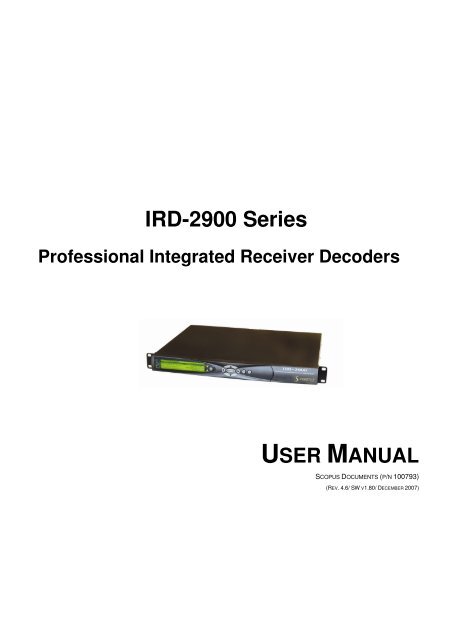
<strong>IRD</strong>-<strong>2900</strong> <strong>Series</strong><br />
<strong>Professional</strong> <strong>Integrated</strong> <strong>Receiver</strong> Decoders<br />
USER MANUAL<br />
SCOPUS DOCUMENTS (P/N 100793)<br />
(REV. 4.6/ SW V1.80/ DECEMBER 2007)
<strong>IRD</strong>-<strong>2900</strong> <strong>Series</strong><br />
<strong>Professional</strong> <strong>Integrated</strong> <strong>Receiver</strong> Decoders<br />
<strong>IRD</strong>-<strong>2900</strong> <strong>Series</strong><br />
<strong>Professional</strong> <strong>Integrated</strong> <strong>Receiver</strong> Decoders<br />
USER MANUAL<br />
SCOPUS DOCUMENTS (P/N 100793)<br />
(REV. 4.6/ SW V1.80/ DECEMBER 2007)
Scopus Video Networks Ltd.<br />
International Headquarters<br />
10 Ha’amal St., Park Afek<br />
Rosh Ha’ayin, 48092<br />
Israel<br />
Tel: (972)-3-900-7777<br />
Fax:(972)-3-900-7888<br />
Email: info@scopus.net<br />
Web: www.scopus.net<br />
DOCUMENT HISTORY<br />
VERSION DATE DETAILS<br />
Rev. 1.0 April 2005 <strong>IRD</strong>-<strong>2900</strong> v1.1<br />
Scopus Video Networks Inc.<br />
America<br />
3 Independence Way<br />
Princeton, NJ 08540.<br />
USA<br />
Tel: (609)-987-8090<br />
Fax:(609)-987-8095<br />
Email: info@scopususa.com<br />
Web: www.scopususa.com<br />
Rev. 1.4 June 2005 New features for SW v1.16<br />
Rev. 2.0 August 2005 New features for SW v1.18<br />
Rev. 2.5 January 2006 New features for SW v1.40<br />
Rev. 2.6 March 2006 New features for SW v1.45<br />
Rev. 2.7 March 2006 New features for SW v1.50<br />
Rev. 3.0 June 2006 New features for SW v1.55<br />
Rev. 4.0 September 2006 New features for SW v1.60<br />
Rev 4.5 June 2007 New features for SW v1.70<br />
Rev 4.6 December 2007 New features for SW v1.80<br />
© 2005 Scopus Video Networks Ltd. All rights reserved.<br />
Scopus Video Networks Ltd. Reserves the rights to alter the equipment specifications and descriptions in this publication without<br />
prior notice. No part of this publication shall be deemed to be part of any contract or warranty unless specifically incorporated by<br />
reference into such contract or warranty.<br />
The information contained herein is merely descriptive in nature, and does not constitute a binding offer for sale of the product<br />
described herein.<br />
File <strong>IRD</strong>-<strong>2900</strong> User Manual Rev 4.6.doc. Saved 12/6/2007 1:11:00 PM
Page ii (Rev. 4.6/ SW v1.80/ December 2007)
<strong>IRD</strong>-<strong>2900</strong> <strong>Series</strong><br />
<strong>Professional</strong> <strong>Integrated</strong> <strong>Receiver</strong> Decoders<br />
INTRODUCTION<br />
Scopus Video Networks Ltd. takes great pride in delivery of its products and<br />
makes every endeavor to ensure its clients full satisfaction.<br />
On behalf of the whole Scopus team, we would like to extend our<br />
congratulations on your investment in the <strong>IRD</strong>-<strong>2900</strong> <strong>Series</strong> of <strong>Professional</strong><br />
<strong>Integrated</strong> <strong>Receiver</strong> Decoders.<br />
MANUAL SCOPE AND STRUCTURE<br />
This manual is comprised of the following main chapters:<br />
1. OVERVIEW<br />
An introduction and general description of the product, including<br />
highlights, benefits & typical applications, functional & physical<br />
descriptions, and main capabilities & specifications.<br />
2. INSTALLATION<br />
All the required procedures for installing and activating the unit. The<br />
procedures include site preparation & requirements, installation in a 19"<br />
rack, cable connections, rear panel options, pin-out descriptions, initial<br />
settings, and the serviceability check.<br />
3. CONTROL INTERFACES<br />
Various control interfaces, common tools, screen or windows and<br />
examples.<br />
4. <strong>IRD</strong>-<strong>2900</strong> OPERATION AND MANAGEMENT<br />
The main section of this manual details screens and explaining every<br />
function and each parameter.<br />
5. APPENDICES<br />
The appendices in this manual cover the issues of software upgrade,<br />
aspect ratio configurations, warning massages, configuration file, and<br />
installation procedures in German and French.<br />
Scopus Documents (p/n 100793) Page i
TECHNICAL SUPPORT<br />
User Manual<br />
Overview<br />
In case of technical problems with the <strong>IRD</strong>-<strong>2900</strong> components, refer to additional<br />
system documentation. Usually, this may assist you to resolve technical<br />
difficulties.<br />
Call your local distributor for technical support if required.<br />
RETURNING FAULTY PARTS<br />
Before Returning an Item:<br />
• Request an RMA (Return Merchandise Authorization) tracking number from<br />
your local distributor.<br />
• Scopus Video Networks Support will assign the number; this must<br />
accompany the item being returned and is referred to in all correspondence.<br />
• Send the item to Scopus Video Networks with the number included in the<br />
accompanying documentation (shipping and customs forms).<br />
CUSTOMER SUPPORT POINT OF CONTACT (POC)<br />
Scopus Video Networks Ltd.<br />
International Headquarters<br />
10 Ha’amal St., Park Afek<br />
Rosh Ha’ayin, 48092<br />
Israel<br />
Tel: (972)-3-900-7777<br />
Fax:(972)-3-900-7888<br />
Email: support@scopus.net<br />
Web: www.scopus.net<br />
Scopus Video Networks Inc.<br />
Americas<br />
100 Overlook Center Drive, 3rd Floor<br />
Princeton, NJ 08540.<br />
Page ii (Rev. 4.6/ SW v1.80/ December 2007)<br />
USA<br />
Tel: (609)-987-8090<br />
Fax:(609)-987-8095
<strong>IRD</strong>-<strong>2900</strong> <strong>Series</strong><br />
<strong>Professional</strong> <strong>Integrated</strong> <strong>Receiver</strong> Decoders<br />
WARRANTY<br />
SCOPUS Video Networks Ltd. warrants that the product and any part thereof, including but<br />
not limited to spare parts will, when properly installed, conform to SCOPUS Video Networks<br />
Ltd. published specifications. Also, the product and any parts thereof, including but not limited<br />
to spare parts, will be free from defects deriving from faulty workmanship and faulty materials<br />
under standard use and service, for a period of twelve (12) months following the date of<br />
manufacture thereof.<br />
The supply of spare parts at a reasonable cost shall be available for a period of three (3) years<br />
from the date of delivery.<br />
This warranty does not cover ordinary wear and tear of the product or other defects due to<br />
circumstances beyond SCOPUS Video Networks Ltd. control, such as: unsuitable operating<br />
means, chemicals, electro-mechanical issues, or electrical influences and damages, which may<br />
be caused by interference by the CUSTOMER or any unauthorized third party.<br />
Defective cards and assemblies will be sent to SCOPUS Video Networks Ltd. for repair. The<br />
repaired cards and assemblies will be returned to the CUSTOMER within 30 days from their<br />
receipt by SCOPUS Video Networks Ltd.<br />
Cards and assemblies repaired during the twelve (12) month warranty period will carry a<br />
warranty of six (6) months from date of repair or until the end of original warranty period,<br />
whichever is the later date.<br />
SCOPUS Video Networks Ltd. sole liability under this warranty shall be limited to the repair or<br />
replacement with equivalent units at SCOPUS Video Networks Ltd. facilities, of any product or<br />
parts thereof that do not conform to SCOPUS Video Networks Ltd. published specifications or<br />
that are defective in material or workmanship, as specified above. The expense of installing<br />
repaired or replaced parts shall be borne by the CUSTOMER.<br />
SCOPUS Video Networks Ltd. sole obligation under this warranty is to be the supplier of the<br />
product to the CUSTOMER and to provide such services as set out in this warranty according<br />
to the SCOPUS Video Networks Ltd. terms and conditions provided for herein. In no event will<br />
SCOPUS Video Networks Ltd. be liable to the CUSTOMER for any: business expenses, loss of<br />
profits, or incidental, indirect, or consequential damages, however caused, unless such<br />
expenses, loss, or damages shall have derived from an infringement of patents of copyrights.<br />
THE WARRANTIES STATED HEREIN ARE EXCLUSIVE AND ARE EXPRESSLY IN LIEU OF ALL<br />
OTHER WARRANTIES, EXPRESSED OR IMPLIED, INCLUDING, BUT NOT LIMITED TO, THE<br />
IMPLIED WARRANTY OF MERCHANTABILITY OR FITNESS FOR A PARTICULAR PURPOSE.<br />
Beyond the warranty period, SCOPUS Video Networks Ltd. shall repair or replace defective<br />
cards and assemblies according to its standard and relevant price list at such time. Cards and<br />
assemblies thus repaired shall carry a warranty of six (6) months.<br />
COMPLIANCE EMC SAFETY<br />
EN55022 (CISPR 22) EN60950<br />
EN55024 (CISPR 24) CB (IEC60950)<br />
EN55013 (CISPR 13) UL60950<br />
EN55020 (CISPR 20) cTUVus<br />
FCC part 15 (class B)<br />
CB<br />
Scopus Documents (p/n 100793) Page iii
CE CERTIFICATION<br />
The <strong>IRD</strong>-<strong>2900</strong> meets all the CE Class A requirements.<br />
User Manual<br />
Overview<br />
In order to meet CE requirements, the following cables must be connected on all<br />
ASI outputs (when applicable). When cables are connected to these outputs<br />
then the device is compliant with the use of FAIR-RITE 0443164151.<br />
FCC COMPLIANCE NOTICE<br />
Trade Name Scopus<br />
Product Name <strong>Integrated</strong> <strong>Receiver</strong> Decoder<br />
Product Model Number <strong>IRD</strong>-<strong>2900</strong> <strong>Series</strong><br />
These devices comply with Part 15 of the FCC Rules.<br />
OPERATION IS SUBJECT TO THE FOLLOWING TWO CONDITIONS:<br />
• These devices do not cause harmful interference.<br />
• These devices must accept any interference received, including<br />
interference that may cause non relevant operation.<br />
The FCC Wants You to Know<br />
This equipment has been tested and found to comply with the limits for a<br />
Class A digital device, pursuant to Part 15 of the FCC rules. These limits are<br />
designed to provide reasonable protection against harmful interference when<br />
the equipment is operated in a commercial environment.<br />
This equipment generates, uses and can radiate radio frequency energy and,<br />
if not installed and used in accordance with the instructions, may cause<br />
harmful interference to radio communications.<br />
Operation of this equipment in a residential area is likely to cause harmful<br />
interference, in which case you will be required to correct the interference at<br />
your expense.<br />
FCC Warning<br />
Modifications not expressly approved by the manufacturer could void your<br />
authority to operate the equipment under FCC Rules.<br />
Page iv (Rev. 4.6/ SW v1.80/ December 2007)
<strong>IRD</strong>-<strong>2900</strong> <strong>Series</strong><br />
<strong>Professional</strong> <strong>Integrated</strong> <strong>Receiver</strong> Decoders<br />
WEEE/ROHS COMPLIANCE POLICY<br />
Scopus Video Networks Ltd. complies with the European Union's Directive<br />
2002/96/EC as amended by Directive 2003/108/EC, on Waste Electrical and<br />
Electronic Equipment, also known as “WEEE.” Scopus understands all of its<br />
products to fall under the WEEE Directive as IT and telecommunications<br />
equipment.<br />
Scopus will comply with the European Union's Directive 2002/95/EC on the<br />
Restriction of use of Hazardous Substances, also known as “RoHS”, by July 01,<br />
2006. All our products are either compliant or exempt from the RoHS Directive’s<br />
lead-free requirements as far as the use of lead in solders for network<br />
infrastructure equipment for switching, signaling, transmission as well as<br />
network management for telecommunication, is concerned.<br />
Scopus ensures that all products will either be re-used or recycled in compliance<br />
with the WEEE Directive.<br />
GREEN PROCUREMENT POLICY<br />
As part of its commitment to comply with global environmental initiatives,<br />
Scopus will continue to actively work with its supply chain to ensure the ongoing<br />
compliance with EU directives as well as the procurement and utilization of<br />
reliable, environmentally responsible alternatives to hazardous substances.<br />
WEEE RECYCLING<br />
The EU has set up targets for the recovery of waste from electric and electronic<br />
equipment (WEEE). In order to assist EU member states to preserve, protect<br />
and improve the quality of the environment, protect human health and utilize<br />
natural resources prudently and rationally, Scopus strives to recycle in<br />
compliance with the WEEE Directive any of its products that cannot be re-used.<br />
Scopus customers should:<br />
• Discard equipment in dedicated disposal areas only.<br />
• Arrange proper recycling of unneeded equipment, e.g. by re-using the<br />
equipment or giving it away to charity.<br />
• For the take-back of Scopus equipment, customers must act in accordance<br />
with the Scopus take-back policy, as provided in the website.<br />
Scopus Documents (p/n 100793) Page v
TABLE OF CONTENTS<br />
User Manual<br />
Overview<br />
Chapter 1. Overview........................................................ 1-1<br />
1.1. General Information.......................................................... 1-1<br />
1.2. Highlights and Benefits...................................................... 1-2<br />
1.3. Applications ..................................................................... 1-3<br />
1.4. Functionality .................................................................... 1-4<br />
1.5. Mechanical Structure ........................................................ 1-5<br />
1.5.1. Front Panel ...................................................................... 1-5<br />
1.5.2. Various Front-Ends ........................................................... 1-6<br />
1.5.3. Software Permission (Licensing) ......................................... 1-7<br />
1.5.4. <strong>IRD</strong>-<strong>2900</strong> models ............................................................. 1-8<br />
1.6. Management...................................................................1-17<br />
1.6.1. Local Management...........................................................1-17<br />
1.6.2. Remote Management .......................................................1-17<br />
1.7. Characteristics and Specifications ......................................1-18<br />
1.7.1. Transport Stream Interface Options ...................................1-18<br />
1.7.2. Advanced Processing .......................................................1-21<br />
1.7.3. Decoder Outputs .............................................................1-22<br />
1.7.4. Conditional Access...........................................................1-25<br />
1.7.5. Control and Monitoring.....................................................1-25<br />
1.7.6. Compliance.....................................................................1-26<br />
1.7.7. Environmental Conditions .................................................1-26<br />
1.7.8. Physical and Power Specifications ......................................1-27<br />
Chapter 2. Installation .................................................... 2-1<br />
2.1. Safety Precautions............................................................ 2-1<br />
2.1.1. Restricted Access Area ...................................................... 2-1<br />
2.1.2. Installation Codes............................................................. 2-1<br />
2.2. Inventory Check............................................................... 2-2<br />
2.3. Installation Instructions..................................................... 2-2<br />
2.3.1. Site Preparation ............................................................... 2-2<br />
2.3.2. Mechanical Rack Installation .............................................. 2-3<br />
2.3.3. Insertion of the DVB-CI Module (PCMCIA) ........................... 2-9<br />
2.4. Cable Connection.............................................................2-10<br />
2.5. Initialization And Configuration..........................................2-14<br />
2.5.1. Electrical Power Connection ..............................................2-14<br />
2.5.2. Powering Up ...................................................................2-16<br />
2.5.3. Tuning ...........................................................................2-16<br />
2.5.4. Performing Serviceability Check ........................................2-17<br />
Chapter 3. <strong>IRD</strong>-<strong>2900</strong> Control Interfaces.......................... 3-1<br />
3.1. Front Panel Control Interface ............................................. 3-1<br />
3.1.1. Controls and Displays........................................................ 3-1<br />
3.1.2. <strong>IRD</strong>-<strong>2900</strong> Front Panel Screen Types.................................... 3-3<br />
Page vi (Rev. 4.6/ SW v1.80/ December 2007)
<strong>IRD</strong>-<strong>2900</strong> <strong>Series</strong><br />
<strong>Professional</strong> <strong>Integrated</strong> <strong>Receiver</strong> Decoders<br />
3.1.3. <strong>IRD</strong>-<strong>2900</strong> Menu Tree......................................................... 3-8<br />
3.1.4. Front Panel Initialization Sequence ..................................... 3-9<br />
3.2. Web-Based Management Interface.................................... 3-11<br />
3.2.1. Controls and Displays...................................................... 3-12<br />
3.2.2. Initializing the Web-Based Management ............................ 3-17<br />
Chapter 4. Operation and Management ...........................4-1<br />
4.1. Preset ............................................................................. 4-1<br />
4.1.1. Recall Preset .................................................................... 4-3<br />
4.1.2. Save Current Preset .......................................................... 4-4<br />
4.1.3. Rename Preset ................................................................. 4-8<br />
4.1.4. Delete Preset ................................................................. 4-10<br />
4.1.5. Delete All Presets ........................................................... 4-12<br />
4.2. Configuration ................................................................. 4-13<br />
4.2.1. <strong>Receiver</strong> Modules............................................................ 4-14<br />
4.2.2. Satellite <strong>Receiver</strong> Modules ............................................... 4-15<br />
4.2.3. Stream Configuration Menu.............................................. 4-55<br />
4.2.4. Filtering......................................................................... 4-62<br />
4.2.5. Service Configuration Menu ............................................. 4-74<br />
4.2.6. Video Configuration Menu ................................................ 4-92<br />
4.2.7. Audio Configuration Menu ...............................................4-116<br />
4.2.8. Data Configuration Menu ................................................4-126<br />
4.2.9. GenLock Configuration ...................................................4-137<br />
4.2.10. Conditional Access Configuration Menu.............................4-139<br />
4.2.11. Unit Configuration Menu .................................................4-148<br />
4.3. Status ..........................................................................4-170<br />
4.3.1. <strong>Receiver</strong> Status .............................................................4-171<br />
4.3.2. Stream Status Menu ......................................................4-177<br />
4.3.3. Service Status...............................................................4-180<br />
4.3.4. Video Status Menu.........................................................4-180<br />
4.3.5. Audio Status Menu.........................................................4-184<br />
4.3.6. Data Status Menu ..........................................................4-186<br />
4.3.7. GenLock Status .............................................................4-188<br />
4.3.8. Conditional Access Status Menu.......................................4-188<br />
4.3.9. Unit Status Menu ...........................................................4-191<br />
Appendix A Software Download ........................................A-1<br />
A.1 Downloading Software Using FTP ........................................ A-1<br />
A.1.1 Introduction..................................................................... A-1<br />
A.1.2 Installation ...................................................................... A-1<br />
A.2 Loading Software to the <strong>IRD</strong>-<strong>2900</strong> through the Serial Port ..... A-6<br />
A.2.1 PC Connection to the Serial Port ......................................... A-6<br />
A.2.2 PC Serial-COM (Terminal) Software..................................... A-7<br />
A.2.3 Opening Hyperterminal from MS Windows ........................... A-7<br />
A.2.4 Defining the Communication .............................................. A-8<br />
A.2.5 Checking PC Terminal Communication with the <strong>IRD</strong> ............ A-10<br />
A.2.6 Installation: ................................................................... A-11<br />
Scopus Documents (p/n 100793) Page vii
User Manual<br />
Overview<br />
Appendix B IP-Front End Software Upgrade Procedure ....B-1<br />
Appendix C Aspect Ratio Configuration Process................ C-1<br />
C.1 General ........................................................................... C-1<br />
C.2 Aspect Ratio Conversion Machine........................................ C-1<br />
C.3 Table of Conversions......................................................... C-3<br />
Appendix D Configuration File...........................................D-1<br />
D.1 Introduction..................................................................... D-1<br />
D.2 Parameters...................................................................... D-1<br />
D.2.1 Stream Configurations ...................................................... D-1<br />
D.2.2 Service Configurations ...................................................... D-2<br />
D.2.3 Video Configurations ......................................................... D-3<br />
D.2.4 Audio Configurations......................................................... D-4<br />
D.2.5 Data Configurations .......................................................... D-4<br />
D.2.6 DVB S <strong>Receiver</strong> Configurations ........................................... D-4<br />
D.2.7 IP <strong>Receiver</strong> Configuration .................................................. D-5<br />
Appendix E Warning Messages ......................................... E-1<br />
E.1 General ........................................................................... E-1<br />
E.2 Warning leds.................................................................... E-1<br />
E.3 Warning messages ........................................................... E-2<br />
Appendix F Installation (deutsch) .................................... F-1<br />
F.1 Sicherheits-Vorsichtsmaßnahmen ........................................F-1<br />
F.1.1 Bereich mit beschränktem Zugang.......................................F-1<br />
F.2 Installations-Anweisungen ..................................................F-1<br />
F.2.1 Vorbereitung des Aufstellungsplatzes ...................................F-2<br />
F.2.2 Mechanische Installation des Gestells..................................F-2<br />
F.2.3 Einfügen des DVB-CI -Moduls (PCMCIA) ...............................F-7<br />
F.3 Kabel -Anschluss ...............................................................F-8<br />
F.4 Initialisierung und Konfiguration........................................F-13<br />
F.4.1 Anschluss an die Energieversorgung ..................................F-13<br />
F.4.2 Aufladen.........................................................................F-15<br />
F.4.3 Abstimmung ...................................................................F-16<br />
F.4.4 Durchführen der Nutzbarkeitsprüfung ................................F-16<br />
Appendix G Installation (française) ..................................G-1<br />
G.1 MESURES DE SECURITE .................................................... G-1<br />
G.2 Liste d’inventaire .............................................................. G-1<br />
G.3 Instructions d’Installation .................................................. G-2<br />
G.3.1 Préparation de l’emplacement ............................................ G-2<br />
G.3.2 Installation mécanique du rack........................................... G-3<br />
G.3.3 Insertion du module DVB-CI (PCMCIA)................................ G-8<br />
G.4 Connexion par Cable......................................................... G-8<br />
G.5 Initialisation et Configuration ........................................... G-13<br />
G.5.1 Connection à l’alimentation électrique ............................... G-13<br />
G.5.2 Démarrer ...................................................................... G-15<br />
G.5.3 Réglage......................................................................... G-15<br />
Page viii (Rev. 4.6/ SW v1.80/ December 2007)
<strong>IRD</strong>-<strong>2900</strong> <strong>Series</strong><br />
<strong>Professional</strong> <strong>Integrated</strong> <strong>Receiver</strong> Decoders<br />
G.5.4 Effectuer une vérification de fonctionnement...................... G-16<br />
LIST OF FIGURES<br />
Figure 1-1: Signal Path in the <strong>IRD</strong>-<strong>2900</strong> – Functionality Block Diagram ...... 1-4<br />
Figure 1-2: <strong>IRD</strong>-<strong>2900</strong> Unit.................................................................... 1-5<br />
Figure 1-3: Front View of the <strong>IRD</strong>.......................................................... 1-5<br />
Figure 1-4: <strong>IRD</strong>-2961 Rear Panel (IP Input interface) .............................. 1-6<br />
Figure 1-5: <strong>IRD</strong>-2961 Rear Panel (DVB-S Dual Input interface) ................. 1-6<br />
Figure 1-6: <strong>IRD</strong>-2961 Rear Panel (Decoder Only interface) ....................... 1-7<br />
Figure 1-7: <strong>IRD</strong>-2960 Rear Panel (Standard) .......................................... 1-8<br />
Figure 1-8: <strong>IRD</strong>-2961 Rear Panel .......................................................... 1-9<br />
Figure 1-9: <strong>IRD</strong>-2962 Rear Panel .........................................................1-10<br />
Figure 1-10: <strong>IRD</strong>-2963 Rear Panel .........................................................1-11<br />
Figure 1-11: <strong>IRD</strong>-2980 Rear Panel .........................................................1-12<br />
Figure 1-12: <strong>IRD</strong>-2981 Rear Panel .........................................................1-13<br />
Figure 1-13: <strong>IRD</strong>-2990 Rear Panel .........................................................1-14<br />
Figure 1-14: <strong>IRD</strong>-2991 Rear Panel .........................................................1-15<br />
Figure 1-15: <strong>IRD</strong>-2992 Rear Panel .........................................................1-16<br />
Figure 2-1: Pair of Scopus Rack Slides ................................................... 2-4<br />
Figure 2-2: Scopus Rack Slide Measurement Specifications....................... 2-5<br />
Figure 2-3: Laying the Device on the Rack-Slides .................................... 2-6<br />
Figure 2-4: Clipped Mounting Brackets................................................... 2-6<br />
Figure 2-5: Device Mounted on a Pair of Rack-Slides ............................... 2-7<br />
Figure 2-6: Multiple Devices Mounted on a Single Pair of Rack-Slides......... 2-8<br />
Figure 2-7: DVB-CI Module................................................................... 2-9<br />
Figure 2-8: <strong>IRD</strong>-2992 Rear Panel .........................................................2-10<br />
Figure 2-9: 9-Pin Male Connector Pin Numbering....................................2-11<br />
Figure 2-10: Power Supply Configurations and Rack-Mount Grounding Jackscrew<br />
.......................................................................................2-14<br />
Figure 2-11: DC Power Supply and Rack-Mount Grounding Jackscrew.........2-15<br />
Figure 3-1: Front Panel ........................................................................ 3-1<br />
Figure 3-2: <strong>IRD</strong>-<strong>2900</strong> Front Panel Menu (Root Menu) - Basic Structure ...... 3-8<br />
Figure 3-3: Web-Based Management Window – General View ..................3-11<br />
Figure 3-4: <strong>IRD</strong>-<strong>2900</strong> Web-Based Management Interface Screen (Example)3-12<br />
Figure 3-5: Web-Based Management Title .............................................3-13<br />
Figure 3-6: Web-Based Management Menu and Sub-Menu Tabs...............3-14<br />
Figure 3-7: Status Menu .....................................................................3-14<br />
Figure 3-8: Main-Menu Tabs ................................................................3-15<br />
Figure 3-9: Sub-Menu Tabs .................................................................3-15<br />
Figure 3-10: Edit-Value Parameter .........................................................3-16<br />
Scopus Documents (p/n 100793) Page ix
User Manual<br />
Overview<br />
Figure 3-11: Select-Value Parameter......................................................3-16<br />
Figure 3-12: Refresh Button ..................................................................3-17<br />
Figure 3-13: IP Address Field ................................................................3-18<br />
Figure 3-14: <strong>IRD</strong>-<strong>2900</strong> Web Management Access Box...............................3-19<br />
Figure 4-1: Web Interface Preset Screen.................................................4-2<br />
Figure 4-2: Web Interface Preset Recall Tab ............................................4-4<br />
Figure 4-3: Web Interface Save Preset Screen .........................................4-5<br />
Figure 4-4: Web Interface Save Tab .......................................................4-7<br />
Figure 4-5: Web Interface – Save Preset As New Name Tab ......................4-8<br />
Figure 4-6: Web Interface Rename Preset Screen ....................................4-9<br />
Figure 4-7: Web Interface – Rename Preset Tab ......................................4-9<br />
Figure 4-8: Web Interface Delete Preset Screen.....................................4-11<br />
Figure 4-9: Web Interface – Delete Preset Tab.......................................4-11<br />
Figure 4-10: <strong>IRD</strong>-<strong>2900</strong> Configuration Main Menu .....................................4-13<br />
Figure 4-11: DVB-S <strong>Receiver</strong> Parameters Menu Screen.............................4-16<br />
Figure 4-12: DVB-S2 <strong>Receiver</strong> Parameters Menu Screen ...........................4-25<br />
Figure 4-13: DVB-DSNG <strong>Receiver</strong> Parameters Menu Screen ......................4-36<br />
Figure 4-14: DVB-IP <strong>Receiver</strong> – MPEGoIP 1 Parameters Menu Screen .........4-45<br />
Figure 4-15: DVB-IP <strong>Receiver</strong> – General Parameters Menu Screen .............4-51<br />
Figure 4-16: Stream Configuration Menu ................................................4-55<br />
Figure 4-17: Stream Parameters Menu Screen.........................................4-56<br />
Figure 4-18: Filtering Parameters web-management screen ......................4-63<br />
Figure 4-19: General Filtering Parameters Menu Screen............................4-64<br />
Figure 4-20: Select Service Menu Screen ................................................4-68<br />
Figure 4-21: Select PIDs Menu Screen....................................................4-72<br />
Figure 4-22: Service Configuration Menu ................................................4-74<br />
Figure 4-23: TV1 Menu Screen ..............................................................4-77<br />
Figure 4-24: Preferred Language Screen.................................................4-81<br />
Figure 4-25: PID Select Menu Screen .....................................................4-85<br />
Figure 4-26: Port to Service Menu Screen ...............................................4-88<br />
Figure 4-27: General Service Menu Screen..............................................4-90<br />
Figure 4-28: Video Configuration Menu...................................................4-92<br />
Figure 4-29: Video 1 Menu Screen .........................................................4-95<br />
Figure 4-30: VBI 1 Parameters ............................................................ 4-102<br />
Figure 4-31: OSD1 Menu Screen.......................................................... 4-112<br />
Figure 4-32: Audio Configuration Menu................................................. 4-116<br />
Figure 4-33: Audio 1 Menu Screen ....................................................... 4-119<br />
Figure 4-34: Data Configuration Menu .................................................. 4-126<br />
Figure 4-35: IP Data Port Menu Screen................................................. 4-131<br />
Figure 4-36: Web Interface Genlock Screen .......................................... 4-137<br />
Figure 4-37: Conditional Access Configuration Menu............................... 4-139<br />
Figure 4-38: Web Interface Conditional Access Screen............................ 4-140<br />
Figure 4-39: Web Interface Common Interface Screen ........................... 4-141<br />
Page x (Rev. 4.6/ SW v1.80/ December 2007)
<strong>IRD</strong>-<strong>2900</strong> <strong>Series</strong><br />
<strong>Professional</strong> <strong>Integrated</strong> <strong>Receiver</strong> Decoders<br />
Figure 4-40: Web Interface BISS Screen...............................................4-145<br />
Figure 4-41: Unit Configuration Menu ...................................................4-148<br />
Figure 4-42: Web Interface - Unit Screen..............................................4-149<br />
Figure 4-43: Soft Reset Web-Interface Screen .......................................4-151<br />
Figure 4-44: Change Password Screen..................................................4-151<br />
Figure 4-45: Control Password Screen ..................................................4-152<br />
Figure 4-46: Unit Serial Screen............................................................4-153<br />
Figure 4-47: Unit Ethernet Screen........................................................4-156<br />
Figure 4-48: <strong>IRD</strong>-<strong>2900</strong> Licensing Screen ...............................................4-158<br />
Figure 4-49: Alarms Web-Interface Screen............................................4-165<br />
Figure 4-50: GPI Web-Interface Screen ................................................4-166<br />
Figure 4-51: Web Interface – Traps Screen ...........................................4-167<br />
Figure 4-52: Add New Trap Destination.................................................4-169<br />
Figure 4-53: Delete Trap Destination ....................................................4-169<br />
Figure 4-54: Modify Trap Destination....................................................4-169<br />
Figure 4-55: <strong>IRD</strong>-<strong>2900</strong> Status Screen...................................................4-171<br />
Figure 4-56: <strong>IRD</strong>-<strong>2900</strong> DVBS Status Screen ..........................................4-172<br />
Figure 4-57: <strong>IRD</strong>-<strong>2900</strong> DVBS2 Status Screen ........................................4-174<br />
Figure 4-58: <strong>IRD</strong>-<strong>2900</strong> DVB IP Status Screen ........................................4-175<br />
Figure 4-59: <strong>IRD</strong>-<strong>2900</strong> Stream Status Screen........................................4-177<br />
Figure 4-60: <strong>IRD</strong>-<strong>2900</strong> Service Status Screen........................................4-180<br />
Figure 4-61: <strong>IRD</strong>-<strong>2900</strong> Video Status Screen ..........................................4-181<br />
Figure 4-62: <strong>IRD</strong>-<strong>2900</strong> Audio Status Screen ..........................................4-184<br />
Figure 4-63: <strong>IRD</strong>-<strong>2900</strong> IP Data Port Status Screen .................................4-187<br />
Figure 4-64: <strong>IRD</strong>-<strong>2900</strong> Unit Status Screen ............................................4-191<br />
Figure 4-65: Unit – Identity (Status Screen)..........................................4-192<br />
Figure 4-66: Unit – Versions (Status Screen).........................................4-192<br />
Figure 4-67: Unit – Monitoring (Status Screen).....................................4-193<br />
Figure 4-68: Web-Management: Licensing ............................................4-195<br />
Figure A-1: Start Menu – Select Run...................................................... A-2<br />
Figure A-2: Run Dialog Box................................................................... A-3<br />
Figure A-3: Open FTP Session ............................................................... A-3<br />
Figure A-4: Login to FTP....................................................................... A-4<br />
Figure A-5: Access Bin Folder................................................................ A-4<br />
Figure A-6: Loading the File.................................................................. A-5<br />
Figure A-7: Start Menu – Open HyperTerminal ........................................ A-8<br />
Figure A-8: HyperTerminal – Enter Connection........................................ A-9<br />
Figure A-9: Select PC COM Port............................................................. A-9<br />
Figure A-10: Port Settings Tab.............................................................. A-10<br />
Figure A-11: HyperTerminal Window...................................................... A-11<br />
Figure A-12: Update Software Version Command .................................... A-12<br />
Figure A-13: Erasing Flash Process ........................................................ A-13<br />
Figure A-14: Ready to Receive New Software ......................................... A-14<br />
Scopus Documents (p/n 100793) Page xi
User Manual<br />
Overview<br />
Figure A-15: Send File Dialog Box ..........................................................A-15<br />
Figure A-16: Sending Status Dialog Box..................................................A-15<br />
Figure A-17: <strong>IRD</strong> Boot Application Starts.................................................A-16<br />
Figure A-18: Complete Software Loading ................................................A-17<br />
Figure C-1: Aspect Ratio Conversion Machine.......................................... C-2<br />
Figure C-2: Normal 4:3 Aspect Ratio...................................................... C-3<br />
Figure C-3: Normal 16:9 Aspect Ratio................................................... C-4<br />
Figure E-1: Front panel warning LEDs .....................................................E-1<br />
Abbildung 1-2: Paar Scopus- Gleitschienen..................................................F-3<br />
Abbildung 1-3: Maßspezifikationen der Scopus- Gleitschienen........................F-4<br />
Abbildung 1-4: Auflegen des Geräts auf die Gleitschienen ..............................F-5<br />
Abbildung 1-5: Angeklemmte Montageträger ................................................F-5<br />
Abbildung 1-6: Auf einem Paar Gleitschienen montiertes Gerät .......................F-6<br />
Abbildung 1-7: Mehrfache auf einem einzigen Paar Gleitschienen montierte Geräte...................F-7<br />
Abbildung 1-8: DVB-CI -Modul ....................................................................F-8<br />
Abbildung 1-9: <strong>IRD</strong>-2992- Tafel auf der Rückseite .........................................F-8<br />
Abbildung 1-10: Nummerierung des 9 Stift-Verbindungssteckers .................... F-10<br />
Abbildung 1-11: Energieversorgungs-Konfigurationen und Gestellmontage-Erdungs-Schraubenwinde<br />
(jackscrew).......................................................................... F-14<br />
Abbildung 1-12: Gleichstrom-Energieversorgung und Gestellmontage-Erdungsschraubenwinde<br />
(Jackscrew) ......................................................................... F-15<br />
Image G-1: Paire de Rack Slides de Scopus ........................................... G-3<br />
Figure G-2: Spécifications de dimensions des rack-slides de Scopus........... G-4<br />
Figure G-3: poser l’appareil sur les Rack-Slides ....................................... G-5<br />
Figure G-4: Crochets d’assemblage attachés........................................... G-5<br />
Figure G-5: Appareil monté sur une paire de Rack-Slides ......................... G-6<br />
Figure G-6: Plusieurs appareils montés sur une simple paire de Rack-Slides G-7<br />
Figure G-7: DVB-CI Module................................................................... G-8<br />
Image G-8: Panneau arrière d’<strong>IRD</strong>-2992................................................. G-9<br />
Figure G-9: 9-Pin connecteur male de numérotation des pins.................. G-10<br />
Figure G-10: Configuration d’alimentation électrique et vis de contact a la masse<br />
de montage sur rack......................................................... G-14<br />
Figure G-11: Alimentation électrique DC et vis de contact à la masse ........ G-15<br />
Page xii (Rev. 4.6/ SW v1.80/ December 2007)
<strong>IRD</strong>-<strong>2900</strong> <strong>Series</strong><br />
<strong>Professional</strong> <strong>Integrated</strong> <strong>Receiver</strong> Decoders<br />
LIST OF TABLES<br />
Table 2-1: <strong>IRD</strong>-<strong>2900</strong> Rear Panel – Connectors and Cables......................2-10<br />
Table 2-2: RS-232/RS-485 Control Connector Pin-Out ...........................2-12<br />
Table 2-3: RS-232 Low Speed Data and GPI Pin-Out .............................2-12<br />
Table 2-4: RS-422 High Speed Data Pin-Out.........................................2-12<br />
Table 2-5: Audio 3-4 Breakout Cable Pin-Out (Scopus P/N 204346).........2-13<br />
Table 2-6: AES/EBU Balanced Breakout Cable Pin-Out (Scopus P/N 204345)2-13<br />
Table 2-7: <strong>IRD</strong>-<strong>2900</strong> Serviceability Check ...........................................2-17<br />
Table 4-1: Band Frequency Range.......................................................4-17<br />
Table 4-2: Band Frequency Designations..............................................4-26<br />
Table 4-3: <strong>IRD</strong>-<strong>2900</strong> Rear Panel – Connectors and Cables......................4-29<br />
Table 4-3: Band Frequency Range.......................................................4-37<br />
Table C-1: Table of Conversions - 4:3 Stream Option ............................. C-4<br />
Table C-2: Table of Conversions - 16:9 Options ..................................... C-6<br />
Tabelle 1-3: Hintere Tafel des <strong>IRD</strong>-<strong>2900</strong> – Steckverbindungen und Kabel ...F-9<br />
Tabelle 1-4: Konfiguration und Funktion eines jeden Stiftes des RS-232/RS-485 -<br />
Verbindungsstücks .................................................................F-11<br />
Tabelle 1-5: Konfigurationen und Funktion eines jeden Stiftes der RS-232-<br />
Niedriggeschwindigkeitsdaten und der Graphikprozedur-Schnittstelle .........F-11<br />
Tabelle 1-6: RS-422 Konfigurationen und Funktion eines jeden Stiftes der<br />
Hochgeschwindigkeitsdaten ................................................F-12<br />
Tabelle 1-7: Konfiguration und Funktion eines jeden Stiftes des Audio 3-4 –<br />
Aufschlüsselungskabels (Scopus P/N 204346) .......................F-12<br />
Tabelle 1-8: Konfiguration und die Funktion eines jeden Stiftes des<br />
vorgesteuerten Aufschlüsselungskabels (Scopus P/N 204345)...F-12<br />
Tabelle 1-9: <strong>IRD</strong>-<strong>2900</strong> –Nutzbarkeits-Prüfung .........................................F-16<br />
Tableau G-1: Panneau arrière d’<strong>IRD</strong>-<strong>2900</strong> – Connecteurs et câbles .............. G-9<br />
Tableau G-2: RS-232/RS-485 Control Connector Pin-Out .......................... G-11<br />
Tableau G-3: RS-232 données a faible vitesse et GPI Pin-Out .................... G-11<br />
Tableau G-4: RS-422 Données de vitesse élevée Pin-Out .......................... G-12<br />
Tableau G-5: Pin-Out cable à fibre optique Audio 3-4 (Scopus P/N 204346) G-12<br />
Tableau G-6: AES/EBU pin-out de câbles à fibres optiques équilibrés (Scopus P/N<br />
204345) ........................................................................... G-12<br />
Tableau G-7: <strong>IRD</strong>-<strong>2900</strong> vérification de fonctionnement ............................ G-16<br />
Table A-1: RS-232 Control Cable Pin-to-Pin ........................................... A-6<br />
Table A-2: RS-485 Control Cable Pin-to-Pin Designations ........................ A-7<br />
Scopus Documents (p/n 100793) Page xiii
<strong>IRD</strong>-<strong>2900</strong> <strong>Series</strong><br />
<strong>Professional</strong> <strong>Integrated</strong> <strong>Receiver</strong> Decoders<br />
Chapter 1.<br />
OVERVIEW<br />
1.1. GENERAL INFORMATION<br />
The <strong>IRD</strong>-<strong>2900</strong> professional MPEG-2 DVB and ATSC processing platform is<br />
designed to meet even the most demanding application requirements while<br />
maximizing ease of use and flexibility. With a graphical front-panel display, the<br />
<strong>IRD</strong>-<strong>2900</strong> <strong>Series</strong> includes:<br />
• Variety of Telco and cable front-end options<br />
• MPEG-over-IP inputs<br />
• MPEG-over-IP output<br />
• ASI transport-stream input<br />
• SNMP and web based management support<br />
The <strong>IRD</strong>-<strong>2900</strong> <strong>Series</strong> concurrently decodes up to two video programs from the<br />
transport stream.<br />
The <strong>IRD</strong>-<strong>2900</strong> <strong>Series</strong> features the following product lines:<br />
• <strong>IRD</strong>-296x - <strong>Professional</strong> single 4:2:0 decoder <strong>IRD</strong><br />
• <strong>IRD</strong>-298x - <strong>Professional</strong> single 4:2:0/4:2:2 decoder <strong>IRD</strong><br />
• <strong>IRD</strong>-299x - <strong>Professional</strong> dual 4:2:0 decoders <strong>IRD</strong>-<strong>2900</strong><br />
Housed in a true 1RU slim-line chassis and featuring low power consumption,<br />
the <strong>IRD</strong>-<strong>2900</strong> fully integrates with the Scopus product platform.<br />
Scopus Documents (p/n 100793) Page 1-1
1.2. HIGHLIGHTS AND BENEFITS<br />
The processing platform’s main features and options include:<br />
• MPEG2 4:2:0/4:2:2 decoder<br />
• H.264 4:2:0 field upgradeable using Scopus-Neotion module<br />
User Manual<br />
Overview<br />
• Variety of front-end options including DVB-S, DVB-S2, DVB-DSNG, G.703,<br />
MPEG-over-IP and DS3-ATM<br />
• DVB-S2 professional<br />
• MPEG-over-IP (MPEGoIP) inputs supporting up to 44Mbps (SPTS and MPTS)<br />
• Configurable De-Jitter delay<br />
• Physical Link Redundancy<br />
• Logical Source Redundancy<br />
• FEC (Forward Error Correction) ProMPEG CoP3v2<br />
• MPEGoIP output supporting up to 60Mbps<br />
• IP-over-MPEG output up to 60 Mbps (MPE decapsulation)<br />
• 1 or 2 L-Band inputs<br />
• ASI transport stream input and output<br />
• Service and PID Filtering over the ASI and IP outputs (dynamic and static<br />
modes)<br />
• DVB common interface (2 slots – 1 active simultaneously)<br />
• SDI, AES/EBU and analogue outputs<br />
• Up to 4 pairs of audio outputs supporting:<br />
• Musicam<br />
• Dolby Digital ® AC-3 Pass-Through<br />
• Dolby Digital ® AC-3 2.0 Down Mixing<br />
• Linear PCM Audio and Dolby-E Pass-Through (up to 3 outputs)<br />
• Embedded audio in SDI and re-insertion of VBI<br />
• VBI re-insertion in composite and SDI<br />
• Genlock for high-end accurate frame synchronization and phase<br />
compensation.<br />
• Redundancy support, 2 GPI Dry Contact relays with separate control<br />
• OSD (On-Screen Display) subtitling<br />
• Various of management interfaces: Graphical front-panel, user-friendly Web-<br />
Interface, command-line-interface (CLI) and SNMP<br />
• SW permission mechanism enables future upgrade<br />
• 50 different user defined setups<br />
Page 1-2 (Rev. 4.6/ SW v1.80/ December 2007)
<strong>IRD</strong>-<strong>2900</strong> <strong>Series</strong><br />
<strong>Professional</strong> <strong>Integrated</strong> <strong>Receiver</strong> Decoders<br />
1.3. APPLICATIONS<br />
The <strong>IRD</strong>-<strong>2900</strong> processing platform is a technologically advanced choice for a<br />
wide range of applications. Some typical uses include:<br />
• Digital turnaround<br />
• CATV IP head-end receiver/decoder<br />
• CATV IP distribution edge decoder<br />
• Satellite distribution<br />
• Telco distribution<br />
• DSNG<br />
• Syndication<br />
Scopus offers this series of professional <strong>IRD</strong>s in a wide range of standard<br />
configurations, with the flexibility to select specific interfaces and applicable<br />
required features.<br />
Scopus Documents (p/n 100793) Page 1-3
1.4. FUNCTIONALITY<br />
User Manual<br />
Overview<br />
The TS Router block receives input streams from an available source, for<br />
example: L-Band, MPEG-over-IP IN and ASI IN. Then the block routes the<br />
selected input to the Master and Slave decoders. Each decoder decodes one<br />
program from the input stream, routed by the TS router block, and provides<br />
decoded digital audio and video streams. These streams are provided to the<br />
Video Router block that routes them to the relevant outputs as well as to the<br />
analog video output. The Analog Video Output receives a digital video, converts<br />
the digital video into analog video, and outputs the analog video. The analog<br />
and digital audio output component outputs the digital and analog audio.<br />
Figure 1-1: Signal Path in the <strong>IRD</strong>-<strong>2900</strong> – Functionality Block Diagram<br />
Page 1-4 (Rev. 4.6/ SW v1.80/ December 2007)
<strong>IRD</strong>-<strong>2900</strong> <strong>Series</strong><br />
<strong>Professional</strong> <strong>Integrated</strong> <strong>Receiver</strong> Decoders<br />
1.5. MECHANICAL STRUCTURE<br />
The <strong>IRD</strong>-<strong>2900</strong> is housed in a rugged industrial enclosure, 1RU by 19" (rack<br />
mount).<br />
Figure 1-2: <strong>IRD</strong>-<strong>2900</strong> Unit<br />
1.5.1. Front Panel<br />
The front panel allows control using a four-way touch pad, [Enter] key, [Esc]<br />
key, and two programmable [F1]/[F2] keys. Operational commands and<br />
parameters are displayed on a graphical LCD. The four-way touch pad allows<br />
parameter modification and scrolling through the embedded VBI menus. Two<br />
LEDs show the WARNING and PWR/FAIL status (see Figure 1-3).<br />
Figure 1-3: Front View of the <strong>IRD</strong><br />
Scopus Documents (p/n 100793) Page 1-5
1.5.2. Various Front-Ends<br />
<strong>IRD</strong>-<strong>2900</strong> supports the following interfaces:<br />
• DVB-S Single L-Band input<br />
• DVB-S Dual L-Band input<br />
• DVB-DSNG Dual L-Band input<br />
• DVB-S2 Dual L-Band input<br />
• MPEG over IP (MPEGoIP) dual input<br />
• G.703 E3 single input with Loop-through<br />
• ASI-In Decoder only (except for <strong>IRD</strong>-2960)<br />
User Manual<br />
Overview<br />
In this manual all rear panels are displayed with the DVB-S interface. Each<br />
model has standard features and interfaces as well as features requiring active<br />
software licenses.<br />
The MPEGoIP input interface can be supported by all <strong>IRD</strong>-<strong>2900</strong> devices. Figure<br />
1-4 illustrates the <strong>IRD</strong>-2961 rear panel with an MPEGoIP input interface.<br />
Figure 1-4: <strong>IRD</strong>-2961 Rear Panel (IP Input interface)<br />
Figure 1-5 illustrates the <strong>IRD</strong>-2961 rear panel with DVB-S (QPSK) Dual Input<br />
configuration.<br />
Figure 1-5: <strong>IRD</strong>-2961 Rear Panel (DVB-S Dual Input interface)<br />
Figure 1-6 displays the <strong>IRD</strong>-2961 rear panel with Decoder Only configuration.<br />
Page 1-6 (Rev. 4.6/ SW v1.80/ December 2007)
<strong>IRD</strong>-<strong>2900</strong> <strong>Series</strong><br />
<strong>Professional</strong> <strong>Integrated</strong> <strong>Receiver</strong> Decoders<br />
Figure 1-6: <strong>IRD</strong>-2961 Rear Panel (Decoder Only interface)<br />
NOTE<br />
<strong>IRD</strong>-<strong>2900</strong> models supporting MPEGoIP output and IP data out (MPE<br />
de-capsulation) output can be configured to support either MPEGoIP or IP data<br />
out.<br />
1.5.3. Software Permission (Licensing)<br />
Each <strong>IRD</strong>-<strong>2900</strong> model is provided with a basic feature package. In order to suit<br />
specific requirements, additional license-permitted features are available. The<br />
Next chapter specifies the basic and optional features available for each model.<br />
In order to enable optional features perform one of the following:<br />
NOTE<br />
• Upon unit ordering - order the relevant features. The unit will be<br />
provided with the ordered features enabled.<br />
• After unit ordering - order the relevant features. In this case, a 16<br />
character key issued by Scopus video networks will be provided. The<br />
key must be entered to the unit thru the front-panel or the web-<br />
interface. For details see section 4.2.11.6<br />
When RS-232 low-speed-data and/or RS-422 high-speed-data are enabled<br />
the PID Filtering is unavailable.<br />
Scopus Documents (p/n 100793) Page 1-7
1.5.4. <strong>IRD</strong>-<strong>2900</strong> models<br />
1.5.4.1. <strong>IRD</strong>-2960 Interfaces and Features<br />
User Manual<br />
Overview<br />
The <strong>IRD</strong>-2960 is a single 4:2:0 Decoder <strong>IRD</strong>. The <strong>IRD</strong>-296x devices consist of<br />
two composite video interfaces. The CVBS #1 connector is used for broadcasting<br />
quality video and the CVBS #2 connector is used for monitoring.<br />
Figure 1-7 illustrates the <strong>IRD</strong>-2960 rear panel. The <strong>IRD</strong>-2960 basic features and<br />
software-licensed features are also detailed.<br />
Figure 1-7: <strong>IRD</strong>-2960 Rear Panel (Standard)<br />
Basic Features<br />
• 1 composite video - Broadcast<br />
quality (upper connector)<br />
• 1 composite video - Monitoring<br />
quality (lower connector)<br />
• 2 active analog – audio - stereo<br />
• GPI<br />
NOTES<br />
balanced interfaces<br />
Software-Licensed Features<br />
• Dolby digital (AC-3) LT/RT<br />
downmixing<br />
• RS-232 low speed data output<br />
• RS-422 high speed data output<br />
• H.264 (Scopus-Neotion module)<br />
• DVB-S2 Advance Modulation<br />
(optional)<br />
The <strong>IRD</strong>-2960 does not support the Decoder Only configuration.<br />
The Russian SECAM D/K (composite video only) is available only through Special<br />
orders.<br />
Page 1-8 (Rev. 4.6/ SW v1.80/ December 2007)
<strong>IRD</strong>-<strong>2900</strong> <strong>Series</strong><br />
<strong>Professional</strong> <strong>Integrated</strong> <strong>Receiver</strong> Decoders<br />
1.5.4.2. <strong>IRD</strong>-2961 Interfaces and Features<br />
The <strong>IRD</strong>-2961 is a single 4:2:0 decoder <strong>IRD</strong>. The <strong>IRD</strong>-296x family consists of<br />
two composite video interfaces. The CVBS #1 connector is used for broadcast<br />
quality video and the CVBS #2 connector is used for monitoring.<br />
Figure 1-8 illustrates the <strong>IRD</strong>-2961 rear panel. The <strong>IRD</strong>-2961 basic features and<br />
software-licensed features are also detailed.<br />
Figure 1-8: <strong>IRD</strong>-2961 Rear Panel<br />
Basic Features<br />
• 1 composite video - Broadcast<br />
quality (upper connector)<br />
• 1 composite video - Monitoring<br />
quality (lower connector)<br />
• 2 active analog – audio - stereo<br />
balanced interfaces<br />
• SNMP management (10/100 Base-T)<br />
• Web based management<br />
• GPI<br />
(10/100Base-T)<br />
NOTES<br />
Software-Licensed Features<br />
• ASI Input<br />
• Dual (identical) ASI outputs<br />
• MPEG-over-IP output or IP data<br />
output (MPE de-capsulation)<br />
• Dolby Digital (AC-3) LT/RT<br />
downmixing<br />
• Pro MPEG FEC<br />
• IP Dual input (link and source<br />
redundancy<br />
• PID and service filtering<br />
• RS-232 low speed data output<br />
• H.264 (Scopus-Neotion module)<br />
• DVB-S2 Advance Modulation<br />
(optional)<br />
In the case of power failure or system shutdown, ASI OUT 1 output will become<br />
ASI loop-through. Use ASI OUT 1 output for cascading a chain of <strong>IRD</strong>-<strong>2900</strong>.<br />
The Russian SECAM D/K (composite video only) is available only through special<br />
orders.<br />
Scopus Documents (p/n 100793) Page 1-9
1.5.4.3. <strong>IRD</strong>-2962 Interfaces and Features<br />
User Manual<br />
Overview<br />
The <strong>IRD</strong>-2962 is a single 4:2:0 decoder. The entire <strong>IRD</strong>-296x family consists of<br />
two composite video interfaces. The CVBS #1 connector is used for broadcast<br />
quality video and the CVBS #2 connector can is for monitoring.<br />
Figure 1-9 illustrates the <strong>IRD</strong>-2962 rear panel. The <strong>IRD</strong>-2962 basic features and<br />
software-licensed features are also detailed.<br />
Figure 1-9: <strong>IRD</strong>-2962 Rear Panel<br />
Basic Features<br />
• 1 composite video - Broadcast<br />
quality (upper connector)<br />
• 1 composite video - Monitoring<br />
quality (lower connector)<br />
• 2 SDI interfaces<br />
• Embedded VBI and up to 2 stereo<br />
channels in SDI<br />
• 2 activated analog-audio-stereo<br />
balanced interfaces<br />
• 2 activated AES/EBU-SPDIF audio-<br />
unbalanced interfaces<br />
• SNMP management (10/100 Base-T)<br />
• Web-based management (10/100<br />
• GPI<br />
Base-T)<br />
• Front panel A/V monitoring<br />
NOTE<br />
connectors<br />
Software-Licensed Features<br />
• ASI Input<br />
• Dual (identical) ASI outputs<br />
• MPEG-over-IP output or IP data<br />
output (MPE de-capsulation)<br />
• Genlock input and loop-through<br />
output<br />
• Dolby Digital (AC-3) LT/RT<br />
downmixing.<br />
• Pro MPEG FEC<br />
• PID and service filtering<br />
• H.264 (One Program Only)<br />
• RS-232 low speed data output<br />
• H.264 (Scopus-Neotion module)<br />
• DVB-S2 Advance Modulation<br />
(optional)<br />
In the case of power failure or system shutdown, ASI OUT 1 output will become<br />
ASI loop-through. Use ASI OUT 1 output for cascading a chain of <strong>IRD</strong>-<strong>2900</strong>.<br />
Page 1-10 (Rev. 4.6/ SW v1.80/ December 2007)
<strong>IRD</strong>-<strong>2900</strong> <strong>Series</strong><br />
<strong>Professional</strong> <strong>Integrated</strong> <strong>Receiver</strong> Decoders<br />
1.5.4.4. <strong>IRD</strong>-2963 Interfaces and Features<br />
The <strong>IRD</strong>-2963 is a single 4:2:0 decoder. The entire <strong>IRD</strong>-296X family consists of<br />
two composite video interfaces. The CVBS #1 connector is used for broadcast<br />
quality video and the CVBS #2 connector is used for monitoring.<br />
Figure 1-10 illustrates the <strong>IRD</strong>-2963 rear panel. The <strong>IRD</strong>-2963 basic features<br />
and software-licensed features are described below.<br />
Figure 1-10: <strong>IRD</strong>-2963 Rear Panel<br />
Basic Features<br />
• 1 composite video - Broadcast<br />
quality (upper connector)<br />
• 1 composite video - Monitoring<br />
quality (lower connector)<br />
• 2 SDI interfaces<br />
• Embedded VBI and up to 2 stereo<br />
channels in SDI<br />
• 2 active analog-audio-stereo<br />
balanced interfaces<br />
• 2 active AES/EBU-SPDIF audio-<br />
balanced interfaces<br />
• SNMP management (10/100 Base-T)<br />
• Web-based management (10/100<br />
• GPI<br />
Base-T)<br />
• Front panel A/V monitoring<br />
connectors<br />
NOTES<br />
Software-Licensed Features<br />
• ASI input<br />
• Dual (identical) ASI output<br />
• MPEG-over-IP output or IP data<br />
output (MPE de-capsulation)<br />
• Genlock input and loop-through<br />
output<br />
• Dolby Digital (AC-3) LT/RT<br />
downmixing<br />
• Pro MPEG FEC<br />
• IP Dual input (link and source<br />
redundancy<br />
• PID and service filtering<br />
• RS-232 low speed data output<br />
• H.264 (Scopus-Neotion module)<br />
• DVB-S2 Advance Modulation<br />
(optional)<br />
This model requires a breakout cable to connect to the AES/EBU interfaces.<br />
In case of power failure or system shutdown, ASI OUT 1 output will become ASI<br />
loop-through. Use ASI OUT 1 output for cascading a chain of <strong>IRD</strong>-<strong>2900</strong><br />
Scopus Documents (p/n 100793) Page 1-11
1.5.4.5. <strong>IRD</strong>-2980 Interfaces and Features<br />
User Manual<br />
Overview<br />
The <strong>IRD</strong>-2980 is a single 4:2:0/4:2:2 decoder. The <strong>IRD</strong>-298x family consists<br />
of two composite video interfaces. Both CVBS #1 and CVBS #2 connectors are<br />
for broadcast quality video. Figure 1-11 illustrates the <strong>IRD</strong>-2980 rear panel. The<br />
<strong>IRD</strong>-2980 basic and software-licensed features are also detailed.<br />
Figure 1-11: <strong>IRD</strong>-2980 Rear Panel<br />
Basic Features<br />
• 2 composite video interfaces –<br />
Broadcast quality<br />
• 2 SDI interfaces<br />
• Embedded VBI and up to 4<br />
stereo channels in SDI<br />
• Decoding 4:2:2 PP@ML (1.5–50<br />
Mbps)<br />
• 2 out of 4 active analog-audio-<br />
stereo balanced interfaces<br />
• 2 out of 4 active AES/EBU-SPDIF<br />
audio unbalanced interfaces<br />
• 1 ST and 2 ND active AES/EBU-<br />
SPDIF<br />
• SNMP management (10/100<br />
Base-T)<br />
• Web-based management (10/100<br />
• GPI<br />
Base-T)<br />
• Front panel A/V monitoring<br />
connectors<br />
NOTES<br />
Software-Licensed Features<br />
• ASI input<br />
• Dual (identical) ASI output<br />
• MPEG-over-IP output or IP data<br />
output (MPE de-capsulation)<br />
• 3 RD Active analog stereo pair<br />
• 4 TH Active analog stereo pair<br />
• 3 RD Active AES/EBU-SPDIF<br />
• 4 TH Active AES/EBU-SPDIF<br />
• Dolby Digital (AC-3) LT/RT<br />
downmixing<br />
• Linear PCM (SMPTE 302M 2000),<br />
Dolby-E pass-through<br />
• Pro MPEG FEC<br />
• IP Dual input (link and source<br />
redundancy<br />
• PID and service filtering<br />
• RS-232 low speed data output<br />
• DVB-S2 Advance Modulation<br />
(optional)<br />
This model requires a breakout cable to connect to the 3 rd and 4 th analog stereo<br />
pairs.<br />
In the case of power failure or system shutdown, ASI OUT 1 output will become<br />
ASI loop-through. Use ASI OUT 1 output for cascading a chain of <strong>IRD</strong>-<strong>2900</strong>.<br />
Page 1-12 (Rev. 4.6/ SW v1.80/ December 2007)
<strong>IRD</strong>-<strong>2900</strong> <strong>Series</strong><br />
<strong>Professional</strong> <strong>Integrated</strong> <strong>Receiver</strong> Decoders<br />
1.5.4.6. <strong>IRD</strong>-2981 Interfaces and Features<br />
The <strong>IRD</strong>-2981 is a single 4:2:2 decoder. The <strong>IRD</strong>-298x family consists of two<br />
composite video interfaces. Both CVBS interfaces are for service broadcast video<br />
quality.<br />
Figure 1-12 illustrates the <strong>IRD</strong>-2981 rear panel. The <strong>IRD</strong>-2981 basic and<br />
software-licensed features are also detailed.<br />
Figure 1-12: <strong>IRD</strong>-2981 Rear Panel<br />
Basic Features<br />
• 2 composite video interfaces –<br />
Broadcast quality<br />
• 2 SDI interfaces<br />
• Embedded VBI and up to 4 stereo<br />
channels in SDI<br />
• Decoding 4:2:2 PP@ML (1.5–50<br />
Mbps)<br />
• 2 out of 4 active analog-audio-stereo<br />
balanced interfaces<br />
• 2 out of 4 active AES/EBU-SPDIF<br />
audio-balanced interfaces<br />
• Genlock input and loop-through<br />
output<br />
• SNMP management (10/100 Base-T)<br />
• Web-based management (10/100<br />
• GPI<br />
Base-T)<br />
• Front panel A/V monitoring<br />
connectors<br />
Software-Licensed Features<br />
• ASI input<br />
• Dual (identical) ASI output<br />
• MPEG-over-IP output or IP data<br />
output (MPE de-capsulation)<br />
• 3 rd Active analog stereo pair<br />
• 4 th Active analog stereo pair<br />
• 3 rd Active AES/EBU-SPDIF<br />
• 4 th Active AES/EBU-SPDIF<br />
• Dolby Digital (AC-3) LT/RT<br />
downmixing<br />
• Linear PCM (SMPTE 302M 2000),<br />
Dolby-E pass-through<br />
• Genlock input and loop-through<br />
output<br />
• Dolby Digital (AC-3) LT/RT<br />
downmixing.<br />
• Pro MPEG FEC<br />
• PID and service filtering<br />
• H.264 (One Program Only)<br />
• RS-232 low speed data output<br />
• DVB-S2 Advance Modulation<br />
(optional)<br />
Scopus Documents (p/n 100793) Page 1-13
NOTES<br />
User Manual<br />
Overview<br />
This model requires a breakout cable to connect to the AES/EBU interfaces and<br />
to connect to the 3rd and 4th analog stereo pairs.<br />
In the case of power failure or system shutdown, ASI OUT 1 output will become<br />
ASI loop-through. Use ASI OUT 1 output for cascading a chain of <strong>IRD</strong>-<strong>2900</strong>.<br />
1.5.4.7. <strong>IRD</strong>-2990 Interfaces and Features<br />
Basic Features<br />
The <strong>IRD</strong>-2990 is a dual 4:2:0 decoder. The <strong>IRD</strong>-299x family consists of three<br />
composite video interfaces. The CVBS #1 connector is for the broadcast quality<br />
video of decoder #1. The CVBS #2 is used for monitoring. The CVBS #3<br />
connector is for the broadcast quality video of decoder #2.<br />
Figure 1-13 illustrates the <strong>IRD</strong>-2990 rear panel. The <strong>IRD</strong>-2990 basic and<br />
software-licensed features are also detailed.<br />
Figure 1-13: <strong>IRD</strong>-2990 Rear Panel<br />
• 1 composite video for program 1- Broadcast<br />
quality (upper-right connector)<br />
• 1 composite video for program 2 -<br />
Broadcast quality (upper-left connector)<br />
• 1 composite video for program 1-<br />
Monitoring quality (lower connector)<br />
• 4 active analog-audio-stereo balanced<br />
interfaces<br />
• SNMP management (10/100 Base-T)<br />
• Web-based management (10/100 Base-T)<br />
• RS-422 high speed data output<br />
• GPI<br />
Software Licensed Features<br />
• ASI input<br />
• Dual (identical) ASI output<br />
• Dolby Digital (AC-3) LT/RT<br />
downmixing<br />
• H.264 (One program only)<br />
• RS-232 low speed data output<br />
• RS-422 high speed data output<br />
• DVB-S2 Advance Modulation<br />
(optional)<br />
Page 1-14 (Rev. 4.6/ SW v1.80/ December 2007)
<strong>IRD</strong>-<strong>2900</strong> <strong>Series</strong><br />
<strong>Professional</strong> <strong>Integrated</strong> <strong>Receiver</strong> Decoders<br />
NOTE<br />
In the case of power failure or system shutdown, ASI OUT 1 output will become<br />
ASI loop-through. Use ASI OUT 1 output for cascading a chain of <strong>IRD</strong>-<strong>2900</strong>.<br />
The Russian SECAM D/K (composite video only) is available only through special<br />
orders.<br />
1.5.4.8. <strong>IRD</strong>-2991 Interfaces and Features<br />
The <strong>IRD</strong>-2991 is a dual 4:2:0 decoder. The <strong>IRD</strong>-299x family consists of three<br />
composite video interfaces. The CVBS #1 connector is for the broadcast quality<br />
video of decoder #1. The CVBS #2 is used for monitoring. The CVBS #3<br />
connector is for broadcast quality video of decoder #2.<br />
Figure 1-13 illustrates the <strong>IRD</strong>-2991 rear panel. The <strong>IRD</strong>-2991 basic features<br />
and software-licensed features are also detailed.<br />
Figure 1-14: <strong>IRD</strong>-2991 Rear Panel<br />
Basic Features<br />
• 3 composite video interfaces (2 for<br />
broadcast, 1 for monitoring)<br />
• 2 SDI interfaces<br />
• Embedded VBI and up to 4 stereo<br />
channels in SDI<br />
• 4 active analog-audio-stereo<br />
balanced interfaces<br />
• 4 active AES/EBU-SPDIF audio<br />
unbalanced interface<br />
• SNMP management (10/100<br />
Base-T)<br />
• Web-based management (10/100<br />
• GPI<br />
Base-T)<br />
Software-Licensed Features<br />
• ASI input<br />
• Dual (identical) ASI output<br />
• MPEG-over-IP output or IP data<br />
output (MPE de-capsulation)<br />
• Dolby Digital (AC-3) LT/RT<br />
downmixing<br />
• Linear PCM (SMPTE 302M 2000),<br />
Dolby-E pass-through.<br />
• Pro MPEG FEC<br />
• H.264 (One program only)<br />
• PID and service filtering<br />
• RS-232 low speed data output<br />
• DVB-S2 Advance Modulation<br />
(optional)<br />
Scopus Documents (p/n 100793) Page 1-15
NOTES<br />
User Manual<br />
This model requires a breakout cable to connect to the 3rd and 4th analog<br />
stereo pairs.<br />
Overview<br />
In case of power failure or system shutdown, ASI OUT 1 output will become ASI<br />
loop-through. Use ASI OUT 1 output for cascading a chain of <strong>IRD</strong>-<strong>2900</strong>.<br />
1.5.4.9. <strong>IRD</strong>-2992 Interfaces and Features<br />
The <strong>IRD</strong>-2992 is a dual 4:2:0 decoder. The <strong>IRD</strong>-299x family consists of three<br />
composite video interfaces. The CVBS #1 is for service broadcast video quality.<br />
The CVBS #2 is for service monitoring and OSD video quality. The CVBS #3 is<br />
for additional service broadcast video quality.<br />
Figure 1-15 illustrates the <strong>IRD</strong>-2992 rear panel. The <strong>IRD</strong>-2992 basic features<br />
and software-licensed features are also detailed.<br />
Figure 1-15: <strong>IRD</strong>-2992 Rear Panel<br />
Basic Features<br />
• 3 composite video interfaces (2 for<br />
broadcast, 1 for monitoring)<br />
• 2 SDI interfaces<br />
• Embedded VBI and up to 4 stereo<br />
channels in SDI<br />
• 4 active analog-audio-stereo<br />
balanced interfaces<br />
• 4 active AES/EBU-SPDIF audio<br />
balanced interfaces<br />
• SNMP management (10/100 Bas-<br />
T)<br />
• Web-based management (10/100<br />
• GPI<br />
Base-T)<br />
Software-Licensed Features<br />
• ASI input<br />
• Dual (identical) ASI output<br />
• MPEG-over-IP output or IP data<br />
output (MPE de-capsulation)<br />
• Genlock input and loop-through<br />
output<br />
• Dolby Digital (AC-3) LT/RT<br />
downmixing<br />
• Linear PCM (SMPTE 302M 2000),<br />
Dolby-E pass-through<br />
• Pro MPEG FEC<br />
• H.264 (One program only)<br />
• PID and service filtering<br />
• RS-232 low speed data output<br />
• DVB-S2 Advance Modulation<br />
(optional)<br />
Page 1-16 (Rev. 4.6/ SW v1.80/ December 2007)
<strong>IRD</strong>-<strong>2900</strong> <strong>Series</strong><br />
<strong>Professional</strong> <strong>Integrated</strong> <strong>Receiver</strong> Decoders<br />
NOTES<br />
This model requires a breakout cable to connect to the AES/EBU interfaces and<br />
to connect to the 3 rd and 4 th analog stereo pairs.<br />
In the case of power failure or system shutdown, ASI OUT 1 output will become<br />
ASI loop-through. Use ASI OUT 1 output for cascading a chain of <strong>IRD</strong>-<strong>2900</strong><br />
1.6. MANAGEMENT<br />
The following sections detail the different management interfaces and methods<br />
available to control the iRD-<strong>2900</strong><br />
1.6.1. Local Management<br />
The <strong>IRD</strong>-<strong>2900</strong> supports two local management methods:<br />
• Front Panel Control - The <strong>IRD</strong>-<strong>2900</strong> front panel provides an easy to use<br />
graphical display with a large LCD screen and intuitive control.<br />
• PC Terminal Control - The <strong>IRD</strong>-<strong>2900</strong> supports PC terminal control from a<br />
standard PC terminal (over RS-232 or RS-485). The terminal provides<br />
access to control and monitor functionalities that are not available when<br />
using any <strong>IRD</strong>-<strong>2900</strong> front panel feature.<br />
1.6.2. Remote Management<br />
<strong>IRD</strong>-<strong>2900</strong> supports three remote management methods:<br />
• NMS-4000 and Future NMS-7000 - The NMS-4000 Network Management<br />
System enables management of the <strong>IRD</strong>-<strong>2900</strong> through the transmission link.<br />
The NMS-4000 provides a menu and dialog-driven interface from which<br />
control, modification, and upgrade operations can be performed on the <strong>IRD</strong>.<br />
• Web-Based Management - <strong>IRD</strong>-<strong>2900</strong> supports web-based management.<br />
Managing <strong>IRD</strong>-<strong>2900</strong> parameters using web-based control is as easy as point-<br />
and-click.<br />
• Telnet - The <strong>IRD</strong>-<strong>2900</strong> supports remote control throughout the Internet.<br />
The <strong>IRD</strong>-<strong>2900</strong> can be controlled and configured from a standard PC terminal<br />
(over Ethernet). The terminal provides access to control and monitor<br />
functionalities that are not available when using any <strong>IRD</strong>-<strong>2900</strong> front panel<br />
feature.<br />
Scopus Documents (p/n 100793) Page 1-17
1.7. CHARACTERISTICS AND<br />
SPECIFICATIONS<br />
User Manual<br />
Overview<br />
The following section provides with the <strong>IRD</strong>-<strong>2900</strong> Characteristics and<br />
specification.<br />
1.7.1. Transport Stream Interface<br />
Options<br />
FEATURE SPECIFICATIONS<br />
DVB-S<br />
SINGLE INPUT<br />
DVB-S<br />
DUAL INPUT<br />
• Interface - F-type 75Ω<br />
• Constellation - QPSK<br />
• Single L-band input<br />
• Frequency range - 950-2150 MHz<br />
• RF Input level: (-65) – (-25) dBm<br />
• Symbol rate range - 1-45M Sym/s<br />
• L-Band RF input with LNB control and loop-through<br />
output<br />
• Interface - F-type 75Ω<br />
• Constellation - QPSK<br />
• Dual L-band input<br />
• Dual independent demodulators<br />
• Manual selection between inputs<br />
• Frequency range - 950-2150 MHz<br />
• Symbol rate range - 1-45M Sym/s<br />
• L-Band RF input with LNB control and loop-through<br />
output<br />
Page 1-18 (Rev. 4.6/ SW v1.80/ December 2007)
<strong>IRD</strong>-<strong>2900</strong> <strong>Series</strong><br />
<strong>Professional</strong> <strong>Integrated</strong> <strong>Receiver</strong> Decoders<br />
FEATURE SPECIFICATIONS<br />
DVB-DSNG<br />
SINGLE INPUT<br />
DVB-S2<br />
SINGLE INPUT<br />
• Interface - F-type 75Ω<br />
• Constellation – QPSK, 8PSK and 16QAM<br />
• Single L-band input<br />
• Frequency range - 950-2150 MHz<br />
• Symbol rate range - 1-45M Sym/s<br />
• L-Band RF input with LNB control and loop-through<br />
output<br />
• Applications - Broadcast services and DSNG EN 302<br />
307<br />
• Mode – CCM, ACM<br />
• Constellations: QPSK, 8PSK, 16APSK<br />
• FEC frames: Normal (64800 bits), short (16200 bits)<br />
• Roll-Off: 0.35, 0.25, 0.20<br />
• Pilots – On, Off<br />
• Frequency range: 950 MHz - 2150 MHz<br />
• Symbol rate range – 1Msym/s - 45Msym/s<br />
• 2 L-Band RF 75Ω inputs with LNB control<br />
• Modulation Scheme Recovery: Automatic (ACM<br />
mode)<br />
• Physical Layer Scrambling support<br />
• Multiple input transport stream (MSI) support using<br />
Input Stream Identifier (ISI)<br />
Scopus Documents (p/n 100793) Page 1-19
FEATURE SPECIFICATIONS<br />
User Manual<br />
MPEGOIP INPUT • Two physical links - 10/100 Base-T, RJ-45 – one<br />
active at a time<br />
Overview<br />
• Two logical sources (sockets) – one active at a time<br />
• Physical Link and logical source redundancy<br />
(coupled)<br />
• De-Jittering buffer size - configurable<br />
100-2000mSec<br />
• TS bit rate: up to 44 Mbps<br />
• Encapsulation type: UDP and RTP (Automatic<br />
detection)<br />
• SPTS/MPTS<br />
• Unicast/Multicast<br />
• IGMPv2<br />
• Forward Error Correction (FEC)<br />
• ProMPEG CoP3v2<br />
• Maximum input bit-rate: 25Mb/s<br />
• Columns only FEC protection<br />
• Matrix dimensions - Columns 1-20, Rows 4-20.<br />
Columns*Rows ≤ 100 (Automatic detection)<br />
MPEGOIP OUTPUT • TS bit rate - up to 60 Mbps<br />
• SPTS/MPTS<br />
• Encapsulation - UDP<br />
• All programs and PIDs are present in the output TS<br />
• Interface 10/100 Base-T, RJ-45<br />
DVB-ASI INPUT • Interface: copper, BNC 75 ohm<br />
• TS bit rate: up to 100 Mbps (Byte and Burst mode)<br />
Page 1-20 (Rev. 4.6/ SW v1.80/ December 2007)
<strong>IRD</strong>-<strong>2900</strong> <strong>Series</strong><br />
<strong>Professional</strong> <strong>Integrated</strong> <strong>Receiver</strong> Decoders<br />
FEATURE SPECIFICATIONS<br />
DVB-ASI OUTPUT • 2 ASI connectors: copper, BNC 75 ohm<br />
TELECOM G.703<br />
INPUT<br />
• ASI options:<br />
• ASI OUT 1 - output stream with decrypted<br />
selected program, output stream and loop-<br />
through<br />
• ASI OUT 2 - output stream with decrypted<br />
selected program, output stream<br />
• ASI output rate - up to 100 Mbps (Byte mode)<br />
• Unframed PDH Data rates::E1,E2 or E3<br />
• ��FEC<br />
(optional): DVB-C FEC<br />
• ��Loop-through<br />
output<br />
DVB-PDH INPUT • Interface: ATM AAL-1<br />
• �Data rates: DS3 or E3<br />
• ��Loop-through<br />
output<br />
1.7.2. Advanced Processing<br />
FEATURE SPECIFICATIONS<br />
SERVICE AND PID<br />
FILTERING<br />
• Active on ASI and IP outputs<br />
• ��PCR<br />
re-stamping<br />
• ��VBR<br />
and CBR modes (NULL stuffing)<br />
• ��Forward<br />
only and filter only modes<br />
• ��Dynamic<br />
Service filtering (tracks PIDs'<br />
modifications)<br />
• ��Static<br />
PID filtering<br />
• PSI/SI tables are not modified.<br />
Scopus Documents (p/n 100793) Page 1-21
FEATURE SPECIFICATIONS<br />
User Manual<br />
DATA • High speed data: RS-422 Up to 20 Mbps, RJ-45<br />
(supported by <strong>IRD</strong>-2960, <strong>IRD</strong>-2990)<br />
• IP Data Out (RJ-45): up to 60Mbps (MPE de-<br />
capsulation)<br />
1.7.3. Decoder Outputs<br />
FEATURE SPECIFICATIONS<br />
VIDEO • Video Formats:<br />
• PAL-B/G/I/M/N/D, NTSC, SECAM L/B/G/K1<br />
• Russian SECAM D/K (composite video only<br />
• Decoding:<br />
Overview<br />
supported only by special order in <strong>IRD</strong>-2960,<br />
<strong>IRD</strong>-2961 and <strong>IRD</strong>-2990)<br />
• 4:2:0 MP@ML (1.5 – 15 Mbps)<br />
• 4:2:2 PP@ML (1.5 – 50 Mbps) (supported only<br />
in <strong>IRD</strong>298x)<br />
• Maximum TS decoding bit rate: 108Mbps<br />
• Video resolution interpolation: Pan-scan, letter box<br />
or Pass through<br />
• Aspect ratios: 4:3/16:9<br />
• Aspect ratio 14:9 by signaling over VBI video index<br />
• Graphical processing (OSD): DVB subtitling, EBU<br />
(Teletext) subtitling<br />
• OSD only through monitoring output<br />
• Genlock input and loop-through output and phase<br />
compensation (supported only by <strong>IRD</strong>2962,<br />
<strong>IRD</strong>2963, <strong>IRD</strong>2981 and <strong>IRD</strong>2992)<br />
• Genlock Sync lock resolution: +/- 37nSec<br />
Page 1-22 (Rev. 4.6/ SW v1.80/ December 2007)
<strong>IRD</strong>-<strong>2900</strong> <strong>Series</strong><br />
<strong>Professional</strong> <strong>Integrated</strong> <strong>Receiver</strong> Decoders<br />
FEATURE SPECIFICATIONS<br />
H.264 Based on Scopus-Neotion CAM module<br />
FRONT PANEL<br />
MONITORING<br />
Video Characteristics:<br />
• Video decoding standard: H.264 part 10<br />
• Profile: Full D1 Main Profile up to Level 3.0 (one<br />
4:2:0 service)<br />
• Video Format: PAL & NTSC<br />
• Video bit-rate: CBR only<br />
• Picture aspect ratio: 4:3 and 16:9<br />
Transport-Stream characteristics:<br />
• Maximum Transport-stream BW: 40Mb/s<br />
• Minimum Transport stream stuffing: 200Kb/s<br />
• PCR should be included in the video PID<br />
• Video monitor output connector (Supported only by<br />
298x)<br />
• Audio monitor output connector (Supported only by<br />
298x)<br />
VBI RE-INSERTION • All VBIs adhere the relevant standards including<br />
the line numbers<br />
• In composite video and embedded SDI<br />
• WST Teletext and inverted Teletext<br />
• WSS, VPS, VITC, CC, AMOL I, AMOL II (Nielsen),<br />
TV-Guide, V-CHIP<br />
• Enhanced VITS with built-in generator<br />
Scopus Documents (p/n 100793) Page 1-23
FEATURE SPECIFICATIONS<br />
User Manual<br />
AUDIO • Modes: stereo, joint stereo, dual channel, single<br />
channel<br />
• Analog max output level: +18 dBu @ 600Ω<br />
• Digital max output level: 0 dBFs<br />
• Attenuation control at -64 dB to 0 dB and mute<br />
• Dolby Digital (AC-3) Pass-through<br />
• Dolby Digital (AC-3) LT/RT downmixing<br />
• Linear PCM (SMPTE 302M 2000) supported over<br />
analog and digital outputs 2/3/4 (supported in<br />
<strong>IRD</strong>2980, <strong>IRD</strong>2981, <strong>IRD</strong>2991, <strong>IRD</strong>2992)<br />
• Dolby-E pass-through supported over digital<br />
outputs 2/3/4 (supported in <strong>IRD</strong>2980, <strong>IRD</strong>2981,<br />
<strong>IRD</strong>2991, <strong>IRD</strong>2992)<br />
Overview<br />
Page 1-24 (Rev. 4.6/ SW v1.80/ December 2007)
<strong>IRD</strong>-<strong>2900</strong> <strong>Series</strong><br />
<strong>Professional</strong> <strong>Integrated</strong> <strong>Receiver</strong> Decoders<br />
1.7.4. Conditional Access<br />
FEATURE SPECIFICATIONS<br />
EMBEDDED DVB-<br />
DESCRAMBLING<br />
• BISS mode-1<br />
• BISS-E<br />
• CAS-5000<br />
DVB-CI • Interface – 2 CI slots EN-50221 (Only 1 active<br />
simultaneously)<br />
• Maximum of decrypted programs - 1 for single<br />
decoder, and 2 for dual decoder (in case the<br />
specific CAM supports it).<br />
• Maximum TS bitrate – 72 Mbps<br />
• CA methods: Multicrypt, Simulcrypt<br />
• CASs: Viaccess®, Irdeto®, Conax®,<br />
MediaGuard®, Nagravision®, Cryptoworks®,<br />
VideoGuard®, OnDigital®, CODICrypt®<br />
1.7.5. Control and Monitoring<br />
FEATURE SPECIFICATIONS<br />
LOCAL • Graphical easy-to-use front panel<br />
ENHANCED DVB<br />
MONITORING<br />
• Advanced satellite scanning (CLI support only)<br />
• Operates in service and PID modes<br />
• 2 GPI dry contacts for various status and fault<br />
indications<br />
• Front panel display: signal quality, Eb/N0, BER,<br />
ASI format, network and service information, CA<br />
information, CI slots, video and audio decoded<br />
information<br />
Scopus Documents (p/n 100793) Page 1-25
REMOTE • SNMP management<br />
• Web-based management<br />
• Telnet<br />
• Terminal via RS-232 or RS-485<br />
• Software download<br />
OVER THE AIR • Software download<br />
1.7.6. Compliance<br />
FEATURE SPECIFICATIONS<br />
EMC • EN55013 (CISPR 13)<br />
• EN55020 (CISPR 20)<br />
• EN55022 (CISPR 22)<br />
• EN55024 (CISPR 24)<br />
• FCC part 15 (Class B)<br />
SAFETY • EN60950<br />
• CB (IEC60950)<br />
• UL60950<br />
• cTUVus<br />
1.7.7. Environmental Conditions<br />
FEATURE SPECIFICATIONS<br />
OPERATION • Temperature - 0°C - 50°C<br />
STORAGE AND<br />
TRANSPORTATION<br />
• Humidity - 5% - 90% (non-condensing)<br />
• Temperature - -40°C - 70°C<br />
• Humidity - 0% - 95% (non-condensing)<br />
User Manual<br />
Overview<br />
Page 1-26 (Rev. 4.6/ SW v1.80/ December 2007)
<strong>IRD</strong>-<strong>2900</strong> <strong>Series</strong><br />
<strong>Professional</strong> <strong>Integrated</strong> <strong>Receiver</strong> Decoders<br />
1.7.8. Physical and Power<br />
Specifications<br />
FEATURE SPECIFICATIONS<br />
PHYSICAL • 1RU unit, 19’’ rack mountable<br />
POWER • Voltage:<br />
• Dimensions (HxWxD) –<br />
1RU X 19” X 14”/44mm X 482.6mm X 357mm<br />
• Weight – 3.5Kg. (7.7lbs).<br />
• 100 - 240V AC, 50/60Hz<br />
• Power consumption – up to 50w max<br />
Scopus Documents (p/n 100793) Page 1-27
<strong>IRD</strong>-<strong>2900</strong> <strong>Series</strong><br />
<strong>Professional</strong> <strong>Integrated</strong> <strong>Receiver</strong> Decoders<br />
Chapter 2.<br />
INSTALLATION<br />
This section details the safety precautions and inventory check when installing<br />
the <strong>IRD</strong>-<strong>2900</strong> <strong>Series</strong>.<br />
2.1. SAFETY PRECAUTIONS<br />
To avoid injury and prevent equipment damage, observe the following safety<br />
precautions:<br />
• Do not move or ship equipment unless it is correctly packaged in its original<br />
wrapping and shipping containers.<br />
• Only Scopus trained personnel can perform service and maintenance.<br />
• To prevent lightning damage, ground the unit according to local regulations.<br />
• Do not permit unqualified personnel to operate the unit.<br />
2.1.1. Restricted Access Area<br />
The DC powered equipment should only be installed in a Restricted Access Area<br />
2.1.2. Installation Codes<br />
This device must be installed according to national electrical codes. For North<br />
America, equipment must be installed in accordance with the US National<br />
Electrical Code, Articles 110-16, 110-17, and 110-18 and the Canadian Electrical<br />
Code, Section 12.<br />
Add Markings for AC units for Denmark, Finland, and Sweden (marked on<br />
product):<br />
• Denmark- “Unit is class I, unit shall be used with an AC cord set suitable<br />
with Denmark deviations. Cord shall including an earthing conductor. Unit<br />
shall be plugged into a wall socket outlet which connected to protective<br />
earth. Socket outlets which are not connected to earth shall not be used!”<br />
• Finland - (Marking label and in manual) -"Laite on liitettävä<br />
suojamaadoituskoskettimilla varustettuun pistorasiaan”<br />
• Sweden (Marking label and in manual) - "Apparaten skall anslutas till jordat<br />
uttag."<br />
Scopus Documents (p/n 100793) Page 2-1
FOR NORTH AMERICAN<br />
User Manual<br />
Installation<br />
power connection, select a power supply cord that is UL Listed and CSA<br />
Certified 3 - conductor, [18 AWG], terminated in a molded on plug cap rated<br />
125 V, [15 A], with a minimum length of 1.5m [six feet] but no longer than<br />
4.5m...For European connection, select a power supply cord that is<br />
internationally harmonized and marked "", 3 - conductor, 0,75 mm2<br />
minimum mm2 wire, rated 300 V, with a PVC insulated jacket. The cord must<br />
have a molded on plug cap rated 250 V, 10 A...".<br />
2.2. INVENTORY CHECK<br />
CAUTION<br />
IF ANYTHING IS MISSING OR DAMAGED, DO NOT CONTINUE WITH THE INSTALLATION. SEE THE<br />
PROCEDURES IN THE FRONT OF THIS MANUAL FOR SCOPUS SUPPORT INFORMATION.<br />
Before installing the unit, ensure that all the equipment has arrived and check<br />
for damage according to the following list:<br />
ITEM QUANTITY<br />
<strong>IRD</strong>-<strong>2900</strong> <strong>Professional</strong> <strong>Integrated</strong> <strong>Receiver</strong> Decoder 1<br />
Power cable 1<br />
User manual, <strong>IRD</strong>-<strong>2900</strong> <strong>Professional</strong> <strong>Integrated</strong> <strong>Receiver</strong> Decoder 1<br />
Breakout cable if applicable 1/2<br />
2.3. INSTALLATION INSTRUCTIONS<br />
This section explains the mechanical installation of the rack and <strong>IRD</strong>-<strong>2900</strong><br />
device.<br />
2.3.1. Site Preparation<br />
When installing the <strong>IRD</strong>-<strong>2900</strong> in a standard 19" rack, verify that the rack is fully<br />
prepared for the installation. To facilitate easy access during installation and<br />
maintenance, leave sufficient space behind the rack.<br />
Page 2-2 (Rev. 4.6/ SW v1.80/ December 2007)
<strong>IRD</strong>-<strong>2900</strong> <strong>Series</strong><br />
<strong>Professional</strong> <strong>Integrated</strong> <strong>Receiver</strong> Decoders<br />
The <strong>IRD</strong>-<strong>2900</strong> must be installed within 1.5m (5 feet) from an easily accessible<br />
grounded AC outlet, capable of furnishing the required supply voltage as<br />
detailed in Section 2.5.1.<br />
The use of a UPS (Uninterrupted Power Supply) and an AVR (Automated Voltage<br />
Regulation) is highly recommended to ensure uninterrupted operation.<br />
Ensure that a qualified electrician has installed the main power supply in<br />
accordance with local power authority regulations. All powering should be wired<br />
with an earth leakage in accordance with local regulations.<br />
WARNING<br />
TO AVOID ELECTROCUTION ENSURE THAT THE RACK HAS BEEN<br />
CORRECTLY GROUNDED BEFORE SWITCHING ON THE <strong>IRD</strong>-<strong>2900</strong> DEVICE.<br />
WHEN REMOVING THE UNIT, REMOVE THE GROUNDED CONNECTION<br />
ONLY AFTER THE UNIT IS SWITCHED OFF AND UNPLUGGED.<br />
2.3.2. Mechanical Rack Installation<br />
Due to its considerable weight, the device must be placed on a pair of rack-<br />
slides, specially designed for Scopus products (see Figure 2-1).<br />
CAUTION<br />
THE RACK-SLIDES MUST BE INSTALLED IN THE DEVICE’S DESIGNATED LOCATION WITHIN THE RACK,<br />
SINCE THEY ARE INTENDED TO CARRY THE DEVICE’S WEIGHT. DO NOT RELY ONLY ON THE<br />
DEVICE’S MOUNTING BRACKETS FOR SUPPORTING THE DEVICE’S WEIGHT. DOING SO MAY RESULT<br />
IN DAMAGE TO THE RACK, DEVICE, AND OTHER MOUNTED DEVICES.<br />
Scopus Documents (p/n 100793) Page 2-3
Figure 2-1: Pair of Scopus Rack Slides<br />
User Manual<br />
Installation<br />
Slide structure is especially designed to ensure proper ventilation of Scopus<br />
products, as it is consistent with the ventilation scheme of all Scopus rack-<br />
mount devices.<br />
CAUTION<br />
USING RACK-SLIDES THAT ARE NOT SPECIALLY DESIGNED FOR SCOPUS RACK-MOUNT DEVICES MAY<br />
RESULT IN OVERHEATING AND DAMAGE TO ONE OR MORE MOUNTED DEVICES.<br />
Page 2-4 (Rev. 4.6/ SW v1.80/ December 2007)
<strong>IRD</strong>-<strong>2900</strong> <strong>Series</strong><br />
<strong>Professional</strong> <strong>Integrated</strong> <strong>Receiver</strong> Decoders<br />
Figure 2-2 illustrates the exact measurements of Scopus’ special rack-slides.<br />
Figure 2-2: Scopus Rack Slide Measurement Specifications<br />
Fasten the pair of rack slides to the rack’s side rails in the device’s designated<br />
location with four M6 screws (two on each side of the rack) before continuing.<br />
After tightly fastening the supporting rack-slides to the rack, perform the<br />
following steps to install the device within the rack:<br />
1. Lay the device on the rack-slides in its designated location within the rack.<br />
Figure 2-3 is a see-through illustration, demonstrating the placing of the<br />
device on the rack-slides.<br />
Scopus Documents (p/n 100793) Page 2-5
Figure 2-3: Laying the Device on the Rack-Slides<br />
User Manual<br />
Installation<br />
2. The device is supplied with two mounting brackets (see Figure 2-4). The<br />
mounting brackets are clipped to the device chassis on both sides before<br />
leaving the factory. Align the mounting brackets’ holes with the relevant<br />
holes in the rack’s side rails.<br />
Figure 2-4: Clipped Mounting Brackets<br />
3. Fasten the mounting brackets to the side-rails with four screws (two on each<br />
side). The device is now safely installed within the rack.<br />
Page 2-6 (Rev. 4.6/ SW v1.80/ December 2007)
<strong>IRD</strong>-<strong>2900</strong> <strong>Series</strong><br />
<strong>Professional</strong> <strong>Integrated</strong> <strong>Receiver</strong> Decoders<br />
Figure 2-5 illustrates a general view of the device, when installed within the 19’’<br />
rack.<br />
Figure 2-5: Device Mounted on a Pair of Rack-Slides<br />
A single pair of rack-slides can carry up to 50Kg (110 lbs). This allows saving<br />
rack space by placing a number of Scopus rack-mount devices one upon the<br />
other (be careful not to exceed the specified maximum weight).<br />
WARNING<br />
DO NOT APPLY OVER 50KG (110LBS) OF WEIGHT ON A SINGLE PAIR OF<br />
RACK-SLIDES. DOING SO MAY RESULT IN COLLAPSING OF THE RACK-<br />
SLIDES, SERIOUS INJURIES TO PERSONNEL, AND DAMAGE TO<br />
EQUIPMENT.<br />
Scopus Documents (p/n 100793) Page 2-7
User Manual<br />
Installation<br />
Figure 2-6 illustrates multiple devices when rack-mounted on a single pair of<br />
rack-slides.<br />
Figure 2-6: Multiple Devices Mounted on a Single Pair of Rack-Slides<br />
Page 2-8 (Rev. 4.6/ SW v1.80/ December 2007)
<strong>IRD</strong>-<strong>2900</strong> <strong>Series</strong><br />
<strong>Professional</strong> <strong>Integrated</strong> <strong>Receiver</strong> Decoders<br />
2.3.3. Insertion of the DVB-CI Module<br />
(PCMCIA)<br />
CAUTION<br />
DO NOT REMOVE OR INSERT THE DVB-CI MODULE OR THE SMART CARD WHILE THE <strong>IRD</strong>-<strong>2900</strong><br />
IS POWERING UP OR INITIALIZING.<br />
Figure 2-7: DVB-CI Module<br />
Figure 2-7 illustrates the <strong>IRD</strong>-<strong>2900</strong> with the<br />
DVB-CI module (PCMCIA card) and the Smart<br />
Card used to decrypt the incoming signal. The<br />
<strong>IRD</strong>-<strong>2900</strong> is provided with two PCMCIA slots for<br />
up to two DVB-CI modules. The PCMCIA should<br />
be firmly inserted into one of the two provided<br />
slots to ensure contact. Each DVB-CI module<br />
accommodates one Smart Card, inserted with<br />
the UP mark pointing upwards and forward.<br />
When installed, the card is detected<br />
automatically by the <strong>IRD</strong>-<strong>2900</strong> and enabled if the<br />
three following conditions are valid:<br />
• The installed card must be EN50221<br />
compatible<br />
• Services have been selected at TV1/TV2 (for<br />
further information see section 4.2.5.1)<br />
• Using a valid card licensing<br />
Scopus Documents (p/n 100793) Page 2-9
2.4. CABLE CONNECTION<br />
The <strong>IRD</strong>-<strong>2900</strong> provides all the connections on its rear panel.<br />
User Manual<br />
Installation<br />
The rear panel is comprised of audio outputs, video outputs, data outputs, and<br />
control interfaces (see Table 2-1 for cable connection specifications).<br />
Figure 2-8 illustrates the <strong>IRD</strong>-2992 rear panel in order show connector types.<br />
Figure 2-8: <strong>IRD</strong>-2992 Rear Panel<br />
Table 2-1: <strong>IRD</strong>-<strong>2900</strong> Rear Panel – Connectors and Cables<br />
INTERFACE CONNECTOR TYPE CABLE TYPE<br />
L-Band Front-end RF IN 75 Ω F-Type RG-6<br />
L-Band Front-end<br />
Loop-Through Connector<br />
75 Ω F-Type RG-6<br />
MPEGoIP Input RJ-45 FTP Cat 5<br />
Management RJ-45 FTP Cat 5<br />
MPEGoIP/DATA Output RJ-45 FTP Cat 5<br />
Analog Audio Out1 left 600 Ω XLR (balanced) Shielded audio cable<br />
Analog Audio Out1 right 600 Ω XLR (balanced) Shielded audio cable<br />
Analog Audio Out2 left 600 Ω XLR (balanced) Shielded audio cable<br />
Analog Audio Out2 right 600 Ω XLR (balanced) Shielded audio cable<br />
Video Out, S-Video Y/C 75 Ω DIN connector Super video cable<br />
Composite Video Out, CVBS1 75 Ω BNC RG-59<br />
Composite Video Out, CVBS2 75 Ω BNC RG-59<br />
Composite Video Out, CVBS3 75 Ω BNC RG-59<br />
RG11 A/U (recommended)<br />
RG11 A/U (recommended)<br />
RG11 A/U (recommended)<br />
Page 2-10 (Rev. 4.6/ SW v1.80/ December 2007)
<strong>IRD</strong>-<strong>2900</strong> <strong>Series</strong><br />
<strong>Professional</strong> <strong>Integrated</strong> <strong>Receiver</strong> Decoders<br />
Table 2-1: <strong>IRD</strong>-<strong>2900</strong> Rear Panel – Connectors and Cables<br />
INTERFACE CONNECTOR TYPE CABLE TYPE<br />
Data Output (RS-232/RS-422) 9 PIN D-Type Serial Cable<br />
Control (RS-232/RS-485) 9 PIN D-Type Serial Cable<br />
Audio Balanced 3 & 4 600 Ω D-sub 15p to<br />
4XLR<br />
AES/EBU 1-4 Unbalanced 75 Ω 4xBNC or<br />
75 Ω D-sub 15p<br />
Breakout Cable<br />
204346 (Scopus material)<br />
BNC Cable<br />
ASI in/out1/out2 75 Ω BNC RG-59<br />
Genlock In 75 Ω BNC RG-59<br />
Genlock Out 75 Ω BNC RG-59<br />
SDI out 1 &2 75 Ω BNC RG-59<br />
RG11 A/U (recommended)<br />
RG11 A/U (recommended)<br />
RG11 A/U (recommended)<br />
The <strong>IRD</strong>-<strong>2900</strong> series supports terminal-control from a standard PC through a<br />
serial RS-232/RS-485 connector.<br />
Figure 2-9 illustrates the Control Interface and Low Speed Data/GPI 9-pin male<br />
connectors pin numbering.<br />
Figure 2-9: 9-Pin Male Connector Pin Numbering<br />
Scopus Documents (p/n 100793) Page 2-11
Table 2-2 lists the RS-232/RS-485 Control Interface connector pin-out.<br />
Table 2-2: RS-232/RS-485 Control Connector Pin-Out<br />
PIN FUNCTION PIN FUNCTION<br />
User Manual<br />
Installation<br />
1 RS-232 CD/RS-485 TX (+) 6 RS-232 DSR/RS-485 TX (-)<br />
2 RS-232 RxD 7 RS-232 RTS<br />
3 RS-232 TxD 8 RS-232 CTS/RS-485 RX (+)<br />
4 RS-232 DTR 9 RS-232 Ring/RS-485 RX (-)<br />
5 Common<br />
Table 2-3 lists the RS-232 low speed data and GPI interface pin-out. This<br />
connector is used at the same time for both GPI and low-speed data output.<br />
Table 2-3: RS-232 Low Speed Data and GPI Pin-Out<br />
PIN FUNCTION PIN FUNCTION<br />
1 GPI1 NC 6 GPI1 Common<br />
2 RxD 7 GPI1 NO<br />
3 TxD 8 GPI2 NC<br />
4 GPI2 Common 9 GPI2 NO<br />
5 Common<br />
Table 2-4 lists the RS-422 high speed data and interface pin-out.<br />
Table 2-4: RS-422 High Speed Data Pin-Out<br />
PIN FUNCTION PIN FUNCTION<br />
3 Enable (-) 6 Enable (+)<br />
4 Data (-) 7 Clock (-)<br />
5 Data (+) 8 Clock (+)<br />
Page 2-12 (Rev. 4.6/ SW v1.80/ December 2007)
<strong>IRD</strong>-<strong>2900</strong> <strong>Series</strong><br />
<strong>Professional</strong> <strong>Integrated</strong> <strong>Receiver</strong> Decoders<br />
Table 2-5 lists the Audio 3-4 breakout cable interface pin-out.<br />
Table 2-5: Audio 3-4 Breakout Cable Pin-Out (Scopus P/N 204346)<br />
PIN FUNCTION PIN FUNCTION<br />
1 Audio 4 XLR Right (+) 8 Audio 4 XLR Left Common<br />
2 Audio 4 XLR Left (+) 10 Audio 3 XLR Left Common<br />
3 Audio 3 XLR Right Common 11 Audio 4 XLR Right (-)<br />
4 Audio 3 XLR Right (+) 12 Audio 4 XLR Left (-)<br />
5 Audio 3 XLR Left (+) 14 Audio 3 XLR Right (-)<br />
7 Audio 4 XLR Right Common 15 Audio 3 XLR Left (-)<br />
Table 2-6 lists the AES/ABU balanced breakout cable pin-out.<br />
Table 2-6: AES/EBU Balanced Breakout Cable Pin-Out (Scopus P/N<br />
204345)<br />
PIN FUNCTION PIN FUNCTION<br />
1 AES/EBU 4 (+) 8 AES/EBU 3 Common<br />
2 AES/EBU 3 (+) 10 AES/EBU 1 Common<br />
3 AES/EBU 2 Common 11 AES/EBU 4 (-)<br />
4 AES/EBU 2 (+) 12 AES/EBU 3 (-)<br />
AES/EBU 1 (+) 14 AES/EBU 2 (-)<br />
7 AES/EBU 4 Common 15 AES/EBU 1 (-)<br />
Scopus Documents (p/n 100793) Page 2-13
2.5. INITIALIZATION AND<br />
CONFIGURATION<br />
User Manual<br />
Installation<br />
Before powering-up the <strong>IRD</strong>-<strong>2900</strong>, ensure that all cabling is correct. Ensure that<br />
the unit is connected to the main power supply and correctly grounded.<br />
2.5.1. Electrical Power Connection<br />
The <strong>IRD</strong>-<strong>2900</strong> is powered by an AC power supply unit or by an optional external<br />
DC power source. The following describes the AC and CD electrical power<br />
connections.<br />
2.5.1.1. AC Power Supply<br />
Grounding of is provided when the AC power cable is connected to the device’s<br />
AC connector. The <strong>IRD</strong>-<strong>2900</strong> is shipped with either AC connector configuration,<br />
as shown in Figure 2-10.<br />
Before powering-up a rack-mounted <strong>IRD</strong>-<strong>2900</strong>, the device’s grounding jackscrew<br />
must be connected to the rack housing, which must be correctly grounded (see<br />
Figure 2-10).<br />
AC Power Supply Configuration 1 AC Power Supply Configuration 2<br />
Figure 2-10: Power Supply Configurations and Rack-Mount Grounding Jackscrew<br />
Page 2-14 (Rev. 4.6/ SW v1.80/ December 2007)
<strong>IRD</strong>-<strong>2900</strong> <strong>Series</strong><br />
<strong>Professional</strong> <strong>Integrated</strong> <strong>Receiver</strong> Decoders<br />
2.5.1.2. DC Power Supply<br />
DC power supply is an optional feature of the <strong>IRD</strong>-<strong>2900</strong>. If the unit is fitted with<br />
a -48V CD power supply, connect the external 48V DC source by performing the<br />
following (refer to Figure 2-11):<br />
1. Connect a (+) 48V DC source wire to the (+) contact on the power terminal<br />
board.<br />
2. Connect a (-) 48V DC source wire to the (-) contact on the power terminal<br />
board.<br />
3. Connect Grounding point wire to the (GND) contact on the power terminal<br />
board.<br />
When the <strong>IRD</strong> is rack-mounted, the jackscrew (see Figure 2-11) must be<br />
connected to the rack housing, which in turn should be properly grounded.<br />
Grounding<br />
Jackscrew<br />
Figure 2-11: DC Power Supply and Rack-Mount Grounding Jackscrew<br />
GND Contact<br />
+ Contact<br />
- Contact<br />
Scopus Documents (p/n 100793) Page 2-15
2.5.2. Powering Up<br />
User Manual<br />
Installation<br />
When powering up the <strong>IRD</strong>-<strong>2900</strong> and the receiver is not tuned, expect one of<br />
the following warnings:<br />
• Front-End warning – Demodulator not sync<br />
• Bit Stream warning – No sync – 0x47 detected<br />
• Bit Stream warning – PSI not detected<br />
In case the <strong>IRD</strong>-<strong>2900</strong> warning LED is lit orange, the operator must perform the<br />
following:<br />
• Tune or configure the <strong>IRD</strong>-<strong>2900</strong> device<br />
• Select a service from the input stream<br />
When the <strong>IRD</strong>-<strong>2900</strong> is correctly configured, “All OK” is displayed and both LEDs<br />
are lit green.<br />
NOTE<br />
Prior to initialization, review Chapter 4-Operation and Management, for how to<br />
use and navigate through the menus and for information on configuration<br />
parameters.<br />
2.5.3. Tuning<br />
The <strong>IRD</strong>-<strong>2900</strong> receiver must be configured to receive a transport stream. For<br />
details about an <strong>IRD</strong>-<strong>2900</strong> device with a DVB-S receiver module, see Section<br />
4.2.2. For details about an <strong>IRD</strong>-<strong>2900</strong> device with an MPEG-over-IP front-end<br />
module, see Section 4.2.2.4.<br />
Page 2-16 (Rev. 4.6/ SW v1.80/ December 2007)
<strong>IRD</strong>-<strong>2900</strong> <strong>Series</strong><br />
<strong>Professional</strong> <strong>Integrated</strong> <strong>Receiver</strong> Decoders<br />
2.5.4. Performing Serviceability Check<br />
After installing, initializing, or configuring the <strong>IRD</strong>, maintenance checks must be<br />
performed to ensure that the unit is serviceable. A video monitor must be<br />
connected to the <strong>IRD</strong>-<strong>2900</strong> to perform the check lists systematic instructions for<br />
performing a serviceability check.<br />
Table 2-7: <strong>IRD</strong>-<strong>2900</strong> Serviceability Check<br />
STEP CHECK<br />
1 On the LCD display, the LCD status message reads "STATUS OK".<br />
2 On the <strong>IRD</strong>-<strong>2900</strong> front panel the two LEDs are lit green.<br />
3 The service selected is displayed on the LCD display.<br />
4 Video picture is displayed on monitor.<br />
5 Audio channels left and right.<br />
Scopus Documents (p/n 100793) Page 2-17
<strong>IRD</strong>-<strong>2900</strong> <strong>Series</strong><br />
<strong>Professional</strong> <strong>Integrated</strong> <strong>Receiver</strong> Decoders<br />
Chapter 3.<br />
<strong>IRD</strong>-<strong>2900</strong> CONTROL INTERFACES<br />
This section explains the Front Panel and Web Management control interfaces<br />
used for operating, configuring, and monitoring the <strong>IRD</strong>-<strong>2900</strong>.<br />
3.1. FRONT PANEL CONTROL<br />
INTERFACE<br />
The front panel control interface explained in this section is composed of the<br />
following:<br />
• Controls and Displays – see section 3.1.1<br />
• Front Panel Screens – see section 3.1.2<br />
• Menu Tree – see section 3.1.3<br />
• Front Panel Initialization Sequence – see section 3.1.4<br />
3.1.1. Controls and Displays<br />
The front panel is used for extensive local control and for monitoring the device’s<br />
operation. Figure 3-1 illustrates the <strong>IRD</strong>-<strong>2900</strong> front panel.<br />
Figure 3-1: Front Panel<br />
The <strong>IRD</strong>-<strong>2900</strong> front panel contains:<br />
• LCD Display<br />
The LCD display is a large, easy to use, graphical display. It is used to display<br />
enhanced menus with graphical interfaces, such as: charts, radio buttons, tables,<br />
and icons.<br />
Scopus Documents (p/n 100793) Page 3-1
• Status LEDs<br />
User Manual<br />
<strong>IRD</strong>-<strong>2900</strong> Control Interfaces<br />
The two LEDs indicate WARNING and PWR/FAIL statuses, when both LEDs<br />
are lit green the <strong>IRD</strong>-<strong>2900</strong> status is OK. The WARNING LED (Green/Orange)<br />
indicates the operational status. The PWR/FAIL LED (Green/Red) indicates<br />
the hardware status.<br />
• Arrow Keys<br />
The arrow keys include [Up], [Down], [Right], [Left]. The keys are used to<br />
navigate between the different menu items and sub-menus. They are also<br />
used to select and change parameters during setup and configuration<br />
procedures.<br />
• [Enter] Key<br />
The Enter key is used for selecting or entering a configuration setup.<br />
• [Esc] Key<br />
The ESC key is used to abort a configuration setup or to return to the<br />
menu's previous level.<br />
• Programmable Keys<br />
The [F1] and [F2] buttons allows quick access to specific front-panel menu<br />
screen. Each programmable key can store one menu screen path.<br />
To create a quick access shortcut:<br />
1. Go to the wanted front-panel menu screen. Use the keypad to navigate.<br />
2. Press and hold the [F1] key or the [F2] key, when press [Esc].<br />
3. Press [ENTER] (while holding the [F1] key or the [F2] key).<br />
4. Release the [ENTER] key.<br />
5. Release the [F1] key or [F2] key.<br />
Page 3-2 (Rev. 4.6/ SW v1.80/ December 2007)
<strong>IRD</strong>-<strong>2900</strong> <strong>Series</strong><br />
<strong>Professional</strong> <strong>Integrated</strong> <strong>Receiver</strong> Decoders<br />
3.1.2. <strong>IRD</strong>-<strong>2900</strong> Front Panel Screen<br />
Types<br />
The <strong>IRD</strong>-<strong>2900</strong> display leads to the following five screen types:<br />
• Menu Navigation screen<br />
• Edit Menu screen<br />
• Table Menu screen<br />
• Edit Value screen<br />
• Select Value screen<br />
NOTE<br />
The Front panel can display only up to four menu items at a time. When a menu<br />
has more than four items, the first four are visible in the panel, followed by a<br />
scroll icon [ ]. Additional items can be accessed using the [up]/[down]<br />
arrows. To illustrate the difference between the two types of items, two types of<br />
screen shots were used in this user manual: dark grey for the visible items and<br />
light grey for the hidden ones.<br />
Sections 3.1.2.1 to 3.1.2.5 detail the different front panel screen types.<br />
3.1.2.1. Menu Navigation Screen<br />
The Menu Navigation screen enables navigating through the tree structure of<br />
the <strong>IRD</strong>-<strong>2900</strong> menu.<br />
In this example, the menu navigation screen displays the following items:<br />
1 <strong>Receiver</strong><br />
<strong>Receiver</strong><br />
2 Stream<br />
Stream<br />
3 Service Service<br />
Service<br />
4 Video<br />
Video<br />
5 Audio Audio<br />
Audio<br />
6 Data<br />
Data<br />
7 Conditional Conditional Access<br />
Access<br />
Unit<br />
Unit<br />
Configuration Configuration<br />
1-2<br />
Scopus Documents (p/n 100793) Page 3-3
User Manual<br />
<strong>IRD</strong>-<strong>2900</strong> Control Interfaces<br />
A. Top line indicates the menu name (Configuration) and the menu hierarchal<br />
position (1-2, for example Configuration Configuration under the Root Root menu).<br />
[ Up]/[ Up/Down]/[ Down] symbols indicate that up or down scrolling<br />
is enabled.<br />
B. Next up to four displayed lines is a list of numbered items.<br />
C. Additional Available Items<br />
The list can include more than four items, but only four items are visible at a<br />
time. When more than four items are enabled, you can scroll using the<br />
[UP]/[Down] arrow keys.<br />
The currently selected option is displayed with white characters over a black<br />
background (see Item #3 in the example above).<br />
To access the next menu level press [Enter] to select the marked item<br />
(either another menu navigation screen or an Edit Menu screen).<br />
3.1.2.2. Edit Menu Screen<br />
The Edit menu screen enables selecting, changing or displaying the value of a<br />
parameter or set of parameters.<br />
In this example, the Edit Menu screen displays the following items:<br />
Stream Stream<br />
1-2-2<br />
1 Decoder Decoder Decoder Stream Stream Source Source<br />
FRONT FRONT-END FRONT END (QPSK)<br />
(QPSK)<br />
2 27MHz 27MHz Synchronization<br />
Synchronization Synchronization<br />
STREAM STREAM PCR PCR<br />
PCR<br />
A. Top line indicates the menu name (Stream Stream Stream) Stream and the menu hierarchal<br />
position (1-2-2, for example Root Root-Configuration<br />
Root Configuration<br />
Configuration-Stream<br />
Configuration Stream Stream) Stream in the<br />
<strong>IRD</strong>-<strong>2900</strong> Menu Tree. [ Up]/[ Up/Down]/[ Down] symbols indicate<br />
that up or down scrolling is enabled.<br />
B. Next up to four displayed lines is a list of numbered items relevant to the<br />
menu and their current values. The information provided for each list item<br />
is:<br />
• Left-aligned column displays a numbered list of parameters.<br />
• Right-aligned column displays parameter values.<br />
- Editable parameters have a pencil icon next to them.<br />
- Parameters without the pencil icon are for information only.<br />
Page 3-4 (Rev. 4.6/ SW v1.80/ December 2007)
<strong>IRD</strong>-<strong>2900</strong> <strong>Series</strong><br />
<strong>Professional</strong> <strong>Integrated</strong> <strong>Receiver</strong> Decoders<br />
C. Additional Available Items<br />
The list can include more than four items, but only four items are visible at the<br />
time. When more than four items are enabled, you can scroll the list using the<br />
[UP]/[Down] arrow keys.<br />
The currently selected option is displayed with white characters over a black<br />
background (see Item #1 in the example above).<br />
Press [ESC] to abort the selection or to return to the menu’s previous level.<br />
Press [Enter] to select the pointed editable option; a parameter-editing<br />
screen is displayed. This can be a Table Menu screen, an Edit Value screen, or a<br />
Select Value screen.<br />
3.1.2.3. Table Menu Screen<br />
The Table menu screen displays parameter information, using a table format.<br />
In this example, the Table Menu screen displays the following columns:<br />
Name Name<br />
ID Type Mode Mode<br />
Mode<br />
1���� PROGRAM PROGRAM 1 1<br />
000A TV TV TV<br />
FTA<br />
FTA<br />
2���� PROGRAM PROGRAM PROGRAM 2 2<br />
0046 0046 0046 TV TV TV<br />
FTA<br />
FTA<br />
3���� PROGRAM PROGRAM 3 3<br />
0050 0050 TV TV<br />
CAS CAS<br />
CAS<br />
4���� PROGRAM PROGRAM 4 4<br />
01F7 01F7<br />
TV TV<br />
CAS<br />
A. Top line displays the headers for each table column.<br />
B. Next up to four displayed lines is a numbered list of parameters relevant<br />
to the menu and their current values. A radio button indicates which<br />
parameter is currently active (���� is currently enabled and ���� is currently<br />
disabled)<br />
C. Additional Available Items<br />
The list can include more than four items, but only four items are visible at a<br />
time. When more than four items are available, you can scroll the list using<br />
the [UP]/[Down] arrow keys.<br />
The currently selected option is displayed with white characters over a black<br />
background (see Item #2 in the example above).<br />
Press [ESC] to abort the selection and return to the Edit Menu screen<br />
without changing the parameters.<br />
Press [Enter] to select the currently enabled button ����. The selected option<br />
becomes enabled and the former active option is disabled.<br />
Scopus Documents (p/n 100793) Page 3-5
3.1.2.4. Edit Value Screen<br />
User Manual<br />
<strong>IRD</strong>-<strong>2900</strong> Control Interfaces<br />
The Edit Value screen enables setting a parameter value. The parameter value<br />
can be a number or a string of characters. Each digit or character is set up<br />
individually.<br />
In this example, the Edit Value screen displays the following information:<br />
1062 062 [Hex]<br />
[Hex]<br />
Pcr1<br />
Pcr1<br />
<br />
1FFF><br />
A. Top line displays the parameter name (Pcr1 Pcr1 Pcr1). Pcr1 The pencil icon<br />
indicates that the parameter value is editable.<br />
B. Second line displays the current parameter value. Change the value of the<br />
parameter with the arrow keys:<br />
• [Left] and [Right] arrow keys are used to mark a digit or a character<br />
for change. The marked digit or a character is displayed with white<br />
character over black background (see example in page 3-5)<br />
• [Up] and [Down] arrow keys are used to scroll up or down the digits (0<br />
through 9) or the characters (a to z, A to Z, 0 to 9 and so on.). The scroll<br />
range can be limited to prevent values being out of range.<br />
C. Third line displays the allowed range of parameter values.<br />
NOTE<br />
Press [ESC] to abort the setup and return one level up to the Edit Value<br />
Screen without changing the parameters.<br />
Press [Enter] to accept the value. The display returns one level up to the<br />
Edit Value Screen and the new value is displayed as the current parameter<br />
value.<br />
When entering an wrong or out-of-range value the display dismisses the last<br />
change and returns one level up in the menu tree.<br />
Page 3-6 (Rev. 4.6/ SW v1.80/ December 2007)
<strong>IRD</strong>-<strong>2900</strong> <strong>Series</strong><br />
<strong>Professional</strong> <strong>Integrated</strong> <strong>Receiver</strong> Decoders<br />
3.1.2.5. Select Value Screen (Multiple Choices)<br />
The Select Value screen displays a list of selectable items.<br />
In this example, the Select Value screen displays the following information:<br />
3���� PAL PAL M<br />
M<br />
4���� PAL PAL BG<br />
BG<br />
5���� PAL PAL D<br />
D<br />
6���� PAL PAL N<br />
N<br />
Format<br />
Format<br />
A. Top line displays the parameter name (Format Format Format). Format The pencil icon indicates<br />
that the items are selectable from the list of displayed options.<br />
[ Up]/[ Up/Down]/[ Down] symbols indicate that up or down scrolling<br />
is enabled.<br />
B. Next up to four displayed lines is a numbered list of parameters relevant<br />
to the menu and their current values. A radio button indicates which<br />
parameters are currently activated (���� is currently enabled and ���� is<br />
currently disabled)<br />
C. Additional Available Items<br />
The list can include more than four items, but only four items are visible at a<br />
time. When more than four items exist, you can scroll the list using the<br />
[UP]/[Down] arrow keys.<br />
The currently selected option is displayed with white characters over a black<br />
background (see Item #4 in the example above).<br />
Press [ESC] to abort setup and return one level up to the Select Value Screen<br />
without changing the parameters.<br />
Press [Enter] to select the marked option (the selected option is enabled ���� and<br />
the former enabled option is disabled ����). The display returns up one level to the<br />
Select Value screen; the new option is displayed as the current parameter<br />
option.<br />
Scopus Documents (p/n 100793) Page 3-7
3.1.3. <strong>IRD</strong>-<strong>2900</strong> Menu Tree<br />
User Manual<br />
<strong>IRD</strong>-<strong>2900</strong> Control Interfaces<br />
Setup, control, and monitoring of the <strong>IRD</strong>-<strong>2900</strong> operation can be performed<br />
locally by using the <strong>IRD</strong>-<strong>2900</strong> Menu.<br />
This menu is displayed on the front panel LCD display and is operated using the<br />
front panel control keys. The basic tree structure of the <strong>IRD</strong>-<strong>2900</strong> front panel<br />
menu is illustrated in Figure 3-2.<br />
Figure 3-2: <strong>IRD</strong>-<strong>2900</strong> Front Panel Menu (Root Menu) - Basic Structure<br />
Page 3-8 (Rev. 4.6/ SW v1.80/ December 2007)
<strong>IRD</strong>-<strong>2900</strong> <strong>Series</strong><br />
<strong>Professional</strong> <strong>Integrated</strong> <strong>Receiver</strong> Decoders<br />
3.1.4. Front Panel Initialization<br />
Sequence<br />
To activate the <strong>IRD</strong>-<strong>2900</strong> Front Panel Root Menu perform the following:<br />
1. Power up the <strong>IRD</strong>-<strong>2900</strong>. The <strong>IRD</strong>-<strong>2900</strong> initialization phase begins and the<br />
initialization message is displayed.<br />
MPEG MPEG-2 MPEG 2 I.R. I.R. Service1:<br />
Service1:<br />
Initializing<br />
Initializing<br />
Please Please Wait...<br />
Wait...<br />
2. When initialization complete, the <strong>IRD</strong>-<strong>2900</strong> displays one of two options:<br />
• Status OK – Both LEDs are lit green.<br />
Status Status OK OK<br />
Service1: Service1: TV<br />
TV<br />
Click Click Enter Enter for for menu menu<br />
TRT TRT TRT INT<br />
NOTE<br />
Blank Service1 and/or Service2 fields at the front panel' root screen, means<br />
service not chosen. In order to select services see section 4.2.5.1<br />
• Front-End Warning – The warning LED turns orange (For details see<br />
Appendix E).<br />
Click Click Enter Enter for for for menu<br />
menu<br />
___________________________________________<br />
___________________________________________<br />
___________________________________________<br />
Service1:<br />
Service1:<br />
___________________________________________<br />
___________________________________________<br />
Scopus Documents (p/n 100793) Page 3-9
User Manual<br />
<strong>IRD</strong>-<strong>2900</strong> Control Interfaces<br />
3. Click [Enter] to activate and enter the <strong>IRD</strong>-<strong>2900</strong> Root Menu:<br />
Root Root Root<br />
1<br />
1 Preset<br />
Preset<br />
2 Configuration<br />
Configuration<br />
3 Status<br />
Status<br />
The Root Menu provides the following main branch options:<br />
• <strong>IRD</strong>-<strong>2900</strong> Preset Menu – See Section 4.1 for details.<br />
• <strong>IRD</strong>-<strong>2900</strong> Configuration Menu – See Section 4.2 for a detailed<br />
description.<br />
• <strong>IRD</strong>-<strong>2900</strong> Status Menu – See Section 4.3 for details.<br />
Page 3-10 (Rev. 4.6/ SW v1.80/ December 2007)
<strong>IRD</strong>-<strong>2900</strong> <strong>Series</strong><br />
<strong>Professional</strong> <strong>Integrated</strong> <strong>Receiver</strong> Decoders<br />
3.2. WEB-BASED MANAGEMENT<br />
INTERFACE<br />
The <strong>IRD</strong>-<strong>2900</strong>’s Web-Based Management software is a user-friendly graphical<br />
interface that allows easy control and configuration of the device as well as<br />
monitoring the devices current condition. All this is performed through a remote<br />
computer, using a regular web browser. No additional software is needed.<br />
Managing the <strong>IRD</strong>-<strong>2900</strong> using the Web-based management GUI is as easy as<br />
point-and-click.<br />
The Web-Management interface is used for remotely controlling, configuring,<br />
and monitoring the device, using a standard PC and any standard web browser<br />
(see Figure 3-3 for general view example).<br />
Figure 3-3: Web-Based Management Window – General View<br />
NOTE<br />
The web-based management is best viewed by Internet Explorer 6.0. Scopus<br />
cannot guarantee viewing quality in older IE versions or other web-browsers,<br />
such as FireFox, Opera, and so on.<br />
Scopus Documents (p/n 100793) Page 3-11
The section is divided into the following groups:<br />
User Manual<br />
<strong>IRD</strong>-<strong>2900</strong> Control Interfaces<br />
• Control and Displays – Details the web-management screen sections and<br />
their control elements (see Section 3.2.1)<br />
• Initializing the Web-Based Management – Details the initialization<br />
procedure of the Web- management control interface (see Section 3.2.2)<br />
3.2.1. Controls and Displays<br />
The web-based management is divided into menus and submenus. Each menu's<br />
sub-menu displays (in an explorer window) a list of parameters related to the<br />
menu. In case of any additional parameters, such as advanced configuration<br />
parameters, another parameter-section is displays in the explorer window (see<br />
example in Figure 3-4.<br />
Figure 3-4: <strong>IRD</strong>-<strong>2900</strong> Web-Based Management Interface Screen (Example)<br />
Page 3-12 (Rev. 4.6/ SW v1.80/ December 2007)
<strong>IRD</strong>-<strong>2900</strong> <strong>Series</strong><br />
<strong>Professional</strong> <strong>Integrated</strong> <strong>Receiver</strong> Decoders<br />
The following sections detail the different web-management display objects.<br />
3.2.1.1. Display Elements<br />
The web-based management is divided into display sections for an easy<br />
orientation and to offer a user-friendly control interface. The following<br />
paragraphs detail the different sections:<br />
1. TITLE<br />
A static title to the web-based management, displays the Scopus logo and the<br />
device's type (<strong>IRD</strong>-<strong>2900</strong>, see Figure 3-5).<br />
Figure 3-5: Web-Based Management Title<br />
2. MENU AND SUB-MENU TABS<br />
The tabs surround the explorer window section (see the following paragraph).<br />
The menu tabs are displayed at all times. The sub-menu tabs are dynamic, and<br />
change according to the selected menu (for more information, see Section<br />
3.2.1.2. See tabs example in Figure 3-6).<br />
Scopus Documents (p/n 100793) Page 3-13
Figure 3-6: Web-Based Management Menu and Sub-Menu Tabs<br />
3. STATUS MENU<br />
User Manual<br />
<strong>IRD</strong>-<strong>2900</strong> Control Interfaces<br />
The Status menu, located under the 'Status' tab, displays a read-only table.<br />
The table details information regarding the various services encoded by the unit<br />
(see Figure 3-7. For detailed information about the Status menu, see Section<br />
4.3).<br />
Figure 3-7: Status Menu<br />
Page 3-14 (Rev. 4.6/ SW v1.80/ December 2007)
<strong>IRD</strong>-<strong>2900</strong> <strong>Series</strong><br />
<strong>Professional</strong> <strong>Integrated</strong> <strong>Receiver</strong> Decoders<br />
3.2.1.2. Control Elements<br />
The different display sections use different control elements to navigate, view,<br />
and manage the <strong>IRD</strong>-<strong>2900</strong> configuration. The following paragraphs detail these<br />
sections.<br />
1. MAIN MENU TABS<br />
The main-menu tabs are light-blue<br />
tabs that allow the user to select<br />
one of the main menus in the<br />
encoder (such as video, audio, unit,<br />
and so on).<br />
The main-menu tabs are listed at<br />
the left-side of the explorer-window<br />
section. A selected main-menu tab<br />
changes its color from light-blue to<br />
darker blue (see Figure 3-8).<br />
2. SUB MENU TABS<br />
Figure 3-8: Main-<br />
Menu Tabs<br />
The sub-menu tabs are light-blue tabs that allow the user to select one of the<br />
specific sub-menus available in the selected menu.<br />
For example, 'Audio' main menu holds the 'Audio 1' and 'Audio 2' tabs,<br />
allowing the user to select Audio 1 or Audio 2 configuration menus.<br />
The sub-menu tabs are aligned above the explorer-window section. A selected<br />
sub-menu tab changes its color from light-blue to darker-blue (see Figure 3-9).<br />
Figure 3-9: Sub-Menu Tabs<br />
Scopus Documents (p/n 100793) Page 3-15
3. EDIT VALUE PARAMETER<br />
User Manual<br />
<strong>IRD</strong>-<strong>2900</strong> Control Interfaces<br />
The parameters-sections in the explorer window display lists of editable<br />
parameters, available for user-configuration. The edit-value parameters provides<br />
a free-text field for the user to type the required value (from within a given<br />
range).<br />
The edit-value parameter is divided into two sections:<br />
• Left Side - Displays the parameter's name. Measure units are specified<br />
within brackets ([]) and the available range is specified in light-blue.<br />
• Right Side - A free-text field. To edit the text, the user must click the field<br />
once, for the cursor to appear. Once the cursor is displayed the user can<br />
type the requested value.<br />
Figure 3-10: Edit-Value Parameter<br />
NOTE<br />
In order for the new value to take affect the user must type [Enter] after<br />
inserting the new value.<br />
4. SELECT VALUE PARAMETER<br />
The parameters-sections in the explorer window display lists of editable<br />
parameters, available for user-configuration. The select-value parameters<br />
display a drop-down list of available values.<br />
The select-value parameter is divided into two sections:<br />
• Left Side - Displays the parameter's name.<br />
• Right Side – A select-value field displaying the currently-selected value.<br />
Clicking the downward-arrow at the right-end of the field displays the<br />
drop-down list of all available values.<br />
Figure 3-11: Select-Value Parameter<br />
5. REFRESH BUTTON<br />
Page 3-16 (Rev. 4.6/ SW v1.80/ December 2007)
<strong>IRD</strong>-<strong>2900</strong> <strong>Series</strong><br />
<strong>Professional</strong> <strong>Integrated</strong> <strong>Receiver</strong> Decoders<br />
The 'Refresh' button is located at the bottom of each screen and available at all<br />
times. Clicking this button refreshes the web-page. This is useful for updating<br />
changes that were configured in the front-panel.<br />
Figure 3-12: Refresh Button<br />
3.2.2. Initializing the Web-Based<br />
Management<br />
Setting the management connection through the front panel involves the<br />
following procedures:<br />
• Set the IP Address<br />
• Set the Subnet Mask<br />
• Set the Default Gateway<br />
NOTE<br />
In order to avoid any errors and faults, Scopus recommends all Ethernet<br />
configurations to be preformed through the front-panel or the RS323 only<br />
A. To set the IP Address:<br />
1. Access the IP Address edit screen. To access the screen, from the Root<br />
menu select Configuration����Unit����Ethernet Management port����IP<br />
Address.<br />
2. Enter a valid IP Address.<br />
3. Verify that the entered IP address is not allocated to any other device.<br />
B. To set the Subnet Mask:<br />
1. Access the Subnet Mask edit screen. To access the screen, from the Root<br />
menu select Configuration����Unit����Ethernet Management port����Subnet<br />
Mask.<br />
2. Enter a valid subnet mask.<br />
C. To set the Default Gateway:<br />
1. Access the Default Gateway edit screen. To access the screen, from the Root<br />
menu select Configuration����Unit����Ethernet Management port����Default<br />
Gateway<br />
2. Enter a valid Default Gateway.<br />
Scopus Documents (p/n 100793) Page 3-17
User Manual<br />
<strong>IRD</strong>-<strong>2900</strong> Control Interfaces<br />
3. Verify that the IP Address (set in the procedure A) is correlated with the<br />
Default Gateway address.<br />
3.2.2.1. Accessing the Web-Management<br />
Once the IP definitions are set according to the network, the user can access the<br />
web-based management interface. To access the web-management, perform the<br />
following:<br />
1. Launch the web browser.<br />
NOTE<br />
The web-based management is supported and can be operated through most<br />
web browsers. However, Scopus recommends Internet Explorer 5.0 and higher<br />
for optimal operation.<br />
2. Enter the <strong>IRD</strong>-<strong>2900</strong> IP Address in the Address field, in the following format:<br />
http://xxx.xxx.xxx.xxx (where xxx.xxx.xxx.xxx is the IP address of the<br />
Management port). Once the web-management is displayed, the address<br />
changes to http://xxx.xxx.xxx.xxx/home.asp. See the example in Figure<br />
3-13:<br />
Figure 3-13: IP Address Field<br />
To access the web-based management, user-name and password must be<br />
entered. The default values are:<br />
• User name – ird<br />
• Password – ird<br />
Enter your user name and password in the access box. Press Submit to confirm<br />
or Clear to start over. For password change see section 4.2.11.2<br />
Figure 3-14 displays the Web Management access box.<br />
Page 3-18 (Rev. 4.6/ SW v1.80/ December 2007)
<strong>IRD</strong>-<strong>2900</strong> <strong>Series</strong><br />
<strong>Professional</strong> <strong>Integrated</strong> <strong>Receiver</strong> Decoders<br />
Figure 3-14: <strong>IRD</strong>-<strong>2900</strong> Web Management Access Box<br />
Once the initialization is complete and the web-management is displayed, the<br />
user can set up the system. For details on the web-management operation, see<br />
Chapter 4.<br />
Scopus Documents (p/n 100793) Page 3-19
<strong>IRD</strong>-<strong>2900</strong> <strong>Series</strong><br />
<strong>Professional</strong> <strong>Integrated</strong> <strong>Receiver</strong> Decoders<br />
Chapter 4.<br />
OPERATION AND MANAGEMENT<br />
This chapter details controlling the <strong>IRD</strong>-<strong>2900</strong> with its front panel and Web<br />
management interfaces.<br />
4.1. PRESET<br />
The Front Panel control interface contains all the existing <strong>IRD</strong>-<strong>2900</strong> control<br />
parameters, while the Web management interface allows easy access to the<br />
same parameters from a remote computer. Therefore the description of these<br />
two interfaces is interlaced and brought together in this chapter.<br />
The <strong>IRD</strong>-<strong>2900</strong> allows creating, storing and managing up to 50 different<br />
user-defined setups. Each setup stores the following parameters:<br />
• Front-End - (Satellite, IP, ATM, ASI) all parameters.<br />
• Service (Dual for 299x or Single 298x-296x) selected parameters.<br />
• Audio- - Decode mode and Volume parameters.<br />
• CAS - BISS keys (mode and keys).<br />
NOTE<br />
The <strong>IRD</strong>-<strong>2900</strong> configuration includes all parameters detailed in section 4.2,<br />
however, a Setup includes only the parameters mention above.<br />
The setups are configurable through the front panel, web-interface CLI and<br />
SNMP.<br />
To access the Preset menu through the front panel, go to Root����Preset.<br />
The following figure shows the front panel Preset menu:<br />
Preset Preset Preset<br />
1-1<br />
1 Recall Recall<br />
Recall<br />
2 Save Save Current<br />
Current<br />
3 Rename<br />
Rename<br />
4 Delete<br />
Delete<br />
5 Delete Delete All All<br />
OFF<br />
OFF<br />
Scopus Documents (p/n 100793) Page 4-1
User Manual<br />
Operation and Management<br />
To access the Preset menu through the web-interface from the management<br />
bar, click on the Preset tab.<br />
The following figure shows the web-interface Preset menu:<br />
Figure 4-1: Web Interface Preset Screen<br />
The Preset menu consists of the following five submenus:<br />
• Recall – For details see section 4.1.1.<br />
• Save current – For details see section 4.1.2.<br />
• Rename – For details see section 4.1.3.<br />
• Delete – For details see section 4.1.4.<br />
• Delete all – For details see section 4.1.5 (front-panel only).<br />
The following sections detail the Preset submenus.<br />
Page 4-2 (Rev. 4.6/ SW v1.80/ December 2007)
<strong>IRD</strong>-<strong>2900</strong> <strong>Series</strong><br />
<strong>Professional</strong> <strong>Integrated</strong> <strong>Receiver</strong> Decoders<br />
4.1.1. Recall Preset<br />
Recall submenu allows loading saved presets from the unit's non-volatile storage.<br />
To recall a preset though the front panel:<br />
1. To access the Preset menu from the front panel go to:<br />
Root����Preset����Recall.<br />
The following figure shows the front panel Recall screen:<br />
Name<br />
Name<br />
1 Default<br />
Default<br />
2 Setup_1 Setup_1<br />
Setup_1<br />
3 Setup_2 Setup_2<br />
Setup_2<br />
4 Setup_3 Setup_3<br />
Setup_3<br />
The Recall screen lists all stored presets and allows selecting a preset to<br />
recall.<br />
2. Select one of the listed presets by using the [UP], [down] and [ENTER]<br />
keys.<br />
When selecting a preset to recall – the following screen appears:<br />
1���� RECALL<br />
RECALL<br />
Setup_1<br />
Setup_1<br />
This screen shows the selected preset name at its title and the option<br />
Recall.<br />
3. Select the RECALL submenu tab.<br />
NOTE<br />
When selecting a preset, the front panel's orange warning light might lit until the<br />
unit is synced with the new setup applied.<br />
Scopus Documents (p/n 100793) Page 4-3
To recall a preset through the web-interface:<br />
1. From the management bar, click the Preset tab.<br />
2. Click Recall tab. Figure 4-2 shows the Recall tab:<br />
Figure 4-2: Web Interface Preset Recall Tab<br />
User Manual<br />
Operation and Management<br />
3. Open the Recall drop-down menu. From the list select a preset to recall.<br />
4.1.2. Save Current Preset<br />
The <strong>IRD</strong>-<strong>2900</strong> can store up to 10 different setups. Save Current submenu<br />
allows saving the unit's current setup. To access the Save Current menu through<br />
the front panel, go to Root����Preset����Save Current.<br />
The following figure shows the front panel Save Current submenu screen:<br />
Save Current 1 Overwrite Overwrite Existing<br />
2 2 New New Name<br />
Name<br />
1-1<br />
To access the Save menu from the web-interface, go to Preset����Save.<br />
Page 4-4 (Rev. 4.6/ SW v1.80/ December 2007)
<strong>IRD</strong>-<strong>2900</strong> <strong>Series</strong><br />
<strong>Professional</strong> <strong>Integrated</strong> <strong>Receiver</strong> Decoders<br />
The following figure shows the web-interface Save submenu screen:<br />
Figure 4-3: Web Interface Save Preset Screen<br />
Save Current menu includes two options:<br />
• Overwrite Existing –For details see section 4.1.2.1.<br />
• New Name- –For details see section 4.1.2.2.<br />
NOTE<br />
Scopus recommends storing the default manufacture's setup as a preset.<br />
Scopus Documents (p/n 100793) Page 4-5
4.1.2.1. Overwrite an Existing Preset<br />
User Manual<br />
Operation and Management<br />
The Overwrite Existing option allows saving the unit's current setup over a<br />
stored one.<br />
To overwrite an existing preset through the front panel:<br />
1. Access the Overwrite Existing screen. From the front panel go to<br />
Root����Preset����Save Current���� Overwrite Existing.<br />
The following figure shows the front panel Overwrite Existing screen:<br />
Name<br />
Name<br />
1 Default<br />
2 2 Setup_1<br />
Setup_1<br />
3 3 3 Setup_2<br />
Setup_2<br />
4 4 Setup_3<br />
Setup_3<br />
The Overwrite Existing screen lists all stored presets and allows selecting a<br />
preset to overwrite.<br />
2. Select one of the listed presets by using the [UP], [DOWN] and [ENTER]<br />
keys.<br />
When selecting a preset to overwrite – the following screen appears:<br />
Setup_1 Setup_1<br />
1���� OVERWRITE<br />
OVERWRITE<br />
This screen shows the selected preset name at its title and the option<br />
Overwrite.<br />
3. Select OVERWRITE.<br />
To overwrite an existing preset through the web-interface:<br />
1. From the management bar, click on the Preset tab.<br />
2. Click on Save tab. Figure 4-4 shows the Save tab:<br />
Page 4-6 (Rev. 4.6/ SW v1.80/ December 2007)
<strong>IRD</strong>-<strong>2900</strong> <strong>Series</strong><br />
<strong>Professional</strong> <strong>Integrated</strong> <strong>Receiver</strong> Decoders<br />
Figure 4-4: Web Interface Save Tab<br />
3. Open the Overwrite Existing drop-down menu. From the list select a preset<br />
to overwrite.<br />
4.1.2.2. Name a New Preset<br />
New Name option allows saving the unit's current setup under a new name.<br />
To Name a new preset through the front panel:<br />
1. Access the New Name screen. From the front panel go to:<br />
|<br />
Root����Preset����Save Current���� New Name.<br />
The following figure shows the front panel New Name edit screen:<br />
New New Name<br />
Name<br />
2. Name the preset by using the keypad. To select a character, use the [UP]<br />
and [DOWN] keys. To move between the characters, use the [LEFT] and<br />
[RIGHT] keys. To save, press [ENTER].<br />
To name a new preset through the web-interface:<br />
1. From the management bar, click on the Preset tab.<br />
2. Click on Save tab. Figure 4-5 shows the New Name section:<br />
Scopus Documents (p/n 100793) Page 4-7
Figure 4-5: Web Interface – Save Preset As New Name Tab<br />
3. Type a name for the preset in the New-Name textbox.<br />
4. Press [ENTER] to finish.<br />
4.1.3. Rename Preset<br />
The Rename submenu allows editing a stored preset name.<br />
To rename a preset through the front panel:<br />
User Manual<br />
Operation and Management<br />
1. Access the Overwrite Existing screen. From the front panel go to<br />
Root����Preset����Rename.<br />
The following screen appears, lists all stored presets and allows selecting a<br />
preset to rename.<br />
Name<br />
Name<br />
1 Default Default<br />
2 2 Setup_1<br />
Setup_1<br />
3 3 Setup_2<br />
Setup_2<br />
4 4 Setup_3<br />
Setup_3<br />
2. Select one of the listed presets by using the [UP], [DOWN] and [ENTER] keys.<br />
When selecting a preset to rename – the Rename edit screen appears:<br />
Setup_1 etup_1 etup_1<br />
Rename<br />
3. Name the preset by using the keypad. To change a character, use the [UP]<br />
and [DOWN] keys. To move between the characters, use the [LEFT] and<br />
[RIGHT] keys. To save, press [ENTER].<br />
To rename a preset through the web-interface:<br />
1. From the management bar, click on the Preset tab.<br />
Page 4-8 (Rev. 4.6/ SW v1.80/ December 2007)
<strong>IRD</strong>-<strong>2900</strong> <strong>Series</strong><br />
<strong>Professional</strong> <strong>Integrated</strong> <strong>Receiver</strong> Decoders<br />
The following figure shows the web-interface Rename submenu screen:<br />
Figure 4-6: Web Interface Rename Preset Screen<br />
2. Click on Rename tab. Figure 4-7 shows the Rename tab:<br />
Figure 4-7: Web Interface – Rename Preset Tab<br />
3. Open the Existing Configuration drop-down menu. From the list select a<br />
preset to rename.<br />
4. Type a new name for the preset in the New-Name textbox.<br />
Scopus Documents (p/n 100793) Page 4-9
4.1.4. Delete Preset<br />
The Delete submenu allows removing stored preset.<br />
To delete a preset through the front panel:<br />
User Manual<br />
Operation and Management<br />
1. Access the Delete screen. From the front panel go to Root����Preset����Save<br />
Current���� Delete.<br />
The following screen appears, lists all stored presets and allows selecting a<br />
preset to delete.<br />
Name<br />
Name<br />
1 Default<br />
2 2 Setup_1<br />
Setup_1<br />
3 3 Setup_2<br />
Setup_2<br />
4 4 4 Setup_3<br />
Setup_3<br />
2. Select one of the listed presets by using the [UP], [DOWN] and [ENTER]<br />
keys.<br />
When selecting a preset to delete – the following screen appears:<br />
1���� DELETE DELETE<br />
DELETE<br />
Setup_1 Setup_1<br />
This screen shows the selected preset name at its title and the option<br />
Delete.<br />
3. Select DELETE.<br />
To delete a preset through the web-interface:<br />
1. From the management bar, click on the Preset tab.<br />
Page 4-10 (Rev. 4.6/ SW v1.80/ December 2007)
<strong>IRD</strong>-<strong>2900</strong> <strong>Series</strong><br />
<strong>Professional</strong> <strong>Integrated</strong> <strong>Receiver</strong> Decoders<br />
The following figure shows the web-interface Delete submenu screen:<br />
Figure 4-8: Web Interface Delete Preset Screen<br />
2. Click on Delete tab. Figure 4-9 shows the Delete tab:<br />
Figure 4-9: Web Interface – Delete Preset Tab<br />
3. Open the Delete drop-down menu. From the list select a preset to delete.<br />
Scopus Documents (p/n 100793) Page 4-11
4.1.5. Delete All Presets<br />
The Delete All submenu allows removing all stored preset.<br />
To delete all presets through the front panel:<br />
User Manual<br />
Operation and Management<br />
1. Access the Delete screen. From the front panel go to Root����Preset����Save<br />
Current���� Delete All.<br />
The following figure shows the front panel Delete All screen:<br />
1���� OFF<br />
OFF<br />
1���� ON<br />
ON<br />
Delete Delete All<br />
Save Current menu includes two options:<br />
• OFF –The function is disabled.<br />
• ON- –Delete all stored presets.<br />
2. Select ON.<br />
Page 4-12 (Rev. 4.6/ SW v1.80/ December 2007)
<strong>IRD</strong>-<strong>2900</strong> <strong>Series</strong><br />
<strong>Professional</strong> <strong>Integrated</strong> <strong>Receiver</strong> Decoders<br />
4.2. CONFIGURATION<br />
The Configuration menu screen allows the user to manage the <strong>IRD</strong>-<strong>2900</strong><br />
through the front panel. The Configuration menu consists of eight sub-menus.<br />
Each sub-menu manages a specific <strong>IRD</strong> module.<br />
The following lists <strong>IRD</strong>-<strong>2900</strong> configuration sub-menus:<br />
• <strong>Receiver</strong> - For details, see Section 4.2.1.<br />
• Stream - For details, see Section 4.2.3.<br />
• Service - For details, see Section 4.2.4.<br />
• Video - For details, see Section 4.2.6.<br />
• Audio - For details, see Section 4.2.7.<br />
• Data - For details, see Section 4.2.8.<br />
• GenLock – For details, see Section 4.2.9.<br />
• Conditional Access – For details, see Section 4.2.10.<br />
• Unit - For details, see Section 4.2.11.<br />
NOTE<br />
Sub-menus parameters may be vary from one model to another according to the<br />
<strong>IRD</strong>-<strong>2900</strong> technical specifications and licensing<br />
Configuration<br />
Configuration<br />
1 <strong>Receiver</strong><br />
<strong>Receiver</strong><br />
2 Stream Stream<br />
Stream<br />
3 Service<br />
Service<br />
4 Video<br />
Video<br />
5 Audio<br />
Audio<br />
6 Data<br />
Data<br />
7 Conditional Conditional Access Access<br />
Access<br />
8 Unit<br />
Unit<br />
Figure 4-10: <strong>IRD</strong>-<strong>2900</strong> Configuration Main Menu<br />
Scopus Documents (p/n 100793) Page 4-13<br />
1-2
NOTE<br />
User Manual<br />
Operation and Management<br />
The <strong>IRD</strong>-<strong>2900</strong> can support either IP or L-Band receiver modules. The<br />
configuration menu structure changes according to each of these available<br />
module options.<br />
4.2.1. <strong>Receiver</strong> Modules<br />
The purpose of the receiver module is to single out a selected Transport Stream<br />
from the transmission that reaches the <strong>IRD</strong>-<strong>2900</strong> inputs, to demodulate it, and<br />
pass on the digital transport stream to the decoder module.<br />
Different networks require various receiver types. According to its licensing, the<br />
<strong>IRD</strong>-<strong>2900</strong> supports two types of receivers:<br />
1. Satellite <strong>Receiver</strong> Modules:<br />
• DVB-S <strong>Receiver</strong> Module The configuration parameters of the DVB-S<br />
receiver module are detailed in Section 4.2.2.1.<br />
• DVB-S2 <strong>Receiver</strong> Module The configuration parameters of the<br />
DVB-S2 receiver module are detailed in Section 4.2.2.2.<br />
• DSNG Module The configuration parameters of the DSNG receiver<br />
module are detailed in Section 4.2.2.3.<br />
• ATM Module The configuration parameters of the ATM receiver module<br />
are detailed in Section 4.2.2.4.<br />
2. IP <strong>Receiver</strong> Module: The configuration parameters of the IP receiver<br />
module are detailed in Section 4.2.2.5.<br />
To access the <strong>Receiver</strong> Configuration menu using the front panel, select<br />
Configuration����<strong>Receiver</strong> (independently of the receiver module type).<br />
Page 4-14 (Rev. 4.6/ SW v1.80/ December 2007)
<strong>IRD</strong>-<strong>2900</strong> <strong>Series</strong><br />
<strong>Professional</strong> <strong>Integrated</strong> <strong>Receiver</strong> Decoders<br />
4.2.2. Satellite <strong>Receiver</strong> Modules<br />
This section details the front panel menus that enable configuring of the DVB-S<br />
DVB-S2 and DVB-DSNG receivers in an <strong>IRD</strong>-<strong>2900</strong> front panel.<br />
4.2.2.1. DVB-S <strong>Receiver</strong> Configuration<br />
This section details the front panel menus that enable configuring the DVB-S<br />
receiver in an <strong>IRD</strong>-<strong>2900</strong> DVB-S front end device. The following is the DVB-S<br />
<strong>Receiver</strong> Configuration menu as displayed on the <strong>IRD</strong>-<strong>2900</strong> front panel<br />
screen:<br />
<strong>Receiver</strong><br />
01 Frequency<br />
Frequency<br />
Frequency<br />
02 Symbol Symbol Symbol Rate Rate<br />
Rate<br />
03 FEC FEC Rate<br />
Rate<br />
04 Spectral Spectral Inversion<br />
Inversion<br />
Inversion<br />
05 05 LNB LNB Power Power Supply<br />
Supply<br />
06 LNB LNB 22 22 KHz KHz<br />
KHz<br />
07 Freq Freq Drift Drift Compensation<br />
Compensation<br />
08 LNB LNB L.O. L.O. Type<br />
Type<br />
09 Frequency Frequency Frequency Range<br />
Range<br />
10 Frequency Frequency Frequency Scan<br />
Scan<br />
11 DVBS DVBS-MCLK<br />
DVBS MCLK<br />
1-2-1<br />
1.068000 1.068000 [GHz]<br />
[GHz]<br />
29.818000 29.818000 [Mbaud]<br />
[Mbaud]<br />
AUTOMATIC<br />
AUTOMATIC<br />
AUTOMATIC<br />
AUTOMATIC<br />
18V 18V (HORIZONTAL)<br />
(HORIZONTAL)<br />
OFF OFF (Low (Low Band)<br />
Band)<br />
OFF OFF<br />
OFF<br />
UNIVERSAL UNIVERSAL
User Manual<br />
Operation and Management<br />
Figure 4-11 displays the corresponding DVB-S <strong>Receiver</strong> Parameters menu (Web<br />
Management screen).<br />
Figure 4-11: DVB-S <strong>Receiver</strong> Parameters Menu Screen<br />
The DVB-S <strong>Receiver</strong> Configuration parameters are detailed in the following<br />
paragraphs:<br />
Page 4-16 (Rev. 4.6/ SW v1.80/ December 2007)
<strong>IRD</strong>-<strong>2900</strong> <strong>Series</strong><br />
<strong>Professional</strong> <strong>Integrated</strong> <strong>Receiver</strong> Decoders<br />
FREQUENCY<br />
The Frequency parameter must be set in accordance with the required satellite<br />
transponder frequency. The frequency can be acquired from the satellite<br />
transponder information.<br />
The following figure illustrates the Frequency screen. In this example, the valid<br />
frequency range is between 0.95 and 2.15GHz.<br />
Frequency<br />
Frequency<br />
1.068000 1.068000 [GHz]<br />
[GHz]<br />
<br />
The valid frequency range varies according to the selected band.<br />
Table 4-1: Band Frequency Range<br />
BAND MINIMUM FREQUENCY MAXIMUM FREQUENCY<br />
Ku-Band 10.700000GHz 12.750000GHz<br />
C-Band 3.200000GHz 4.200000GHz<br />
L-Band 0.950000GHz 2.150000GHz<br />
SYMBOL RATE<br />
The Symbol Rate parameter must be set according to the satellite transponder<br />
symbol rate. The Symbol Rate value can be acquired from the satellite<br />
transponder information or can be calculated, with the bit rate information. The<br />
following figure illustrates the Symbol Rate screen.<br />
Symbol Rate<br />
29.818000 29.818000 [Mbaud]<br />
[Mbaud]<br />
<br />
45.000000><br />
Available values range from 01.000000 to 45.000000 Mbaud.<br />
NOTE<br />
It is important to input the accurate Symbol Rate down to the sixth digit after<br />
the decimal point.<br />
Scopus Documents (p/n 100793) Page 4-17
FEC RATE<br />
User Manual<br />
Operation and Management<br />
The FEC Rate parameter sets the Forward error correction rate value. The FEC<br />
parameter can be acquired from the satellite transponder information or can be<br />
set to automatic. When in Automatic mode, the <strong>IRD</strong>-<strong>2900</strong> device tries all FEC<br />
rates until locking the rate to the transport stream. The following figure<br />
illustrates the FEC Rate screen.<br />
FEC FEC Rate<br />
1���� AUTOMATIC<br />
AUTOMATIC<br />
2���� 1/2<br />
1/2<br />
3���� 2/3<br />
2/3<br />
4���� 3/4<br />
3/4<br />
5���� 5/6<br />
5/6<br />
6���� 7/8<br />
7/8<br />
The available options are:<br />
• Automatic • 3/4<br />
• 1/2 • 5/6<br />
• 2/3 • 7/8<br />
NOTE<br />
If the specific Viterbi rate is not provided, selecting the Automatic option enables<br />
the <strong>IRD</strong>-<strong>2900</strong> to automatically detect the Viterbi rate.<br />
Page 4-18 (Rev. 4.6/ SW v1.80/ December 2007)
<strong>IRD</strong>-<strong>2900</strong> <strong>Series</strong><br />
<strong>Professional</strong> <strong>Integrated</strong> <strong>Receiver</strong> Decoders<br />
SPECTRAL INVERSION<br />
The Spectral Inversion parameter sets the spectral mode of operation. This<br />
parameter is configured according to the information provided from the<br />
broadcast head-end or can be set to automatic.<br />
When set to automatic mode, the <strong>IRD</strong>-<strong>2900</strong> tries the two spectral modes until<br />
obtaining synchronization. The following figure illustrates the Spectral Inversion<br />
screen.<br />
Spectral Inversion<br />
Inversion<br />
1���� AUTOMATIC<br />
AUTOMATIC<br />
2���� INVERTED<br />
INVERTED<br />
3���� NORMAL NORMAL<br />
NORMAL<br />
The available options are:<br />
• AUTOMATIC – Automatically selects between Normal and Inverted spectral<br />
mode<br />
• INVERTED – Inverted spectral mode<br />
• NORMAL – Normal spectral mode<br />
LNB POWER SUPPLY<br />
The <strong>IRD</strong>-<strong>2900</strong> sets the polarization of the receiving antenna by providing<br />
different voltage levels to the LNB, 13v for vertical polarization and 18v for<br />
horizontal polarization.<br />
The polarization of the receiving antenna is determined according to the polarity<br />
of the satellite transponder. The following figure illustrates the LBN Power<br />
Supply screen.<br />
LNB Power Supply<br />
1���� 13V 13V (VERTICAL)<br />
(VERTICAL)<br />
2���� 18V 18V (HORIZONTAL)<br />
(HORIZONTAL)<br />
3���� OFF<br />
OFF<br />
The available options are:<br />
• OFF - No voltage is supplied to the LNB. Use this option either when<br />
cascading <strong>IRD</strong>s using the loop-through connector on the L-Band interface or<br />
when this voltage is supplied to the LNB by external source.<br />
• 13V (VERTICAL) – Vertical polarization<br />
• 18V (HORIZONTAL) – Horizontal polarization<br />
Scopus Documents (p/n 100793) Page 4-19
LNB 22 KHZ<br />
User Manual<br />
Operation and Management<br />
The receiver controls the LNB band by sending a 22 kHz signal. When the signal<br />
is sent, the LNB uses its High Band Local Oscillator (L.O.). When the signal is not<br />
sent, the LNB uses its Low Band L.O.<br />
The local oscillator is used to convert the signal from Ku-Band or C-Band to L-<br />
Band. Two local oscillators exist one for each band to leverage full spectrum.<br />
The following figure illustrates the LNB 22KHz screen.<br />
LNB LNB 22 22 KHz<br />
KHz<br />
1���� OFF OFF (Low (Low Band)<br />
Band)<br />
2���� ON ON (High (High Band)<br />
Band)<br />
The available options are:<br />
• OFF – Low band L.O.<br />
• ON – High band L.O.<br />
FREQ DRIFT COMPENSATION<br />
The <strong>IRD</strong>-<strong>2900</strong> uses Freq Drift Compensation to automatically correct inaccurate<br />
frequencies set by the operator.<br />
When the operator sets the receiver frequency, the <strong>IRD</strong>-<strong>2900</strong> checks whether it<br />
is set to the optimum frequency. When a deviation is detected, the <strong>IRD</strong>-<strong>2900</strong><br />
calculates the offset from the original setting and enables correcting it.<br />
Turning on the Freq Drift Compensation activates the automatic frequency<br />
adjustment. When Drift compensation is turned off, the device uses the original<br />
frequency setting that was inserted by the operator.<br />
This feature also enables the receiver to follow the drifts of the LNB.<br />
The following figure illustrates the Freq Drift Compensation screen.<br />
1���� OFF<br />
OFF<br />
2���� ON<br />
ON<br />
Freq Freq Drift Drift Compensat<br />
Compensation<br />
Compensat ion<br />
The available options are:<br />
• OFF – Drift Compensation is off; the receiver remains with the configured<br />
frequency.<br />
• ON - Drift Compensation is on; the receiver adjusts its optimal frequency.<br />
Page 4-20 (Rev. 4.6/ SW v1.80/ December 2007)
<strong>IRD</strong>-<strong>2900</strong> <strong>Series</strong><br />
<strong>Professional</strong> <strong>Integrated</strong> <strong>Receiver</strong> Decoders<br />
LNB L.O. TYPE<br />
The LNB L.O. Type parameter defines the LNB oscillator type in use. Two<br />
standards are generally used: ‘Universal’ and ‘Wide Band’.<br />
In addition, the oscillator value can be manually configured.<br />
The LNB L.O. type can be acquired from satellite transponder information. Most<br />
satellites use the ‘Universal’ type of L.O. unless otherwise specified.<br />
NOTE<br />
Manual configuration of the oscillator frequency is rarely used and is intended<br />
only for advanced users.<br />
The following figure illustrates the LNB L.O. Type screen.<br />
LNB LNB L.O. Type<br />
1���� UNIVERSAL UNIVERSAL (9.75,10.6)<br />
(9.75,10.6)<br />
2���� WIDE WIDE WIDE BAND BAND (9.75,10.75)<br />
(9.75,10.75)<br />
3���� Ku Ku BAND<br />
BAND<br />
4���� C C BAND<br />
BAND<br />
5���� DiSEqC DiSEqC (9.75, (9.75, 10.6)<br />
10.6)<br />
Available LNB L.O. types are:<br />
• UNIVERSAL (9.75,10.6) – Defines LNB universal L.O. type<br />
• WIDE BAND (9.75, 10.75) – Defines LNB wide band L.O. type<br />
• Ku-BAND – Defines Ku-Band LNB L.O. type<br />
• C-BAND – Defines C-Band LNB L.O. type<br />
• DiSEqC (9.75, 10.75)<br />
NOTE<br />
When selecting the Ku-Band or the C-Band, you must manually set the L.O.<br />
frequency (see the following Section in this chapter).<br />
Scopus Documents (p/n 100793) Page 4-21
FREQUENCY RANGE<br />
User Manual<br />
Operation and Management<br />
The Frequency Range parameter defines the input frequency in the Ku, C or L<br />
bands.<br />
This parameter affects the displayed frequencies and ranges of the <strong>IRD</strong>-<strong>2900</strong><br />
DVB-S receiver parameters. The following figure illustrates the Frequency Range<br />
screen.<br />
Frequency Frequency Range<br />
1���� L L BAND<br />
BAND<br />
2���� Ku Ku Ku BAND<br />
BAND<br />
3���� C C BAND<br />
BAND<br />
The available options are:<br />
• L-BAND – Receiving in the L-Band frequency range<br />
• Ku-BAND – Receiving in the Ku-Band frequency range<br />
• C-BAND – Receiving in the C-Band frequency range<br />
FREQUENCY SCAN<br />
The Frequency Scan screen allows scanning a selected frequency range if the<br />
stream's frequency is unknown. The symbol rate must be known and set in the<br />
<strong>IRD</strong>. The <strong>IRD</strong>-<strong>2900</strong> scans the frequency range, while seeking a valid DVB<br />
stream. Upon locating a valid DVB stream, the <strong>IRD</strong>-<strong>2900</strong> marks the located<br />
frequency and service name. Results output either to the RS-232 port (terminal)<br />
or Telnet. The following screen displays the Frequency Scan screen<br />
NOTE<br />
The <strong>IRD</strong>-<strong>2900</strong> scans only the L-band frequency range. Located frequencies are<br />
shown in L-Band and must be modified for the relevant frequency value if they<br />
are tuned to either C-band or Ku-band.<br />
The following figure illustrates the Frequency Scan screen.<br />
Frequency Frequency Scan<br />
Scan<br />
1���� OFF<br />
OFF<br />
2���� BAND BAND<br />
BAND<br />
3���� +/ +/-6 +/ 6 [MHz]<br />
Page 4-22 (Rev. 4.6/ SW v1.80/ December 2007)
<strong>IRD</strong>-<strong>2900</strong> <strong>Series</strong><br />
<strong>Professional</strong> <strong>Integrated</strong> <strong>Receiver</strong> Decoders<br />
The available options are:<br />
• OFF – Frequency scan is disabled.<br />
• BAND – Frequency scan is enabled. This mode allows scanning all bands.<br />
• +/-6 [MHz] – Frequency scan is enabled. This mode allows scanning a<br />
selected frequency range if the stream's frequency is unknown. This feature<br />
is especially useful for low symbol rates signals (less then 10Msym/s). All<br />
reception parameters must be set, including symbol rate and frequency.<br />
When operating the scanning, the <strong>IRD</strong> searches for a valid signal within a<br />
range of 12MHz (configured frequency ±6MHz). The <strong>IRD</strong> locks on the first<br />
detected valid signal, and automatically sets the configured frequency<br />
accordingly.<br />
DVBS-MCLK<br />
The DVBS-MCLKscreen allows setting the DVBS Main Clock frequency. The<br />
following figure illustrates the DVBS-MCLK screen.<br />
DVBS DVBS-MCLK<br />
DVBS MCLK<br />
1���� 135[MHz]<br />
135[MHz]<br />
2���� 100[MHz]<br />
100[MHz]<br />
100[MHz]<br />
The available frequencies are:<br />
• 135[MHz] – This option is set by defaults.<br />
• 100[MHz}<br />
Scopus Documents (p/n 100793) Page 4-23
4.2.2.2. DVB-S2 <strong>Receiver</strong> Configuration<br />
User Manual<br />
Operation and Management<br />
This section details the front panel menus that enable configuring the DVB-S2<br />
receiver in an <strong>IRD</strong>-<strong>2900</strong> DVB-S2 front end device.<br />
The following is a screen of the DVB-S2 <strong>Receiver</strong> configuration menu as<br />
displayed on the front panel screen:<br />
<strong>Receiver</strong> <strong>Receiver</strong><br />
1-2-1 1<br />
01 01 Frequency Frequency<br />
1.0 1.000 1.0 1.000<br />
00000 00 000 [GHz]<br />
[GHz]<br />
02 02 Symbol Symbol Rate Rate<br />
27.000000 27.000000 [ [Mbaud] [ Mbaud] Mbaud]<br />
03 03 Modulation Modulation<br />
DVB DVB-S2 DVB S2 S2-N-QPSK<br />
S2 QPSK<br />
04 04 Roll Roll-off<br />
Roll off 35% 35%<br />
35%<br />
05 05 Pilots Pilots Pilots<br />
ON<br />
06 06 FEC FEC FEC Rate Rate<br />
8/9<br />
8/9<br />
07 07 07 Spectral Spectral Inversion Inversion<br />
AUTOMATIC<br />
AUTOMATIC<br />
08 08 PL PL Scrambling Scrambling Seed Seed<br />
000000<br />
000000<br />
09 09 LNB LNB Power Power Supply Supply<br />
18V 18V (HORIZONTAL)<br />
(HORIZONTAL)<br />
10 10 LNB LNB 22 22 KHz KHz<br />
OFF OFF (Low (Low Band)<br />
Band)<br />
11 Freq Freq Drift Drift Compensation Compensation<br />
OFF OFF] OFF OFF<br />
12 LNB LNB L.O. L.O. Type Type<br />
UNI UNIVERSAL UNI VERSAL
<strong>IRD</strong>-<strong>2900</strong> <strong>Series</strong><br />
<strong>Professional</strong> <strong>Integrated</strong> <strong>Receiver</strong> Decoders<br />
Figure 4-12 displays the corresponding DVB-S2 <strong>Receiver</strong> Parameters menu (Web<br />
Management screen).<br />
Figure 4-12: DVB-S2 <strong>Receiver</strong> Parameters Menu Screen<br />
The DVB-S2 <strong>Receiver</strong> Configuration parameters are detailed as follows:<br />
FREQUENCY<br />
The Frequency menu is used for tuning the <strong>IRD</strong>-<strong>2900</strong> receiver to the relevant<br />
satellite frequency. The following figure illustrates the Frequency screen.<br />
[GHz]<br />
[GHz]<br />
Frequency<br />
Frequency<br />
<br />
The displayed frequency range corresponds with the frequency band that is<br />
currently selected.<br />
Scopus Documents (p/n 100793) Page 4-25
User Manual<br />
Operation and Management<br />
Table 4-2 lists the different bands, and their respective frequency ranges.<br />
Table 4-2: Band Frequency Designations<br />
BAND FREQUENCY<br />
L-Band 0.950000-2.150000GHz<br />
C-Band 3.200000-4.200000GHz<br />
Ku-Band 10.700000-12.750000GHz<br />
SYMBOL RATE<br />
The Symbol Rate menu is used for adjusting the receiver’s symbol rate to the<br />
symbol rate of the received signal. The following figure illustrates the Symbol<br />
Rate screen.<br />
Symbol Symbol Symbol Rate<br />
Rate<br />
27.000000 27.000000 [Mbaud] [Mbaud]<br />
<br />
45.000000><br />
Available values range from 00.016000 to 45.000000 Mbaud<br />
NOTE<br />
The symbol rate must be set to match the exact symbol rate value used by the<br />
satellite transponder.<br />
Page 4-26 (Rev. 4.6/ SW v1.80/ December 2007)
<strong>IRD</strong>-<strong>2900</strong> <strong>Series</strong><br />
<strong>Professional</strong> <strong>Integrated</strong> <strong>Receiver</strong> Decoders<br />
MODULATION<br />
The Modulation menu allows setting the <strong>IRD</strong>-<strong>2900</strong> receiver to the relevant<br />
modulation method. The following figure illustrates the Modulation screen.<br />
Modulation<br />
Modulation<br />
Modulation<br />
1���� DVBS DVBS-QPSK<br />
DVBS QPSK<br />
2���� DSNG DSNG-8PSK<br />
DSNG PSK<br />
3���� DSNG DSNG-16QAM<br />
DSNG 16QAM<br />
4���� DVBS2 DVBS2-N-QPSK<br />
DVBS2 QPSK<br />
5���� DVBS2 DVBS2-N- DVBS2 8PSK PSK<br />
6���� DVBS2 DVBS2-N-16APSK<br />
DVBS2 16APSK<br />
7���� DVBS2 DVBS2-S-QPSK<br />
DVBS2 QPSK<br />
8���� DVBS2 DVBS2-S-8PSK<br />
DVBS2 PSK PSK<br />
9���� DVBS2 DVBS2-S-16APSK<br />
DVBS2 16APSK<br />
Available modulation options are:<br />
• DVBS-QPSK<br />
• DSNG-8PSK<br />
• DSNG-16QAM<br />
• DVBS2-N-QPSK<br />
• DVBS2-N-8PSK<br />
ROLL- OFF<br />
• DVBS2-N-16APSK<br />
• DVBS2-S-QPSK<br />
• DVBS2-S-8PSK<br />
• DVBS2-S-16APSK<br />
The Roll-off menu is used for setting the receiver’s roll-off factor value according<br />
to the roll-off factor of the transmitted signal.<br />
The Roll-off factor is the factor that is used for the base-band shaping of the<br />
transmitted signal. Set the Roll-Off factor in accordance with the transmitted<br />
Roll-Off factor. The following figure illustrates the Roll-Off screen.<br />
1���� 35%<br />
35%<br />
2���� 25%<br />
25%<br />
3���� 20%<br />
20%<br />
Roll Roll-off<br />
Roll off<br />
Scopus Documents (p/n 100793) Page 4-27
Available options for the Roll-off factor are:<br />
• 35%<br />
• 25%<br />
• 20%<br />
PILOTS<br />
User Manual<br />
Operation and Management<br />
In order to expedite carrier recovery, the standard allows two operating modes<br />
for each modulation type: Pilot-less (i.e. no Pilot symbols are inserted) and<br />
Piloted, where Pilot symbols are inserted to aid carrier synchronization. The<br />
Pilots menu enables to choose between the two operating modes. The following<br />
figure illustrates the Pilots screen.<br />
1���� OFF<br />
OFF<br />
2���� ON<br />
ON<br />
Pilots Pilots<br />
The available options are:<br />
• OFF – selects Pilot-less mode<br />
• ON - selects Piloted mode<br />
NOTE<br />
The PLSCODE informs the receiver regarding the pilot configuration, which<br />
resides in the PLHEADER. Usually, only a few modes, such as 8PSK rate 2/3,<br />
16APSK rate 2/3 and 3/4, and 32APSK rate 3/4, need pilot assistance for carrier<br />
recovery.<br />
Page 4-28 (Rev. 4.6/ SW v1.80/ December 2007)
<strong>IRD</strong>-<strong>2900</strong> <strong>Series</strong><br />
<strong>Professional</strong> <strong>Integrated</strong> <strong>Receiver</strong> Decoders<br />
FEC RATE<br />
The FEC Rate menu enables to set the Forward Error Correction rate according<br />
to the FEC rate of the transmitted signal. The following figure illustrates the<br />
FEC Rate screen.<br />
01���� 1/4<br />
1/4<br />
02���� 1/3<br />
1/3<br />
03 03���� 03<br />
2/5<br />
2/5<br />
04 04���� 04<br />
1/2<br />
1/2<br />
05 05���� 05<br />
3/5<br />
3/5<br />
06 06���� 06<br />
2/3<br />
2/3<br />
07 07���� 07<br />
3/4<br />
3/4<br />
08 08���� 08<br />
4/5 4/5<br />
4/5<br />
09 09���� 09<br />
5/6 5/6<br />
5/6<br />
10 10���� 10<br />
7/8 7/8<br />
7/8<br />
11 11���� 11<br />
8/9<br />
8/9<br />
12 12���� 12<br />
9/10<br />
9/10<br />
FEC FEC Rate<br />
Rate<br />
Table 4-3 shows the available FEC rates are:<br />
Table 4-3: <strong>IRD</strong>-<strong>2900</strong> Rear Panel – Connectors and Cables<br />
MODULE AVAILABLE FEC RATES<br />
DVB-S2, QPSK 1/4, 1/3, 2/5, 1/2, 3/5, 2/3, 3/4, 4/5, 5/6,<br />
8/9, 9/10<br />
DVB-S2, 8PSK 3/5, 2/3, 3/4, 5/6, 8/9, 9/10<br />
DVB-S2, 16APSK 2/3, 3/4, 4/5, 5/6, 8/9, 9/10<br />
SPECTRAL INVERSION<br />
The Spectral Inversion menu is used for setting the spectral inversion mode. The<br />
following figure illustrates the Spectral Inversion screen.<br />
Spectral Spectral Inversion<br />
Inversion<br />
1���� AUTOMATIC<br />
AUTOMATIC<br />
2���� INVERTED<br />
INVERTED<br />
3���� NORMAL<br />
NORMAL<br />
Scopus Documents (p/n 100793) Page 4-29
The available options are:<br />
User Manual<br />
Operation and Management<br />
• AUTOMATIC – the <strong>IRD</strong>-<strong>2900</strong> automatically detects and sets the Spectral<br />
Inversion Mode<br />
• INVERTED – sets the <strong>IRD</strong>-<strong>2900</strong> receiver to “inverted” Spectral Inversion<br />
Mode.<br />
• NORMAL - sets the <strong>IRD</strong>-<strong>2900</strong> receiver to normal Spectral Inversion Mode.<br />
PL SCRAMBLING SEED<br />
The Physical Layer Scrambling feature allows descrambling of the entire physical<br />
layer frame except its header part. The physical level scrambling is done<br />
according to a seed sequence that the user enters.<br />
The use of different PL Scrambling sequences allows a reduction of interference<br />
correlation between different services. For the same purpose, it is possible to<br />
reuse a shifted version of the same sequence in different satellite beams.<br />
Furthermore the seed can be associated to a satellite operator or transponder,<br />
thus permitting identification of an interfering signal via the PL Scrambling seed<br />
detection. The PL Scrambling Seed screen allows setting the physical<br />
scrambling. The following figure illustrates the PL Scrambling Seed screen.<br />
+000000<br />
+000000<br />
<strong>IRD</strong>-<strong>2900</strong> <strong>Series</strong><br />
<strong>Professional</strong> <strong>Integrated</strong> <strong>Receiver</strong> Decoders<br />
LNB 22KHZ<br />
The LNB-22KHz menu enables selecting between LNB low band and high band<br />
reception, by generating a 22 kHz signal that is sent to the LNB for this purpose.<br />
The following figure illustrates the LNB 22KHz screen.<br />
LNB LNB 22KHz<br />
22KHz<br />
1���� OFF OFF OFF (Low (Low (Low Band)<br />
Band)<br />
2���� ON ON (High (High Band)<br />
Band)<br />
The available options are:<br />
• OFF (Low Band) – the 22 kHz signal is not generated, and low band<br />
reception is selected<br />
• ON (High Band) - the 22 kHz signal is generated and high band reception<br />
is selected.<br />
INPUT SIGNAL SOURCE<br />
The Input Signal Source menu selects the RF interface source through which to<br />
acquire the signal to be received. This menu exists only in Dual RF Input <strong>IRD</strong>-<br />
<strong>2900</strong> devices. The following figure illustrates the Input Signal Source screen.<br />
1���� IN IN-A IN<br />
2���� IN IN-B IN<br />
The available options are:<br />
Input Input Signal Signal Source<br />
Source<br />
• IN-A – the <strong>IRD</strong>-<strong>2900</strong> receives the input signal from RF IN 1 interface<br />
• IN-B - the <strong>IRD</strong>-<strong>2900</strong> receives the input signal from RF IN 2 interface<br />
FREQ DRIFT COMPENSATION<br />
The <strong>IRD</strong>-<strong>2900</strong>0 uses Freq Drift Compensation Feature to automatically correct<br />
inaccurate frequencies inserted by the operator.<br />
When the operator sets the receiver frequency, the <strong>IRD</strong>-<strong>2900</strong> checks whether<br />
the inserted frequency is set to the optimal frequency. When a deviation is<br />
detected, the <strong>IRD</strong>-<strong>2900</strong> calculates the offset from the original setting and<br />
enables correcting it.<br />
Turning on the Freq Drift Compensation in the following menu activates the<br />
automatic frequency adjustment. When Drift compensation is turned off, the<br />
device uses the original frequency setting that was inserted by the operator.<br />
Scopus Documents (p/n 100793) Page 4-31
User Manual<br />
Operation and Management<br />
The following figure illustrates the Freq Drift Compensation screen.<br />
1���� OFF<br />
OFF<br />
2���� ON ON<br />
ON<br />
The available options are:<br />
Freq Freq Drift Drift Compensation<br />
Compensation<br />
• OFF – Drift Compensation is off; the receiver remains tuned to the<br />
configured frequency.<br />
• ON - Drift Compensation is on; the receiver tunes to the optimum<br />
frequency.<br />
LNB L.O. TYPE<br />
The LNB L.O. Type menu enables selecting the type of installed LNB. The<br />
following figure illustrates the LNB L.O. Type screen.<br />
LNB LNB L.O. Type<br />
1���� UNIVERSAL UNIVERSAL (9.75, (9.75, 10.6)<br />
10.6)<br />
2���� WIDE WIDE WIDE BAND BAND (9.75, (9.75, 10.75)<br />
10.75)<br />
3���� Ku Ku Ku BAND<br />
BAND<br />
4���� C C BAND<br />
BAND<br />
05 05���� 05 DiSEqC DiSEqC (9.75, (9.75, 10.6)<br />
10.6)<br />
The available options are:<br />
• UNIVERSAL (9.75, 10.6)<br />
• WIDE BAND (9.75, 10.75)<br />
• Ku BAND<br />
• C BAND<br />
• DiSEqC (9.75, 10.6)<br />
Page 4-32 (Rev. 4.6/ SW v1.80/ December 2007)
<strong>IRD</strong>-<strong>2900</strong> <strong>Series</strong><br />
<strong>Professional</strong> <strong>Integrated</strong> <strong>Receiver</strong> Decoders<br />
FREQUENCY RANGE<br />
The Frequency Range menu is used for selecting the receiver’s active frequency<br />
band. The following figure illustrates the Frequency Range screen.<br />
Frequency Frequency Range<br />
Range<br />
1���� L L BAND BAND<br />
BAND<br />
2���� Ku Ku BAND<br />
BAND<br />
3���� C C BAND<br />
BAND<br />
Available frequency band options are:<br />
• L BAND – selects the frequency range 0.950000 - 2.150000 GHz<br />
• Ku BAND - selects the frequency range 3.200000 - 4.200000 GHz<br />
• C BAND - selects the frequency range 10.700000 - 12.750000 GHz<br />
FREQUENCY SCAN<br />
The Frequency Band Scan menu is used for mapping all the available<br />
transmission frequencies received by the antenna. The symbol rate during the<br />
scan is constant and must be set according to the satellite’s symbol rate. Upon<br />
locating a valid DVB stream, the <strong>IRD</strong>-<strong>2900</strong> logs the located frequency and<br />
service name and outputs the log through the RS232 port (terminal) or through<br />
Telnet. The following figure illustrates the Frequency Scan screen.<br />
1���� OFF<br />
OFF<br />
2���� ON<br />
ON<br />
The available options are:<br />
Frequency Frequency Band Band Scan Scan<br />
Scan<br />
• OFF – band scan is disabled<br />
• ON – starts the band scan<br />
Scopus Documents (p/n 100793) Page 4-33
DVBS-MCLK<br />
User Manual<br />
Operation and Management<br />
The DVBS-MCLK screen allows setting the DVBS Main Clock frequency. The<br />
following figure illustrates the DVBS-MCLK screen.<br />
DVBS DVBS-MCLK<br />
DVBS DVBS MCLK<br />
1���� 135[MHz]<br />
135[MHz]<br />
2���� 100[MH 100[MHz]<br />
100[MH z]<br />
The available frequencies are:<br />
• 135[MHz] – This option is set by defaults.<br />
• 100[MHz}<br />
NOTE<br />
The DVBS-MCLK menu affects the DVBS module only.<br />
Page 4-34 (Rev. 4.6/ SW v1.80/ December 2007)
<strong>IRD</strong>-<strong>2900</strong> <strong>Series</strong><br />
<strong>Professional</strong> <strong>Integrated</strong> <strong>Receiver</strong> Decoders<br />
4.2.2.3. DVB-DSNG Module<br />
This section details the front panel menus that enable configuring the DVB-<br />
DSNG receiver in an <strong>IRD</strong>-<strong>2900</strong> DVB-DSNG front end device.<br />
The following is the DVB-DSNG <strong>Receiver</strong> Configuration menu as displayed on the<br />
<strong>IRD</strong>-<strong>2900</strong> front panel screen:<br />
<strong>Receiver</strong> <strong>Receiver</strong><br />
1-2-1<br />
01 Frequency 1.138000[GHz]<br />
1.138000[GHz]<br />
02 2 Symbol Symbol Rate Rate<br />
29.575707[Mbaud]<br />
29.575707[Mbaud]<br />
03 3 Modulations Modulations<br />
AUTOMATIC<br />
AUTOMATIC<br />
04 4 Roll off off AUTOMATIC<br />
AUTOMATIC<br />
05 05 FEC FEC FEC Rate Rate<br />
AUTOMATIC<br />
AUTOMATIC<br />
AUTOMATIC<br />
06 06 Spectral Spectral Inversion Inversion<br />
AUTOMATIC<br />
AUTOMATIC<br />
07 07 LNB LNB LNB Power Power Power Supply Supply<br />
18V(Horizontal)<br />
18V(Horizontal)<br />
18V(Horizontal)<br />
08 08 LNB LNB LNB 22Hz 22Hz<br />
OFF(Low OFF(Low Band)<br />
Band)<br />
09 09 Input Input Serial Serial Source Source<br />
IN IN-A IN<br />
10 10 10 Freq Freq Drift Drift Correction Correction<br />
OFF<br />
OFF<br />
11 11 LNB LNB LNB L.O L.O Type Type<br />
UNIVERSAL(9.75...<br />
UNIVERSAL(9.75...<br />
12 12 Frequ Frequency Frequ ency Range L L BAND<br />
BAND<br />
13 13 13 Frequency Frequency Band Band Scan Scan<br />
OFF<br />
OFF<br />
Scopus Documents (p/n 100793) Page 4-35
User Manual<br />
Operation and Management<br />
Figure 4-13 displays the corresponding DVB-DSNG receiver parameters menu<br />
(Web Management screen).<br />
Figure 4-13: DVB-DSNG <strong>Receiver</strong> Parameters Menu Screen<br />
FREQUENCY<br />
The Frequency parameter must be set in accordance with the required satellite<br />
transponder frequency. The frequency can be acquired from the satellite<br />
transponder information.<br />
In this example, the valid frequency range is between 0.95 and 2.15GHz.<br />
1.068000 1.068000 [GHz]<br />
[GHz]<br />
Frequency<br />
Frequency<br />
<strong>IRD</strong>-<strong>2900</strong> <strong>Series</strong><br />
<strong>Professional</strong> <strong>Integrated</strong> <strong>Receiver</strong> Decoders<br />
The valid frequency range varies according to the selected band.<br />
Table 4-4: Band Frequency Range<br />
BAND MINIMUM FREQUENCY MAXIMUM FREQUENCY<br />
Ku-Band 10.700000GHz 12.750000GHz<br />
C-Band 3.200000GHz 4.200000GHz<br />
L-Band 0.950000GHz 2.150000GHz<br />
SYMBOL RATE<br />
The Symbol Rate parameter must be set according to the satellite transponder<br />
symbol rate. The Symbol Rate value can be acquired from the satellite<br />
transponder information or can be calculated, with the bit rate information.<br />
Symbol Symbol Symbol Rate<br />
Rate<br />
29.818000 29.818000 [Mbaud]<br />
[Mbaud]<br />
ROLL- OFF<br />
User Manual<br />
Operation and Management<br />
The Roll-off menu is used for setting the receiver’s roll-off factor value according<br />
to the roll-off factor of the transmitted signal.<br />
The Roll-off factor is the factor that is used for the base-band shaping of the<br />
transmitted signal. Set the Roll-Off factor in accordance with the transmitted<br />
Roll-Off factor.<br />
Roll Roll-off<br />
Roll<br />
off<br />
1���� AUTOMATIC<br />
AUTOMATIC<br />
2���� 35% 5%<br />
3���� 25 25% 25<br />
Available options for the Roll-off factor are:<br />
• 35%, 25%, 20%<br />
FEC RATE<br />
The FEC Rate parameter sets the Forward error correction rate value. The FEC<br />
parameter can be acquired from the satellite transponder information or can be<br />
set to automatic. When in Automatic mode, the <strong>IRD</strong>-<strong>2900</strong> device tries all FEC<br />
rates until locking the rate to the transport stream.<br />
FEC Rate<br />
1���� AUTOMATIC<br />
AUTOMATIC<br />
AUTOMATIC<br />
2���� 1/2<br />
1/2<br />
3���� 2/3<br />
2/3<br />
4���� 3/4<br />
3/4<br />
5���� 5/6<br />
5/6<br />
6���� 7/8<br />
7/8<br />
6���� 88/9<br />
8<br />
The available options are:<br />
• Automatic<br />
• 1/2<br />
• 2/3<br />
• 3/4<br />
• 5/6<br />
• 7/8<br />
• 8/9<br />
Page 4-38 (Rev. 4.6/ SW v1.80/ December 2007)
<strong>IRD</strong>-<strong>2900</strong> <strong>Series</strong><br />
<strong>Professional</strong> <strong>Integrated</strong> <strong>Receiver</strong> Decoders<br />
NOTE<br />
If the specific Viterbi rate is not provided, selecting the Automatic option enables<br />
the <strong>IRD</strong>-<strong>2900</strong> to automatically detect the Viterbi rate.<br />
SPECTRAL INVERSION<br />
The Spectral Inversion parameter sets the spectral mode of operation. This<br />
parameter is configured according to the information provided from the<br />
broadcast head-end or can be set to automatic.<br />
When set to automatic mode, the <strong>IRD</strong>-<strong>2900</strong> tries the two spectral modes until<br />
obtaining synchronization.<br />
Spectral Spectral Inversion<br />
Inversion<br />
1���� AUTOMATIC<br />
AUTOMATIC<br />
2���� INVERTED<br />
INVERTED<br />
3���� NORMAL<br />
NORMAL<br />
The available options are:<br />
• Automatic – Automatically selects between Normal and Inverted spectral<br />
mode<br />
• INVERTED – Inverted spectral mode<br />
• NORMAL – Normal spectral mode<br />
LNB POWER SUPPLY<br />
The <strong>IRD</strong>-<strong>2900</strong> sets the polarization of the receiving antenna by providing<br />
different voltage levels to the LNB, 13v for vertical polarization and 18v for<br />
horizontal polarization.<br />
The polarization of the receiving antenna is determined according to the polarity<br />
of the satellite transponder.<br />
LNB LNB Power Power Supply<br />
Supply<br />
1���� 13V 13V 13V (VERTICAL)<br />
(VERTICAL)<br />
(VERTICAL)<br />
2���� 18V 18V 18V (HORIZONTAL)<br />
(HORIZONTAL)<br />
3���� OFF OFF<br />
OFF<br />
Scopus Documents (p/n 100793) Page 4-39
The available options are:<br />
User Manual<br />
Operation and Management<br />
• OFF – No voltage is supplied to the LNB. Use this option either when<br />
cascading <strong>IRD</strong>s using the loop-through connector on the L-Band interface or<br />
when this voltage is supplied to the LNB by external source.<br />
• 13V (Vertical) – Vertical polarization<br />
• 18V (Horizontal) – Horizontal polarization<br />
LNB 22 KHZ<br />
The receiver controls the LNB band by sending a 22 kHz signal. When the signal<br />
is sent, the LNB uses its High Band Local Oscillator (L.O.). When the signal is not<br />
sent, the LNB uses its Low Band L.O.<br />
The local oscillator is used to convert the signal from Ku-Band or C-Band to L-<br />
Band. Two local oscillators exist one for each band to leverage full spectrum.<br />
LNB LNB LNB 22 22 22 KHz KHz<br />
KHz<br />
1���� OFF OFF (Low (Low Band)<br />
Band)<br />
2���� ON ON ON (High (High Band)<br />
Band)<br />
The available options are:<br />
• OFF – Low band L.O.<br />
• ON – High band L.O.<br />
INPUT SIGNAL SOURCE<br />
The Input Signal Source menu selects the RF interface source through which to<br />
acquire the signal to be received. This menu exists only in Dual RF Input <strong>IRD</strong>-<br />
<strong>2900</strong> devices.<br />
1���� IN IN-A IN<br />
2���� IN IN-B IN<br />
The available options are:<br />
Input Signal Source<br />
• IN-A – the <strong>IRD</strong>-<strong>2900</strong> receives the input signal from RF IN 1 interface<br />
• IN-B - the <strong>IRD</strong>-<strong>2900</strong> receives the input signal from RF IN 2 interface<br />
Page 4-40 (Rev. 4.6/ SW v1.80/ December 2007)
<strong>IRD</strong>-<strong>2900</strong> <strong>Series</strong><br />
<strong>Professional</strong> <strong>Integrated</strong> <strong>Receiver</strong> Decoders<br />
FREQ DRIFT COMPENSATION<br />
The <strong>IRD</strong>-<strong>2900</strong> uses Freq Drift Compensation to automatically correct inaccurate<br />
frequencies set by the operator.<br />
When the operator sets the receiver frequency, the <strong>IRD</strong>-<strong>2900</strong> checks whether it<br />
is set to the optimum frequency. When a deviation is detected, the <strong>IRD</strong>-<strong>2900</strong><br />
calculates the offset from the original setting and enables correcting it.<br />
Turning on the Freq Drift Compensation activates the automatic frequency<br />
adjustment. When Drift compensation is turned off, the device uses the original<br />
frequency setting that was inserted by the operator.<br />
1���� OF OFF OF F<br />
2���� ON<br />
ON<br />
The available options are:<br />
Freq Freq Drift Drift Compensation<br />
Compensation<br />
Compensation<br />
• OFF – Drift Compensation is off; the receiver remains with the configured<br />
frequency.<br />
• ON - Drift Compensation is on; the receiver adjusts its optimal frequency.<br />
Scopus Documents (p/n 100793) Page 4-41
4.2.2.4. DVB-ATM Module<br />
User Manual<br />
Operation and Management<br />
This section details the front panel menus that enable configuring the DVB-ATM<br />
receiver in an <strong>IRD</strong>-<strong>2900</strong> DVB-ATM front end device.<br />
The following is the DVB-ATM <strong>Receiver</strong> Configuration menu as displayed on<br />
the <strong>IRD</strong>-<strong>2900</strong> front panel screen:<br />
1 Mode<br />
General<br />
General<br />
2 VPI Address<br />
2 VCI Address<br />
4 FEC<br />
The available options are:<br />
• Mode – this parameter allows the user to set the<br />
operational mode of the ATM receiver.<br />
• VPI Address –this parameter allows the user to set<br />
the path address for the ATM receiver.<br />
• VCI Address – this parameter allows the user to set<br />
the channel address for the ATM receiver.<br />
• FEC – this parameter allows the user to enable FEC for<br />
the ATM receiver.<br />
MODE<br />
Page 4-42 (Rev. 4.6/ SW v1.80/ December 2007)<br />
1-2-1<br />
DS3<br />
DS3<br />
01<br />
0020<br />
0020<br />
ENABLE<br />
ENABLE<br />
The Mode parameter allows the user to set the operational mode of the ATM<br />
receiver. The following is the front panel Mode screen:<br />
Mode<br />
Mode<br />
1 ���� E3<br />
E3<br />
2 ���� DS3<br />
DS3<br />
2 ���� STM STM-1 STM 1 MULTI MODE<br />
4 ���� STM STM-1 STM STM 1 SINGLE MODE<br />
5 ���� OC OC-3 OC 3 MULTI MODE MODE<br />
6 ���� OC OC-3 OC 3 SINGLE MODE MODE
<strong>IRD</strong>-<strong>2900</strong> <strong>Series</strong><br />
<strong>Professional</strong> <strong>Integrated</strong> <strong>Receiver</strong> Decoders<br />
VPI ADDRESS<br />
The VPI Address parameter allows the user to set the path address for the ATM<br />
receiver. The following is the front panel VPI Address screen:<br />
01[Hex] 01[Hex]<br />
01[Hex]<br />
<br />
VPI VPI VPI Address<br />
Address<br />
The available values range from 00 to FF.<br />
VCI ADDRESS<br />
The VCI Address parameter allows the user to set the channel address for the<br />
ATM receiver. The following is the front panel VCI Address screen:<br />
0020[Hex]<br />
0020[Hex]<br />
4.2.2.5. IP <strong>Receiver</strong> Configuration Menu<br />
User Manual<br />
Operation and Management<br />
This section details the front panel menus that enable configuring the IP receiver<br />
in an <strong>IRD</strong>-<strong>2900</strong> IP front end device.<br />
The following is the IP <strong>Receiver</strong> configuration menu as it is displayed on the <strong>IRD</strong>-<br />
<strong>2900</strong> front panel screen:<br />
<strong>Receiver</strong> <strong>Receiver</strong><br />
1 MPEGoIP MPEGoIP MPEGoIP Input Input 11<br />
1<br />
2 MPEGoIP MPEGoIP Input Input Input 2<br />
2<br />
3 3 General<br />
General<br />
1-2-1<br />
The available options are:<br />
• MPEGoIP Input 1 - allows the user to configure the MPEGoIP receiver<br />
connected to the rear panel MPEGoIP IN 1 interface<br />
• MPEGoIP Input 2- allows the user to configure the MPEGoIP receiver<br />
connected to the rear panel MPEGoIP IN 2 interface<br />
• General - allows the user to confugure parameters such as redundancy, De-<br />
jittering delay, and FEC.<br />
MPEGOIP INPUT 1<br />
The MPEGo-IP Input 1 sub-menu allows the user to configure the MPEGoIP<br />
receiver connected to the rear panel MPEGoIP interface.<br />
NOTE<br />
MPEGoIP Input 2 menu is identical to the MPEGoIP Input 1 menu<br />
MPEGoIP MPEGoIP Input Input 1 1<br />
1 Physical Link<br />
2 Logical Source<br />
3 FEC<br />
FEC<br />
1-2-1-1<br />
Page 4-44 (Rev. 4.6/ SW v1.80/ December 2007)
<strong>IRD</strong>-<strong>2900</strong> <strong>Series</strong><br />
<strong>Professional</strong> <strong>Integrated</strong> <strong>Receiver</strong> Decoders<br />
Figure 4-14 displays the corresponding DVB-IP <strong>Receiver</strong> MPEGoIP 1 Parameters<br />
Menu (Web Management screen).<br />
Figure 4-14: DVB-IP <strong>Receiver</strong> – MPEGoIP 1 Parameters Menu Screen<br />
The available options are:<br />
• Physical Link – for configuring this physical link parameters<br />
• Logical Source (Socket) – for configuring the IP parameters of the TS<br />
source end-device (“logical port” parameters)<br />
• FEC – for configuring the Forward Error Correction parametersThe three<br />
options are detailed follows.<br />
The three options are detailed as follows:<br />
Scopus Documents (p/n 100793) Page 4-45
PHYSICAL LINK<br />
User Manual<br />
Operation and Management<br />
The physical Link menu is used for enabling the operation of the physical link<br />
(the MPEGoIP IN1 interface in this example), as well as for configuring its<br />
parameters.<br />
Physical Link Link<br />
1-2-1-1-1<br />
01 01 Operation Operation<br />
DISABLE<br />
DISABLE<br />
02 02 IP IP Address Address<br />
010.006.000.196<br />
010.006.000.196<br />
03 03 Subnet Subnet Mask Mask<br />
255.255.255.000<br />
255.255.255.000<br />
04 04 Default Default Gateway Gateway<br />
010.006.000.001<br />
010.006.000.001<br />
Available options are<br />
• Operation - for enabling or disabling this port<br />
• IP Address - this MPEGoIP input port’s IP address<br />
• Subnet Mask - this MPEGoIP input port’s Subnet Mask<br />
• Default Gateway - the default gateway address<br />
NOTE<br />
The operator must enter valid IP addresses before the <strong>IRD</strong>-<strong>2900</strong> can operate. If<br />
one or more IP addresses are not entered correctly, the following message is<br />
desplayed: “Front-End Warning – IP Configuration Error”. This message<br />
remains until all IP addresses are entered correctly.<br />
OPERATION<br />
The Operation menu is used for enabling or disabling this MPEGoIP input port.<br />
Operation<br />
1���� ENABLE<br />
ENABLE<br />
2���� DISABLE<br />
DISABLE<br />
The available options are:<br />
• ENABLE – enables the relevant MPEGoIP input (MPEGoIP IN1 in this<br />
example)<br />
• DISABLE - disables the relevant MPEGoIP input (MPEGoIP IN1 in this<br />
example).<br />
Page 4-46 (Rev. 4.6/ SW v1.80/ December 2007)
<strong>IRD</strong>-<strong>2900</strong> <strong>Series</strong><br />
<strong>Professional</strong> <strong>Integrated</strong> <strong>Receiver</strong> Decoders<br />
IP ADDRESS<br />
The IP Address menu is used for setting the IP address of this physical MPEGoIP<br />
input port (MPEGoIP IN1 in this example)<br />
010.006.000.196<br />
010.006.000.196<br />
IP IP Address<br />
Address<br />
Use the front panel right/left arrows to navigate between the digits locations,<br />
and the up/down arrows to toggle the digits for creating the address.<br />
NETWORK MASK<br />
The Network Mask menu is used for setting the Network Subnet Mask of the<br />
physical MPEGoIP input port (MPEGoIP IN1 in this example)<br />
255.255.255.000<br />
255.255.255.000<br />
Network Network Network Mask<br />
Mask<br />
Use the front panel right/left arrows to navigate between the digits locations and<br />
the up/down arrows to toggle the digits for creating the address.<br />
DEFAULT GATEWAY<br />
The Default Gateway menu is used for setting the default gateway address for<br />
the <strong>IRD</strong>-<strong>2900</strong>’s physical MPEGoIP input port<br />
010.006.000.001<br />
010.006.000.001<br />
Default Default Gateway<br />
Gateway<br />
Use the front panel right/left arrows to navigate between the digits locations,<br />
and the up/down arrows to toggle the digits for creating the address.<br />
NOTE<br />
Both MPEGoIP input ports must use the same gateway.<br />
Scopus Documents (p/n 100793) Page 4-47
LOGICAL SOURCE (SOCKET)<br />
User Manual<br />
Operation and Management<br />
The Logical Source menu is used for configuring the connection with the end<br />
device (“logical port”).<br />
Logical Source 1-2-1-1-2<br />
01 01 IP Address Type MULTICAST<br />
MULTICAST<br />
02 02 IP IP Multicast Multicast Address Address<br />
22 224.010.010.010<br />
22<br />
4.010.010.010<br />
4.010.010.010<br />
03 03 UDP UDP Destination Destination Destination Port Port<br />
02000<br />
02000<br />
The available options are:<br />
• IP Address Type - for choosing between Multicast and Unicast address<br />
types<br />
• IP Multicast Address - the logical port’s IP address (this menu is displayed<br />
only when Multicast IP address type is selected)<br />
• UDP Destination Port - the logical port’s UDP port from which to receive<br />
data<br />
IP ADDRESS TYPE<br />
This menu is used for choosing the Multicast or Unicast address type.<br />
IP Address Type<br />
1���� MULTICAST<br />
MULTICAST<br />
2���� UNI UNICAST UNI CAST<br />
The available options are:<br />
• MULTICAST – for selecting Multicast IP address type. When selected, the IP<br />
Multicast address menu is displayed, which enables configuring the Multicast<br />
address. An IGMP Join request is sent for connecting with the IP Multicast<br />
address that was configured. The <strong>IRD</strong>-<strong>2900</strong> filters the relevant transport<br />
stream with the configured Multicast IP address and UDP port.<br />
• UNICAST - for selecting Unicast IP address type. The <strong>IRD</strong>-<strong>2900</strong> filters the<br />
relevant transport stream only by the configured UDP port.<br />
Page 4-48 (Rev. 4.6/ SW v1.80/ December 2007)
<strong>IRD</strong>-<strong>2900</strong> <strong>Series</strong><br />
<strong>Professional</strong> <strong>Integrated</strong> <strong>Receiver</strong> Decoders<br />
IP MULTICAST ADDRESS<br />
The IP Multicast Address menu enables setting the logical port’s IP address (this<br />
menu is displayed only when the Multicast IP address type is selected).<br />
224.010.010.010<br />
224.010.010.010<br />
IP IP Multicast Multicast Address<br />
Address<br />
Use the front panel right/left arrows to navigate between the digits locations,<br />
and the up/down arrows to toggle the digits for creating the address.<br />
UDP DESTINATION PORT<br />
The UDP Destination Port menu enables setting the logical port’s UDP port<br />
number<br />
0200 02000 0200 0200<br />
< < 00000 00000 - 65535 ><br />
UDP UDP UDP Destination Destination PPort<br />
P ort<br />
Use the front panel right/left arrows to navigate between the digits locations and<br />
the up/down arrows to toggle the digits for creating the address.<br />
FEC (FORWARD ERROR CORRECTION)<br />
The <strong>IRD</strong>-<strong>2900</strong> IP Front End-FEC Implementation complies with ProMPEG<br />
CoP3v2, with the following limitations:<br />
• Columns support only<br />
• Maximum TS bit-rate - 20 Mbps<br />
FEC FEC<br />
1-2-1-1-3<br />
1 FFEC<br />
F EC Column Column Port Port<br />
02 0200 02 0200<br />
002 00<br />
Selecting FEC Column Port displays the following screen, which allows setting<br />
the UDP port number carrying the FEC data.<br />
Scopus Documents (p/n 100793) Page 4-49
02002<br />
02002<br />
< < 00000 00000 – 65535 65535 ><br />
><br />
FEC FEC FEC Column Column Port<br />
Port<br />
Available values range from 0 to 65535.<br />
User Manual<br />
Operation and Management<br />
Use the front panel [right]/ [left] arrows to navigate between the digit location<br />
and the [up]/ [down] arrows to toggle for the required digits.<br />
NOTE<br />
The default FEC Column port is set to N+2, where N is the value of the UDP<br />
Destination port.<br />
GENERAL<br />
General sub-menu screen allows the user to set several parameters:<br />
General General<br />
1-2-1-3<br />
1 Selected Active Active Port Port 01<br />
2 2 2 Redundancy Redundancy<br />
DISABLE DISABLE<br />
DISABLE<br />
3 Redundancy Redundancy Delay Delay<br />
00 005 00<br />
[Sec]<br />
[Sec]<br />
4 De De-Jitter De Jitter Delay 0100 00 [mSec]<br />
[mSec]<br />
5 FEC FEC<br />
DISABLE<br />
DISABLE<br />
Page 4-50 (Rev. 4.6/ SW v1.80/ December 2007)
<strong>IRD</strong>-<strong>2900</strong> <strong>Series</strong><br />
<strong>Professional</strong> <strong>Integrated</strong> <strong>Receiver</strong> Decoders<br />
Figure 4-15 displays the corresponding DVB-IP <strong>Receiver</strong> General Parameters<br />
Menu (Web Management screen).<br />
Figure 4-15: DVB-IP <strong>Receiver</strong> – General Parameters Menu Screen<br />
• Selected Active Port – for selecting the active input port. This port will<br />
become active and remain active unless a redundancy event caused the<br />
<strong>IRD</strong>-<strong>2900</strong> to switch to the other input port.<br />
• Redundancy - enables or disables the <strong>IRD</strong>-<strong>2900</strong> redundancy feature<br />
• Redundancy Delay - for setting the time delay that defines a redundancy<br />
event<br />
• De-Jitter Delay - for setting the de-jitter buffer time delay<br />
• FEC – enables or disables the FEC feature<br />
SELECTED ACTIVE PORT<br />
The Selected Active Port menu is used for selecting the active input port. This<br />
port will become active, and remain active unless a redundancy event caused<br />
the <strong>IRD</strong>-<strong>2900</strong> to switch to the other input port.<br />
Scopus Documents (p/n 100793) Page 4-51
01<br />
01<br />
<br />
Selected Active Port<br />
Available values are 01 and 02.<br />
REDUNDANCY<br />
User Manual<br />
Operation and Management<br />
The <strong>IRD</strong>-<strong>2900</strong> IP front end supports both physical link and logical source<br />
redundancy. The physical link and logical source are coupled, i.e. switching from<br />
one physical link to the other (in the case of a link redundancy event) forces<br />
switching from the corresponding logical source to the other. In the case of a<br />
logical source redundancy event, the physical links are switched as well.<br />
• Link Redundancy: protects the directly connected switch/router and the<br />
physical cable connection. There are two IP physical links to the <strong>IRD</strong>-<strong>2900</strong>:<br />
MPEGoIP IN1 and .MPEGoIP IN2.<br />
• Source Redundancy: protects the transport stream source<br />
(encoder/streamer). Two logical sources (i.e. sockets), containing identical<br />
streams, must be configured to enable Source redundancy.<br />
REDUNDANCY EVENT<br />
A redundancy event causes the <strong>IRD</strong>-<strong>2900</strong> to switch from the active Physical Link<br />
and Logical Source to the passive ones.<br />
The device identifies a redundancy event when all the following conditions apply:<br />
• Redundancy mode is enabled<br />
• Active physical link failure (through PHY indication) or active logical source<br />
failure detection (no stream is being received for a preconfigured<br />
Redundancy Delay time [see next page)<br />
• Passive physical link is configured, up, and connected<br />
• Passive logical source is configured and connected<br />
The following menu is used for enabling or disabling the operation of the<br />
redundancy feature.<br />
Redundancy<br />
1���� ENABLE<br />
ENABLE<br />
2���� DISABLE<br />
DISABLE<br />
Page 4-52 (Rev. 4.6/ SW v1.80/ December 2007)
<strong>IRD</strong>-<strong>2900</strong> <strong>Series</strong><br />
<strong>Professional</strong> <strong>Integrated</strong> <strong>Receiver</strong> Decoders<br />
The available options are:<br />
• ENABLE – enables redundancy; when a redundancy event occurs the<br />
physical link and logical source switch to passive ones<br />
• DISABLE - disables redundancy<br />
REDUNDANCY DELAY<br />
The Redundancy delay menu is used for setting the time delay, which defines<br />
a redundancy event.<br />
00 005 00 [Sec] [Sec]<br />
<br />
De De-Jitter<br />
De Jitter Delay<br />
Delay<br />
De-jitter delay values range from 100 to 2000 milliseconds.<br />
Scopus Documents (p/n 100793) Page 4-53
FEC<br />
User Manual<br />
Operation and Management<br />
The <strong>IRD</strong>-<strong>2900</strong> IP Front End FEC Implementation complies with ProMPEG CoP3v2,<br />
with the following limitations:<br />
• Columns support only<br />
• Maximum TS bit-rate: 25 Mbps<br />
This menu enables OR disables FEC operation.<br />
FEC<br />
1���� ENABLE<br />
ENABLE<br />
2���� DISABLE<br />
DISABLE<br />
The available options are:<br />
• ENABLE – enables FEC operation; regenerates missing IP packets using FEC<br />
packets received from the configured UDP port.<br />
• DISABLE - disables FEC operation; ignores FEC packets and does not<br />
regenerate missing IP packets.<br />
Page 4-54 (Rev. 4.6/ SW v1.80/ December 2007)
<strong>IRD</strong>-<strong>2900</strong> <strong>Series</strong><br />
<strong>Professional</strong> <strong>Integrated</strong> <strong>Receiver</strong> Decoders<br />
4.2.3. Stream Configuration Menu<br />
To access the Stream Configuration menu in the front panel control interface go<br />
to Configuration����Stream.<br />
Figure 4-16 displays a tree diagram of the Stream Configuration Menu.<br />
Figure 4-16: Stream Configuration Menu<br />
The following figure displays the Stream configuration menu:<br />
Stream Stream<br />
1-2-2 2<br />
1 Input<br />
Input<br />
2 Output<br />
Output<br />
3 Clock<br />
Clock<br />
4 Filtering<br />
Filtering<br />
Scopus Documents (p/n 100793) Page 4-55
User Manual<br />
Operation and Management<br />
Figure 4-17 displays the corresponding Stream configuration (Web Management<br />
screen).<br />
4.2.3.1. Input<br />
Figure 4-17: Stream Parameters Menu Screen<br />
The following Sections detail the Stream configuration parameters.<br />
The <strong>IRD</strong>-<strong>2900</strong> supports a wide range of optional input interfaces, allowing the<br />
<strong>IRD</strong>-<strong>2900</strong> to receive input streams from different sources.<br />
Input<br />
1 Source<br />
2 Type<br />
3 Rate Range<br />
4 Identif Identifier Identif<br />
ier (ISI) (ISI) (ISI)<br />
00<br />
Page 4-56 (Rev. 4.6/ SW v1.80/ December 2007)
<strong>IRD</strong>-<strong>2900</strong> <strong>Series</strong><br />
<strong>Professional</strong> <strong>Integrated</strong> <strong>Receiver</strong> Decoders<br />
05 05 ASI Mode Burst<br />
Burst<br />
The Source parameter defines the input stream source.<br />
SOURCE<br />
When the receiver is active in the <strong>IRD</strong>, the following menu is displayed:<br />
Source<br />
Source<br />
1���� FRONT FRONT-END FRONT END END (QPSK)<br />
(QPSK)<br />
2���� ASI<br />
ASI<br />
3���� SERIAL SERIAL RS RS-422 RS<br />
422<br />
4���� None<br />
None<br />
NOTE<br />
The Decoder Stream Source screen is dynamic and it changes according to the<br />
currently-active <strong>IRD</strong>-<strong>2900</strong> interface.<br />
The available options are:<br />
• FRONT-END (if applicable) – Selects the <strong>Receiver</strong> Front-End Interface as<br />
the source for the input transport stream<br />
• ASI – Select the ASI digital input as the source for the input transport<br />
stream<br />
• SERIAL RS-422 – Selects the RS-422 serial input as the source for the<br />
NOTE<br />
input transport stream<br />
Only qualified personnel should handle serial RS-422 option.<br />
• None - No input source is selected for the <strong>IRD</strong>-<strong>2900</strong>.<br />
NOTE<br />
When Front-End (IP) is selected, the 27 MHz Synchronization option must<br />
be set to Fixed-Value (see next page).<br />
Scopus Documents (p/n 100793) Page 4-57
TYPE<br />
User Manual<br />
Operation and Management<br />
The Type parameter allows selecting between ATSC format and DVB format.<br />
1���� ATSC<br />
ATSC<br />
2���� DVB<br />
DVB<br />
RATE RANGE<br />
Type<br />
Type<br />
The Rate Range parameter defines the range of the ASI input rates.<br />
Rate Rate Range<br />
Range<br />
1���� UPTO UPTO 72Mb/s 72Mb/s<br />
72Mb/s<br />
2���� UPTO UPTO 108Mb/s<br />
108Mb/s<br />
3���� ABOVE ABOVE 108Mb/s 108Mb/s<br />
108Mb/s<br />
The available options are:<br />
• UPTO 72Mb/s – Selected when using a CAM for descrambling<br />
• UPTO 108Mb/s – Selected when not using CAM and inputting a transport<br />
Stream within a rate of 72M-108Mb/s.<br />
• ABOVE 108Mb/s – Not in use.<br />
NOTE<br />
The ASI Input-Rate Range parameter in the front panel interface corresponds<br />
with Stream Rate Range in the Web management interface (see Figure 4-17).<br />
INPUT STREAM IDENTIFIER (ISI)<br />
The <strong>IRD</strong> is support Multiple Input transport Streams (MIS). This support is being<br />
done using DVB-S2 Input Stream Identifier (ISI).<br />
This identifier is present in the Baseband Header of a DVB-S2 Baseband Frame.<br />
The ISI is a single byte identifying the encapsulated stream in case of Multiple<br />
Input Streams and by entering it the user can choose which TS to receive.<br />
Page 4-58 (Rev. 4.6/ SW v1.80/ December 2007)
<strong>IRD</strong>-<strong>2900</strong> <strong>Series</strong><br />
<strong>Professional</strong> <strong>Integrated</strong> <strong>Receiver</strong> Decoders<br />
00 00[Hex 00<br />
Hex Hex] Hex<br />
FF<br />
Identifier Identifier Identifier (ISI)<br />
(ISI)<br />
The Identifer ISI value ranges from 00[Hex] to FF[Hex].<br />
ASI MODE<br />
The ASI Mode parameter allows selecting between BURST format and NORMAL<br />
format.<br />
1���� BURST BURST<br />
BURST<br />
2���� NORMAL<br />
NORMAL<br />
4.2.3.2. Output<br />
Type<br />
Type<br />
The <strong>IRD</strong>-<strong>2900</strong> supports a wide range of optional output interfaces, allowing the<br />
<strong>IRD</strong>-<strong>2900</strong> to send output streams to different destinations.<br />
Output<br />
Output<br />
1 ASI ASI Output Output Source<br />
Source<br />
2 IP IP Output Output Source<br />
Source<br />
The ASI Output Source parameter defines the type of ASI output source.<br />
ASI ASI Output Output Source<br />
Source<br />
1���� DECODER DECODER DECODER SOURCE<br />
SOURCE<br />
2���� AFTER AFTER DECRYPTION<br />
DECRYPTION<br />
3���� AFTER AFTER FILTERING<br />
FILTERING<br />
4���� DISABLED<br />
DISABLED<br />
The available options are:<br />
• DECODER SOURCE – Input stream is directly routed to the ASI output<br />
• AFTER DECRYPTION – Stream passes the CAM and then is directed to the<br />
ASI output<br />
• AFTER FILTERING – Stream passes the CAM and then is directed to the<br />
ASI output<br />
• DISABLED – ASI output signal is disabled<br />
Scopus Documents (p/n 100793) Page 4-59
IP OUTPUT SOURCE<br />
User Manual<br />
Operation and Management<br />
The IP Output Source parameter defines the type of IP output source.<br />
IP IP Output Output Source<br />
Source<br />
1���� NO NO NO FILTERING<br />
FILTERING<br />
2���� AFTER AFTER FILTERING<br />
FILTERING<br />
3���� DISABLED<br />
DISABLED<br />
DISABLED<br />
The available options are:<br />
• DECODER SOURCE – Input stream is directly routed to the ASI output<br />
• AFTER DECRYPTION – Stream passes the CAM and then is directed to the<br />
ASI output<br />
• AFTER FILTERING – Stream passes the CAM and then is directed to the<br />
ASI output<br />
4.2.3.3. Clock<br />
• DISABLED – ASI output signal is disabled<br />
Defines the synchronization source for the <strong>IRD</strong>-<strong>2900</strong>.<br />
Clock Clock<br />
Clock<br />
1 27MHz Synchronization<br />
27 MHZ SYNCHRONIZATION<br />
The 27 MHz Synchronization configuration option defines the synchronization<br />
source for the <strong>IRD</strong>-<strong>2900</strong> VCXO.<br />
The Decoder Synchronization Source is a 27 MHz clock, generated by a Voltage<br />
Controlled Crystal Oscillator (VCXO). It is used to synchronize the <strong>IRD</strong>-<strong>2900</strong> to<br />
the MPEG stream.<br />
27MHz 27MHz Synchronization<br />
Synchronization<br />
1���� STREM STREM PPCR<br />
P CR<br />
2���� FIXED FIXED VALUE<br />
VALUE<br />
3���� GENLOCK<br />
GENLOCK<br />
4���� GENLOCK GENLOCK (LipSync)<br />
(LipSync)<br />
Page 4-60 (Rev. 4.6/ SW v1.80/ December 2007)
<strong>IRD</strong>-<strong>2900</strong> <strong>Series</strong><br />
<strong>Professional</strong> <strong>Integrated</strong> <strong>Receiver</strong> Decoders<br />
The available options are:<br />
• STREM PCR – The VCXO is synchronized to the program clock recovered<br />
from the PCR data.<br />
• FIXED VALUE – The VCXO is running in free mode.<br />
• GENLOCK – Synchronizes the <strong>IRD</strong>-<strong>2900</strong> according to MPEG Encoder<br />
external video signal.<br />
• GENLOCK (LipSync) – Additional Genlock that Synchronizes the <strong>IRD</strong>-<strong>2900</strong><br />
NOTE<br />
according to the Video GenLock input. This feature ensures a range of<br />
approximately 4mSec delta time between Audio/Video synchronization.<br />
The VCXO is factory calibrated to a fixed 27 MHz clock.<br />
Scopus Documents (p/n 100793) Page 4-61
4.2.4. Filtering<br />
User Manual<br />
Operation and Management<br />
Filtering is a licensing-required feature that allows the user to define a method<br />
for PID filtering on <strong>IRD</strong>-<strong>2900</strong> ASI and IP output ports.<br />
The following describes the filtering procedures, using both front panel and<br />
web-based management interfaces:<br />
FILTERING THROUGH THE FRONT PANEL<br />
To use filtering mode through the front panel perform the following:<br />
1. Configure ASI and/or IP outputs to filtering mode (see section 4.2.3.2). To<br />
access the After Filtering submenus go to:<br />
Configuration����Stream����Output����ASI Output Source����After Filtering<br />
Configuration����Stream����Output����IP Output Source����After Filtering<br />
2. Access the filtering menu by the following path:<br />
Root����Configuration����Stream����Filtering<br />
Filtering<br />
Filtering<br />
1 General General<br />
2 Service Service<br />
3 PID<br />
1-2-2-4<br />
3. Set the following General sub menu parameters: strategy, mode, Bit-rate<br />
mode and bit-rate. (see section 4.2.4.1). To access the General submenus<br />
go to: Configuration����Stream���� Filtering����General<br />
4. In case that the service filtering strategy is selected, set the required<br />
services (see section 4.2.4.2). To access the Service submenus go to:<br />
Configuration����Stream���� Filtering����Service<br />
5. In case the PID filtering strategy is selected, set the required PIDs (see<br />
section 4.2.4.3). To access the General submenus go to:<br />
Configuration����Stream���� Filtering����PID<br />
Page 4-62 (Rev. 4.6/ SW v1.80/ December 2007)
<strong>IRD</strong>-<strong>2900</strong> <strong>Series</strong><br />
<strong>Professional</strong> <strong>Integrated</strong> <strong>Receiver</strong> Decoders<br />
FILTERING THROUGH THE WEB-BASED MANAGEMENT<br />
To use filtering mode through the front panel perform the following:<br />
1. Configure ASI or/and IP outputs to filtering mode. To access the Service<br />
submenus go to:<br />
Stream����General����Output����ASI Output Source����After Filtering<br />
Stream����General����Output����IP Output Source����After Filtering<br />
2. Set the following parameters at the filtering sub menu: strategy, mode, Bit-<br />
rate mode and bit-rate (see section 4.2.4.1). To access the Filtering<br />
submenu go to: Stream����Filtering<br />
Figure 4-18 shows the corresponding Filtering web-management screen.<br />
Figure 4-18: Filtering Parameters web-management screen<br />
3. In case the service filtering strategy is selected, set the services (see section<br />
4.2.4.2). To access the Select Services submenu go to:<br />
Stream����Select Services<br />
4. In case the PID filtering strategy is select, set the PIDs (see section 4.2.4.3).<br />
To access the Select PIDs submenu go to: Stream���� Select PIDs<br />
Scopus Documents (p/n 100793) Page 4-63
4.2.4.1. General Filtering Parameters<br />
User Manual<br />
Operation and Management<br />
The General menu provides several filtering parameters for ASI and IP output<br />
ports.<br />
To access the General menu through the front panel go to:<br />
Configuration����Stream����Filtering����General<br />
1 Mode<br />
2 Strategy<br />
General<br />
General<br />
3 Biterate Mode<br />
4 Bitrate<br />
1-2-2-4-1<br />
TRANSMIT<br />
TRANSMIT<br />
PID<br />
PID<br />
CBR<br />
CBR<br />
72.000000[Mbs}<br />
72.000000[Mbs}<br />
To access the General menu through the front panel go to: Stream����Filtering<br />
Figure 4-19 displays the corresponding general filtering web management<br />
screen.<br />
Figure 4-19: General Filtering Parameters Menu Screen<br />
Page 4-64 (Rev. 4.6/ SW v1.80/ December 2007)
<strong>IRD</strong>-<strong>2900</strong> <strong>Series</strong><br />
<strong>Professional</strong> <strong>Integrated</strong> <strong>Receiver</strong> Decoders<br />
MODE<br />
This parameter allows the user to set the selected services or PIDs to be<br />
transmitted or filtered at the output ports. Two values are available:<br />
Configuration����Stream����Filtering����General����Mode<br />
The following figure shows the Mode front panel screen:<br />
Mode<br />
Mode<br />
���� TRANSMIT<br />
���� FILTER<br />
The available options are:<br />
1-2-2-4<br />
• TRANSMIT – this mode forwards only selected services or PIDs to the<br />
output (Excluding unselected or unreferenced services or PIDs).<br />
• FILTER - this mode excludes the selected services or PIDs from the output.<br />
STRATEGY<br />
This parameter allows the user to select one of three filter strategies. To access<br />
the Strategy submenu, from the front panel go to:<br />
Configuration����Stream����Filtering����General����Strategy<br />
The following figure shows the Strategy front panel screen:<br />
Strategy<br />
Strategy<br />
���� DECODED DECODED ONLY<br />
���� SERVICE<br />
���� PID<br />
The available strategies options are:<br />
1-2-2-4<br />
• Decode Only – selects the service set on TV1 (for details see section<br />
4.2.5.1). All of the service' PIDs (Video, Audio and so on) are transmitted or<br />
filtered (based on Mode parameter) to the ASI and/or IP outputs.<br />
• Services Filtering – This mode allows the user to select specific services<br />
from a list (under “select services”). This mode is dynamic, means that the<br />
<strong>IRD</strong> follows the services' tables and automatically add or remove PIDs<br />
accordingly. The user can select two types of services:<br />
Scopus Documents (p/n 100793) Page 4-65
• Referenced services – any service included in the PAT.<br />
User Manual<br />
Operation and Management<br />
• Unreferenced service – the user can add any other service ID. When the<br />
service is received at the input, the <strong>IRD</strong> will forward (or filter) it accordingly.<br />
This mode is useful for scenarios were the user want to select an<br />
unreferenced service or configures the unit before the system is fully<br />
deployed.<br />
• PIDs Filtering – allows the user to select specific PIDs, which are selected<br />
from a list (under “select PIDs”). This mode is Static, means that the <strong>IRD</strong><br />
forwards or filters the selected PIDs and does not change it when PMT is<br />
changed. The user can select 3 types of PIDs:<br />
• Constant PIDs – such as PAT, CAT and so on. the list is changed according<br />
to the stream type DVB or ATSC which is configured by the user<br />
• Referenced PIDs – any PID which is included in the PMT of a referenced<br />
service.<br />
• Unreferenced PIDs – the user can add any other PID number. When the<br />
PID is received at the input, the <strong>IRD</strong> will forward (or filter) it accordingly.<br />
This mode is useful for scenarios were the user want to select an<br />
unreferenced PID or configures the unit before the system is fully •<br />
deployed.<br />
BITRATE MODE<br />
This parameter defines the output stream as VBR or CBR. All NULL packets are<br />
removed at the input.<br />
• VBR - allows variable output stream bit-rate. The <strong>IRD</strong> drops all unneeded<br />
services and PIDs according to the user selection. NULL packets are filtered<br />
at the input, and excluded from the output.<br />
• CBR – allows constant output stream bit-rate; the bitrate is configured by<br />
the user. <strong>IRD</strong> drops all unneeded services and PIDs. NULL packets are<br />
dropped at the input; however, NULL packets are inserted at the output to<br />
meet the configured bit rate. The minimum configured bit rate should be 25<br />
percents more then the selected services or PIDs accumulated maximum bit<br />
rate. This is due to momentarily burstiness scenario. In case that an<br />
overflow occurs, the following alarm Filtering CBR Bit-rate is too Low is<br />
turned on (if the alarm is not masked, a trap is generated).<br />
Page 4-66 (Rev. 4.6/ SW v1.80/ December 2007)
<strong>IRD</strong>-<strong>2900</strong> <strong>Series</strong><br />
<strong>Professional</strong> <strong>Integrated</strong> <strong>Receiver</strong> Decoders<br />
BITRATE<br />
This parameter allows setting the output bitrate limit.<br />
The available values range is 0.500000 to 72.000000 (Mbs).<br />
NOTES<br />
• When using VBR mode, a Bitrate limit must be defined.<br />
• In order to prevent system overflow it is highly recommended to use a bit-<br />
rate value which is 25% higher then the desired bit-rate.In case of system<br />
overflowing, the <strong>IRD</strong> provides an error trap<br />
• PSI/SI tables are NOT regenerated - Tables can be dropped (for example, in<br />
service mode, PMTs of the filtered services are automatically dropped).<br />
However, tables are not modified (for example, in service mode, the PAT<br />
includes all original services, including those which were dropped)<br />
4.2.4.2. Select Services<br />
Service menu is a feature that allows the user to select services used for filtering<br />
mode on the <strong>IRD</strong>-<strong>2900</strong> ASI and IP output ports. The following describes service<br />
selection in filtering mode through the front panel and the web-interface.<br />
SELECT SERVICES THROUGH THE FRONT PANEL<br />
Service menu is located at Configuration����Stream���� Filtering����Service<br />
Service<br />
Service<br />
1 Select<br />
Select<br />
2 Add<br />
Add<br />
3 Remove<br />
Remove<br />
4 Selected Selected List<br />
List<br />
5 Clear Clear All All<br />
All<br />
Service menu includes the following parameters:<br />
1-2-2-4-2<br />
0000<br />
0000<br />
0000<br />
0000<br />
OFF OFF<br />
OFF<br />
• Select - This parameter lists all available services on the received transport-<br />
stream. It allows selection of specific services. The parameters displayed as<br />
the service' ID symbol next to the service' name tag.<br />
For example: '000A,PROGRAM1'.<br />
• ADD - This parameter allow the user to manually add services by using the<br />
keypad and enter the service' ID. The available values range is 0000 to<br />
FFFF [Hex].<br />
Scopus Documents (p/n 100793) Page 4-67
User Manual<br />
Operation and Management<br />
• Remove - This parameter allow the user to manually remove by using the<br />
keypad and enter the service' ID. The available values range is 0000 to<br />
FFFF [Hex].<br />
• Selected List - This screen displays all selected services' ID symbols. For<br />
example: 010A.<br />
• Clear All – This parameter allows clearing all selected services list. The<br />
available options are:<br />
• OFF – clear list disabled.<br />
• ON – active clear list.<br />
NOTE<br />
Service menu is applicable only when service filtering is selected from the<br />
Strategy menu<br />
SELECT SERVICES THROUGH THE WEB INTERFACE<br />
Select Services is the corresponding web-management screen that allows the<br />
user to select Services for the filtering mode.<br />
Figure 4-20 displays the corresponding Select Services Parameters (Web<br />
Management screen).<br />
Figure 4-20: Select Service Menu Screen<br />
Page 4-68 (Rev. 4.6/ SW v1.80/ December 2007)
<strong>IRD</strong>-<strong>2900</strong> <strong>Series</strong><br />
<strong>Professional</strong> <strong>Integrated</strong> <strong>Receiver</strong> Decoders<br />
Select Services screen includes the following parameters:<br />
• Referenced Services - This parameter lists all available services on the<br />
<strong>IRD</strong>-<strong>2900</strong>. It allows selection of specific service. The parameters displayed<br />
as the service' ID next to the service' name tag. In order to select a service,<br />
select the service' check box and click Submit.<br />
• Unreferenced Services- This parameter lists all selected unreferenced<br />
services' IDs on the <strong>IRD</strong>-<strong>2900</strong>. The parameters displayed as the service' ID<br />
and name. It allows removal of an unreferenced service. In order to remove<br />
an unreferenced services, select the service' check box and click Submit.<br />
NOTE<br />
Unreferenced Services is unavailable when no unreferenced services have been<br />
selected<br />
• Manual Service ID - This parameter allow the user to manually add<br />
service-to-filter by entering the service' ID in the text box and click on<br />
Submit.<br />
• Clear - Clicking on Clear button empty all selected fields.<br />
NOTE<br />
Service menu is applicable only when service filtering is selected from Strategy<br />
menu<br />
Scopus Documents (p/n 100793) Page 4-69
4.2.4.3. Select PIDs<br />
User Manual<br />
Operation and Management<br />
The PID menu screen is a feature that allows the user to select PIDs on the <strong>IRD</strong>-<br />
<strong>2900</strong> ASI and IP output ports. The following describes PIDs selection in filtering<br />
mode through the front panel and the web-interface.<br />
SELECT PIDS THROUGH THE FRONT PANEL<br />
PID menu is located at Configuration����Stream���� Filtering����PID<br />
PID<br />
PID<br />
1 Select From Service<br />
2 Add<br />
3 Remove<br />
4 Selected Selected List<br />
5 Clear All<br />
PID menu includes the following parameters:<br />
1-2-2-4-2<br />
0000<br />
0000<br />
0000<br />
0000<br />
OFF<br />
OFF<br />
• Select from Service - This table menu lists all available PIDs on the<br />
received transport-stream. It allows selection of specific PIDs from a service<br />
to be filtered. The select from service table menu consist of the following<br />
parameters:<br />
• NAME – The service name<br />
• ID – The service identification symbol [Hex]<br />
• TYPE Service type options: TV, Radio, TLTX, NVOD, MOSAIC, PAL, SECAM,<br />
MAC, FM, NTSC, and Data.<br />
• MODE – Indicates if the service is encrypted (CAS) or free to air (FTA).<br />
For example:<br />
NAME NAME NAME<br />
ID ID TYPE TYPE TYPE MODE MODE<br />
MODE<br />
1 ���� PROGRAM1 000A 000A TV FTA<br />
FTA<br />
Page 4-70 (Rev. 4.6/ SW v1.80/ December 2007)
<strong>IRD</strong>-<strong>2900</strong> <strong>Series</strong><br />
<strong>Professional</strong> <strong>Integrated</strong> <strong>Receiver</strong> Decoders<br />
When selecting a Service listed at the Select from Service table menu, a list<br />
of all available PIDs of the selected services is displayed, and the user can<br />
select specific PIDs.<br />
For example:<br />
000A<br />
000A<br />
1 ���� SELECT SELECT ALL<br />
ALL<br />
2 ���� REMOVE REMOVE ALL<br />
ALL<br />
3 ���� 0100 0100-PMT<br />
0100 PMT<br />
4 ���� 0101 101 101-PCR 101 PCR<br />
The selected service's ID is displayed at the title. The first two parameters of<br />
every service list are:<br />
• SELECT ALL – Select all PIDs of the current service.<br />
• REMOVE ALL – Remove all PID's of the current service.<br />
The rest of the list includes available PIDs next to the PID' type.<br />
• ADD - This parameter allows the user to manually add PIDs by using the keypad<br />
and enter the PID symbol [Hex]. The available values range is 0000 to 1FFF<br />
[Hex].<br />
• Remove - This parameter allows the user to manually remove PIDs from<br />
being filtered by using the keypad and enter the PID symbol [Hex]. The<br />
available values range is 0000 to 1FFF [Hex].<br />
• Selected List - This screen displays all selected PIDs, For example: 010A.<br />
• Clear All - This parameter allows clearing all selected PIDs-to-filter list. The<br />
available options are:<br />
• OFF – clear list disabled.<br />
• ON – active clear list.<br />
NOTE<br />
PID menu is applicable only when service filtering is selected from the Strategy<br />
menu.<br />
Scopus Documents (p/n 100793) Page 4-71
User Manual<br />
Operation and Management<br />
SELECT PIDS THROUGH THE WEB INTERFACE<br />
Select PIDs is the corresponding web-management screen that allows the user<br />
to select PIDs in the filtering mode.<br />
Figure 4-21 displays the corresponding Select PIDs configuration (Web<br />
Management screen).<br />
Figure 4-21: Select PIDs Menu Screen<br />
Select PIDs screen includes following parameters:<br />
• Const PIDs - This parameter lists all available SI PID's and allows the user<br />
to select SI PIDs. In order to select SI PIDs, select the PIDs check boxes and<br />
click Submit.<br />
• Referenced PIDs - This parameter lists all available services PIDs on the<br />
received transport-stream grouped under the relevant Service' nametag. It<br />
allows selection of specific PIDs. In order to select a PID to filter, select the<br />
needed PIDs' check boxes and click Submit.<br />
• Unreferenced PIDs - This parameter lists all selected unreferenced PIDs. it<br />
allows removal of an unreferenced PIDs. In order to remove an unreferenced<br />
PID, select the PID' check box and click Submit.<br />
Page 4-72 (Rev. 4.6/ SW v1.80/ December 2007)
<strong>IRD</strong>-<strong>2900</strong> <strong>Series</strong><br />
<strong>Professional</strong> <strong>Integrated</strong> <strong>Receiver</strong> Decoders<br />
NOTE<br />
Unreferenced Services is unavailable when no unreferenced services have<br />
been selected.<br />
• Manual PID - This parameter allows the user to manually add PIDs by<br />
NOTE<br />
entering the PIDs symbol in the text box and click on Submit.<br />
When the manually selected PID is a constant SI PID or it is part of a referenced<br />
service, the relevant checkbox is checked; otherwise, the manually selected PID<br />
is added under the unreferenced PIDs list<br />
• Clear - Clicking on Clear button empty all selected fields.<br />
NOTE<br />
Service menu is applicable only when service filtering is selected from Strategy<br />
menu<br />
Scopus Documents (p/n 100793) Page 4-73
User Manual<br />
Operation and Management<br />
4.2.5. Service Configuration Menu<br />
The Service Configuration menu contains parameter setups for video and VBI<br />
services.<br />
Figure 4-22 displays a tree diagram of the Service Configuration Menu.<br />
Figure 4-22: Service Configuration Menu<br />
To access the Service Configuration menu in the front panel control interface go<br />
to Configuration����Service.<br />
Page 4-74 (Rev. 4.6/ SW v1.80/ December 2007)
<strong>IRD</strong>-<strong>2900</strong> <strong>Series</strong><br />
<strong>Professional</strong> <strong>Integrated</strong> <strong>Receiver</strong> Decoders<br />
The following screen displays the Service configuration menu:<br />
Service Service<br />
1 TV1 TV1 Select<br />
Select<br />
2 TV2 TV2 Select<br />
Select<br />
3 Stand Stand-Alone Stand Alone Alone Select<br />
4 Preferred Preferred Preferred Language<br />
Language<br />
1-2-3 3<br />
5 PID PID Select<br />
Select<br />
6 Mapping Mapping Port Port to to Service<br />
Service<br />
7 General General Configuration<br />
Configuration+<br />
Configuration<br />
Configuration<br />
The Service Configuration menu parameters are as follows:<br />
• TV1 and TV2 Select (if applicable)<br />
Enables assign a service from the incoming TS to a decoder. In the case of a<br />
dual decoder, a user can assign two services from the incoming TS, one for<br />
each decoder (see Section 4.2.5.1).<br />
• Stand-Alone<br />
This feature will be supported in the future software releases.<br />
• Preferred Language<br />
This group contains parameters that define the preferred language (see<br />
Section 4.2.5.3).<br />
• PID Select<br />
This group contains parameters that define the PID components in the<br />
elementary stream (see Section 4.2.5.4).<br />
• Mapping Port to Service<br />
This group contains parameters that define the port mapping and service<br />
components for each elementary stream (see Section 4.2.5.5).<br />
• General Configuration<br />
This group contains parameters that define the response of the <strong>IRD</strong>-<strong>2900</strong> to<br />
various operational modes (see Section 4.2.5.6).<br />
Scopus Documents (p/n 100793) Page 4-75
4.2.5.1. TV1 Select (and TV2 Select)<br />
User Manual<br />
Operation and Management<br />
The TV1 Select (and TV2 Select in dual decoder <strong>IRD</strong>s screen lists the services<br />
analyzed from the service descriptor contained in the SDT.<br />
The services in the TV1 Select and TV2 Select Configuration are displayed as a<br />
four-column table.<br />
To access the TV1 Select (and TV2 Select) Table Menu in the front panel control<br />
interface go to Configuration�Service�TV1 Select (or TV2 Select).<br />
The following screen displays the TV1 Select (and TV2 Select) menu:<br />
Name Name Name<br />
ID Type Type Mode<br />
Mode<br />
1���� PROGRAM PROGRAM 1 1<br />
000A 000A<br />
TV FTA<br />
FTA<br />
2���� PROGRAM PROGRAM 2 2<br />
0046 0046<br />
TV FTA<br />
FTA<br />
3���� PROGRAM PROGRAM 3 0050 0050 0050<br />
TV CAS<br />
CAS<br />
4���� PROGRAM PROGRAM 4 01F7 01F7<br />
TV CAS<br />
CAS<br />
The table headers are as follows:<br />
• NAME – The service name<br />
• ID – The service identification symbol [Hex]<br />
• TYPE Service type options: TV, Radio, TLTX, NVOD, MOSAIC, PAL, SECAM,<br />
MAC, FM, NTSC, and Data.<br />
• MODE – Indicates if the service is encrypted (CAS) or free to air (FTA)<br />
Selecting a service from the TV1 and TV2 Table displays the following Service<br />
Information table screen (relevant to the selected service):<br />
TYPE TYPE<br />
PID Description Description Port<br />
1 PCR PCR<br />
1262 PCR1<br />
2 Video Video<br />
1262 Video1<br />
3 Audio Audio<br />
1273 English English-eng<br />
English eng AUDIO101<br />
AUDIO101<br />
4 Vbi Vbi<br />
1269 691.Swedish<br />
691.Swedish-swe<br />
691.Swedish swe VBI1<br />
Page 4-76 (Rev. 4.6/ SW v1.80/ December 2007)
<strong>IRD</strong>-<strong>2900</strong> <strong>Series</strong><br />
<strong>Professional</strong> <strong>Integrated</strong> <strong>Receiver</strong> Decoders<br />
Figure 4-23displays the corresponding TV1 Menu (Web Management screen).<br />
Figure 4-23: TV1 Menu Screen<br />
The following paragraphs detail available types of elementary streams.<br />
PCR<br />
The PCR elementary stream is a read only parameter.<br />
VIDEO<br />
The following figure displays the TV1 Video screen:<br />
1���� None<br />
None<br />
2���� Video1 Video1<br />
Video1<br />
Video Video<br />
Video<br />
Scopus Documents (p/n 100793) Page 4-77
The following figure displays the TV2 Video screen:<br />
1���� None<br />
None<br />
2���� Video2<br />
Video2<br />
Video Video<br />
Video<br />
The available options are:<br />
User Manual<br />
Operation and Management<br />
• None – Video 1 (or Video 2 correspondingly) is not assigned to this Service.<br />
• Video 1 (or Video 2) – Video 1 (or Video 2 correspondingly) is assigned to<br />
the Service.<br />
AUDIO<br />
The following figure displays the TV1 Audio screen:<br />
1���� None<br />
None<br />
2���� Audio1 Audio1<br />
Audio1<br />
3���� Audio Audio2 Audio<br />
Audio<br />
Audio<br />
The following figure displays the TV2 Audio screen:<br />
1���� None<br />
None<br />
2���� Audio3<br />
Audio3<br />
3���� Audio4<br />
Audio4<br />
Audio<br />
Audio<br />
The available options are:<br />
• None – No Audio is assigned to this Service.<br />
• Audio 1 (and Audio 3 correspondingly) – Audio 1 (or Audio 3<br />
correspondingly) is assigned to the service.<br />
• Audio 2 (and Audio 4 correspondingly) - Audio 2 (or Audio 4<br />
VBI<br />
correspondingly) is assigned to the service.<br />
The <strong>IRD</strong>-<strong>2900</strong> <strong>Series</strong> supports decoding and displaying Teletext Subtitling<br />
graphics (according to DVB VBI standard EN 301 775, which specifies EBU<br />
Teletext subtitling data, used for language translation).<br />
Page 4-78 (Rev. 4.6/ SW v1.80/ December 2007)
<strong>IRD</strong>-<strong>2900</strong> <strong>Series</strong><br />
<strong>Professional</strong> <strong>Integrated</strong> <strong>Receiver</strong> Decoders<br />
Differently from DVB subtitling, Teletext Subtitling requires the decoder to be<br />
able to create relevant language fonts. The <strong>IRD</strong>-<strong>2900</strong> has the following Teletext<br />
Subtitling fonts installed:<br />
• Croatian<br />
• Czech<br />
• Danish<br />
• Dutch<br />
• English<br />
• English Old<br />
• Estonian<br />
• Finnish<br />
• French<br />
• German<br />
• Hungarian<br />
• Italian<br />
• Latvian<br />
• Lithuanian<br />
• Norwegian<br />
• Portuguese<br />
• Romanian<br />
• Serbian<br />
• Slovak<br />
• Slovenian<br />
• Spanish<br />
• Swedish<br />
Assigning a VBI to a Service through this menu allows adding Teletext Subtitles<br />
to the Service (for this purpose, the selected VBI PID must contain Teletext<br />
Subtitling data).<br />
When choosing Teletext Subtitling here, the operator must also enable TLTX<br />
Subtitle Mode. For enabling TLTX Subtitle mode, see Section 4.2.6.3.<br />
The following figure displays the TV1 VBI screen:<br />
1���� None<br />
None<br />
2���� VVBi1<br />
V i1<br />
Vbi<br />
Vbi<br />
The following figure displays the TV2 VBI screen:<br />
1���� None<br />
None<br />
2���� VVBi2<br />
V i2<br />
Vbi<br />
Vbi<br />
The available options are:<br />
• None – This VBI PID is not assigned to the service.<br />
• VBI 1 (and VBI 2 correspondingly) – VBI 1 (or VBI 2 correspondingly) is<br />
assigned to this service.<br />
Scopus Documents (p/n 100793) Page 4-79
4.2.5.2. Stand-Alone Select<br />
This feature will be supported in the future software releases.<br />
4.2.5.3. Preferred Language<br />
User Manual<br />
Operation and Management<br />
The Preferred Language Edit menu screen lists the audio channels available for<br />
the received services.<br />
To access the Preferred Language edit menu in the front panel control interface<br />
go to Configuration����Service����Preferred Language.<br />
Preferred Preferred Language Language<br />
1-2-3-4 4<br />
1 Audio Audio Audio 11<br />
1 1<br />
ALL ALL ALL LANGUAGES<br />
LANGUAGES<br />
2 Audio Audio 2 2<br />
English English Old Old-ang Old Old ang ang<br />
3 Audio Audio 33<br />
3<br />
Romanian Romanian - ron ron<br />
ron<br />
4 Audio Audio 44<br />
4<br />
Zuylu Zuylu - zul zul<br />
zul<br />
05 05 05 VVBi<br />
V i 1 1<br />
1073<br />
1073<br />
06 06 06 VVBi<br />
V i 2 2<br />
101F<br />
101F<br />
07 07 Sub Subtitling Sub titling 11<br />
1<br />
1073<br />
1073<br />
08 08 Subtitling Subtitling 2 2<br />
001F<br />
001F<br />
Page 4-80 (Rev. 4.6/ SW v1.80/ December 2007)
<strong>IRD</strong>-<strong>2900</strong> <strong>Series</strong><br />
<strong>Professional</strong> <strong>Integrated</strong> <strong>Receiver</strong> Decoders<br />
Figure 4-24 displays the corresponding Preferred Language menu (Web<br />
Management screen).<br />
Figure 4-24: Preferred Language Screen<br />
NOTE<br />
The number of audio channels provided in the Preferred Languages Menu is<br />
dynamic and is determined by the <strong>IRD</strong>-<strong>2900</strong> model. Audio 3 and Audio 4<br />
channels are available in dual decoders, <strong>IRD</strong>-2980, and <strong>IRD</strong>-<strong>2900</strong> 2981 models<br />
only.<br />
The operator can assign a preferred language to each of the Audio channels, as<br />
well as to the available VBIs and Subtitling.<br />
Scopus Documents (p/n 100793) Page 4-81
01. ALL Languages<br />
02. Albanian - alb<br />
03. English Old - ang<br />
04. Arabic - ara.<br />
05. Armenian - arm.<br />
06. Byelorussian - bel.<br />
07. Bulgarian - bul.<br />
08. Chechen - che<br />
09. Chinese - chi<br />
10. Check - cze<br />
11. Danish - dan<br />
12. German - deu<br />
User Manual<br />
Operation and Management<br />
Selecting option displays a Select Value screen that lists the following available<br />
languages:<br />
NOTE<br />
13. Dutch - dut<br />
14. Egyptian - egy<br />
15. English - eng<br />
16. Spanish - esl<br />
17. Finnish - fin<br />
18. French - fra<br />
19. French - fre<br />
20. Gaelic - gae<br />
21. German - ger<br />
22. Greek Modern - gre<br />
23. Hebrew - heb<br />
24. Hindi - hin<br />
Option 01. ALL Languages (default).<br />
25. Hungarian - hun<br />
26. Indonesian - ind<br />
27. Irish - iri<br />
28. Italian - ita<br />
29. Japanese - jpn<br />
30. Latin - lat<br />
31. Macedonian - mac<br />
32. Miscellaneous - mis<br />
33. Multiple - mul<br />
34. Norvegian - nor<br />
35. Turkish - ota<br />
36. Persian - per<br />
37. Polish - pol<br />
38. Portuguese - por<br />
39. Romany - rom<br />
40. Romanian - ron<br />
41. Russian - rus<br />
42. Spanish - spa<br />
43. Swedish - swe<br />
44. Swedish - swe<br />
45. Tamil -tam<br />
46. Thai - tha<br />
47. Zuylu - zul<br />
No specific language is selected. The audio language is set according to the<br />
Service PID.<br />
Page 4-82 (Rev. 4.6/ SW v1.80/ December 2007)
<strong>IRD</strong>-<strong>2900</strong> <strong>Series</strong><br />
<strong>Professional</strong> <strong>Integrated</strong> <strong>Receiver</strong> Decoders<br />
4.2.5.4. PID Select<br />
This option is intended for advanced users only and should not be used<br />
normally.<br />
Create a Service only through Configuration����Service����TV1/TV2 Select.<br />
The PID Select menu allows the operator to directly assign an ES to an output<br />
port directly, without attaching it to a Service. This option can be useful when<br />
the PMT is not available or is defective.<br />
Before assigning the ES to an output, the operator verifies that the new PID<br />
entered is correct.<br />
CAUTION<br />
USING THIS CONTROL MENU DISASSOCIATES THE SELECTED ELEMENTRY STREAM FROM ANY<br />
SERVICE AND MAKE IT A STAND ALONE STREAM WITH NO ATTATCH SYNCHRONIZATION AND NO<br />
OTHER ASSOCIATED SIGNAL MAY COUSE VIDEO AND AUDIO ISSUES IF NOT HANDLES CORRECTLY.<br />
IT IS HIGHLY RECOMMENDED TO CONSULT SCOPUS CUSTOMER SUPPORT BEFORE USING THIS<br />
CONTROL MENU.<br />
To access the PID Select Menu in the front panel control interface go to<br />
Configuration����Service����PID Select.<br />
Scopus Documents (p/n 100793) Page 4-83
The following screen displays the PID Select menu:<br />
User Manual<br />
Operation and Management<br />
PID PID PID Select Select<br />
1-2-3-4 4<br />
01 01 Pcr1 Pcr1<br />
1062 1062<br />
1062<br />
02 02 Pcr2 Pcr2<br />
1062<br />
1062<br />
03 03 Video1 Video1<br />
1062<br />
1062<br />
04 04 Video2 Video2<br />
1062<br />
1062<br />
05 05 Audio Audio 1 1<br />
1073<br />
1073<br />
06 06 Aud Audio Aud io 2 101F<br />
101F<br />
07 07 Audio Audio 3 3<br />
1073<br />
1073<br />
08 08 Audio Audio 4 4<br />
001F<br />
001F<br />
09 09 VVBi<br />
V i 1 1<br />
1064<br />
1064<br />
10 10 VVBi<br />
V i 2 2<br />
1069<br />
1069<br />
11 11 11 Subtitling Subtitling 1 1<br />
1069<br />
1069<br />
12 12 Subtitling Subtitling 2 001F<br />
001F<br />
13 13 13 LS LS LS Data Data RS232 RS232<br />
001F 001F<br />
001F<br />
14 14 HS HS HS Data Data Data RS RS-422 RS<br />
422 422 001F<br />
001F<br />
Page 4-84 (Rev. 4.6/ SW v1.80/ December 2007)
<strong>IRD</strong>-<strong>2900</strong> <strong>Series</strong><br />
<strong>Professional</strong> <strong>Integrated</strong> <strong>Receiver</strong> Decoders<br />
Figure 4-25 displays the corresponding PID Select Menu (Web Management<br />
screen).<br />
Figure 4-25: PID Select Menu Screen<br />
The available options are:<br />
• Pcr1<br />
• Pcr2 (if applicable)<br />
• Video1<br />
• Video2 (if applicable)<br />
• Audio1<br />
• Audio2<br />
• Audio3 (if applicable)<br />
• Audio4 (if applicable)<br />
• VBI1<br />
• VBI2 (if applicable)<br />
• Subtitling1<br />
• Subtitling2 (if applicable)<br />
• LS Data RS232<br />
• HS Data RS-422<br />
Scopus Documents (p/n 100793) Page 4-85
User Manual<br />
Operation and Management<br />
All PID-Assigning screens are identical in structure and functionality. The only<br />
difference is the screen header, which changes according to the chosen port.<br />
The following figure is an example of a PID Assigning screen, as it appears in the<br />
<strong>IRD</strong>-<strong>2900</strong> front panel control interface (the selected port in this example is<br />
Video1):<br />
1062 1062 [Hex]<br />
[Hex]<br />
<br />
1FFF><br />
Video1<br />
Video1<br />
The available value ranges from 0000 to 1FFF (Hexadecimal).<br />
NOTES<br />
The <strong>IRD</strong>-<strong>2900</strong> decodes and displays DVB Subtitling according to the DVB-<br />
Subtitling Standard ETS 300 743. This standard specifies the coding method of<br />
subtitles, logos, and other graphical elements for the DVB and the method of<br />
carrying them within a DVB Bit Stream.<br />
Dual Decoder devices can decode two different programs, each with its own<br />
subtitling simultaneously.<br />
4.2.5.5. Mapping Port to Service<br />
The Mapping Port to Service menu enables the operator to manually map<br />
<strong>IRD</strong>-<strong>2900</strong> physical ports to Service 1 and to Service 2.<br />
The factory default mapping (in dual decoders) is symmetrical. Service 1 is<br />
assigned Video1, Audio1, Audio2, VBI1 etc. and Service 2 is assigned Video2,<br />
Audio3, Audio4, VBI2, etc. Operator must not change these settings unless they<br />
are well informed with <strong>IRD</strong>-<strong>2900</strong> internal properties.<br />
CAUTION<br />
MAPPING PORT TO SERVICE IS INTENDED FOR ADVANCED USERS ONLY. CHANGING THIS OPTION’S<br />
VALUES IS NOT RECOMMENDED. IN ALL CASES IT IS RECOMMENDED TO USE THE MAPPING PORT TO<br />
SERVICE FACTORY DEFAULTS.<br />
To access the Mapping Port to Service menu in the front panel control interface<br />
go to Configuration����Service���� Mapping Port to Service menu.<br />
Page 4-86 (Rev. 4.6/ SW v1.80/ December 2007)
<strong>IRD</strong>-<strong>2900</strong> <strong>Series</strong><br />
<strong>Professional</strong> <strong>Integrated</strong> <strong>Receiver</strong> Decoders<br />
The following screen displays the Mapping Port to Service menu:<br />
Mapping Mapping Mapping Port Port to to to Service Service<br />
1-2-3-6<br />
01 Pcr1 Pcr1<br />
TV1<br />
TV1<br />
02 Pcr2 Pcr2<br />
TV2<br />
TV2<br />
03 Video1 Video1<br />
TV1<br />
TV1<br />
04 Video2 Video2<br />
TV2<br />
TV2<br />
05 Audio Audio Audio 1 1<br />
TV1<br />
TV1<br />
06 Audio Audio Audio 2 2<br />
TV1<br />
TV1<br />
07 Audio Audio Audio 3 3<br />
TV2<br />
TV2<br />
08 Audio Audio Audio 4 4<br />
TV2<br />
TV2<br />
09 Vbi Vbi 1 1<br />
TV1<br />
TV1<br />
10 Vbi Vbi Vbi 2 2<br />
TV1<br />
TV1<br />
11 11 Subtitling Subtitling 1 1<br />
STAND STAND ALONE<br />
ALONE<br />
12 Subtitling Subtitling 2 2<br />
STAND STAND ALONE<br />
ALONE<br />
13 13 LS LS LS Data Data RS232 RS232<br />
TV1 TV1<br />
TV1<br />
14 HS HS Data Data RS RS-422 RS<br />
422 STAND STAND ALONE<br />
ALONE<br />
Scopus Documents (p/n 100793) Page 4-87
User Manual<br />
Operation and Management<br />
Figure 4-26 displays the corresponding Port to Service Menu (Web Management<br />
screen).<br />
Figure 4-26: Port to Service Menu Screen<br />
The available options are:<br />
• Pcr1 • Pcr2 (if applicable)<br />
• Video1 • Video2 (if applicable)<br />
• Audio1 • Audio2<br />
• Audio3 (if applicable) • Audio4 (if applicable)<br />
• VBI1 • VBI2 (if applicable)<br />
• Subtitling1 • Subtitling2 (if applicable)<br />
• LS Data RS232 • HS Data RS-422<br />
• IP Data<br />
Page 4-88 (Rev. 4.6/ SW v1.80/ December 2007)
<strong>IRD</strong>-<strong>2900</strong> <strong>Series</strong><br />
<strong>Professional</strong> <strong>Integrated</strong> <strong>Receiver</strong> Decoders<br />
MAPPING PORTS TO SERVICES THRU THE FRONT PANEL<br />
In order to map a port to service thru the front panel, perform the following:<br />
• Navigate to Configuration����Service���� Mapping Port to Service<br />
• Select one of the listed ports using the keypad. For example: PCR1.<br />
After selection, the following menu screen lists all options for the selected<br />
port.<br />
PPCR1<br />
P<br />
CR1<br />
1 ����STAND STAND ALONE<br />
ALONE<br />
2 ����TV1 TV1 TV1<br />
3 ����TV2 TV2 TV2<br />
The available options are:<br />
• STAND ALONE – This mode indicates that you can assign the<br />
elementary stream PID. In this mode, the elementary stream is<br />
independent of the services selected for Decoder#1 and decoder#2.<br />
• TV1 – This mode indicates that the elementary stream is related to the<br />
service assigned to Decoder#1.<br />
• TV2 – This mode indicates that the elementary stream is related to the<br />
service assigned to Decoder#2.<br />
4.2.5.6. General Configuration<br />
The Service General Configuration menu defines the <strong>IRD</strong>-<strong>2900</strong> service selection<br />
strategy (either automatic or user-defined). It also allows the operator to<br />
instruct to the CAM (Conditional Access Module) which ES to decrypt.<br />
To access the General Configuration menu, in the front panel control interface<br />
go to Configuration����Service����General Configuration.<br />
The following is the front panel General Configuration screen:<br />
General General Configuration Configuration<br />
1-2-3-7<br />
1 Service Service Strategy Strategy<br />
AUTO. AUTO. Call Call 1st' 1st' 1st'<br />
….<br />
2 Service Service Service CAS CAS Open Open<br />
DECODED DECODED PID’S PID’S PID’S<br />
….<br />
Scopus Documents (p/n 100793) Page 4-89
User Manual<br />
Operation and Management<br />
Figure 4-27 displays the corresponding General Service menu (Web<br />
Management screen).<br />
Figure 4-27: General Service Menu Screen<br />
The General Configuration Parameters are:<br />
• Service Strategy<br />
• Service CAS Open<br />
SERVICE STRATEGY<br />
Service strategy determines the decoder' behaviour at the start-up or when the<br />
decoding program is inactive. The following options in the Service Strategy<br />
screen set the <strong>IRD</strong>-<strong>2900</strong> service selection strategy parameters.<br />
Service Service Service Strategy<br />
Strategy<br />
1���� AUTO. AUTO. CALL CALL CALL 1st’ 1st’ ACTIVE<br />
ACTIVE<br />
2���� WAIT WAIT FOR FOR USER USER SELECT<br />
SELECT<br />
Page 4-90 (Rev. 4.6/ SW v1.80/ December 2007)
<strong>IRD</strong>-<strong>2900</strong> <strong>Series</strong><br />
<strong>Professional</strong> <strong>Integrated</strong> <strong>Receiver</strong> Decoders<br />
The available options are:<br />
• Auto. Call 1st Active – The <strong>IRD</strong>-<strong>2900</strong> locks-onto the first active service<br />
detected in the transport-stream. This mode is recommended for DSNG and<br />
other applications that frequently change the decoded program.<br />
NOTE<br />
When Auto call first active mode is selected, the <strong>IRD</strong>-<strong>2900</strong> might switch to the<br />
first detected program when the TS is interrupted for any reason.<br />
• Wait for User Select – The <strong>IRD</strong>-<strong>2900</strong> searches for a specific (user-defined)<br />
service to lock-on to. the <strong>IRD</strong>-<strong>2900</strong> is tuned to decode the selected program,<br />
even if it does not exist in the TS. This mode is recommended for broadcast<br />
applications where the decoded program is fixed, and seldom changes.<br />
SERVICE CAS OPEN<br />
This parameter defines which ES will be decrypted by the CAM. It is possible to<br />
either instruct the <strong>IRD</strong>-<strong>2900</strong> to decrypt all the received ES, or allow it to decrypt<br />
only the ones that are currently being decoded.<br />
Service Service CAS CAS Open<br />
Open<br />
1���� DECODED DECODED PID’S<br />
PID’S<br />
2���� ALL ALL PMT PMT PMT PID’S<br />
PID’S<br />
The available options are:<br />
• DECODED PID’S – the CAM descrambles only the PIDs that are currently<br />
decoded by the <strong>IRD</strong>-<strong>2900</strong><br />
• ALL PMT PID’S - the CAM descrambles all the received PIDs<br />
Scopus Documents (p/n 100793) Page 4-91
4.2.6. Video Configuration Menu<br />
User Manual<br />
Operation and Management<br />
The Video Configuration menu contains parameters that set the video decoder<br />
mode of operation.<br />
Figure 4-28 displays a tree diagram of the Video Configuration Menu.<br />
Figure 4-28: Video Configuration Menu<br />
Page 4-92 (Rev. 4.6/ SW v1.80/ December 2007)
<strong>IRD</strong>-<strong>2900</strong> <strong>Series</strong><br />
<strong>Professional</strong> <strong>Integrated</strong> <strong>Receiver</strong> Decoders<br />
NOTE<br />
The number of Video Channel Configurations (as well as the VBI) provided in the<br />
Video Configuration menu is dynamic and is determined by the <strong>IRD</strong>-<strong>2900</strong> model.<br />
To access the Video Configuration menu in the front panel control interface go to<br />
Configuration����Video.<br />
The following screen displays the Video menu:<br />
1 Video Video 1<br />
1<br />
2 VVBI<br />
V BI 1<br />
1<br />
3 Osd Osd 1<br />
1<br />
4 Video Video Video 22<br />
2 2<br />
5 VVBI<br />
V BI 2<br />
2<br />
6 Osd Osd 2<br />
2<br />
Video Video<br />
1-2-4 4<br />
The Video Configuration parameters are as follows:<br />
• Video 1<br />
This group contains parameters that define the format, lip-sync mode and<br />
STC-PCR delay parameters for the video stream for a signal to decoder #1.<br />
For details on the Video 1 Parameter, see Section 4.2.6.1.<br />
• VBI 1<br />
This group contains parameters that define VBI functioning for Decoder #1.<br />
For details on the VBI 1 Parameter, see Section 4.2.6.2.<br />
• OSD 1<br />
This group contains parameters that define OSD functioning for Decoder #1.<br />
For details on the OSD 1 Parameter, see Section 4.2.6.3.<br />
• Video 2 (if available)<br />
This group contains parameters that define the format, lip-sync mode and<br />
STC-PCR delay parameters for the video stream for a signal to decoder #2.<br />
For details on the Video 2 Parameter, see Section 4.2.6.1.<br />
• VBI 2 (if available)<br />
This group contains parameters that define VBI functioning for the <strong>IRD</strong>-<strong>2900</strong><br />
Decoder #2.<br />
For details on the VBI 2 Parameter, see Section 4.2.6.2.<br />
Scopus Documents (p/n 100793) Page 4-93
• OSD 2 (if available)<br />
User Manual<br />
Operation and Management<br />
This group contains parameters that define OSD functioning for Decoder #2.<br />
For details on the OSD 2 Parameter, see Section 4.2.6.3.<br />
4.2.6.1. Video 1 and Video 2 Configuration<br />
Options<br />
The Video 1 and Video 2 menu allow the user to set parameters for Video 1<br />
and/or Video 2 outputs (if applicable).<br />
To access Video 1 or Video 2 menu screens navigate to Root����Configuration����<br />
Video����Video 1 or Video2<br />
The following section displays Video 1 configuration menu screens:<br />
NOTE<br />
Video 2 menu screens are identical to Video 1menu screens.<br />
Video Video Video 1 1-2-4-1 1 1<br />
1 Format Format<br />
PAL PAL PAL BG<br />
BG<br />
2 Interpolation Interpolation<br />
PAN PAN-SCAN<br />
PAN SCAN<br />
3 3 Monitor Monitor Aspect Aspect-Ratio<br />
Aspect Ratio 4:3 4:3<br />
4:3<br />
4 Lip Lip-sync Lip sync Mode STANDARD STANDARD STANDARD LOCK<br />
LOCK<br />
5 STC STC-PCR STC PCR Delay 040 040 040 [mSec]<br />
[mSec]<br />
6 Blanking Mode Black<br />
Black<br />
7 7 SDI SDI Embedded Embedded Audio Audio<br />
NULL<br />
NULL<br />
8 Test Test Mode Mode<br />
NULL<br />
NULL<br />
Page 4-94 (Rev. 4.6/ SW v1.80/ December 2007)
<strong>IRD</strong>-<strong>2900</strong> <strong>Series</strong><br />
<strong>Professional</strong> <strong>Integrated</strong> <strong>Receiver</strong> Decoders<br />
Figure 4-29 displays the corresponding Video1 menu (Web Management screen).<br />
Figure 4-29: Video 1 Menu Screen<br />
The available options are:<br />
• Format<br />
• Interpolation<br />
• Monitor Aspect-Ratio<br />
• Lip-sync Mode<br />
• STC-PCR Delay<br />
• Blanking Mode<br />
• SDI Embedded Audio<br />
• Test Mode<br />
NOTE<br />
After selecting an option under the Video (1..2) menu, the front panel returns to<br />
the Video (1..2) menu and displays the current selection.<br />
Scopus Documents (p/n 100793) Page 4-95
The following paragraphs detail Video Configuration options.<br />
FORMAT<br />
User Manual<br />
Operation and Management<br />
The Format parameter selects the format of the video signal. The following<br />
figure illustrates the Format screen.<br />
Format Format<br />
Format<br />
1���� NTSC NTSC (SETUP (SETUP (SETUP ON) ON)<br />
ON)<br />
2���� NTSC NTSC (SETUP (SETUP (SETUP OFF)<br />
OFF)<br />
3���� PAL PAL M<br />
M<br />
4���� PAL PAL BG<br />
BG<br />
5���� PAL PAL D<br />
D<br />
6���� PAL PAL N<br />
N<br />
7���� SECAM SECAM<br />
SECAM<br />
8���� RUSSIAN RUSSIAN SECAM<br />
SECAM<br />
The available options are:<br />
NTSC, PAL M, PAL BG, PAL D, PAL N, SECAM, RUSSIAN SECAM.<br />
INTERPOLATION<br />
NOTE<br />
The Interpolation parameter sets the re-sampling method of the image<br />
(should be set according to the Aspect Ratio parameter setting and to the<br />
actual aspect ratio of the received video signal)<br />
See Appendix C for extensive details on how Interpolation configuration affects<br />
the resulting image.<br />
The following figure illustrates the Interpolation screen.<br />
Interpolation<br />
Interpolation<br />
1���� PAN PAN-SCAN<br />
PAN PAN SCAN SCAN<br />
2���� LETTER LETTER-BOX<br />
LETTER LETTER BOX<br />
3���� PASS PASS-THRU<br />
PASS THRU<br />
The available options are:<br />
• PAN-SCAN – Set interpolation to Pan & Scan<br />
• LETTER-BOX – Set interpolation to Letter-Box<br />
• PASS-THRU – No interpolation occurs.<br />
Page 4-96 (Rev. 4.6/ SW v1.80/ December 2007)
<strong>IRD</strong>-<strong>2900</strong> <strong>Series</strong><br />
<strong>Professional</strong> <strong>Integrated</strong> <strong>Receiver</strong> Decoders<br />
MONITOR ASPECT-RATIO<br />
This parameter sets the intended image aspect ratio. It is used along with<br />
Interpolation to determine the required Aspect Ratio Conversion.<br />
NOTE<br />
See Appendix C for extensive details on how Monitor Aspect-Ratio<br />
configuration affects the resulting image.<br />
The following figure illustrates the Monitor Aspect-Ratio screen.<br />
Monitor Monitor Aspect Aspect-Ratio<br />
Aspect Ratio<br />
1���� VIDEO VIDEO Source<br />
Source<br />
2���� 16:9<br />
16:9<br />
3���� 16:9 16:9 Box Box<br />
Box<br />
4���� 4:3<br />
4:3<br />
5���� 14 14:9 14 :9<br />
6���� 14:9 14:9 Box<br />
Box<br />
The available options are:<br />
• VIDEO Source – Monitor aspect ratio is determined by the video sequence<br />
• 16:9 – Monitor aspect ratio is set to 16:9.<br />
• 16:9 Box – Monitor aspect ratio is set to 16:9 with letter-box.<br />
• 4:3 – Monitor aspect ratio is set to 4:3.<br />
• 14:9 – This option will be supported in future <strong>IRD</strong>-<strong>2900</strong> versions.<br />
• 14:9 Box – This option will be supported in future <strong>IRD</strong>-<strong>2900</strong> versions.<br />
NOTE<br />
The option VIDEO Source should not be selected along with choosing TV<br />
MONITOR under Configuration����Video����VBI 1..2����WSS, since the two A/R<br />
may contradict each other and cause unexpected results.<br />
Scopus Documents (p/n 100793) Page 4-97
NOTE<br />
User Manual<br />
Operation and Management<br />
When changing the aspect ratio from 16:9 to 4:3, <strong>IRD</strong>-298x and <strong>IRD</strong>-299x<br />
might not function properly when all of the following occurs:<br />
Interpolation is set to: Letter-Box.<br />
Monitor Aspect Ratio is set to: 4:3.<br />
Resolution of the received transport stream is set to full.<br />
LIP-SYNC MODE<br />
The Lip-sync parameter selects the <strong>IRD</strong>-<strong>2900</strong> lip-sync mode of operation. The<br />
following figure illustrates the Lip-sync Mode screen.<br />
Lip Lip-sync<br />
Lip sync Mode<br />
Mode<br />
1���� STANDARD STANDARD LOCK<br />
LOCK<br />
2���� 2mSec 2mSec LOCK LOCK (ONCE)<br />
(ONCE)<br />
3���� 2mSec 2mSec LOCK LOCK (NO (NO (NO DRIFT)<br />
DRIFT)<br />
4���� OFF<br />
OFF<br />
The available options are:<br />
• STANDARD LOCK – Standard sync of video and audio data within ±40mSec<br />
• 2mSec LOCK (ONCE) – Sync audio to video within ±2 mSec. In this mode,<br />
the <strong>IRD</strong>-<strong>2900</strong> synchronizes the audio to the video only once, monitoring<br />
audio sync to video stops. Only <strong>IRD</strong>-2980 and <strong>IRD</strong>-2981 Audio 3 and Audio<br />
4 support this feature.<br />
• 2mSec LOCK (NO DRIFT) – Sync audio to video within ±2 mSec. In this<br />
mode, the <strong>IRD</strong>-<strong>2900</strong> continuously monitors the audio sync to video for<br />
maintaining synchronization within ±2 mSec. Only <strong>IRD</strong>-2980 and <strong>IRD</strong>-2981<br />
Audio 3 and Audio 4 support this feature.<br />
• OFF – No Lip-Sync.<br />
STC-PCR DELAY<br />
The STC PCR Delay parameter sets the delay between the System Time Clock<br />
(STC) and the <strong>IRD</strong>-<strong>2900</strong> clock. The <strong>IRD</strong>-<strong>2900</strong> clock is recovered from PCR data<br />
to compensate for:<br />
• Delay between STC and PCR<br />
• Correctly processing the Presentation Time Setup (PTS)<br />
• Preventing a buffer underflow<br />
The following figure illustrates the STC-PCR Delay screen.<br />
Page 4-98 (Rev. 4.6/ SW v1.80/ December 2007)
<strong>IRD</strong>-<strong>2900</strong> <strong>Series</strong><br />
<strong>Professional</strong> <strong>Integrated</strong> <strong>Receiver</strong> Decoders<br />
040 040 [mSec]<br />
[mSec]<br />
<br />
STC STC-PCR STC STC PCR DELAY<br />
DELAY<br />
Available delay time ranges from 0 to 300 mSec.<br />
NOTE<br />
In the Web management interface, set the STC PCR Delay by typing the<br />
required delay (in Milliseconds) into the parameter’s free text window.<br />
BLANKING MODE<br />
The Blanking Mode parameter sets the display mode of a service when reception<br />
stops. The following figure illustrates the Blanking Mode screen.<br />
Blanking Blanking Mode<br />
Mode<br />
1���� Black<br />
Black<br />
2���� Last Last Field<br />
Field<br />
3���� Last Last Frame<br />
Frame<br />
4���� 75% 75% BAR BAR<br />
BAR<br />
5���� Null<br />
Null<br />
The available options are:<br />
• Black – video output signal is a black screen.<br />
• Last Field – video output signal is the last field displayed.<br />
• Last Frame – video output signal is the last frame displayed.<br />
• 75% BAR – video output signal is a colour-bar display.<br />
• Null – video outputs shut down with no output signal.<br />
Scopus Documents (p/n 100793) Page 4-99
SDI EMBEDDED AUDIO<br />
User Manual<br />
Operation and Management<br />
The SDI Embedded Audio menu allows using SDI with embedded audio output.<br />
The following figure illustrates the SDI Embedded Audio screen.<br />
SDI SDI Embedded Embedded Audio<br />
Audio<br />
1���� DISABLE DISABLE<br />
DISABLE<br />
2���� ENABLE<br />
ENABLE<br />
The available options are:<br />
• Disable – SDI output without embedded audio.<br />
• Enable - SDI output with embedded audio<br />
TEST MODE<br />
The <strong>IRD</strong>-<strong>2900</strong> can generate a number of Video Test Bars for video quality<br />
testing. All the bars have a full-screen overlay (produced using a Digital<br />
Graphics engine) and are intended for 625 and 525 systems. The following<br />
figure illustrates the Test Mode screen.<br />
Test Test Mode<br />
Mode<br />
1���� NULL<br />
NULL<br />
2���� VITS VITS PAL PAL LN LN-17 LN 17<br />
3���� VITS VITS PAL PAL LN LN-18 LN 18<br />
4���� VITS VITS PAL PAL LN LN-330 LN 330 330<br />
5���� VITS VITS PAL PAL LN LN-331 LN 331 331<br />
6���� VITS VITS PAL PAL SPARE<br />
SPARE<br />
7���� BAR BAR 75 75% 75<br />
8���� SIN(X)/X<br />
SIN(X)/X<br />
9���� S/N<br />
S/N<br />
10 10���� 10 SWEEP<br />
SWEEP<br />
11 11���� 11 SHALLOW SHALLOW RAMP<br />
RAMP<br />
12 12���� 12 LUMA LUMA RAMP<br />
RAMP<br />
13 13���� 13 VITS VITS NTSC NTSC LN LN-17 LN LN 17 17-F1 17 F1<br />
14 14���� 14 VITS VITS VITS NTSC NTSC NTSC LN LN-17 LN 17 17-F2 17 F2<br />
15 15���� 15 NTSC NTSC YELLOW YELLOW-RAMP<br />
YELLOW RAMP RAMP<br />
16 16���� 16 SECAM SECAM 70mV<br />
70mV<br />
17 17���� 17 SECAM SECAM 420mV<br />
420mV<br />
18 18���� 18 SECAM SECAM 700mV<br />
700mV<br />
19 19���� 19 SECAM SECAM ALL ALL<br />
ALL<br />
Page 4-100 (Rev. 4.6/ SW v1.80/ December 2007)
<strong>IRD</strong>-<strong>2900</strong> <strong>Series</strong><br />
<strong>Professional</strong> <strong>Integrated</strong> <strong>Receiver</strong> Decoders<br />
Select from the following Test Bars:<br />
• VITS PAL LN-17 • SHALLOW RAMP<br />
• VITS PAL LN-18 • LUMA RAMP<br />
• VITS PAL LN-330 • VITS NTSC LN-17-F1<br />
• VITS PAL LN-331 • VITS NTSC LN-17-F2<br />
• VITS PAL SPARE • NTSC YELLOW-RAMP<br />
• BAR 75 • SECAM 70mV<br />
• SIN(X)/X • SECAM 420mV<br />
• S/N • SECAM 700mV<br />
• SWEEP • SECAM All<br />
4.2.6.2. VBI 1 and VBI 2<br />
The VBI 1 (and VBI 2 in dual decoder <strong>IRD</strong>’s) Menu contains all VBI (Vertical<br />
Blanking Interval) parameters that are available through the <strong>IRD</strong>.<br />
To access the VBI 1 and VBI 2 Menus in the front panel control interface go to<br />
Configuration����Video����Vbi1 (or Vbi2).<br />
The following figure illustrates the VBI configuration menu:<br />
Vbi Vbi 1 1-2-4-2 2<br />
1 CC CC (Close Captioning)<br />
2 AMOL AMOL (Automated (Automated Measurements Measurements Measurements Of Of Line Line-ups)<br />
Line ups)<br />
3 TVG TVG TVG (TV Guide)<br />
4 VITS VITS VITS (Vertical (Vertical Interval Interval Test Test Signals)<br />
Signals)<br />
5 VITC VITC (Vertical (Vertical Interval Interval Time Time Code)<br />
Code)<br />
6 WSS WSS WSS (Wide (Wide Screen Signaling)<br />
7 VI VI (Video (Video Index)<br />
8 TTX TTX TTX (Teletext<br />
(Teletext-EBU)<br />
(Teletext<br />
EBU)<br />
9 VPS VPS (Video (Video Programme Programme System) System)<br />
10 10 SMC SMC SMC (Sound (Sound Mode Control)<br />
11 11 M422 M422 M422 (Monochrome (Monochrome 4:2:2) 4:2:2)<br />
Scopus Documents (p/n 100793) Page 4-101
User Manual<br />
Operation and Management<br />
Figure 4-30 displays the corresponding VBI1 Web management screen.<br />
Figure 4-30: VBI 1 Parameters<br />
The following paragraphs describe the VBI Configuration options.<br />
CC (CLOSED CAPTIONING) PARAMETER<br />
Selecting CC (Closed Captioning) displays the following screen:<br />
CC CC<br />
1-2-4-2-1 1<br />
1 Source Source<br />
DISABLE<br />
DISABLE<br />
2 Line1 Line1<br />
21<br />
The CC screen parameters are:<br />
1 Source – used for selecting the source of closed captioning data<br />
2 Line1 – This is a read-only parameter (closed captioning data is<br />
automatically re-inserted in line 21).<br />
Page 4-102 (Rev. 4.6/ SW v1.80/ December 2007)
<strong>IRD</strong>-<strong>2900</strong> <strong>Series</strong><br />
<strong>Professional</strong> <strong>Integrated</strong> <strong>Receiver</strong> Decoders<br />
Selecting Source displays the following screen:<br />
Source<br />
Source<br />
1���� DISABLE<br />
DISABLE<br />
2���� E.S E.S (EN (EN-301 (EN (EN 301 301-775)<br />
301 775)<br />
3���� VIDEO<br />
VIDEO<br />
4���� VIDEO VIDEO (ATSC (ATSC A/53)<br />
A/53)<br />
Available Closed Captioning sources are:<br />
• DISABLE – CC is disabled.<br />
• E.S (EN-301-775) – CC data is acquired according to the EN 301-775 DVB<br />
standard.<br />
• VIDEO – The <strong>IRD</strong>-<strong>2900</strong> automatically detects the existing CC standard and<br />
acquires the CC data accordingly.<br />
• VIDEO (ATSC A/53) – The <strong>IRD</strong>-<strong>2900</strong> automatically detects the existing CC<br />
NOTE<br />
standard and acquires the CC data accordingly, prioritizing the ATSC A/53<br />
standard.<br />
The <strong>IRD</strong>-<strong>2900</strong> supports the following CC standards:<br />
CCube standard<br />
Harmonic Divicom standard<br />
ATSC DVS-53 (Rev 57) EIA 608<br />
ATSC DVS-53 (Rev 57) caption type 4<br />
GI DVS-157<br />
AMOL (AUTOMATIC MEASUREMENTS OF LINE-UPS)<br />
Selecting AMOL displays the following screen:<br />
AMOL AMOL<br />
1-2-4-2-2 2<br />
1 Source Source Source<br />
Disable<br />
Disable<br />
2 Line1 Line1 Line1<br />
20 20<br />
20<br />
3 Line2 Line2<br />
22<br />
22<br />
Scopus Documents (p/n 100793) Page 4-103
Selecting Source displays the following screen:<br />
Source<br />
Source<br />
1���� DISABLE<br />
DISABLE<br />
2���� E.S E.S (EN (EN-301 (EN 301 301-775)<br />
301 775)<br />
The available options are:<br />
• DISABLE – AMOL is disabled.<br />
User Manual<br />
Operation and Management<br />
• E.S (EN-301-775) – The <strong>IRD</strong>-<strong>2900</strong> complies with the DVB EN 301-775<br />
AMOL standard.<br />
TVG (TV GUIDE)<br />
Selecting TVG (TV Guide) displays the following screen:<br />
TVG TVG (TV Guide) Guide) 1-2-4-2-3 3<br />
1 Source Source Source<br />
DISABLE<br />
DISABLE<br />
Selecting Source displays the following screen:<br />
Source<br />
Source<br />
1���� DISABLE<br />
DISABLE<br />
2���� E.S E.S (EN (EN-301 (EN 301 301-775)<br />
301 775)<br />
The available options are:<br />
• DISABLE – TV Guide reinsertion is disabled.<br />
• E.S (EN-301-775) – TV Guide reinsertion is enabled according to the EN<br />
301-775 standard<br />
Page 4-104 (Rev. 4.6/ SW v1.80/ December 2007)
<strong>IRD</strong>-<strong>2900</strong> <strong>Series</strong><br />
<strong>Professional</strong> <strong>Integrated</strong> <strong>Receiver</strong> Decoders<br />
VITS (VERTICAL INTERVAL TEST SIGNALS) PARAMETER<br />
The <strong>IRD</strong>-<strong>2900</strong> supports 10 different VITS signals: 4 signals for PAL, 2 signals for<br />
NTSC and 4 signals for SECAM and Russian SECAM. The VITS signals are<br />
automatically selected according to the selected video format (PAL, TSC or<br />
SECAM/R.SECAM).<br />
The PAL and NTSC VITS signals are according to ITU-T J.63 standard:<br />
• PAL- Lines 17, 18, 330, 331<br />
• NTSC- Line 17 Field 1, Line 17 Field 2<br />
• SECAM/R.SECAM- Lines 17, 18, 330, 331<br />
When working in PAL or SECAM/R.SECAM video format, the user can select two<br />
lines. The factory setting is to Line 1: 17 and Line 2: 18. In this case, the <strong>IRD</strong>-<br />
<strong>2900</strong> will re-insert the VITS signals automatically to lines 17, 18, 330, 331. In<br />
the case of selecting different line numbers for VITS, the <strong>IRD</strong>-<strong>2900</strong> calculates<br />
the new line numbers in which to re-insert the VITS signals. For example,<br />
changing Line 2 to 19 (instead of 18) will result in VITS signals re-inserted to<br />
lines: 17, 19, 330 and 332.<br />
When the VBI Vertical Interval Test Signals (VITS) parameter is selected, the<br />
following screen is displayed:<br />
VITS VITS<br />
1-2-4-2-4<br />
1 Source Source Source<br />
INTERNAL<br />
INTERNAL<br />
2 Line1 Line1<br />
17<br />
17<br />
3 Line2 Line2<br />
18<br />
18<br />
Selecting Source displays the following screen:<br />
Source<br />
Source<br />
1���� DISABLE<br />
DISABLE<br />
2���� INTERNAL<br />
INTERNAL<br />
The available options are:<br />
• DISABLE – VITS is disabled.<br />
• INTERNAL – The <strong>IRD</strong>-<strong>2900</strong> inserts the VITS signal according to the ITU-T<br />
standard J. 63.<br />
Scopus Documents (p/n 100793) Page 4-105
User Manual<br />
Operation and Management<br />
When selecting the Line 1 option, the following screen is displayed:<br />
17<br />
17<br />
<br />
Line1 Line1<br />
Line1<br />
When selecting the Line 2 option, the following screen is displayed:<br />
18<br />
18<br />
<br />
Line2 Line2<br />
Line2<br />
The VITS signal is inserted differently if using PAL or NTSC. When selecting PAL,<br />
VITS signals are inserted to lines 17 and 18 and to lines 330 and 331. When<br />
selecting NTSC, VITS signals are inserted to line 17-field 1 and line 17-field 2.<br />
The <strong>IRD</strong>-<strong>2900</strong> enables the user to insert VITS signals to lines 17 and 18 as well<br />
as to any other line between 0 and 23.<br />
NOTE<br />
In Russian SECAM format, there are special VITS signals, different in format<br />
from PAL VITS. The Russian SECAM VITS are inserted in lines 17 and 18 and in<br />
lines 330, and 331.<br />
Only the <strong>IRD</strong>-2960, <strong>IRD</strong>-2961, and <strong>IRD</strong>-2990 support special Russian SECAM<br />
VITS.<br />
Page 4-106 (Rev. 4.6/ SW v1.80/ December 2007)
<strong>IRD</strong>-<strong>2900</strong> <strong>Series</strong><br />
<strong>Professional</strong> <strong>Integrated</strong> <strong>Receiver</strong> Decoders<br />
VITC (VERTICAL INTERVAL TIME CODE) PARAMETER<br />
When the Vertical Interval Time Code (VITC) VBI parameter is selected, the<br />
following screen is displayed:<br />
VITC VITC<br />
1-2-4-2-5<br />
1 Source Source Source<br />
DISABLE<br />
DISABLE<br />
2 Line1 Line1<br />
12<br />
12<br />
3 Line2 Line2<br />
14<br />
14<br />
Selecting Source displays the following screen:<br />
Source<br />
Source<br />
1���� DISABLE<br />
DISABLE<br />
2���� INTERNAL<br />
INTERNAL<br />
INTERNAL<br />
3���� VI VIDEO VI VIDEO<br />
DEO<br />
The available options are:<br />
• DISABLE – VITC is disabled.<br />
• INTERNAL – The <strong>IRD</strong>-<strong>2900</strong> re-inserts the <strong>IRD</strong>-<strong>2900</strong> uptime.<br />
• VIDEO – The <strong>IRD</strong>-<strong>2900</strong> re-inserts the VITC signal as included in the<br />
transport stream.<br />
When selecting the Line 1 option, the following screen is displayed:<br />
12<br />
12<br />
User Manual<br />
Operation and Management<br />
WSS (WIDE-SCREEN SIGNALLING) PARAMETER<br />
Selecting Wide-Screen Signaling (WSS) displays the following screen:<br />
WSS WSS WSS<br />
1-2-4-2-6<br />
1 Source Source<br />
E.S E.S (EN (EN-301 (EN 301 301-775)<br />
301 775)<br />
2 2 Line1 Line1<br />
23<br />
Selecting Source displays the following screen:<br />
Source<br />
Source<br />
1���� DISABLE<br />
DISABLE<br />
2���� TV TV TV MONITOR MONITOR<br />
MONITOR<br />
3���� E.S E.S (EN (EN-301 (EN 301 301-775)<br />
301 775)<br />
4���� VIDEO VIDEO<br />
VIDEO<br />
The available options are:<br />
• DISABLE – The <strong>IRD</strong>-<strong>2900</strong> does not output a WSS signal.<br />
• TV MONITOR – The <strong>IRD</strong>-<strong>2900</strong> generates the WSS signal according to the<br />
NOTE<br />
Aspect Ratio value entered by the operator through<br />
Root����Configuration����Video(1..2)����Monitor Aspect-Ratio (complies<br />
with ITU-T standard J. 63).<br />
The option TV MONITOR should not be selected along with choosing VIDEO<br />
Source under Configuration����Video����Video 1 / 2����Monitor Aspect Ratio,<br />
since the two A/R may contradict each other and cause unexpected results.<br />
• E.S. (EN-301-775) – The <strong>IRD</strong>-<strong>2900</strong> generates the WSS signal according to<br />
the WSS information taken from the VBI Elementary Stream (complies with<br />
DVB EN 301-775 WSS standard).<br />
• VIDEO – The <strong>IRD</strong>-<strong>2900</strong> generates the WSS signal according to the WSS<br />
NOTE<br />
information taken from the Video Header in the Video Elementary Stream.<br />
See Appendix C for extensive details on how WSS configuration affects the<br />
resulting image.<br />
Page 4-108 (Rev. 4.6/ SW v1.80/ December 2007)
<strong>IRD</strong>-<strong>2900</strong> <strong>Series</strong><br />
<strong>Professional</strong> <strong>Integrated</strong> <strong>Receiver</strong> Decoders<br />
Selecting Line1 displays the following screen:<br />
23<br />
23<br />
TTX (TELETEXT-EBU) PARAMETER<br />
User Manual<br />
Operation and Management<br />
When the TTX (Teletext-EBU) VBI parameter is selected, the following screen is<br />
displayed:<br />
TTX TTX TTX (Teletext (Teletext EBU) EBU)<br />
1-2-4-2-8<br />
1 Source Source<br />
DISABLE<br />
DISABLE<br />
Selecting Source displays the following screen:<br />
Source<br />
Source<br />
1���� DISABLE<br />
DISABLE<br />
2���� E.S E.S (EN (EN-301 (EN 301 301-775)<br />
301 775)<br />
The available options are:<br />
• DISABLE – Teletext is disabled.<br />
• E.S (EN-301-775) – The <strong>IRD</strong>-<strong>2900</strong> re-inserts the Teletext signal as<br />
included in the transport stream according to EN 301-775.<br />
VPS (VIDEO PROGRAM SYSTEM) PARAMETER<br />
When the VPS (Video Program System) VBI parameter is selected, the following<br />
screen is displayed:<br />
VPS VPS VPS<br />
1-2-4-2-9<br />
1 Source Source<br />
DISABLE<br />
DISABLE<br />
2 Line1 Line1<br />
16<br />
Selecting Source displays the following screen:<br />
Source<br />
Source<br />
1���� DISABLE<br />
DISABLE<br />
2���� E.S E.S (EN (EN-301 (EN 301 301-775)<br />
301 775) 775)<br />
Page 4-110 (Rev. 4.6/ SW v1.80/ December 2007)
<strong>IRD</strong>-<strong>2900</strong> <strong>Series</strong><br />
<strong>Professional</strong> <strong>Integrated</strong> <strong>Receiver</strong> Decoders<br />
The available options are:<br />
• DISABLE – VPS is disabled.<br />
• E.S (EN-301-775) – The <strong>IRD</strong>-<strong>2900</strong> re-inserts the signal as included in the<br />
transport stream in accordance with EN 301-775.<br />
SMC (VIDEO PROGRAM SYSTEM)<br />
This feature will be supported in the future software releases.<br />
M422 (MONOCHROME 4:2:2)<br />
Selecting M422 (Monochrome 4:2:2) displays the following screen:<br />
M422 M422 (Monochrome (Monochrome 4:2:2) 4:2:2)<br />
1-2-4-2-11 11<br />
1 Source Source Source<br />
E.S E.S (EN (EN-301 (EN 301 301-775)<br />
301 775)<br />
Selecting Source displays the following screen:<br />
Source<br />
Source<br />
1 ���� DISABLE<br />
DISABLE<br />
2 ���� E.S E.S (EN (EN-301 (EN 301 301-775)<br />
301 775)<br />
The available options are:<br />
• DISABLE – Monochrome 4:2:2 reinsertion is disabled<br />
• E.S (EN-301-775) – Monochrome 4:2:2 reinsertions is enabled according<br />
to the EN 301-775 standard.<br />
Scopus Documents (p/n 100793) Page 4-111
4.2.6.3. OSD 1 and OSD 2<br />
User Manual<br />
Operation and Management<br />
The OSD 1 and OSD 2 Menu contains parameters for Video 1 and Video 2 (if<br />
applicable).<br />
These menus are entered from the <strong>IRD</strong>-<strong>2900</strong> Video Configuration Menu (see<br />
Section 4.2.6). The following screens display the Video 1 and Video 2 menus:<br />
Osd Osd Osd 1 1<br />
1-2-4-1 1<br />
1 Monitor Monitor Output Output<br />
ENABLE<br />
ENABLE<br />
2 Broadcast Broadcast Outp Output Outp ut ENABLE<br />
ENABLE<br />
3 3 X X Position Position Offset Offset Offset<br />
000 000 [Pixel]<br />
[Pixel]<br />
4 Y Y Position Position Offset Offset<br />
000 000 [Pixel]<br />
[Pixel]<br />
5 DVB DVB DVB Subtitle Subtitle Mode Mode<br />
NO NO PAGE PAGE PAGE FILTER<br />
FILTER<br />
6 6 TLTX TLTX TLTX Subtitle Subtitle Subtitle Mode Mode<br />
DISABLE DISABLE<br />
DISABLE<br />
Figure 4-31 displays the corresponding OSD1 Menu (Web Management screen).<br />
Figure 4-31: OSD1 Menu Screen<br />
Page 4-112 (Rev. 4.6/ SW v1.80/ December 2007)
<strong>IRD</strong>-<strong>2900</strong> <strong>Series</strong><br />
<strong>Professional</strong> <strong>Integrated</strong> <strong>Receiver</strong> Decoders<br />
The available options are:<br />
• Monitor Output<br />
• Broadcast Output<br />
• X Position Offset<br />
• Y Position Offset<br />
• DVB Subtitle Mode<br />
• TLTX Subtitle Mode<br />
The following paragraphs describe the OSD 1 and OSD 2 parameters:<br />
MONITOR OUTPUT<br />
Selecting Monitor Output displays the following screen:<br />
Monitor Monitor Output Output<br />
Output<br />
1���� DISABLE<br />
DISABLE<br />
2���� ENABLE<br />
ENABLE<br />
The available options are:<br />
• DISABLE – Disables Monitor Output (<strong>IRD</strong>-<strong>2900</strong> rear panel)<br />
• ENABLE – Enables Monitor Output<br />
BROADCAST OUTPUT<br />
Selecting Broadcast Output displays the following screen:<br />
Broadcast Broadcast Output<br />
Output<br />
1���� DISABLE<br />
DISABLE<br />
2���� ENABLE<br />
ENABLE<br />
The available options are:<br />
• DISABLE – Disables Broadcast Output (<strong>IRD</strong>-<strong>2900</strong> rear panel)<br />
• ENABLE – Enables Broadcast Output<br />
Scopus Documents (p/n 100793) Page 4-113
X POSITION OFFSET<br />
Selecting X Position Offset displays the following screen:<br />
+000 +000 [Pixel]<br />
[Pixel]<br />
<br />
+300><br />
X Position Offset<br />
This function determines the horizontal offset of the OSD signal.<br />
The valid range of values is between (-300) and (+300) pixels<br />
Y POSITION OFFSET<br />
Selecting Y Position Offset displays the following screen:<br />
+000 +000 +000 [Pixel]<br />
[Pixel]<br />
<br />
+300><br />
Y Position Offset<br />
This function determines the vertical offset of the OSD signal.<br />
The valid range of values is between (-300) and (+300) pixels<br />
DVB SUBTITLE MODE<br />
Selecting DVB Subtitle Mode displays the following screen:<br />
DVB DVB DVB Subtitle Subtitle Mode<br />
Mode<br />
1���� DISABLE<br />
DISABLE<br />
2���� NO NO NO PAGE PAGE PAGE FILTER<br />
FILTER<br />
3���� USE USE PAGE PAGE FILTER<br />
FILTER<br />
The available options are:<br />
• DISABLE – Disables DVB Subtitling.<br />
• NO PAGE FILTER – This is the <strong>IRD</strong>-<strong>2900</strong> default setting.<br />
User Manual<br />
Operation and Management<br />
• USE PAGE FILTER – Use this option when more than one DVB subtitling<br />
pages exist in the OSD PID. The Page Filter identifies the page that contains<br />
actual subtitling data.<br />
Page 4-114 (Rev. 4.6/ SW v1.80/ December 2007)
<strong>IRD</strong>-<strong>2900</strong> <strong>Series</strong><br />
<strong>Professional</strong> <strong>Integrated</strong> <strong>Receiver</strong> Decoders<br />
TLTX SUBTITLE MODE<br />
Different from DVB subtitling, Teletext Subtitling requires the decoder to create<br />
relevant language fonts. The <strong>IRD</strong>-<strong>2900</strong> has the following Teletext Subtitling<br />
fonts installed (all fonts according to ETS 300 706):<br />
• Croatian<br />
• Czech<br />
• Danish<br />
• Dutch<br />
• English<br />
• English Old<br />
• Estonian<br />
• Finnish<br />
• French<br />
• German<br />
• Hungarian<br />
• Italian<br />
• Latvian<br />
• Lithuanian<br />
• Norwegian<br />
Selecting TLTX Subtitle Mode displays the following screen:<br />
TLTX TLTX Subtitle Subtitle Subtitle Mode<br />
Mode<br />
1���� DISABLE<br />
DISABLE<br />
2���� ENABLE<br />
ENABLE<br />
The available options are:<br />
• DISABLE – Disables Teletext Subtitling<br />
• ENABLE – Enables Teletext Subtitling<br />
NOTE<br />
• Portuguese<br />
• Romanian<br />
• Serbian<br />
• Slovak<br />
• Slovenian<br />
• Spanish<br />
• Swedish<br />
When selecting DVB Subtitle Mode, TLTX Subtitle Mode is automatically<br />
disabled, and vice versa, since only one set of subtitling is allowed per program.<br />
Scopus Documents (p/n 100793) Page 4-115
4.2.7. Audio Configuration Menu<br />
User Manual<br />
Operation and Management<br />
The Audio Configuration Menu contains parameters that define the audio<br />
decoder mode of operation.<br />
Figure 4-32 displays a tree diagram of the Audio Configuration Menu.<br />
Figure 4-32: Audio Configuration Menu<br />
Page 4-116 (Rev. 4.6/ SW v1.80/ December 2007)
<strong>IRD</strong>-<strong>2900</strong> <strong>Series</strong><br />
<strong>Professional</strong> <strong>Integrated</strong> <strong>Receiver</strong> Decoders<br />
NOTE<br />
The number of Audio Channel Configurations provided in the Audio Configuration<br />
menu is dynamic and is set by the unit configuration.<br />
To access the Audio Configuration Menu, in the front panel control interface go<br />
to: Configuration����Audio.<br />
The following screen displays the Audio Configuration Menu:<br />
1 Audio Audio Audio 1<br />
1<br />
2 Audio Audio Audio 2<br />
2<br />
3 Audio Audio Audio 3<br />
3<br />
4 Audio Audio 44<br />
4<br />
The available options are:<br />
• Audio 1<br />
• Audio 2<br />
Audio Audio<br />
1-2-5 5<br />
• Audio 3 (in dual decoder <strong>IRD</strong>s)<br />
• Audio 4 (in dual decoder <strong>IRD</strong>s)<br />
Audios 1 through 4 have identical parameters, and are accessible through<br />
identical controls. The following is an example of Audio 1 front panel control<br />
screen. Audio 2, 3, and 4 control screens are exactly the same (except for the<br />
screen header).<br />
NOTE<br />
Audio1 and Audio2 correspond with Video1 and are always available. Audio3 and<br />
Audio4 correspond with Video2 and are available only in dual decoder <strong>IRD</strong>s.<br />
Scopus Documents (p/n 100793) Page 4-117
4.2.7.1. Audio 1<br />
User Manual<br />
Operation and Management<br />
To access the Audio 1 Menu in the front panel control interface go to<br />
Configuration����Audio����Audio1.<br />
The following screen displays the Audio 1 menu:<br />
Audio1 Audio1(1..2)<br />
Audio1 Audio1(1..2)<br />
(1..2) 1-2-5-1 1<br />
1 Decoder Decoder Decoder Mode Mode<br />
MUSICAM<br />
MUSICAM<br />
2 AC3 AC3 Downmix Downmix Mod Mode Mod<br />
2/0 2/0 L,R L,R STEREO<br />
STEREO<br />
3 AC3 AC3 Operational Operational<br />
LINE LINE OUT OUT MODE<br />
MODE<br />
4 PassThru PassThru Sample Sample Sample Rate Rate<br />
48.0 48.0 [KHz]<br />
[KHz]<br />
5 Volume Volume Volume<br />
00.0 00.0 [Db]<br />
[Db]<br />
6 Analog Analog Output Output<br />
UNMUTE UNMUTE (P (PLAY) (P LAY)<br />
7 Analog Analog Analog Mixer Mixer Mixer<br />
STEREO STEREO STEREO (L (L & & R)<br />
R)<br />
8 Digital Digital Format Format Format<br />
<strong>Professional</strong><br />
<strong>Professional</strong><br />
8 Test Test Tone Tone<br />
DISABLE DISABLE<br />
DISABLE<br />
Page 4-118 (Rev. 4.6/ SW v1.80/ December 2007)
<strong>IRD</strong>-<strong>2900</strong> <strong>Series</strong><br />
<strong>Professional</strong> <strong>Integrated</strong> <strong>Receiver</strong> Decoders<br />
Figure 4-33 displays the corresponding Audio1 Menu (Web Management screen).<br />
Figure 4-33: Audio 1 Menu Screen<br />
The available options are:<br />
• Decoder Mode<br />
• AC3 Downmix Mode<br />
• AC3 Operational<br />
• PassThru Sample Rate<br />
• Volume<br />
• Analog Output<br />
• Analog Mixer<br />
• Digital Format<br />
• Test Tone<br />
Scopus Documents (p/n 100793) Page 4-119
NOTES<br />
User Manual<br />
Operation and Management<br />
• Although AC3 Downmix Mode, AC3 Operational Mode, and PassThru<br />
Sample Rate parameters can always be accessed from the Audio (1..4)<br />
Parameters window, they are affective only when their corresponding<br />
mode is selected in Decoder Mode.<br />
• In the Web Management window, AC3 Downmix Mode and AC3<br />
Operational Mode are effective only when Dolby AC3 is selected in<br />
Decoder Mode<br />
• In the Web Management, window PassThru Sample Rate is effective only<br />
when PassThru is selected in Decoder Mode.<br />
• Digital Format will be supported by the <strong>IRD</strong>-<strong>2900</strong> Web Control interface<br />
in the future SW releases.<br />
The following paragraphs detail the Audio Configuration options.<br />
AUDIO DECODER MODE SETUP<br />
The Audio Decoder mode option allows the user setting the following parameters<br />
for an Audio channel:<br />
Decoder Decoder Mode<br />
Mode<br />
1���� MUSICAM<br />
MUSICAM<br />
2���� DOLBY DOLBY-AC3<br />
DOLBY AC3<br />
3���� AC3 AC3 PASSTHRU<br />
PASSTHRU<br />
4���� LINEAR LINEAR-PCM<br />
LINEAR PCM<br />
5���� AUTOMATIC<br />
AUTOMATIC<br />
This menu controls the decoder audio mode; The available options are:<br />
• MUSICAM – Sets the audio decoder mode to MUSICAM<br />
• DOLBY-AC3 – Sets the audio decoder mode for the AC-3 downmix<br />
• AC3 PASSTHRU – Sets the audio decoder mode to AC-3 Pass-through<br />
• LINEAR-PCM – Sets the audio decoder mode to Linear PCM and Dolby E<br />
Pass-through. Only <strong>IRD</strong>-2980, <strong>IRD</strong>-2981, <strong>IRD</strong>-2991, and <strong>IRD</strong>-2991 Audio 3<br />
and Audio 4 support this feature<br />
• AUTOMATIC – Automatically detects the audio decoding mode<br />
Page 4-120 (Rev. 4.6/ SW v1.80/ December 2007)
<strong>IRD</strong>-<strong>2900</strong> <strong>Series</strong><br />
<strong>Professional</strong> <strong>Integrated</strong> <strong>Receiver</strong> Decoders<br />
NOTE<br />
Audio3 and Audio 4 Decoder Mode parameters must be identical .For example:<br />
when Audio3 Decoder mode is set to AC3 PASSTHRU, Audio 4 must be set to<br />
AC3 PASSTHRU as well.<br />
AC3 DOWNMIX MODE SETUP<br />
The AC-3 Downmix mode allows you to set the downmix mode to 2/0.<br />
AC3 AC3 Downmix Downmix Mode<br />
Mode<br />
1���� 2/0 2/0 L,R<br />
L,R<br />
2���� 1/0 1/0 C C MONO<br />
MONO<br />
3���� 2/0 2/0 2/0 L,R L,R L,R STEREO STEREO<br />
STEREO<br />
4���� 3/0 3/0 L,C,R L,C,R<br />
L,C,R<br />
5���� 2/1 2/1 L,R,S L,R,S<br />
L,R,S<br />
6���� 3/1 3/1 L,C,R,S<br />
L,C,R,S<br />
7���� 2/2 2/2 L,R,Ls, L,R,Ls,Rs<br />
L,R,Ls, L,R,Ls, Rs<br />
8���� 2/2 2/2 L,C,R,Ls,Rs<br />
L,C,R,Ls,Rs<br />
The available options are:<br />
• 2/0 L, R<br />
• 2/0 C mono<br />
• 2/0 L, R stereo<br />
• 3/0 L, C, R<br />
• 2/1 L, R, S<br />
• 3/1 L, C, R, S<br />
• 2/2 L, R, Ls, Rs<br />
• 2/2 L, C, R, Ls, Rs<br />
Scopus Documents (p/n 100793) Page 4-121
AUDIO AC3 OPERATIONAL SETUP<br />
User Manual<br />
Operation and Management<br />
The Audio AC3 Operational parameter selects the audio output mode of<br />
operation on a specific audio for the Dolby AC-3 processed audio information<br />
(for example, Audio 1 output).<br />
AC3 AC3 Operational<br />
Operational<br />
1���� CUSTOM CUSTOM CUSTOM MODE MODE 0<br />
0<br />
2���� CUSTOM CUSTOM CUSTOM MODE MODE 1<br />
3���� LINE LINE OUT OUT MODE<br />
MODE<br />
4���� RF RF RF REMOD REMOD MODE<br />
MODE<br />
The available options are:<br />
• Custom Mode 0<br />
• Custom Mode 1<br />
• Line Out Mode<br />
• RF Remod Mode<br />
NOTE<br />
The default for Audio AC-3 Operational output is Line Out mode.<br />
PASSTHRU SAMPLE RATE<br />
The PassThru Sample Rate parameter allows the user setting the sampling<br />
frequency for the AC3 Pass-through.<br />
PassThru PassThru Sample Sample Ra Rate Ra te<br />
1���� 48.0 48.0 [KHz]<br />
[KHz]<br />
2���� 44.1 44.1 [KHz]<br />
[KHz]<br />
3���� 32.0 32.0 [KHz]<br />
[KHz]<br />
The available options are:<br />
• 48.0 [KHz]<br />
• 44.1 [KHz]<br />
• 32.0 [KHz]<br />
Page 4-122 (Rev. 4.6/ SW v1.80/ December 2007)
<strong>IRD</strong>-<strong>2900</strong> <strong>Series</strong><br />
<strong>Professional</strong> <strong>Integrated</strong> <strong>Receiver</strong> Decoders<br />
VOLUME<br />
The Volume parameter allows the user setting the audio volume of the audio<br />
channel.<br />
A graphical volume display illustrates the volume level.<br />
Volume<br />
Volume<br />
< < < -64 64 - 00 00 ><br />
><br />
Available values are between (–)64 and 0dB.<br />
ANALOG OUTPUT<br />
00 00 [dB]<br />
[dB]<br />
The Analog Output parameter sets Mute or Play mode in an audio channel<br />
output.<br />
Analog Analog Analog Output<br />
Output<br />
1���� MUTE<br />
MUTE<br />
2���� UNMUTE UNMUTE (PLAY)<br />
(PLAY)<br />
The available options are:<br />
• MUTE – this analog audio output is disabled<br />
• UNMUTE (PLAY) – this analog audio output is enabled<br />
ANALOG MIXER<br />
The Analog Mixer parameter, displayed on the following screen, allows setting<br />
the stereo and mono options of the stereo channels.<br />
Analog Analog Mixer<br />
Mixer<br />
1���� STEREO(L STEREO(L & & R)<br />
R)<br />
2���� MONO MONO MIXING<br />
MIXING<br />
3���� SWAP SWAP (R (R & & L) L)<br />
L)<br />
4���� BOTH BOTH RIGHT<br />
RIGHT<br />
5���� BOTH BOTH LEFT<br />
LEFT<br />
Scopus Documents (p/n 100793) Page 4-123
The available options are:<br />
User Manual<br />
Operation and Management<br />
• STEREO (L & R) – Standard stereo output on the respective left and right<br />
connectors<br />
• MONO MIXING – Mixes left and right stereo channel signals for mono<br />
output on both left and right connectors<br />
• SWAP (R & L) – Swaps channels:<br />
• Left channel on right connectors<br />
• Right channel on left connectors<br />
• BOTH RIGHT – Outputs right channels on both left and right connectors<br />
• BOTH LEFT – Outputs left channels on both left and right connectors<br />
NOTE<br />
Audio 2 Parameters menu is identical in its form and functionality to the Audio 1<br />
Parameters menu.<br />
Recall that Audio 3 and Audio 4 menus correspond with Video2, and are also<br />
identical in form and functionality to Audio 1 and Audio 2.<br />
DIGITAL FORMAT<br />
The Digital Format parameter sets the digital audio channel output mode.<br />
Digital Digital Digital Format<br />
Format<br />
1���� CONSUMER<br />
CONSUMER<br />
CONSUMER<br />
2���� PROFESSIONAL<br />
PROFESSIONAL<br />
PROFESSIONAL<br />
The available options are:<br />
• CONSUMER – Selects AES/EBU, SPDIF Consumer Mode. – This mode<br />
passes the audio mode bits as is.<br />
• PROFESSIONAL – Selects AES/EBU <strong>Professional</strong> Mode. This mode set the<br />
audio mode to stereo regardless of actual audio.<br />
NOTE<br />
When Consumer mode is chosen: the <strong>IRD</strong> passes the audio mode bits as is.<br />
When <strong>Professional</strong> mode is chosen: the <strong>IRD</strong> sets the audio mode to stereo<br />
regardless of actual audio.<br />
Page 4-124 (Rev. 4.6/ SW v1.80/ December 2007)
<strong>IRD</strong>-<strong>2900</strong> <strong>Series</strong><br />
<strong>Professional</strong> <strong>Integrated</strong> <strong>Receiver</strong> Decoders<br />
NOTE<br />
When choosing PROFESSIONAL, the <strong>IRD</strong>-<strong>2900</strong> will set the Audio header’s Pro<br />
flag to 1 (‘Pro’) whether the received value was 1 or 0.<br />
TEST TONE<br />
The <strong>IRD</strong>-<strong>2900</strong> can create a 1 kHz audio test signal, and output it through any of<br />
its audio outputs for testing that audio output performance. The operator must<br />
select the audio output to be tested and enable the creation of the test tone for<br />
that output.<br />
Test Test Tone<br />
Tone<br />
1���� DISABLE<br />
DISABLE<br />
2���� 1000 1000 Hz Hz<br />
Hz<br />
The available options are:<br />
• DISABLE – disables the test tone<br />
• 1000 Hz – creates a 1 kHz audio signal and outputs it through this Audio<br />
output<br />
NOTES<br />
It is required to stop all <strong>IRD</strong> decoding before performing Audio Output testing.<br />
Only Audio Outputs 1, 3, and 4 can currently be tested using the <strong>IRD</strong>-<strong>2900</strong><br />
internal 1 kHz test tone.<br />
Scopus Documents (p/n 100793) Page 4-125
4.2.8. Data Configuration Menu<br />
User Manual<br />
Operation and Management<br />
The Data Configuration Menu allows setting parameters to handle a data output<br />
stream.<br />
Figure 4-34 displays a tree diagram of the Data Configuration Menu.<br />
Page 4-126 (Rev. 4.6/ SW v1.80/ December 2007)
<strong>IRD</strong>-<strong>2900</strong> <strong>Series</strong><br />
<strong>Professional</strong> <strong>Integrated</strong> <strong>Receiver</strong> Decoders<br />
Figure 4-34: Data Configuration Menu<br />
Scopus Documents (p/n 100793) Page 4-127
User Manual<br />
Operation and Management<br />
To access the Data Configuration Menu in the front panel control interface go to<br />
Configuration����Data.<br />
All the <strong>IRD</strong>-<strong>2900</strong> models except <strong>IRD</strong>-2960 and <strong>IRD</strong>-2990 support the IP Out-Port<br />
option. Following is the corresponding front-panel screen:<br />
Data Data<br />
1 Low Low Speed Speed Data Data Data Port Port<br />
Port<br />
2 IP IP Out Out Port<br />
Port<br />
1-2-6 6<br />
The <strong>IRD</strong>-2960 and <strong>IRD</strong>-2990 models support the High Speed Data Port option<br />
(and not IP Out-Port). Following is the corresponding front-panel screen for<br />
these models:<br />
Data Data Data<br />
1 Low Low Speed Speed Data Data Data Port Port<br />
Port<br />
2 High High Speed Speed Data Data Port<br />
Port<br />
1-2-6 6<br />
The Data Configuration Menu parameters are:<br />
• Low Speed Data Port<br />
Sets the type of data to be outputted through the Low Speed Data port. The<br />
<strong>IRD</strong>-<strong>2900</strong> supports LS data output in three levels of filtering. For details see<br />
Section 4.2.8.1.<br />
• IP Out Port<br />
Sets the <strong>IRD</strong>-<strong>2900</strong> IP Out port parameters (e.g. the chosen transfer<br />
protocol, the <strong>IRD</strong>-<strong>2900</strong> IP address, UDP port and so on.). For detailed<br />
information, see Section 4.2.8.2.<br />
• High Speed Data Port (<strong>IRD</strong>-2960 and <strong>IRD</strong>-2990 only)<br />
Sets the transfer rate & direction, and the type of data to be sent, through<br />
the High Speed Data port. For details see Section 4.2.8.3.<br />
Page 4-128 (Rev. 4.6/ SW v1.80/ December 2007)
<strong>IRD</strong>-<strong>2900</strong> <strong>Series</strong><br />
<strong>Professional</strong> <strong>Integrated</strong> <strong>Receiver</strong> Decoders<br />
4.2.8.1. Low Speed Data Port<br />
This menu is used for setting the <strong>IRD</strong>-<strong>2900</strong> Low Speed Data port parameters.<br />
The <strong>IRD</strong>-<strong>2900</strong> supports Low Speed Data output through RS232. It enables<br />
different rates of transmission, as well as three levels of output-data filtering.<br />
NOTE<br />
The <strong>IRD</strong>-<strong>2900</strong> automatically directs PIDs with the MPEG-2 descriptor -<br />
private_data_indicator = 15 with indicator value 0 for transmission through its<br />
Low Speed Data port.<br />
The minimum amount of data that can be transmitted through the LS Data port<br />
is the size of one PES payload.<br />
To access the Low Speed Data menu, in the front panel control interface go to<br />
Configuration����Data����Low Speed Data Port<br />
Following is the corresponding front-panel screen:<br />
Low Low Speed Speed Data Data Data Port Port<br />
1-2-6-1 1 1<br />
1 Baud Baud Rate Rate<br />
115200 115200 [Baud]<br />
[Baud]<br />
2 Layer Layer Filtering Filtering<br />
P.E.S P.E.S Payload Payload<br />
Payload<br />
The Low Speed Date Port screen contains the following parameters:<br />
• Baud Rate<br />
• Layer Filtering<br />
The following paragraphs provide details of these parameters.<br />
Scopus Documents (p/n 100793) Page 4-129
BAUD RATE<br />
User Manual<br />
Operation and Management<br />
This parameter enables electing between eight possible LS data transmission<br />
rates. Following is the corresponding front panel screen:<br />
BBaud<br />
B Baud<br />
aud Rate<br />
Rate<br />
1���� 1200 1200 [Baud]<br />
[Baud]<br />
2���� 2400 2400 [Baud]<br />
[Baud]<br />
3���� 4800 4800 [Baud]<br />
[Baud]<br />
4���� 9600 9600 [Baud]<br />
[Baud]<br />
5���� 19200 19200 [Baud] [Baud]<br />
[Baud]<br />
6���� 38400 38400 [Baud] [Baud]<br />
[Baud]<br />
7���� 57600 57600 57600 [Baud] [Baud]<br />
[Baud]<br />
8���� 115200 115200 [Baud] [Baud]<br />
[Baud]<br />
The available transmission rates are: 1200, 2400, 4800, 9600, 19200, 38400,<br />
57600, and 115200 Baud.<br />
NOTE<br />
The LS Data transmission Baud Rate settings must comply with the<br />
corresponding encoder data-encapsulation rate.<br />
LAYER FILTERING<br />
The <strong>IRD</strong>-<strong>2900</strong> supports three levels of Low Speed Data filtering, determining the<br />
type of data to be transmitted through the LS Data port. Following is the front<br />
panel Layer Filtering screen:<br />
Layer Layer Layer Filtering<br />
Filtering<br />
1���� DVB DVB STREAMING<br />
STREAMING<br />
2���� PES PES PAYLOAD<br />
PAYLOAD<br />
3���� T.S T.S PAYLOAD<br />
PAYLOAD<br />
The three levels of data filtering are:<br />
• DVB STREAMING – For outputting only DVB Asynchronous Data Streaming<br />
according to the EN-301-192 standard (the first 3 bytes of the<br />
PES_data_packet are stripped)<br />
• PES PAYLOAD – For outputting only the PES payload (the PES header is<br />
stripped)<br />
• T.S PAYLOAD or outputting only the transport stream payload (the TS<br />
header and the adaptation field are stripped)<br />
Page 4-130 (Rev. 4.6/ SW v1.80/ December 2007)
<strong>IRD</strong>-<strong>2900</strong> <strong>Series</strong><br />
<strong>Professional</strong> <strong>Integrated</strong> <strong>Receiver</strong> Decoders<br />
4.2.8.2. IP-Out-Port Configuration Menu<br />
NOTE<br />
When selecting MPE mode verify that the MPE encapsulator setup is such that<br />
the MPEG packet contains data of a single IP frame (for example, a single MPEG<br />
packet cannot contain data belonging to two separate IP frames).<br />
This menu is used for setting the IP-Out port parameters.<br />
To access the IP-Out-Port Menu in the front panel control interface go to<br />
Configuration����Data����IP Out Port.<br />
The following screen displays the IP Out Port menu:<br />
IP IP IP Out Out Port Port Port<br />
1-2-6-2 2 2<br />
1 Operational Operational Mode Mode Mode<br />
MPEGoIP<br />
MPEGoIP<br />
2 Protocol Protocol<br />
UDP<br />
UDP<br />
3 IP IP Address Address<br />
010.008.000.216<br />
010.008.000.216<br />
4 Network Network Network Mask Mask<br />
255.255.255.000<br />
255.255.255.000<br />
5 Default Default Default Gateway Gateway Gateway<br />
010.008.000.001<br />
010.008.000.001<br />
6 Dest Dest IP IP Address Address<br />
010.013.100.003<br />
010.013.100.003<br />
7 UDP UDP Source Source Source Port Port Port<br />
02000<br />
02000<br />
8 UDP UDP Destination Destination Destination Port Port<br />
02000<br />
02000<br />
9 Num Num of of Packets Packets<br />
07<br />
07<br />
Scopus Documents (p/n 100793) Page 4-131
User Manual<br />
Operation and Management<br />
Figure 4-33 displays the corresponding IP Data Port menu (Web Management<br />
screen).<br />
Figure 4-35: IP Data Port Menu Screen<br />
The available options are:<br />
• Operational Mode<br />
• Protocol<br />
• IP Address<br />
• Network Mask<br />
• Default Gateway<br />
• Dest IP Address<br />
• UDP Source Port<br />
• UDP Destination Port<br />
• Num of Packets<br />
Page 4-132 (Rev. 4.6/ SW v1.80/ December 2007)
<strong>IRD</strong>-<strong>2900</strong> <strong>Series</strong><br />
<strong>Professional</strong> <strong>Integrated</strong> <strong>Receiver</strong> Decoders<br />
OPERATIONAL MODE<br />
The Operational Mode screen displays the currently active mode of operation<br />
and allows setting the mode using the following Select Value screen:<br />
Operational Operational Mode<br />
Mode<br />
1���� MPEGoIp<br />
MPEGoIp<br />
2���� MPE<br />
MPE<br />
The available options are:<br />
• MPEGoIp – MPEG-over-IP mode<br />
• MPE – IP data (MPE de-capsulation)<br />
NOTE<br />
When Operational mode is set to MPEG-over-IP, all other items in the IP-Out-<br />
Port menu must be configured. When Operational mode is set to MPE, then the<br />
IP address, Subnet Mask, and Default Gateway items must be configured.<br />
PROTOCOL<br />
The Protocol screen displays the currently active L3 protocol and allows setting<br />
the protocol using the following Select Value screen.<br />
1���� UDP<br />
UDP<br />
2���� RTP<br />
RTP<br />
Protocol<br />
Protocol<br />
The available options are:<br />
• UDP – User Datagram Protocol<br />
• RTP – Real Time Protocol (this feature will be supported in future software<br />
releases)<br />
Scopus Documents (p/n 100793) Page 4-133
IP ADDRESS<br />
User Manual<br />
Operation and Management<br />
The IP Address parameter allows setting the IP Address of the output port.<br />
010.008.000.216<br />
010.008.000.216<br />
IP IP Address<br />
Address<br />
The value in each field must be a whole number between 0 and 255.<br />
SUBNET MASK<br />
The Subnet Mask parameter defines the network sub-mask.<br />
255.255.255.000<br />
255.255.255.000<br />
255.255.255.000<br />
Subnet Subnet Mask<br />
Mask<br />
The value in each field must be a whole number between 0 and 255.<br />
DEFAULT GATEWAY<br />
The Default Gateway parameter allows setting the network default gateway<br />
address. This is the address of a local IP router on the same network as the <strong>IRD</strong>-<br />
<strong>2900</strong> that is used to forward traffic beyond the local network.<br />
010.008.000.001<br />
010.008.000.001<br />
Default Default Gateway<br />
Gateway<br />
The value in each field must be a whole number between 0 and 255.<br />
Page 4-134 (Rev. 4.6/ SW v1.80/ December 2007)
<strong>IRD</strong>-<strong>2900</strong> <strong>Series</strong><br />
<strong>Professional</strong> <strong>Integrated</strong> <strong>Receiver</strong> Decoders<br />
DESTINATION IP ADDRESS<br />
The Destination IP Address parameter allows setting the required destination IP<br />
address.<br />
242.001.001.026<br />
242.001.001.026<br />
Dest Dest IP IP Address<br />
Address<br />
The value in each field must be a number between 0 and 255.<br />
UDP SOURCE PORT<br />
The UDP Source Port parameter allows setting the source UDP port number.<br />
02000<br />
02000<br />
NUMBER OF PACKETS<br />
User Manual<br />
Operation and Management<br />
The Number of Packets parameter allows setting the number of MPEG packets to<br />
be contained in an IP frame (using the following Edit Value Screen).<br />
07<br />
07<br />
> LSB LSB<br />
LSB<br />
3 Layer Layer Filtering Filtering<br />
T.S T.S T.S PAYLOAD<br />
PAYLOAD<br />
The HS Data parameters are detailed as follows:<br />
TX CLOCK<br />
The Tx Clock parameter sets the speed of the high speed data port.<br />
Tx Tx Clock<br />
Clock<br />
01.0 01.0<br />
[Mb [Mb/s) [Mb [Mb s)<br />
<br />
Legal values range from 00.064000 to 27.000000 Mbps.<br />
Page 4-136 (Rev. 4.6/ SW v1.80/ December 2007)
<strong>IRD</strong>-<strong>2900</strong> <strong>Series</strong><br />
<strong>Professional</strong> <strong>Integrated</strong> <strong>Receiver</strong> Decoders<br />
TX DIRECTION<br />
The Tx Direction parameter defines whether MSB or LSB is sent first.<br />
Tx Tx Directions<br />
Directions<br />
1���� MSB MSB -> > LSB<br />
LSB<br />
2���� LSB LSB -> > MSB<br />
MSB<br />
The available options are:<br />
• MSB ���� LSB – MSB sent first<br />
• LSB ���� MSB – LSB sent first<br />
LAYER FILTERING<br />
The Layer Filtering parameter selects a filtering mode to data.<br />
Layer Layer Filtering<br />
Filtering<br />
1���� P.E.S P.E.S PAYLOAD<br />
PAYLOAD<br />
2���� T.S T.S PAYLOAD PAYLOAD<br />
PAYLOAD<br />
1���� T.S T.S T.S PACKET<br />
PACKET<br />
The available options are:<br />
• P.E.S PAYLOAD – Strips the header of the packetized elementary stream<br />
(PES).<br />
• T.S PAYLOAD – Strips the transport stream header (first 4 bytes out of the<br />
188 bytes packet)<br />
• T.S PACKET – Enables the entire transport stream packet (188 bytes)<br />
Scopus Documents (p/n 100793) Page 4-137
4.2.9. GenLock Configuration<br />
User Manual<br />
Operation and Management<br />
The GenLock configuration menu is used for synchronize the <strong>IRD</strong> with an<br />
external video input.<br />
To access the Preset menu through the front panel, go to:<br />
Root����Configuration����Genlock.<br />
The following figure shows the front panel GenLock configuration menu:<br />
Genlock 1 H Control<br />
2 2 V V Control<br />
Control<br />
3 3 SCH SCH Control<br />
Control<br />
1-2-7<br />
To access the Genlock configuration screen through the web-interface from the<br />
management bar, click on the Genlock tab.<br />
Figure 4-36 shows the web-interface Genlock screen:<br />
Figure 4-36: Web Interface Genlock Screen<br />
Page 4-138 (Rev. 4.6/ SW v1.80/ December 2007)
<strong>IRD</strong>-<strong>2900</strong> <strong>Series</strong><br />
<strong>Professional</strong> <strong>Integrated</strong> <strong>Receiver</strong> Decoders<br />
The Genlock menu consists of following sub-menus:<br />
H CONTROL<br />
This submenu allows setting the Horizontal GenLock synchronization delay. To<br />
access the H Control submenu go to:<br />
Root����Configuration����Genlock����H Control<br />
The following figure shows the front panel H Control edit screen:<br />
+0000 +0000[nSec<br />
+0000 nSec nSec] nSec<br />
1728<br />
H H Control<br />
Control<br />
The Horizontal Control delay ranges from -7[nSec] to +1728[nSec].<br />
V CONTROL<br />
This submenu allows setting the Vertical GenLock Line. To access the V Control<br />
submenu go to: Root����Configuration����Genlock����V Control<br />
The following figure shows the front panel V Control edit screen:<br />
+00 +00 [ [Line [<br />
Line Line] Line<br />
+06<br />
V V V Control<br />
Control<br />
The Vertical Control delay ranges from -7[Line] to +6[Line].<br />
SCH CONTROL<br />
This submenu allows setting the GenLock phase. To access the SCH Control<br />
submenu go to: Root����Configuration����Genlock����SCH Control<br />
The following figure shows the front panel SCH Control edit screen:<br />
+000 +000[Degree<br />
+000 Degree Degree] Degree<br />
+360<br />
SCH SCH Control<br />
Control<br />
The Vertical Control delay ranges from 0 to 360 degrees.<br />
Scopus Documents (p/n 100793) Page 4-139
User Manual<br />
Operation and Management<br />
4.2.10. Conditional Access Configuration<br />
Menu<br />
This menu allows access to all <strong>IRD</strong>-<strong>2900</strong> CA (Conditional Access) parameters.<br />
Figure 4-37 displays a tree diagram of the Conditional Access Configuration<br />
Menu.<br />
Figure 4-37: Conditional Access Configuration Menu<br />
Page 4-140 (Rev. 4.6/ SW v1.80/ December 2007)
<strong>IRD</strong>-<strong>2900</strong> <strong>Series</strong><br />
<strong>Professional</strong> <strong>Integrated</strong> <strong>Receiver</strong> Decoders<br />
To access the Conditional Access Configuration menu in the front panel control<br />
interface go to Configuration���� Conditional Access.<br />
The following screen displays the Conditional Access menu:<br />
Conditional Conditional Access Access<br />
1 Common Common Common Interface<br />
Interface<br />
2 BISS<br />
BISS<br />
3 Embedded<br />
Embedded<br />
1-2-7 7<br />
To access the Conditional Access configuration screen through the web-interface<br />
from the management bar, click on the CA tab.<br />
Figure 4-38 shows the web-interface CA screen:<br />
Figure 4-38: Web Interface Conditional Access Screen<br />
The Conditional Access Menu parameters are as follows:<br />
• Common Interface (CI)<br />
Enable setting up the configuration of the CAMS in the <strong>IRD</strong>-<strong>2900</strong> using the<br />
DVB-CI standard. For details, see Section 4.2.10.1.<br />
• BISS Mode<br />
Enable setting up the BISS encryption mode. For details, see Section<br />
4.2.10.2.<br />
Scopus Documents (p/n 100793) Page 4-141
• Embedded Mode<br />
User Manual<br />
Operation and Management<br />
Enable setting up the embedded encryption mode. For details, see Section<br />
4.2.10.3.<br />
4.2.10.1. Common Interface Configuration Menu<br />
The Common Interface (CI) menu displays the current status of the <strong>IRD</strong>-<strong>2900</strong> CI<br />
slots. To access the Common Interface menu in the front panel control interface<br />
go to Configuration����Conditional Access����Common Interface.<br />
The following screen displays the Common Interface menu:<br />
1 Slot Slot 1<br />
1<br />
2 Slot Slot 2<br />
2<br />
Common Common Interface Interface<br />
1-2-7-1<br />
To access the Common Interface configuration screen through the web-interface<br />
go to CA����Common Interface tab.<br />
Figure 4-39 shows the web-interface Common Interface screen:<br />
Figure 4-39: Web Interface Common Interface Screen<br />
Page 4-142 (Rev. 4.6/ SW v1.80/ December 2007)
<strong>IRD</strong>-<strong>2900</strong> <strong>Series</strong><br />
<strong>Professional</strong> <strong>Integrated</strong> <strong>Receiver</strong> Decoders<br />
Once a CI Slot is selected from the front panel, an Edit Menu screen is displayed.<br />
The Slot 1 and Slot 2 Configuration edit menu provides access to the CI<br />
parameters for the respective <strong>IRD</strong>-<strong>2900</strong> CI Slot:<br />
Slot Slot (1..2) (1..2)<br />
1-2-7-1-1<br />
1 Operation Operation<br />
ENABLE ENABLE<br />
ENABLE<br />
2 Send Send MMI MMI Command Command<br />
MENU MENU-menu<br />
MENU menu<br />
3 Send Send PIN PIN Code Code<br />
1111<br />
1111<br />
The following paragraphs detail the Slot Configuration options.<br />
OPERATION<br />
The Operation parameter enables or disables the slot.<br />
Operation<br />
Operation<br />
1���� ENABLE<br />
ENABLE<br />
2���� DISABLE<br />
DISABLE<br />
The available options are:<br />
• ENABLE<br />
• DISABLE<br />
Scopus Documents (p/n 100793) Page 4-143
User Manual<br />
Operation and Management<br />
SEND MMI (MAN-MACHINE INTERFACE) COMMAND<br />
The Send MMI Command sets and sends the MMI command to the CAM installed<br />
in the CI slot. This MMI contains a set of commands that can be sent to the CA<br />
application in the Conditional Access Module (CAM).<br />
The CAM response is displayed either on the CLI or using OSD on the video<br />
monitoring port.<br />
Send Send MMI MMI MMI Command<br />
Command<br />
01 01���� 01 MENU MENU - menu<br />
menu<br />
02 02���� 02 ESC ESC - escape escape<br />
escape<br />
03 03���� 03 ARL ARL -–arrow arrow left<br />
left<br />
04 04���� 04 ARR ARR - arrow arrow right<br />
right<br />
05 05���� 05 ARU ARU–- ARU arrow arrow up<br />
up<br />
06 06���� 06 ARD ARD - arrow arrow down<br />
down<br />
07 07���� 07 BS BS - cancel cancel cancel action<br />
action<br />
08 08���� 08 RS RS - default default acti action acti on (OK)<br />
(OK)<br />
09 09���� 09 0 0 - cancelled cancelled cancelled prev prev prev menu<br />
menu<br />
10 10���� 10 1<br />
1<br />
11 11���� 11 2<br />
2<br />
12 12���� 12 3<br />
3<br />
13 13���� 13 4<br />
4<br />
14 14���� 14 5<br />
5<br />
15 15���� 15 6<br />
6<br />
16 16���� 16 7<br />
7<br />
17 17���� 17 8<br />
8<br />
18 18���� 18 9<br />
9<br />
The available options are:<br />
Menu (menu); ESC (escape); ARL (arrow left); ARR (arrow right); ARU<br />
(arrow up); ARD (arrow down); BS (cancel action), RS (default action), 0-9<br />
digits<br />
Page 4-144 (Rev. 4.6/ SW v1.80/ December 2007)
<strong>IRD</strong>-<strong>2900</strong> <strong>Series</strong><br />
<strong>Professional</strong> <strong>Integrated</strong> <strong>Receiver</strong> Decoders<br />
SEND PIN CODE<br />
The Send PIN Code parameter allows setting and sending a PIN code to the<br />
CAM.<br />
1111<br />
1111<br />
Figure 4-40: Web Interface BISS Screen<br />
The BISS Menu parameters are:<br />
User Manual<br />
Operation and Management<br />
• TV(1..2) - Enables the operator to set Encryption Keys values of the<br />
selected input<br />
• General – Allows the operator to select between the different encryption<br />
modes<br />
The following paragraphs detail the BISS parameters.<br />
TV1<br />
The following screen displays the TV1 Edit Menu Screen:<br />
TV1 TV1 TV1<br />
1-2-7-2<br />
1 Even Even Key Key Key<br />
000000 000000-000000<br />
000000 000000 000000<br />
2 Odd Odd Odd Key Key Key<br />
000000 000000-000000<br />
000000 000000<br />
The TV1 menu available parameters are:<br />
• Even Key<br />
• Allows operator to set the Even Key encryption value<br />
Page 4-146 (Rev. 4.6/ SW v1.80/ December 2007)
<strong>IRD</strong>-<strong>2900</strong> <strong>Series</strong><br />
<strong>Professional</strong> <strong>Integrated</strong> <strong>Receiver</strong> Decoders<br />
000000 000000-000000<br />
000000 000000<br />
• odd Key<br />
Even Even Key<br />
Key<br />
• Allows operator to set the Odd Key encryption value<br />
000000 000000-000000<br />
000000 000000<br />
GENERAL<br />
Odd Odd Key<br />
Key<br />
The following screen displays the General edit menu Screen:<br />
General General<br />
1-2-7-2-2<br />
Encryption Encryption Mode Mode<br />
EVEN EVEN-ODD<br />
EVEN ODD<br />
The General Menu parameters are:<br />
ENCRYPTION MODE<br />
This screen allows the operator to select between the <strong>IRD</strong>’s different encryption<br />
modes.<br />
Encryption Encryption Mode<br />
Mode<br />
1���� EVEN EVEN-ODD<br />
EVEN ODD<br />
2���� BISS BISS-MODE BISS MODE 1<br />
1<br />
3���� BISS BISS-E-CLEAR BISS CLEAR CLEAR SW<br />
SW<br />
4���� BISS BISS-E-INJECTED BISS INJECTED ID<br />
ID<br />
05 05���� 05<br />
BISS BISS-E-BURIED BISS BURIED ID ID<br />
ID<br />
The available options are:<br />
• EVEN-ODD<br />
• BISS-MODE 1<br />
• BISS-E-CLEAR SW<br />
• BISS-E-INJECTED ID<br />
• BISS-E-BURIED ID<br />
Scopus Documents (p/n 100793) Page 4-147
4.2.10.3. Embedded Mode<br />
This feature will be supported in the future software releases.<br />
4.2.10.4. Automatic Cam Reset<br />
User Manual<br />
Operation and Management<br />
Automatic Cam Reset mechanism handles scenarios where the CAM ceases to<br />
function correctly, resulting in no decryption of services and therefore video stop<br />
or freezing. Although frozen, the video output remains a valid signal.<br />
The <strong>IRD</strong>-<strong>2900</strong> heuristically detects the CAM error and reset the CAM module.<br />
CAM ERROR DETECTION:<br />
The <strong>IRD</strong>-<strong>2900</strong> detects CAM errors by performing a video lock test that<br />
recognizes faulty video output signals which last longer then the configurable<br />
threshold time.<br />
CAM RESET:<br />
When an error is detected, the <strong>IRD</strong> automatically resets the CAM. Reset time<br />
may take 10 to 20 seconds.<br />
CONFIGURING CAM TIMEOUT:<br />
The CAM Timeout can be configured through CLI.<br />
To configure the CAM Timeout through the CLI:<br />
1. Go to config/video/general/<br />
2. Set decoding timeout by using the following command:<br />
< timeout (seconds), or 0 = disable><br />
The default CAM Timeout is 10 seconds.<br />
To disable the Automatic CAM reset mechanism set the timeout value to 0.<br />
NOTE<br />
Scopus recommends setting the CAM Timeout value to five seconds or higher.<br />
Page 4-148 (Rev. 4.6/ SW v1.80/ December 2007)
<strong>IRD</strong>-<strong>2900</strong> <strong>Series</strong><br />
<strong>Professional</strong> <strong>Integrated</strong> <strong>Receiver</strong> Decoders<br />
4.2.11. Unit Configuration Menu<br />
The Unit Configuration menu allows setting general <strong>IRD</strong>-<strong>2900</strong> parameters.<br />
Figure 4-41 displays a tree diagram of the Unit configuration menu.<br />
Figure 4-41: Unit Configuration Menu<br />
Scopus Documents (p/n 100793) Page 4-149
User Manual<br />
Operation and Management<br />
To access the Unit configuration menu from the front panel, go to<br />
Configuration����Unit.<br />
The following screen illustrates the Unit menu:<br />
Unit Unit<br />
1-2-8 8<br />
1 General General<br />
General<br />
2 Serial Serial Control Control Port Port<br />
Port<br />
3 Ethernet Ethernet Management Management Port<br />
Port<br />
4 Licensing<br />
Licensing<br />
5 Dry Dry Contact<br />
Contact<br />
To access the Unit configuration screen from the web interface, click the Unit<br />
Tab. Figure 4-42 displays the web interface Unit screen.<br />
Figure 4-42: Web Interface - Unit Screen<br />
The Unit configuration includes the following sub-menus:<br />
• General – For details see Section 4.2.11.1.<br />
• Change Password – For details see Section 4.2.11.2.<br />
• Control Passwords - For details see Section 4.2.11.3.<br />
• Serial Control Port – For details see Section 4.2.11.4.<br />
• Ethernet Management Port - For details see Section 4.2.11.5.<br />
Page 4-150 (Rev. 4.6/ SW v1.80/ December 2007)
<strong>IRD</strong>-<strong>2900</strong> <strong>Series</strong><br />
<strong>Professional</strong> <strong>Integrated</strong> <strong>Receiver</strong> Decoders<br />
• Licensing - For details see Section 4.2.11.6.<br />
• Dry Contact (Alarms and GPI) – For details see Section 4.2.11.7.<br />
• Trap Menu - For details see Section 4.2.11.8.<br />
4.2.11.1. General Configuration Menu<br />
The General Menu adjusts the LCD contrast level and enables soft reset of the<br />
device. To access the General Menu in the front panel control interface go to<br />
Configuration����Unit����General.<br />
The following screen displays the General menu:<br />
General General<br />
1-2-8-1 1<br />
1 LCD LCD Cont Contrast<br />
Cont rast 02[LEVEL]<br />
02[LEVEL]<br />
2 Soft Soft Reset Reset<br />
OFF<br />
OFF<br />
The following paragraphs describe the General menu parameters.<br />
LCD CONTRAST<br />
The LCD Contrast option sets the <strong>IRD</strong>-<strong>2900</strong> LCD contrast.<br />
02 02 02 [LEVEL]<br />
[LEVEL]<br />
User Manual<br />
Operation and Management<br />
Figure 4-43 shows the corresponding Unit General Web management screen.<br />
Figure 4-43: Soft Reset Web-Interface Screen<br />
4.2.11.2. Change Password<br />
The Change Password menu screen allows changing the access password to the<br />
Web-Management and FTP interfaces.<br />
To access the Change Password screen, go to Unit����Change Password.<br />
Figure 4-44 displays the Change Password menu screen.<br />
Figure 4-44: Change Password Screen<br />
Page 4-152 (Rev. 4.6/ SW v1.80/ December 2007)
<strong>IRD</strong>-<strong>2900</strong> <strong>Series</strong><br />
<strong>Professional</strong> <strong>Integrated</strong> <strong>Receiver</strong> Decoders<br />
To change the password:<br />
1. Fill the following fields:<br />
• User Name – Enter the user name. The current User Name is displayed<br />
by defaults.<br />
• Current Password – Enter the current password.<br />
• New Password – Enter a new password.<br />
• Confirm New Password – Re-enter the new password.<br />
2. Click Submit to apply.<br />
NOTE<br />
This feature is available through the web-interface only.<br />
4.2.11.3. Control Passwords<br />
The Control Passwords screen allows enabling and disabling the WEB and FTP<br />
passwords. To access the Control Password screen, go to:<br />
Unit����Control Passwords<br />
Figure 4-45 displays the Control Passwords menu screen.<br />
Figure 4-45: Control Password Screen<br />
The Control Passwords screen includes two fields:<br />
• FTP Password – Allows enabling or disabling the FTP password.<br />
• WEB Password – Allows enabling or disabling the WEB password.<br />
NOTE<br />
This feature is available through the web-interface only.<br />
Scopus Documents (p/n 100793) Page 4-153
User Manual<br />
Operation and Management<br />
4.2.11.4. Serial Control Port Configuration<br />
The Serial Control Port menu allows the user setting the serial control port<br />
parameters.<br />
To access the Serial Control Port Menu in the front panel control interface go to<br />
Configuration����Unit���� Serial Control Port.<br />
The following screen displays the Serial Control Port menu:<br />
Serial Serial Control Control Port Port<br />
1-2-8-2 2<br />
1 HW HW Interface Interface<br />
RS232<br />
RS232<br />
2 SW SW Protocol Protocol<br />
TERMINAL TERMINAL ECHO ECHO<br />
ECHO<br />
3 Baud Baud Rate Rate<br />
115200 115200 [Baud] [Baud]<br />
[Baud]<br />
4 Address Address<br />
FFFF<br />
FFFF<br />
Figure 4-46 shows the corresponding Unit Serial web management screen.<br />
Figure 4-46: Unit Serial Screen<br />
The following paragraphs detail the Unit Serial Control Port configuration<br />
options.<br />
Page 4-154 (Rev. 4.6/ SW v1.80/ December 2007)
<strong>IRD</strong>-<strong>2900</strong> <strong>Series</strong><br />
<strong>Professional</strong> <strong>Integrated</strong> <strong>Receiver</strong> Decoders<br />
HW INTERFACE<br />
1���� RS232<br />
RS232<br />
2���� RS485<br />
RS485<br />
HW HW Inter Interface<br />
Inter face<br />
The available options are:<br />
• RS-232<br />
• RS-485<br />
SW PROTOCOL<br />
SW SW Protocol<br />
Protocol<br />
1���� TERMINAL TERMINAL ECHO<br />
ECHO<br />
2���� TERMINAL TERMINAL NO NO-ECHO NO ECHO<br />
3���� MASTER MASTER-SLAVE<br />
MASTER MASTER SLAVE<br />
The available options are:<br />
• Terminal Echo<br />
• Terminal No-Echo<br />
• Master-Slave<br />
BAUD RATE<br />
Baud Baud Ra Rate Ra Ra te<br />
1���� 4800 4800 4800 [Baud]<br />
[Baud]<br />
2���� 9600 9600 [Baud]<br />
[Baud]<br />
3���� 19200 19200 [Baud]<br />
[Baud]<br />
4���� 38400 38400 [Baud]<br />
[Baud]<br />
5���� 57600 57600 [Baud]<br />
[Baud]<br />
6���� 115200 115200 [Baud]<br />
[Baud]<br />
The available options are:<br />
4800, 9600, 19200, 38400, 57600, 115200 Baud<br />
Scopus Documents (p/n 100793) Page 4-155
ADDRESS<br />
FFFF FFFF [HEX]<br />
[HEX]<br />
<strong>IRD</strong>-<strong>2900</strong> <strong>Series</strong><br />
<strong>Professional</strong> <strong>Integrated</strong> <strong>Receiver</strong> Decoders<br />
Figure 4-47 shows the corresponding Unit Ethernet web management screen.<br />
Figure 4-47: Unit Ethernet Screen<br />
The following paragraphs describe the Ethernet Management Port Configuration<br />
parameters.<br />
MAC ADDRESS<br />
The MAC Address parameter displays the MAC address of the <strong>IRD</strong>-<strong>2900</strong><br />
management.<br />
IP ADDRESS<br />
The IP Address parameter displays and allows setting the currently active IP<br />
Address of the management port<br />
010.008.000.216<br />
010.008.000.216<br />
IP IP Address Address<br />
Address<br />
The value in each field must be a number between 0 and 255.<br />
Scopus Documents (p/n 100793) Page 4-157
NETWORK MASK<br />
User Manual<br />
Operation and Management<br />
The Network Mask parameter allows setting the network sub-mask.<br />
255.255.255.000<br />
255.255.255.000<br />
Network Network Network Mask Mask<br />
Mask<br />
The value in each field must be a number between 0 and 255.<br />
DEFAULT GATEWAY<br />
The Default Gateway parameter allows setting the network default gateway<br />
address. This is the address of a local IP router on the same network as the <strong>IRD</strong>-<br />
<strong>2900</strong>, which is used to forward traffic beyond the local network.<br />
010.008.000.001<br />
010.008.000.001<br />
Default Default Gateway<br />
Gateway<br />
The value in each field must be a whole number between 0 and 255.<br />
4.2.11.6. Licensing Menu<br />
The Licensing Menu screen allows the user to enable software-licensed features<br />
by entering a serial number (key). The serial key can be entered thru the front<br />
panel or the web-management. The serial key composed of 16 characters issued<br />
by Scopus video networks.<br />
ENTERING A SRERIAL KEY THRU THE FRONT PANEL<br />
To enter a serial key thru the front panel access Key the Licensing menu screen.<br />
1 1 Key<br />
Key<br />
Licensing<br />
Licensing<br />
1-2-8-4<br />
00 00-00 00<br />
00 00-00 00 00 00-00 00 00 00-00 00 00 00-0.. 00 0..<br />
Use the [UP]/[DOWN] keys to change a characters value. User the<br />
[LEFT]/[RIGH] keys to move to a different character.<br />
Page 4-158 (Rev. 4.6/ SW v1.80/ December 2007)
<strong>IRD</strong>-<strong>2900</strong> <strong>Series</strong><br />
<strong>Professional</strong> <strong>Integrated</strong> <strong>Receiver</strong> Decoders<br />
Key Key<br />
Key<br />
00 00-00 00 00 00-00 00 00 00-00 00 00 00-00 00 00 00-00 00 00 00-00 00 00 00-00 00 00<br />
A licensing list is available at status menu screen. For details see section 4.3.9.4<br />
ENTERING A SRERIAL KEY THRU THE WEB-MANAGMENT<br />
To enter a serial key thru the web-management access the Licensing tab at the<br />
Unit menu screen. Fill in the appropriate field with the serial key.<br />
Figure 4-48 displays the corresponding Licensing Web management screen.<br />
Figure 4-48: <strong>IRD</strong>-<strong>2900</strong> Licensing Screen<br />
Scopus Documents (p/n 100793) Page 4-159
4.2.11.7. Dry Contact Menu<br />
User Manual<br />
Operation and Management<br />
The Dry Contact menu screen allows configuring the GPI 1 or GPI 2. The GPI<br />
(General Purpose Interface) is a dry contact relay, used by the <strong>IRD</strong>-<strong>2900</strong> for<br />
displaying warnings that appear in the device.<br />
To access the Dry Contact through the front panel, go to:<br />
Root����Configuration����Unit����Dry Contact.<br />
The following figure illustrates the Dry Contact menu:<br />
1 GPI GPI 1<br />
1<br />
2 GPI GPI 2<br />
2<br />
Dry Dry Dry Contact Contact<br />
1-2-8-5 5<br />
The GPI 1 and GPI 2 configuration menus are identical.<br />
The following is the GPI 1 Edit Menu screen:<br />
GPI GPI 1 1<br />
1-2-8-5-1 1<br />
1 Delay Delay<br />
000.0[sec]<br />
000.0[sec]<br />
2 Sync Sync Loss Loss<br />
OFF OFF<br />
OFF<br />
3 HW HW Failure Failure<br />
OFF<br />
OFF<br />
4 Invalid Invalid PSI PSI<br />
OFF<br />
OFF<br />
TS Buffer Overflow 5 OFF<br />
OFF<br />
TS Error 5 OFF<br />
OFF<br />
Counter 5 OFF<br />
OFF<br />
CRC Error 5 OFF<br />
OFF<br />
PRC Discontinuity 5 OFF<br />
OFF<br />
Decoder Buffer Overflow 5 OFF<br />
OFF<br />
Decoder Buffer Underflow 5 OFF<br />
OFF<br />
Decoder Stream Error 5 OFF<br />
OFF<br />
Test 5 OFF<br />
OFF<br />
5 TS TS Buffer Buffer Overflow<br />
Overflow<br />
5 TS TS Error<br />
Error<br />
5 Continuity<br />
ontinuity Counter<br />
5 CRC CRC Error<br />
Error<br />
5 PRC PRC Discontinuity<br />
Discontinuity<br />
5 Decoder Decoder Buffer Buffer Overflow<br />
Overflow<br />
5 Decoder Decoder Buffer Buffer Underflow<br />
Underflow<br />
5 Decoder Decoder Stream Stream Error<br />
Error<br />
5 Test<br />
Test<br />
The following details the Dry Contact warnings:<br />
Page 4-160 (Rev. 4.6/ SW v1.80/ December 2007)
<strong>IRD</strong>-<strong>2900</strong> <strong>Series</strong><br />
<strong>Professional</strong> <strong>Integrated</strong> <strong>Receiver</strong> Decoders<br />
DELAY<br />
The Delay screen allows setting a delay time for the GPI warnings.<br />
000.0 000.0 [sec]<br />
[sec]<br />
Delay<br />
Delay<br />
1���� OFF<br />
OFF<br />
2���� ON ON<br />
ON<br />
Invalid Invalid PSI<br />
PSI<br />
The available options are:<br />
• OFF - Invalid PSI GPI warning indication is turned off<br />
• ON – Invalid PSI GPI warning indication is turned on<br />
TS BUFFER OVERFLOW<br />
User Manual<br />
Operation and Management<br />
The TS Buffer Overflow menu defines whether or not to activate a GPI warning<br />
indication in case of the TS counter reaches the threshold for transport stream<br />
overflow.<br />
1���� OFF OFF<br />
OFF<br />
2���� ON<br />
ON<br />
The available options are:<br />
TS TS Buffer Buffer Overflow<br />
Overflow<br />
• OFF - TS Buffer Overflow GPI warning indication is turned off<br />
• ON – TS Buffer Overflow GPI warning indication is turned on<br />
TS ERROR<br />
The TS Error menu defines whether or not to activate a GPI warning indication<br />
in case of the TS counter reaches the threshold for transport stream error.<br />
1���� OFF<br />
OFF<br />
2���� ON ON<br />
ON<br />
TS TS Error<br />
Error<br />
The available options are:<br />
• OFF - TS Error GPI warning indication is turned off<br />
• ON – TS Error PSI GPI warning indication is turned on<br />
Page 4-162 (Rev. 4.6/ SW v1.80/ December 2007)
<strong>IRD</strong>-<strong>2900</strong> <strong>Series</strong><br />
<strong>Professional</strong> <strong>Integrated</strong> <strong>Receiver</strong> Decoders<br />
CONTINUITY COUNTER<br />
The Continuity Counter menu defines whether or not to activate a GPI warning<br />
indication in case of the TS counter reaches the threshold for transport stream<br />
continuity error.<br />
1���� OFF<br />
OFF<br />
2���� ON<br />
ON<br />
The available options are:<br />
Continuity Continuity Continuity Counter<br />
Counter<br />
• OFF - Continuity Counter PSI GPI warning indication is turned off<br />
• ON – Continuity Counter PSI GPI warning indication is turned on<br />
CRC ERROR<br />
The CRC Error menu defines whether or not to activate a GPI warning indication<br />
in case of the TS counter reaches the threshold for CRC error.<br />
1���� OFF<br />
OFF<br />
2���� ON<br />
ON<br />
Sync Sync Sync Loss<br />
Loss<br />
The available options are:<br />
• OFF - CRC Error GPI warning indication is turned off<br />
• ON – CRC Error GPI warning indication is turned on<br />
PRC DISCONTINUITY<br />
The PRC Discontinuity menu defines whether or not to activate a GPI warning<br />
indication in case of the TS counter reaches the threshold for PRC Discontinuity<br />
error.<br />
1���� OFF OFF<br />
OFF<br />
2���� ON<br />
ON<br />
Sync Sync Loss<br />
Loss<br />
The available options are:<br />
• OFF - PRC Discontinuity GPI warning indication is turned off<br />
• ON – PRC Discontinuity GPI warning indication is turned on<br />
Scopus Documents (p/n 100793) Page 4-163
DECODER BUFFER OVERFLOW<br />
User Manual<br />
Operation and Management<br />
The Decoder Buffer Overflow menu defines whether or not to activate a GPI<br />
warning indication in case of the unit counter reaches the threshold for decoder<br />
overflow.<br />
1���� OFF<br />
OFF<br />
2���� ON ON<br />
ON<br />
The available options are:<br />
Decoder Decoder Buffer Buffer Overflow<br />
Overflow<br />
• OFF - Decoder Buffer Overflow GPI warning indication is turned off<br />
• ON – Decoder Buffer Overflow GPI warning indication is turned on<br />
DECODER BUFFER UNDERFLOW<br />
The Decoder Buffer Underflow menu defines whether or not to activate a GPI<br />
warning indication in case of the unit counter reaches the threshold for decoder<br />
underflow.<br />
1���� OFF<br />
OFF<br />
2���� ON ON<br />
ON<br />
The available options are:<br />
Decoder Decoder Buffer Buffer Underflow<br />
Underflow<br />
• OFF - Decoder Buffer Underflow GPI warning indication is turned off<br />
• ON – Decoder Buffer Underflow GPI warning indication is turned on<br />
DECODER STREAM ERROR<br />
The Decoder Stream Error menu defines whether or not to activate a GPI<br />
warning indication in case of the unit counter reaches the threshold for decoder<br />
stream error.<br />
1���� OFF<br />
OFF<br />
2���� ON<br />
ON<br />
Decoder Decoder Stream Error<br />
Error<br />
Page 4-164 (Rev. 4.6/ SW v1.80/ December 2007)
<strong>IRD</strong>-<strong>2900</strong> <strong>Series</strong><br />
<strong>Professional</strong> <strong>Integrated</strong> <strong>Receiver</strong> Decoders<br />
The available options are:<br />
• OFF - Decoder Stream Error GPI warning indication is turned off<br />
• ON – Decoder Stream Error GPI warning indication is turned on<br />
TEST<br />
The Test menu allows operator to manually enable or disable the relevant GPI.<br />
1���� OFF<br />
OFF<br />
2���� ON<br />
ON<br />
Test<br />
Test<br />
The available options are:<br />
• OFF – Disables this GPI.<br />
• ON – Enables this GPI.<br />
Scopus Documents (p/n 100793) Page 4-165
User Manual<br />
Operation and Management<br />
DRY CONTACT THROUGH THE WEB-INTERFACE<br />
The dry contact in the web interface is divided to two different menus:<br />
• Alarms – Allows enabling and disabling the alarms.<br />
• GPI – Allows setting the GPI delay time and tests.<br />
To access the Dry Contact (Alarms) configurations though the web-interface, go<br />
to: Unit����Alarms. Figure 4-49 displays the Alarms web-interface screen:<br />
Figure 4-49: Alarms Web-Interface Screen<br />
GPI1, GPI2, and the SNMP alarm can be enable or disable for every alarm.<br />
However once the Alarm Mask is disable then also GPI1 and GPI2 are disabled.<br />
Page 4-166 (Rev. 4.6/ SW v1.80/ December 2007)
<strong>IRD</strong>-<strong>2900</strong> <strong>Series</strong><br />
<strong>Professional</strong> <strong>Integrated</strong> <strong>Receiver</strong> Decoders<br />
To access the Dry Contact (General) configurations though the web-interface, go<br />
to: Unit����GPI. Figure 4-55 displays the GPI web-interface screen:<br />
Figure 4-50: GPI Web-Interface Screen<br />
4.2.11.8. Traps Menu<br />
Traps are notifications sent by the device without user intervention. The Traps<br />
Menu allows setting up to 5 trap destinations.<br />
NOTE<br />
Trap configuration is available through the web-interface and CLI.<br />
This manual details the web-interface trap configurations only.<br />
To access the Traps menu thought the web-interface, go to: Unit����Traps.<br />
Scopus Documents (p/n 100793) Page 4-167
Figure 4-51 shows the web-interface Traps screen:<br />
Figure 4-51: Web Interface – Traps Screen<br />
The Traps screen displays two tables:<br />
User Manual<br />
Operation and Management<br />
• Trap Destination Table, which includes the following columns:<br />
• IP Address – Sets the IP address of the trap destination.<br />
• Port – Sets the UDP port number of the tarp destination.<br />
• Description – Optional parameter. Displays a string describing the trap<br />
destination.<br />
• Community String – Optional parameter. Displays a string describing<br />
the community of the trap. This string is included in the trap message.<br />
• Traps Masking Table –The Traps Masking Table allows setting preferences<br />
for each trap shown in the trap destination table. Traps Masking Table<br />
includes the following parameters:<br />
• Select Traps - allows selecting one of the shown in the trap destination<br />
table.<br />
• Mask For Trap – Shows the alarm's IP address and it's port.<br />
• Configuration Parameters: Allows enabling or disabling each of the<br />
following MIB parameters: GoingToReboot, AlarmOn, AlarmOff,<br />
Page 4-168 (Rev. 4.6/ SW v1.80/ December 2007)
<strong>IRD</strong>-<strong>2900</strong> <strong>Series</strong><br />
<strong>Professional</strong> <strong>Integrated</strong> <strong>Receiver</strong> Decoders<br />
SettingChangess, ModuleInserted, and ModuleRemoved. For details refer<br />
to the <strong>IRD</strong>-<strong>2900</strong> MIB User Guidelines.<br />
Scopus Documents (p/n 100793) Page 4-169
The following describe managing the Trap Destination:<br />
To add a new Trap Destination:<br />
User Manual<br />
Operation and Management<br />
1. Access the Traps tab. From the web-interface, go to: Unit����Traps.<br />
2. In the Trap Table, type valid values for the IP Address, Port, Description<br />
(optional) and Community String (optional) parameters. For example see<br />
Figure 4-52.<br />
Figure 4-52: Add New Trap Destination<br />
3. Click ADD.<br />
To drop a Trap Destination:<br />
1. Access the Traps tab. From the web-interface, go to: Unit����Traps.<br />
2. Click the Delete button located right to the trap entry. For example see<br />
Figure 4-53.<br />
Figure 4-53: Delete Trap Destination<br />
To modify a Trap Destination:<br />
1. Access the Traps tab. From the web-interface, go to: Unit����Traps.<br />
2. Change the Trap entry parameters.<br />
2. Click the Apply button located right to the trap entry. For example see<br />
Figure 4-54.<br />
Figure 4-54: Modify Trap Destination<br />
Page 4-170 (Rev. 4.6/ SW v1.80/ December 2007)
<strong>IRD</strong>-<strong>2900</strong> <strong>Series</strong><br />
<strong>Professional</strong> <strong>Integrated</strong> <strong>Receiver</strong> Decoders<br />
4.3. STATUS<br />
The <strong>IRD</strong>-<strong>2900</strong> allows the user to monitor different parameters statuses thru the<br />
front panel or the web-management.<br />
To access the <strong>IRD</strong>-<strong>2900</strong> Status menu, select Status from the Root menu<br />
(navigate vertically by using the [Up]/[Down] arrow keys and confirm by<br />
pressing [Enter]).<br />
Root Root<br />
1<br />
1<br />
1 Preset Preset<br />
Preset<br />
2 Configur<br />
Configuration<br />
Configur ation<br />
3 Status<br />
Status<br />
The <strong>IRD</strong>-<strong>2900</strong> Status menu is displayed in the following menu navigation screen<br />
(eight options):<br />
1 <strong>Receiver</strong><br />
<strong>Receiver</strong><br />
<strong>Receiver</strong><br />
2 Stream<br />
Stream<br />
3 Service<br />
Service<br />
4 Video<br />
Video<br />
5 Audio Audio<br />
Audio<br />
6 Data Data<br />
Data<br />
7 GenLock<br />
GenLock<br />
8 Conditional Conditional Access<br />
Access<br />
9 Unit<br />
Unit<br />
Status Status Status<br />
1-3<br />
Scopus Documents (p/n 100793) Page 4-171
User Manual<br />
Operation and Management<br />
Figure 4-55 displays the corresponding Web management screen.<br />
Figure 4-55: <strong>IRD</strong>-<strong>2900</strong> Status Screen<br />
4.3.1. <strong>Receiver</strong> Status<br />
The <strong>Receiver</strong> Status screen displays the main <strong>Receiver</strong> parameter current<br />
values. The following paragraphs detail the Status screen of each available<br />
receiver module type (DVB-S, DVB-S2, and IP).<br />
To enter the <strong>Receiver</strong> Status menu in the front panel, go to Status����<strong>Receiver</strong><br />
(independently of receiver module type).<br />
4.3.1.1. DVB-S <strong>Receiver</strong> Status<br />
To access the DVB-S <strong>Receiver</strong> status screen in the front panel control interface<br />
go to Status����<strong>Receiver</strong>.<br />
Page 4-172 (Rev. 4.6/ SW v1.80/ December 2007)
<strong>IRD</strong>-<strong>2900</strong> <strong>Series</strong><br />
<strong>Professional</strong> <strong>Integrated</strong> <strong>Receiver</strong> Decoders<br />
NOTE<br />
The LNB L.O. Frequency parameter is activated when the Ku and C-Band is<br />
selected.<br />
The following screen displays the DVB-S <strong>Receiver</strong> Status menu:<br />
Rece <strong>Receiver</strong><br />
Rece iver 1-2-1<br />
1 Signal Signal Signal Quality Quality<br />
100[%] 100[%]<br />
100[%]<br />
2 C/N C/N C/N<br />
19. 9. 9.69 9. 69 69[dB] 69 [dB]<br />
3 Eb/N0 Eb/N0<br />
09.94[dB]<br />
09.94[dB]<br />
4 Link Link Margin Margin<br />
+04.9 +04.9[dB]<br />
+04.9 dB]<br />
5 BER BER<br />
0.0e 0.0e-7 0.0e<br />
6 Frequency Frequency Tune 1.068000<br />
1.068000[GHz]<br />
1.068000 Hz] Hz]<br />
7 7 Frequency Frequency Offset Offset Offset<br />
+02214[KHz]<br />
+02214[KHz]<br />
+02214[KHz]<br />
8 FEC FEC FEC Rate Rate<br />
5/6 5/6<br />
5/6<br />
9 Spectral Spectral Inversion Inversion<br />
NORMAL<br />
NORMAL<br />
Figure 4-56 displays the corresponding Web management screen.<br />
Figure 4-56: <strong>IRD</strong>-<strong>2900</strong> DVBS Status Screen<br />
The available options are:<br />
• Signal Quality – Qualitative indicator of the received signal C/N relative to<br />
the maximum C/N that can be measured without forcing the receiver to<br />
saturation.<br />
The signal quality is calculated by: SQ[%]=C/N [dB]/36 *100<br />
Signal Signal Quality<br />
Quality<br />
< < 000 000 - 100 100 ><br />
><br />
Values range from 0 to 100%<br />
• C/N – Shows the Carrier to Noise ratio.<br />
• Eb/N0 – Received signal Eb/N0 measurement<br />
100 100 100 [%] [%]<br />
[%]<br />
• Link Margin – Estimated C/N of the received signal relative to the C/N in<br />
EN 300-421 for a given FEC rate<br />
Scopus Documents (p/n 100793) Page 4-173
User Manual<br />
Operation and Management<br />
• BER – Uncorrected FEC bits errors. BER is measured over 10 7 symbols.<br />
• Frequency Tune – The value is dependent on the mode selected in Root����<br />
NOTE<br />
Configuration ���� <strong>Receiver</strong> ���� Freq Drift Compensation (see Section 4.2.2<br />
and 7)<br />
• When Frequency Drift Compensation is set On, the value of the<br />
frequency tune displays the frequency of the incoming signal after<br />
frequency offset is set Off.<br />
• When Frequency Drift Compensation is set Off, the value of the<br />
frequency tune displays the actual frequency.<br />
Displayed frequencies are L-Band frequencies.<br />
• Frequency Offset - Displays the offset from the frequency as was set in<br />
Configuration ���� <strong>Receiver</strong> ���� Frequency (see Section 4.2.2).<br />
• When Frequency Drift Compensation is set to On, the frequency offset<br />
displays the value 0.<br />
• When Frequency Drift Compensation is set to Off, frequency offset<br />
displays the value of the offset from the tuned frequency in KHz.<br />
• FEC Rate – When FEC Rate mode is set to automatic (see FEC Rate<br />
parameter in section 4.2.2), the value displayed is selected by the <strong>IRD</strong>-<strong>2900</strong>.<br />
The FEC rate can also be configured manually to a specific rate by the<br />
operator.<br />
• Spectral Inversion – When the Spectral Inversion mode is set to automatic<br />
(see Section 4.2.2), the value displayed is <strong>IRD</strong>-<strong>2900</strong> selected.<br />
When you set the Spectral Inversion manually, the user selects the value.<br />
4.3.1.2. DVB-S2 <strong>Receiver</strong> Status<br />
To access the DVB-S2 <strong>Receiver</strong> status screen in front panel control interface go<br />
to Status����<strong>Receiver</strong>.<br />
The following screen displays the DVB-S2 <strong>Receiver</strong> status menu:<br />
<strong>Receiver</strong> <strong>Receiver</strong><br />
1-3-1<br />
1 Signal Signal Quality Quality<br />
94 94[%] 94<br />
[%]<br />
2 C/N -8.00[dBm]<br />
8.00[dBm]<br />
3 Link Margin 21.10 21.10[dB]<br />
21.10 21.10[dB]<br />
[dB]<br />
4 MPEG MPEG PER PER<br />
0.0e 0.0e-7<br />
0.0e 0.0e<br />
Page 4-174 (Rev. 4.6/ SW v1.80/ December 2007)
<strong>IRD</strong>-<strong>2900</strong> <strong>Series</strong><br />
<strong>Professional</strong> <strong>Integrated</strong> <strong>Receiver</strong> Decoders<br />
5 Frequency Frequency Tune Tune<br />
1. 1.000000<br />
1. 000000 [GHz]<br />
[GHz]<br />
6 Frequency Frequency Offset Offset<br />
+0 +00011 +0<br />
0011 0011[KHz]<br />
[KHz]<br />
7 Modulation<br />
Modulation Modulation<br />
DVBS2 DVBS2-N-QPSK<br />
DVBS2 QPSK<br />
8 FEC FEC Rate Rate<br />
8/9<br />
8/9<br />
9 Roll Roll-off<br />
Roll off off 35%<br />
35%<br />
10 Spectral Spectral Inversion<br />
Inversion Inversion<br />
NORMAL<br />
NORMAL<br />
Figure 4-57 displays the corresponding Web management screen.<br />
Figure 4-57: <strong>IRD</strong>-<strong>2900</strong> DVBS2 Status Screen<br />
The <strong>Receiver</strong> status screen contains the following parameters:<br />
• Signal Quality – Qualitative indicator of the received signal C/N relative to<br />
the maximum C/N that can be measured without forcing the receiver to<br />
saturation. The signal quality is calculated by: SQ[%]=C/N [dB]/36 *100<br />
Signal Signal Signal Quality<br />
Quality<br />
< < 000 000 - 100 100 ><br />
Signal Quality values range from 0 to 100%<br />
• C/N – Shows the Carrier to Noise ratio.<br />
• Link Margin – Shows actual signal reception strength.<br />
• MPEG PER – Show packet error rate.<br />
94 [%]<br />
[%]<br />
• Frequency Tune – This parameter points out the optimal frequency<br />
checked by the <strong>IRD</strong>-<strong>2900</strong> for obtaining the highest quality of the received<br />
signal.<br />
• Frequency Offset – displays the deviation between the frequency inserted<br />
by the operator and the frequency that was indicated by the Frequency<br />
Tune.<br />
• Modulation – displays the configured modulation method<br />
• FEC Rate – reports the selected FEC rate<br />
• Roll Off – the configured Roll-Off factor value<br />
• Spectral Inversion – When the Spectral Inversion mode is set to automatic<br />
(see Section 4.2.2), the value displayed is the one selected by the device.<br />
Otherwise, this parameter displays the Spectral Inversion method that was<br />
selected manually.<br />
Scopus Documents (p/n 100793) Page 4-175
NOTE<br />
All displayed frequencies are in L-Band.<br />
4.3.1.3. IP <strong>Receiver</strong> Status<br />
User Manual<br />
Operation and Management<br />
The IP <strong>Receiver</strong> status menu enables monitoring the main IP receiver<br />
parameters. It displays both static information (such as MPEGoIP port MAC<br />
Address) and live data (e.g. type of data encapsulation received, current bit<br />
rate, whether or not IP parameters are valid, etc.).<br />
To access the IP <strong>Receiver</strong> status menu in the front panel interface go to<br />
Status����<strong>Receiver</strong><br />
The IP <strong>Receiver</strong> status menu as displayed on the <strong>IRD</strong>-<strong>2900</strong> front panel screen:<br />
<strong>Receiver</strong> <strong>Receiver</strong><br />
1 MPEGoIP MPEGoIP MPEGoIP Input Input 11<br />
1<br />
2 MPEGoIP MPEGoIP MPEGoIP Input Input 22<br />
2<br />
3 General General<br />
General<br />
1-3-1<br />
Figure 4-58displays the corresponding Web management screen.<br />
Figure 4-58: <strong>IRD</strong>-<strong>2900</strong> DVB IP Status Screen<br />
The available options are:<br />
• MPEGoIP Input 1 – for monitoring receiver data arriving through the<br />
MPEGoIP IN1 interface<br />
• MPEGoIP Input 2 - for monitoring receiver data arriving through the<br />
MPEGoIP IN2 interface<br />
• General – for viewing general parameters values, such as software and<br />
hardware version number, IP configuration consistency, type of detected<br />
encapsulation, bit-rate of currently received data, etc.<br />
The following paragraphs detail the IP <strong>Receiver</strong> Status sub menus.<br />
Page 4-176 (Rev. 4.6/ SW v1.80/ December 2007)
<strong>IRD</strong>-<strong>2900</strong> <strong>Series</strong><br />
<strong>Professional</strong> <strong>Integrated</strong> <strong>Receiver</strong> Decoders<br />
MPEGOIP INPUT 1<br />
The following figure illustrates the MPEGoIP Input 1 menu as displayed on the<br />
<strong>IRD</strong>-<strong>2900</strong> front panel screen:<br />
MPEGoIP MPEGoIP Input Input 1 1<br />
1-3-1-1<br />
1 MAC MAC Address Address<br />
00 00-78 00 78 78-34 78 34 34-25 34 25 25-9B-68<br />
25 68<br />
2 Physical Physical Link Status Up/100Base<br />
Up/100Base-T/Full<br />
Up/100Base T/Full T/Full<br />
The MPEGoIP Input 1 Status parameters are:<br />
• MAC Address – MPEGoIP IN1 port MAC address. The MAC address is a<br />
unique, read-only address.<br />
• Physical Link Status – current link status. The available options are:<br />
NOTE<br />
• Down – Physical link is down<br />
• Up – Physical link is up and connection is established<br />
• 10Base-T, 100Base-T – IP Port data input rate<br />
• Full – receiving in full duplex<br />
• Half – receiving in half duplex<br />
MPEGoIP Input 2 Status parameters are identical to those of MPEGoIP Input<br />
1 Status and provide information on MPEGoIP IN2 data.<br />
GENERAL<br />
The IP receiver General status menu as displayed on the <strong>IRD</strong>-<strong>2900</strong> front panel<br />
screen:<br />
General General<br />
1-3-1-3<br />
1 HW HW Revision Revision<br />
53<br />
53<br />
2 SW SW VVersion<br />
V ersion dd/mm/yy<br />
dd/mm/yy mj.mn j.mn 18/ 18/08 18/ 08 08/05 /05 01.0 01.05 01.0<br />
3 Configuration Configuration<br />
OK<br />
OK<br />
4 Active Active Active Input Input<br />
1<br />
5 Encapsulation<br />
Encapsulation Encapsulation<br />
UDP UDP<br />
UDP<br />
6 MPEG MPEG Packet Packet Size Size<br />
188<br />
188<br />
7 Rx Rx Bitrate Bitrate Current Current<br />
33.792093 33.792093 [MHz]<br />
[MHz]<br />
Scopus Documents (p/n 100793) Page 4-177
The General menu parameters are:<br />
• HW Revision – FPGA hardware Revision<br />
• SW Version – software date and software version<br />
User Manual<br />
Operation and Management<br />
• Configuration – displays “OK” if receiver configuration is valid, or<br />
“Mismatch” if it has inconsistencies<br />
• Active Input - the actual<br />
• Receive Mode – displays “UDP” or “RTP” according to the type of received<br />
data<br />
• MPEG Packet Size – size of received packets (in bytes). Can be either 188<br />
or 204 bytes<br />
• Rx Bitrate Current – current rate of received data (in MHz)<br />
4.3.2. Stream Status Menu<br />
The Stream status menu provides an extended menu of status monitoring<br />
options on the input stream.<br />
To access the Stream status menu in the front panel control interface go to<br />
Status����Stream.<br />
4.3.2.1. Quality<br />
The following screen displays the Stream status menu:<br />
Stream Stream<br />
1 Quality<br />
Quality<br />
2 Information<br />
Information<br />
1-3-2 2 2<br />
Figure 4-59displays the corresponding Web management screen.<br />
Figure 4-59: <strong>IRD</strong>-<strong>2900</strong> Stream Status Screen<br />
The Quality Menu displays information about the quality of the Input Stream.<br />
To access the Quality Menu in the front panel control interface go to<br />
Status����Stream����Quality.<br />
The following screen displays the Quality menu:<br />
Page 4-178 (Rev. 4.6/ SW v1.80/ December 2007)
<strong>IRD</strong>-<strong>2900</strong> <strong>Series</strong><br />
<strong>Professional</strong> <strong>Integrated</strong> <strong>Receiver</strong> Decoders<br />
Quality Quality<br />
1-3-2-1 1<br />
1 Sync Sync-Ox47 Sync Ox47 Loss Loss<br />
000007 000007<br />
000007<br />
2 Continuity Continuity Continuity Counter Counter<br />
000006<br />
000006<br />
3 T.S T.S Fifo Fifo Fifo Overflow<br />
Overflow Overflow<br />
000000 000000<br />
000000<br />
4 T.S T.S Error Error Error Indicator<br />
Indicator Indicator<br />
000007<br />
000007<br />
5 ASI ASI Input Input<br />
NOT NOT NOT DETECT<br />
DETECT<br />
6 RS RS-422 RS 422 Input Input<br />
NOT NOT DETECT<br />
DETECT<br />
The Quality Menu parameters are:<br />
• Sync-0x47 Loss – Counts the number of sync loss events<br />
• Continuity Counter – Counts the number of a continuity of error events<br />
• TS FIFO overflow – Counts the number of FIFO buffer events<br />
• TS Error Indicator – Counts the number of MPEG packets that were<br />
received by the <strong>IRD</strong>-<strong>2900</strong> and had the TS error indicator bit set<br />
• ASI Input.-. Has three modes:<br />
• NOT DETECTED – No input<br />
• 188 DETECTED – MPEG packets without FEC<br />
• 204 DETECTED – MPEG packets with FEC<br />
• RS-422 Input – Has three modes:<br />
• NOT DETECTED – No input.<br />
• 188 DETECTED – MPEG packets without FEC.<br />
• 204 DETECTED – MPEG packets with FEC.<br />
Scopus Documents (p/n 100793) Page 4-179
4.3.2.2. Information<br />
User Manual<br />
Operation and Management<br />
The Information Menu displays information about the transport stream and<br />
network.<br />
To access the Information Menu in the front panel control interface go to<br />
Status����Stream����Information.<br />
The following screen displays the Information menu:<br />
Information Information<br />
1-3-2-2 2<br />
1 Transport Transport Stream Stream Rate Rate<br />
045.792 [Mbps]<br />
2 Transport Transport Stream Stream ID ID<br />
0005<br />
0005<br />
3 Original Original Network Network ID ID<br />
0888<br />
0888<br />
4 Network Network NName<br />
N ame CCTV<br />
CCTV<br />
5 Stream Stream Stream Date Date<br />
05 05-Oct 05<br />
Oct Oct-2004<br />
Oct 2004<br />
6 Stream Stream Stream Time Time Time<br />
14:23:19<br />
14:23:19<br />
The Information Menu parameters are as follows:<br />
• Transport Stream Rate – Displays the Transport Stream rate<br />
• Transport Stream ID – Displays the identification code of the current<br />
transport stream ID in Hexadecimal values<br />
• Original Network ID –Displays the identification code of the current<br />
network in Hexadecimal values<br />
• Network Name – Displays the provider name of the current network<br />
• Stream Time – Displays the time (HH:MM:SS) of the current incoming<br />
stream<br />
• Stream Date – displays the date (DD-MMMM-YYYY) of the current incoming<br />
stream<br />
Page 4-180 (Rev. 4.6/ SW v1.80/ December 2007)
<strong>IRD</strong>-<strong>2900</strong> <strong>Series</strong><br />
<strong>Professional</strong> <strong>Integrated</strong> <strong>Receiver</strong> Decoders<br />
4.3.3. Service Status<br />
The Service Info is a section in the Status web-interface screen. It provides<br />
information of service's status and parameters.<br />
Figure 4-60 displays the Service Status Web management screen.<br />
Figure 4-60: <strong>IRD</strong>-<strong>2900</strong> Service Status Screen<br />
The following parameters are displayed:<br />
• TV – This parameter indicates the active decoder as TV1 (or TV1/TV2 in<br />
case of a dual decoder unit).<br />
• Service Name – This parameter displays the service's name.<br />
• Service Type – This parameter indicates the service type: TV, Radio, TLTX,<br />
NVOD, MOSAIC, PAL, SECAM, MAC, FM, NTSC, and Data.<br />
• Service ID – This parameter displays the service identification symbol<br />
[Hex].<br />
• Service Mode - Indicates if the service is encrypted (CAS) or free to air<br />
(FTA).<br />
• Active in PAT – this parameter indicates whether the service is included in<br />
the PAT table or not.<br />
4.3.4. Video Status Menu<br />
The Video status menu displays the status of Video and VBI parameters.<br />
OSD parameter status will be available in future software versions.<br />
The Video status menu provides an extended menu of status monitoring options<br />
on Video and VBI data.<br />
To access the Video status menu in the front panel control interface go to<br />
Status����Video.<br />
The following screen displays the Video Status menu:<br />
1 Video Video 1<br />
1<br />
2 VVBI<br />
V 1<br />
1<br />
3 Video Video 2<br />
2<br />
4 VVBI<br />
V 2<br />
2<br />
Video Video Video<br />
1-3-4 4<br />
Scopus Documents (p/n 100793) Page 4-181
User Manual<br />
Operation and Management<br />
Figure 4-61 displays the corresponding Web management screen.<br />
Figure 4-61: <strong>IRD</strong>-<strong>2900</strong> Video Status Screen<br />
The Video status menu parameters are as follows:<br />
• Video 1 – This group displays information about the video for Decoder #1<br />
(see Section 4.2.6.1).<br />
• VBI 1 - This group displays information about the VBI for Decoder #1.<br />
See Section 4.2.6.2<br />
• Video 2 (if applicable) - This group displays information about the video for<br />
Decoder #2, See Section 4.2.6.1.<br />
• VBI 2 (if applicable) - This group displays information about the VBI for<br />
Decoder #2, See Section 4.2.6.2.<br />
Page 4-182 (Rev. 4.6/ SW v1.80/ December 2007)
<strong>IRD</strong>-<strong>2900</strong> <strong>Series</strong><br />
<strong>Professional</strong> <strong>Integrated</strong> <strong>Receiver</strong> Decoders<br />
4.3.4.1. Video 1 (and Video 2)<br />
The Video 1 Menus (and Video 2 in dual decoder <strong>IRD</strong>s) display video parameter<br />
Statuses.<br />
To access the Video 1 menu in the front panel control interface go to<br />
Status����Video����Video 1.<br />
The following screen displays the Video 1 menu:<br />
Video Video 1 1<br />
1-3-4-1 1<br />
1 Standard Standard Format Format<br />
625 625 [Ln]<br />
[Ln]<br />
2 Frame Frame Rate Rate<br />
25 25 [Hz]<br />
[Hz]<br />
3 Chroma Chroma Chroma Format Format<br />
4:2:0<br />
4:2:0<br />
4 Resolution Resolution<br />
H:720 H:720 * * V:608<br />
V:608<br />
5 Aspect Aspect Ratio Ratio<br />
4:3<br />
4:3<br />
6 Field Field Sequence Sequence<br />
NORMAL NORMAL<br />
NORMAL<br />
7 Picture Picture Picture Coding Coding Coding Type Type Type<br />
P-B<br />
8 Bit Bit Bit Rat Rate Rat<br />
11080800 11080800 11080800 [Bps]e [Bps]e<br />
[Bps]e<br />
9 VBV VBV Buffer Buffer Size Size<br />
04 04096000 04 096000 [Bit] [Bit]<br />
[Bit]<br />
10 Decoding Decoding Decoding Errors Errors<br />
000000<br />
000000<br />
NOTE<br />
The "Decoding Errors" parameter indicates the video stream health.<br />
The available information is:<br />
• Standard Format – Indicates the number of lines in the incoming video.<br />
In this example, 625 lines indicate PAL video format.<br />
• Frame Rate – Displays the frame rate of the incoming video stream<br />
• Chroma Format – Displays the Chroma format currently used for the<br />
incoming video stream<br />
• Resolution – Displays the horizontal and vertical video resolutions for<br />
the incoming video stream (for example, the number of pixels per<br />
horizontal and vertical screen lines)<br />
• Aspect Ratio – Displays the aspect ratio for the incoming video stream<br />
• Field Sequence – Displays the type of field sequence found in the<br />
decoded service. There are two available values: Normal, and 3:2<br />
Pulldown<br />
Scopus Documents (p/n 100793) Page 4-183
User Manual<br />
Operation and Management<br />
• Picture Coding Type – displays the types of picture coding that were<br />
found in the decoded service. Available picture coding types are: I-B-P,<br />
I-P, P-B and P Only.<br />
• Bit Rate – Displays the bit rate, in bits/sec, for the incoming video<br />
stream<br />
• VBV Buffer Size – Displays the VBV buffer size<br />
• Decoding Errors – Displays the total number of decoding errors<br />
4.3.4.2. VBI 1 (and VBI 2)<br />
The VBI 1 Menu (and VBI 2 in dual decoder <strong>IRD</strong>’s) display VBI parameters<br />
Status.<br />
To access the VBI 1 Menu in the front panel control interface go to<br />
Status����Video����Vbi 1.<br />
The following screen displays the VBI 1 menu:<br />
Vbi Vbi Vbi (1..2) 1-3-4-2 2<br />
1 Video<br />
Video<br />
Fullness Fullness<br />
020 020 [%] [%]<br />
2 E.S E.S<br />
E.S<br />
Fullness Fullness<br />
012 012 [%] [%]<br />
3 E.S E.S Top Top<br />
Num Num Lines 05 05 [Ln] [Ln]<br />
[Ln]<br />
4 E.S E.S E.S Bottom Bottom Num Lines 05 05 [Ln [Ln] [Ln<br />
The available information is:<br />
• Video Fullness – Fullness level of the buffer containing VBIs derived from<br />
the video stream<br />
• E.S Fullness – Fullness of the buffer containing VBIs derived from the<br />
elementary stream<br />
• E.S Top Num Lines – Counts the number of E.S VBI lines in a field<br />
• E.S Bottom Num Lines – Counts the number of E.S VBI lines in a field<br />
Page 4-184 (Rev. 4.6/ SW v1.80/ December 2007)
<strong>IRD</strong>-<strong>2900</strong> <strong>Series</strong><br />
<strong>Professional</strong> <strong>Integrated</strong> <strong>Receiver</strong> Decoders<br />
4.3.5. Audio Status Menu<br />
The Audio Status Menu displays information on the audio channels.<br />
To access the Audio Status Menu in the front panel control interface go to<br />
Status����Audio.<br />
The following screen displays the Audio Status menu:<br />
1 Audio Audio Audio 1<br />
1<br />
2 Audio Audio Audio 2<br />
2<br />
3 Audio Audio Audio 3<br />
3<br />
4 Audio Audio Audio 1<br />
1<br />
4.3.5.1. Audio (1..4)<br />
Select Audio 1 through 4.<br />
Audio Audio<br />
1-3-5 5<br />
The Audio (1..4) Menu displays information on the audio decoding process.<br />
When Musicam mode is activated, the following screen is displayed:<br />
Audio Audio (1..4) (1..4)<br />
1-3-5-1 1<br />
1 ID ID<br />
MPEG<br />
MPEG<br />
2 Layer Layer<br />
LAYER2<br />
LAYER2<br />
3 Bit Bit Bit Rate Rate<br />
1<strong>2900</strong>0 1<strong>2900</strong>0 [Bps]<br />
[Bps]<br />
4 Sample Sample Sample Rate Rate<br />
48 48 [KHz] [KHz]<br />
[KHz]<br />
5 Mode Mode<br />
STEREO<br />
STEREO<br />
6 Decoding Decoding Errors Errors<br />
000894 000894<br />
000894<br />
Figure 4-62 displays the corresponding Web management screen.<br />
Figure 4-62: <strong>IRD</strong>-<strong>2900</strong> Audio Status Screen<br />
Scopus Documents (p/n 100793) Page 4-185
NOTE<br />
User Manual<br />
Operation and Management<br />
The "Decoding Errors" parameter indicates the video stream health.<br />
When Dolby-AC3 mode is activated, the following screen is displayed:<br />
Audio Audio (1..4) (1..4) 1-3-5-1 1<br />
1 ID ID<br />
DOLBY DOLBY DOLBY AC3 AC3<br />
AC3<br />
2 Bit Bit Rate Rate<br />
128000[Bps]<br />
128000[Bps]<br />
3 Sample Sample Rate Rate<br />
48[KHz]<br />
48[KHz]<br />
4 AC AC Mode Mode Mode<br />
2/0 2/0 L,R L,R STEREO<br />
STEREO<br />
5 BS BS Mode Mode Mode<br />
COMPLETE COMPLETE MAIN<br />
MAIN<br />
6 Decoding Decoding Errors Errors<br />
083914 083914<br />
083914<br />
When Linear PCM mode is activated, the screen below is displayed:<br />
Audio Audio (1..4) (1..4) 1-3-5-1 1<br />
1 ID ID<br />
LINEAR<br />
LINEAR<br />
2 Sample Sample Rate Rate<br />
48 48 [KHz]<br />
[KHz]<br />
3 Bits Bits per per Sample Sample<br />
20 20 BITS BITS<br />
BITS<br />
4 Channel Channel ID ID<br />
2<br />
5 Output Output Mode Mode<br />
2/0 2/0 L,R<br />
L,R<br />
6 Decoding Decoding Errors Errors Errors<br />
0003<br />
0003<br />
NOTE<br />
The Channel ID parameter value is according to the channel number of the AC3<br />
header.<br />
Page 4-186 (Rev. 4.6/ SW v1.80/ December 2007)
<strong>IRD</strong>-<strong>2900</strong> <strong>Series</strong><br />
<strong>Professional</strong> <strong>Integrated</strong> <strong>Receiver</strong> Decoders<br />
4.3.6. Data Status Menu<br />
The Data Status Menu displays information about the data input stream.<br />
To access the Data Status Menu in the front panel control interface go to<br />
Status����Data.<br />
The following screen displays the Data Status menu:<br />
The High Speed Data Port option is supported only in the <strong>IRD</strong>-2960 and <strong>IRD</strong>-<br />
2990 models. In these models, the following is the corresponding front panel<br />
screen:<br />
Data Data<br />
1 Low Low Speed Speed Speed Data Data Port<br />
Port<br />
2 High High Speed Speed Data Data Port<br />
Port<br />
1-3-6 6<br />
IP-Out-Port is supported in all <strong>IRD</strong>-<strong>2900</strong> models, except for the <strong>IRD</strong>-2960 and<br />
<strong>IRD</strong>-2990 models. For these models, the Data Status menu is displayed as<br />
follows:<br />
Data Data Data<br />
1 Low Low Speed Speed Speed Data Data Port<br />
Port<br />
2 IP IP Out Out Port<br />
Port<br />
1-3-6 6<br />
The Data Status menu parameters are as follows:<br />
• Low Speed Data Port – See Section 4.3.6.1.<br />
• High Speed Data Port – See Section 4.3.6.2.<br />
• IP Out Port – See Section 4.3.6.3.<br />
4.3.6.1. Low Speed Data Port<br />
This feature will be supported in the future software releases.<br />
4.3.6.2. High Speed Data Port<br />
This feature will be supported in the future software releases.<br />
4.3.6.3. IP-Out-Port Status Menu<br />
The IP-Out-Port status menu provides IP and Port related parameter statuses.<br />
To access the IP-Out-Port status menu in the front panel control interface go to<br />
Status����Data����IP Output Port.<br />
The following screen displays the Output Port Status menu:<br />
Scopus Documents (p/n 100793) Page 4-187
User Manual<br />
Operation and Management<br />
IP IP Out Out Port Port Port<br />
1-3-6-3 3<br />
1 MAC MAC Address Address<br />
00 00-OC 00 OC OC-A2 OC A2 A2-03 A2 03 03-3A 03 3A 3A-64 3A 64<br />
2 IP IP Data Data Port Port Link Link Link<br />
Down<br />
Down<br />
3 IP IP Data Data Port Port Speed Speed<br />
--<br />
4 4 IP IP Data Data Port Port Port Duplex Duplex<br />
-- --<br />
Figure 4-63 displays the corresponding Web management screen.<br />
Figure 4-63: <strong>IRD</strong>-<strong>2900</strong> IP Data Port Status Screen<br />
The available options are:<br />
• MAC Address – Displays the IP MAC address.<br />
• IP Data Port Link – Displays the status of the IP out link.<br />
The link statuses:<br />
- Down – Link is down<br />
- Up – Link is up and connection established<br />
• IP Data Port Speed – 10 Base-T, 100 Base-T<br />
• IP Data Port Duplex –<br />
- Full: Full duplex<br />
- Half: Half duplex<br />
When the IP Data Port link status is down or when the IP Data Port is<br />
disconnected, the horizontal bars [--] are displayed<br />
Page 4-188 (Rev. 4.6/ SW v1.80/ December 2007)
<strong>IRD</strong>-<strong>2900</strong> <strong>Series</strong><br />
<strong>Professional</strong> <strong>Integrated</strong> <strong>Receiver</strong> Decoders<br />
4.3.7. GenLock Status<br />
This feature will be supported in future software releases.<br />
4.3.8. Conditional Access Status Menu<br />
The Conditional Access status menu allows viewing conditional access<br />
parameters statuses.<br />
To access the Conditional Access Status Menu in the front panel control interface<br />
go to Status����Conditional Access<br />
The following screen displays the Conditional Access Status menu:<br />
Conditiona<br />
Conditional Conditiona<br />
Conditional<br />
l Access Access<br />
1 Common Common Interface<br />
Interface<br />
2 BISS<br />
BISS<br />
3 Embedded<br />
Embedded<br />
1-3-8<br />
CAUTION<br />
The Conditional Access Status menu must be handled by qualified users who are<br />
familiar with the DVB-C2 standard and protocols.<br />
COMMON INTERFACE<br />
The Common Interface Menu displays information on the CAMs inserted to the<br />
<strong>IRD</strong>-<strong>2900</strong> CI Slot. The status menu for Slot 1 and Slot 2 is identical unless one<br />
of the CI Slots is not equipped with a CAM.<br />
To access the Common Interface Menu in the front panel control interface go to<br />
Status����Conditional Access����Common Interface.<br />
The following screen displays the Common Interface Status menu:<br />
1 Slot1<br />
Slot1<br />
2 2 Slot2 Slot2<br />
Slot2<br />
SLOT (1..2)<br />
Common Common Interface<br />
Interface Interface<br />
1-3-8-1 1<br />
The Slot (1..2) Menu displays information on a CAM in Slot (1..2).<br />
Scopus Documents (p/n 100793) Page 4-189
User Manual<br />
Operation and Management<br />
To access the Slot 1 Menu in the front panel control interface go to<br />
Status����Conditional Access����Common Interface����Slot 1.<br />
The following screen displays the Slot 1 Status menu:<br />
Slot Slot (1..2) (1..2)<br />
1-3-8-1-1 1<br />
1 Card Card Type Type<br />
DVB DVB CI CI CI Module Module<br />
Module<br />
2 Applic Applic Applic Manufacture Manufacture<br />
2200<br />
2200<br />
3 Manufacture Manufacture Code Code<br />
2200 2200<br />
2200<br />
4 Main Main MMenu<br />
M Menu<br />
enu CodiCrypt<br />
CodiCrypt<br />
5 Available Available Sessions<br />
Sessions<br />
6 Supported Supported CA CA SysID SysID<br />
SysID<br />
The available options are:<br />
• Card Type – Displays card type<br />
• Applic Manufacture – Displays application manufacturer value<br />
• Manufacture Code – Displays the manufacturer code, defined by the CAM<br />
manufacturer.<br />
• Main Menu – Displays CA vendor name<br />
• Available Sessions – Displays currently available sessions.<br />
The following screen displays the Available Sessions Table menu:<br />
Session Session<br />
Resource ID ID Resource<br />
Resource<br />
1 0001 0001<br />
00010041 00010041<br />
MANAGER MANAGER<br />
MANAGER<br />
2 0002 0002<br />
00020041 00020041<br />
AI<br />
AI<br />
3 0003 0003<br />
00030041 00030041<br />
CAS<br />
CAS<br />
4 4 0004 0004<br />
00240041 DATA DATA-TIME<br />
DATA TIME<br />
5 0005 0005<br />
00400041<br />
00400041 00400041<br />
MMI<br />
MMI<br />
• Supported CA SysID - Displays supported CA SysID.<br />
Page 4-190 (Rev. 4.6/ SW v1.80/ December 2007)
<strong>IRD</strong>-<strong>2900</strong> <strong>Series</strong><br />
<strong>Professional</strong> <strong>Integrated</strong> <strong>Receiver</strong> Decoders<br />
The following screen displays the Supported CA SysID Table menu:<br />
System System System ID ID<br />
CA CA Specifier<br />
Specifier<br />
01 2200 2200<br />
Scopus<br />
02 2201 2201<br />
Scopus<br />
03 2202 2202 2202<br />
Scop Scopus Scop<br />
us<br />
04 04 2203 2203<br />
Scopus<br />
05 05 2204 2204<br />
Scopus<br />
06 06 2205 2205<br />
Scopus<br />
07 07 2206 2206<br />
Scopus<br />
08 08 2207 2207<br />
Scopus<br />
09 09 2208 2208<br />
Scopus<br />
10 10 2209 2209<br />
Scopus<br />
11 11 220A 220A<br />
Scopus<br />
12 12 220B 220B<br />
Scopus Scopus<br />
13 13 220C 220C<br />
Scopus Scopus<br />
14 14 220D 220D<br />
Scopus<br />
15 15 220E 220E<br />
Scopus<br />
16 16 16 220F 220F<br />
Scopus Scopus<br />
NOTE<br />
To see Available Sessions and supported CA SysID values, select an item and<br />
press [Enter].<br />
B. BISS<br />
This feature will be supported in future software releases.<br />
C. EMBEDDED<br />
This feature will be supported in future software releases.<br />
Scopus Documents (p/n 100793) Page 4-191
4.3.9. Unit Status Menu<br />
4.3.9.1. Identity<br />
This menu displays the Unit Menu parameters status.<br />
User Manual<br />
Operation and Management<br />
To access the Unit menu in the front panel control interface go to Status����Unit.<br />
T he following screen displays the Unit Status menu:<br />
Unit Unit<br />
1 1 Identity<br />
Identity<br />
Identity<br />
2 Versions<br />
Versions<br />
3 Monitoring<br />
Monitoring<br />
1-3-9<br />
Figure 4-64 displays the corresponding Web management screen.<br />
Figure 4-64: <strong>IRD</strong>-<strong>2900</strong> Unit Status Screen<br />
The Identity Menu displays information regarding the <strong>IRD</strong>-<strong>2900</strong> hardware.<br />
To access the Identity Menu in the front panel control interface go to<br />
Status����Unit����Identity<br />
The following screen displays the Identity Status menu:<br />
Identity Identity<br />
1-3-9-1<br />
1 Configuration Configuration ID ID<br />
<strong>IRD</strong> <strong>IRD</strong>-2983<br />
<strong>IRD</strong> <strong>IRD</strong> 2983 2983<br />
2 Serial Serial Number Number Number<br />
00000920<br />
00000920<br />
3 Decoder Decoder Decoder Board Board Board<br />
SPN SPN-29 SPN SPN 29 29 REV REV-C REV<br />
4 Front Front-End Front End Board Board QPSK QPSK-29 QPSK 29 REV REV-A REV<br />
The available options are:<br />
• Configuration ID – Displays the <strong>IRD</strong>-<strong>2900</strong> software configuration model as<br />
recognized by the software. Note that the configuration ID may not be<br />
identical to the <strong>IRD</strong>-<strong>2900</strong> model number as printed on the front panel.<br />
• Serial Number – Displays the <strong>IRD</strong>-<strong>2900</strong> serial number<br />
Page 4-192 (Rev. 4.6/ SW v1.80/ December 2007)
<strong>IRD</strong>-<strong>2900</strong> <strong>Series</strong><br />
<strong>Professional</strong> <strong>Integrated</strong> <strong>Receiver</strong> Decoders<br />
• Decoder Board – Displays the hardware revision of the <strong>IRD</strong>-<strong>2900</strong> main<br />
board<br />
• Front-End Board – Displays the hardware revision of the <strong>IRD</strong>-<strong>2900</strong> Front-<br />
End<br />
4.3.9.2. Versions<br />
Figure 4-65 displays the corresponding Web management screen.<br />
Figure 4-65: Unit – Identity (Status Screen)<br />
The Version Menu displays information on the <strong>IRD</strong>-<strong>2900</strong> software versions.<br />
To access the Versions Menu in the front panel control interface go to<br />
Status����Unit����Versions.<br />
The following screen displays the Versions Status menu:<br />
Versions Versions<br />
1-3-9-2<br />
1 Boot Boot Application Application<br />
00.03<br />
00.03<br />
2 Main Main Application Application<br />
00.07<br />
00.07<br />
3 Main Main Main Application Application Date Date<br />
Dec 19 2004<br />
4 Main Main Application Application Time Time<br />
15:50:26<br />
15:50:26<br />
The available options are:<br />
• Boot Application – Displays the boot application software version<br />
• Main Application – Displays the main application software version<br />
• Main Application Date – Displays the date when the main application was<br />
created<br />
• Main Application Time – Displays the time when the main application was<br />
created<br />
Figure 4-66 displays the corresponding Web management screen.<br />
Figure 4-66: Unit – Versions (Status Screen)<br />
Scopus Documents (p/n 100793) Page 4-193
4.3.9.3. Monitoring<br />
User Manual<br />
Operation and Management<br />
The Monitoring Menu displays temperature and management port statuses.<br />
To access the Monitoring Menu in the front panel control interface go to<br />
Status����Unit����Monitoring.<br />
The following screen displays the Monitoring Status menu:<br />
Monitoring Monitoring<br />
1-3-9-3 3<br />
1 Temperature Temperature<br />
+20 +20 [C]<br />
[C]<br />
2 Management Management Link Link Status UP/100Base<br />
UP/100Base-T/Full<br />
UP/100Base<br />
T/Full<br />
The available options are:<br />
• Temperature – Displays the internal temperature of the <strong>IRD</strong>-<strong>2900</strong> as<br />
measured by the temperature sensor<br />
• Management Link Status – Displays the status of the Management Port<br />
link.<br />
Figure 4-67 displays the corresponding Web interface screen.<br />
Figure 4-67: Unit – Monitoring (Status Screen)<br />
Page 4-194 (Rev. 4.6/ SW v1.80/ December 2007)
<strong>IRD</strong>-<strong>2900</strong> <strong>Series</strong><br />
<strong>Professional</strong> <strong>Integrated</strong> <strong>Receiver</strong> Decoders<br />
4.3.9.4. Licensing<br />
The Licensing screen displays all features and their operational status.<br />
Licensing<br />
Licensing<br />
01 ASI ASI Input<br />
Input<br />
02 ASI ASI Output<br />
Output<br />
03 MPEGoIP/MPE MPEGoIP/MPE Output<br />
Output<br />
04 Audio Audio 33<br />
3<br />
05 Audio Audio 4<br />
06 LSD LSD (RS (RS-232)<br />
(RS 232)<br />
07 DOLBY DOLBY DOLBY Audio1 Audio1 Decoding<br />
Decoding<br />
Decoding<br />
08 08 DOLBY DOLBY Audio Audio2 Audio 2 Decoding<br />
Decoding<br />
Decoding<br />
09 DOLBY DOLBY Audio3 Audio3 Decoding<br />
Decoding<br />
10 DOLBY DOLBY Audio4 Audio4 Decoding<br />
Decoding<br />
11 Linear Linear Linear Audio Audio 1 1 Decoding<br />
Decoding<br />
12 Linear Linear Audio Audio 2 2 Decoding<br />
Decoding<br />
13 13 Linear Linear Linear Audio Audio 3 3 Decoding<br />
Decoding<br />
14 Linear Linear Audio Audio 4 4 Decoding<br />
Decoding<br />
15 PID PID Filterin<br />
Filtering<br />
Filterin<br />
16 Adv Advanced Adv anced CCI<br />
C I (MPEG4,CID)<br />
(MPEG4,CID)<br />
17 DVBS2 DVBS2 Advanced Advanced Advanced Modulation<br />
Modulation<br />
18 DVBS2 DVBS2 Dual Dual TS<br />
TS<br />
Figure 4-68 displays the corresponding Web management screen.<br />
1-3-9-4<br />
YES YES<br />
YES<br />
YES YES<br />
YES<br />
YES YES<br />
YES<br />
YES YES<br />
YES<br />
YES YES<br />
YES<br />
YES YES<br />
YES<br />
YES YES<br />
YES<br />
YES YES<br />
YES<br />
YES<br />
YES<br />
YES YES<br />
YES<br />
YES YES<br />
YES<br />
YES YES<br />
YES<br />
YES<br />
YES<br />
YES YES<br />
YES<br />
YES YES<br />
YES<br />
YES YES<br />
YES<br />
YES YES<br />
YES<br />
YES YES<br />
YES<br />
Scopus Documents (p/n 100793) Page 4-195
Figure 4-68: Web-Management: Licensing<br />
User Manual<br />
Operation and Management<br />
Page 4-196 (Rev. 4.6/ SW v1.80/ December 2007)
<strong>IRD</strong>-<strong>2900</strong> <strong>Series</strong><br />
<strong>Professional</strong> <strong>Integrated</strong> <strong>Receiver</strong> Decoders<br />
Appendix A<br />
SOFTWARE DOWNLOAD<br />
A.1 DOWNLOADING SOFTWARE USING<br />
FTP<br />
A.1.1 Introduction<br />
A.1.1.1 <strong>IRD</strong>-<strong>2900</strong> SETUP IP<br />
Configure the <strong>IRD</strong>-<strong>2900</strong> IP Management Port according to local network<br />
specifications. The <strong>IRD</strong>-<strong>2900</strong> IP Management is configured from the front-panel<br />
by accessing Configuration����Unit����Ethernet Management Port.<br />
The IP Management must set the following parameters: IP Address, Network<br />
Mask, and Gateway.<br />
A.1.1.2 PC FTP Application<br />
There are many PC Software Applications that support FTP.<br />
In this document, software download procedure is performed using the built-in<br />
MS Windows FTP utility.<br />
NOTE<br />
Viewing the <strong>IRD</strong>-<strong>2900</strong> version is available through the front-panel by selecting<br />
Status����Unit����Versions����Main Application.<br />
A.1.2 Installation<br />
A.1.2.1 Loading Through FTP<br />
To open an FTP session, perform the following:<br />
Scopus Documents (p/n 100793) Page A-1
1. Click Start. The Start Menu is displayed.<br />
From the Start Menu click Run. The Run dialog box is displayed.<br />
Figure A-1: Start Menu – Select Run<br />
User Manual<br />
Appendix A<br />
Software Download<br />
3. Type “cmd” in the combo-box and click OK. The terminal window is<br />
displayed.<br />
Page A-2 (Rev. 4.6/ SW v1.80/ December 2007)
<strong>IRD</strong>-<strong>2900</strong> <strong>Series</strong><br />
<strong>Professional</strong> <strong>Integrated</strong> <strong>Receiver</strong> Decoders<br />
Figure A-2: Run Dialog Box<br />
4. Type “ftp ” and press [Enter].<br />
FTP session is displayed. See the following example.<br />
Figure A-3: Open FTP Session<br />
LOG ON<br />
1. Log on to the <strong>IRD</strong>-<strong>2900</strong> with the user name and password, both are empty<br />
for the <strong>IRD</strong>.<br />
2. Reply with [Enter] for both user and password requests.<br />
Scopus Documents (p/n 100793) Page A-3
Figure A-4: Login to FTP<br />
User Manual<br />
Appendix A<br />
Software Download<br />
3. After connecting to the <strong>IRD</strong>-<strong>2900</strong> through FTP, type “bin” and Click [Enter].<br />
Figure A-5: Access Bin Folder<br />
Page A-4 (Rev. 4.6/ SW v1.80/ December 2007)
<strong>IRD</strong>-<strong>2900</strong> <strong>Series</strong><br />
<strong>Professional</strong> <strong>Integrated</strong> <strong>Receiver</strong> Decoders<br />
LOADING THE FILE<br />
To load a source file from a local PC to the <strong>IRD</strong>-<strong>2900</strong>:<br />
1. Type put and click [Enter]<br />
2. After Local File, type the file name with the suffix (Notice - the software<br />
file name and path in the PC should be known).<br />
3. After Remote File, type ‘/rom/sw_image.bin’.<br />
Figure A-6: Loading the File<br />
After confirmation, the <strong>IRD</strong>-<strong>2900</strong> progress is displayed in a loading screen on<br />
the <strong>IRD</strong>-<strong>2900</strong> front-panel. In the left frame window the loading progress is<br />
indicated by a percentage and blinking progress bar. Following is the <strong>IRD</strong>-<strong>2900</strong><br />
loading screen:<br />
Scopus Documents (p/n 100793) Page A-5
WARNING<br />
IF THE <strong>IRD</strong>-<strong>2900</strong> IS, FOR ANY REASON, SHUT DOWN DURING<br />
User Manual<br />
Appendix A<br />
Software Download<br />
SOFTWARE DOWNLOAD, THE PROGRAM MUST BE REINSTALLED<br />
THROUGH BOOT SOFTWARE DOWNLOAD. REINSTALLATION IS<br />
AVAILABLE THROUGH RS-232. SEE SECTION A.2.6.2.<br />
A.2 LOADING SOFTWARE TO THE <strong>IRD</strong>-<br />
<strong>2900</strong> THROUGH THE SERIAL PORT<br />
A.2.1 PC Connection to the Serial Port<br />
The <strong>IRD</strong>-<strong>2900</strong> can be controlled from a standard PC through a serial RS-232 or<br />
RS-485 cable. Table A- and Table A-2 detail the pin-to-pin and signal<br />
assignments of the RS-232 and RS-485 cables, respectively.<br />
Table A-1: RS-232 Control Cable Pin-to-Pin<br />
9 PIN D-TYPE CONNECTOR<br />
(PC)<br />
9 PIN D-TYPE CONNECTOR<br />
(<strong>IRD</strong>)<br />
2 3 Pc-RxD<br />
3 2 Pc-RxD<br />
5 5 GND<br />
SIGNAL DESCRIPTION<br />
Page A-6 (Rev. 4.6/ SW v1.80/ December 2007)
<strong>IRD</strong>-<strong>2900</strong> <strong>Series</strong><br />
<strong>Professional</strong> <strong>Integrated</strong> <strong>Receiver</strong> Decoders<br />
Table A-2: RS-485 Control Cable Pin-to-Pin Designations<br />
PC RS-485 9 PIN<br />
D-TYPE CONNECTOR<br />
<strong>IRD</strong>-<strong>2900</strong> RS-485 9 PIN<br />
D-TYPE CONNECTOR<br />
PIN DESIGNATIONS PIN DESIGNATIONS<br />
1 RB 1 TX+<br />
6 RA 6 TX-<br />
8 TB 8 RX+<br />
9 TA 0 RX-<br />
A.2.2 PC Serial-COM (Terminal)<br />
Software<br />
There are many Terminal Applications that support Serial-COM.<br />
In this document Software download procedure is performed on the built-in MS<br />
Windows hyperterminal.<br />
A.2.3 Opening Hyperterminal from MS<br />
Windows<br />
1. Access HyperTerminal application, by selecting<br />
Start����Program����Accessories����Communication����HyperTerminal<br />
Scopus Documents (p/n 100793) Page A-7
Figure A-7: Start Menu – Open HyperTerminal<br />
User Manual<br />
Appendix A<br />
Software Download<br />
A.2.4 Defining the Communication<br />
When the HyperTerminal starts, the following window is displayed.<br />
Enter a connection, for example <strong>IRD</strong><strong>2900</strong>0 and lick OK.<br />
Select a connection (Icon).<br />
Page A-8 (Rev. 4.6/ SW v1.80/ December 2007)
<strong>IRD</strong>-<strong>2900</strong> <strong>Series</strong><br />
<strong>Professional</strong> <strong>Integrated</strong> <strong>Receiver</strong> Decoders<br />
Figure A-8: HyperTerminal – Enter Connection<br />
3. Select a PC COM port that is the specific PC COM to which the <strong>IRD</strong>-<strong>2900</strong> is<br />
connected.<br />
Figure A-9: Select PC COM Port<br />
Scopus Documents (p/n 100793) Page A-9
User Manual<br />
Appendix A<br />
Software Download<br />
4. Select the Baud Rate. This must be identical to the <strong>IRD</strong>-<strong>2900</strong> baud rate<br />
parameter. See Configuration����Unit����Serial Control Port����Baud Rate.<br />
5. Select Flow Control – None.<br />
Figure A-10: Port Settings Tab<br />
A.2.5 Checking PC Terminal<br />
Communication with the <strong>IRD</strong><br />
After setting the PC - HyperTerminal, the Terminal is opened and the user can<br />
check the connection to the <strong>IRD</strong> on the HyperTerminal.<br />
Press [Enter]. If the word “Root” appears on the terminal window, the user is<br />
connected with the <strong>IRD</strong>. /root> indicates the main path to the <strong>IRD</strong>.<br />
The user can also type “help” to see the <strong>IRD</strong>-<strong>2900</strong> help commands.<br />
Page A-10 (Rev. 4.6/ SW v1.80/ December 2007)
<strong>IRD</strong>-<strong>2900</strong> <strong>Series</strong><br />
<strong>Professional</strong> <strong>Integrated</strong> <strong>Receiver</strong> Decoders<br />
Figure A-11: HyperTerminal Window<br />
The user can check the current <strong>IRD</strong>-<strong>2900</strong> version with command<br />
“status/unit/sw_info” or select the Status����Unit����Versions����Main<br />
Application on the front panel.<br />
A.2.6 Installation:<br />
A.2.6.1 Loading new Software Sequence<br />
1. After the PC-to-<strong>IRD</strong>-<strong>2900</strong> Communication is checked, in the Root directory<br />
type “config/unit/upgrade_sw” and confirm by typing “yes”.<br />
Scopus Documents (p/n 100793) Page A-11
Figure A-12: Update Software Version Command<br />
User Manual<br />
Appendix A<br />
Software Download<br />
Page A-12 (Rev. 4.6/ SW v1.80/ December 2007)
<strong>IRD</strong>-<strong>2900</strong> <strong>Series</strong><br />
<strong>Professional</strong> <strong>Integrated</strong> <strong>Receiver</strong> Decoders<br />
The <strong>IRD</strong>-<strong>2900</strong> erases the previous software version when updating. This process<br />
can take approximately 30 seconds (see the following example).<br />
Figure A-13: Erasing Flash Process<br />
After the previous software is erased, message “Ready For Receive” is<br />
displayed.<br />
2. In the HyperTerminal, select Transfer����send file.<br />
Scopus Documents (p/n 100793) Page A-13
Figure A-14: Ready to Receive New Software<br />
User Manual<br />
Appendix A<br />
Software Download<br />
3. Specify to which used protocol to send the software file. It can be<br />
NOTE<br />
“Xmodem” or “1K Xmodem” protocol.<br />
“1K Xmodem” is faster than “XModem”.<br />
4. Specify the path of the software file on your PC, for example:<br />
Page A-14 (Rev. 4.6/ SW v1.80/ December 2007)
<strong>IRD</strong>-<strong>2900</strong> <strong>Series</strong><br />
<strong>Professional</strong> <strong>Integrated</strong> <strong>Receiver</strong> Decoders<br />
Figure A-15: Send File Dialog Box<br />
5. Click Send. The loading starts. This may take a few minutes.<br />
The status is displayed in the following window below or on the <strong>IRD</strong>-<strong>2900</strong> front<br />
panel main menu.<br />
Figure A-16: Sending Status Dialog Box<br />
When the process is complete, a confirmation is displayed, indicating that the file<br />
was loaded. Then the <strong>IRD</strong>-<strong>2900</strong> performs reboot.<br />
6. Wait until the <strong>IRD</strong>-<strong>2900</strong> is finished rebooting the new software.<br />
7. On the front panel, verify that the new version is installed.<br />
Scopus Documents (p/n 100793) Page A-15
User Manual<br />
Appendix A<br />
Software Download<br />
A.2.6.2 Loading Software Version through <strong>IRD</strong>-<br />
<strong>2900</strong> BOOT Application<br />
When the <strong>IRD</strong>-<strong>2900</strong> is shut down during software download, the <strong>IRD</strong>-<strong>2900</strong> start<br />
up sequence is set with the boot application. Perform the following:<br />
1. Stop the previous Hyper Terminal sending process and restart standard<br />
communication with the <strong>IRD</strong>.<br />
2. When the <strong>IRD</strong>-<strong>2900</strong> starts the BOOT application, the following hyperterminal<br />
window is displayed.<br />
Figure A-17: <strong>IRD</strong> Boot Application Starts<br />
The following screen displays the <strong>IRD</strong>-<strong>2900</strong> Boot Software download menu:<br />
Page A-16 (Rev. 4.6/ SW v1.80/ December 2007)
<strong>IRD</strong>-<strong>2900</strong> <strong>Series</strong><br />
<strong>Professional</strong> <strong>Integrated</strong> <strong>Receiver</strong> Decoders<br />
MPEG MPEG-2 MPEG 2 DVB/ATSC I.R.D - BOOT BOOT APPLICATION<br />
APPLICATION<br />
UPGRADE UPGRADE Thru’ Thru’ SERIAL SERIAL - Progress Progress = = 14%<br />
14%<br />
After download is complete, the <strong>IRD</strong>-<strong>2900</strong> restarts the standard operation with<br />
the new software version.<br />
3. To use the Boot Application, type “upgrade_sw applic”. The <strong>IRD</strong>-<strong>2900</strong><br />
starts "erasing flash" and after few minutes (after Erasing Flash Completed<br />
Successfully) the “Ready for Receive...” message is displayed. Continue<br />
loading the new version according to the standard procedure.<br />
Figure A-18: Complete Software Loading<br />
Scopus Documents (p/n 100793) Page A-17
<strong>IRD</strong>-<strong>2900</strong> <strong>Series</strong><br />
<strong>Professional</strong> <strong>Integrated</strong> <strong>Receiver</strong> Decoders<br />
Appendix B<br />
IP-FRONT END SOFTWARE UPGRADE<br />
PROCEDURE<br />
This appendix details the software upgrade procedure in an IP front end <strong>IRD</strong>-<br />
<strong>2900</strong> device. This procedure is different than in other front end devices.<br />
To perform the IP Front End software upgrade, perform the following steps:<br />
1. The watchdog feature must first be disabled in the <strong>IRD</strong>-<strong>2900</strong> for correct SW<br />
upgrade. To disable the watchdog feature, perform the following steps:<br />
• In the <strong>IRD</strong>-<strong>2900</strong> front panel, go to Configuration���� Stream����Source<br />
and select Serial RS422<br />
• In the command prompt (Start�Run) on the PC enter ’telnet 1023. Note: To obtain the in the<br />
<strong>IRD</strong>-<strong>2900</strong> front panel, go to Configuration����<strong>Receiver</strong>����MPEGoIP<br />
Input 1 (or 2)����Physical Link and copy the number from the IP<br />
Address parameter.<br />
• In the Telnet prompt, press Enter.<br />
• In the Telnet prompt, type 'dwd'.<br />
• Power off the <strong>IRD</strong>-<strong>2900</strong><br />
• After a few seconds, power on the <strong>IRD</strong>-<strong>2900</strong>. The watchdog function is<br />
now off.<br />
2. For each new SW upgrade obtain a self extracting software upgrade file.<br />
3. Create a new directory under drive C:\ and name it NEW_VER.<br />
4. Copy the self extracting file into the NEW_VER directory.<br />
5. Go to Start����Run and enter ‘cmd’.<br />
6. In the command prompt window enter ‘cd \NEW_VER’.<br />
7. Type the name of the SW upgrade self-extracting EXE file and press Enter<br />
8. Answer any questions that may be displayed on the command prompt<br />
window with ‘Y’ followed by Enter<br />
9. After the self extracting file has finished the self extraction, run the file<br />
called ‘update.bat’ from this same directory, then enter the <strong>IRD</strong>-<strong>2900</strong> IP<br />
address. Obtain the IP address by accessing<br />
Configuration����<strong>Receiver</strong>����MPEGoIP Input 1 (or 2)����Physical Link in<br />
the front panel. Then copy the address from the IP Address parameter. For<br />
example ‘update 10.100.1.26’.<br />
Scopus Documents (p/n 100793) Page B-1
User Manual<br />
Appendix B<br />
IP-Front End Software Upgrade Procedure<br />
10. In the Telnet prompt window, type ‘telnet 1023’ (use the<br />
same IP Address as in step 9).<br />
11. Type 'exit' and then Enter.<br />
12. Type ' burn “vxw” ' and then Enter.<br />
13. Type ' “burn “ird” ' and then Enter.<br />
14. Power off the <strong>IRD</strong>-<strong>2900</strong>.<br />
15. After a few seconds, power on the <strong>IRD</strong>-<strong>2900</strong>.<br />
16. On the <strong>IRD</strong>-<strong>2900</strong> front panel, go to Configuration���� Stream����Source and<br />
select FRONT END (IP)<br />
17. Verify the correct upgrading of the new SW version by going in the <strong>IRD</strong>-<br />
NOTE<br />
<strong>2900</strong> front panel to Status����<strong>Receiver</strong>����General and checking the SW Version<br />
dd/mm/yy mj.mn parameter value<br />
If power failure occurs during upgrade, repeat the upgrade from step 1<br />
Page B-2 (Rev. 4.6/ SW v1.80/ December 2007)
<strong>IRD</strong>-<strong>2900</strong> <strong>Series</strong><br />
<strong>Professional</strong> <strong>Integrated</strong> <strong>Receiver</strong> Decoders<br />
Appendix C<br />
ASPECT RATIO CONFIGURATION<br />
PROCESS<br />
C.1 GENERAL<br />
This Appendix details <strong>IRD</strong>-<strong>2900</strong> configuring for the fitting of Aspect Ratio (A/R)<br />
of the incoming Video to the A/R of the destination monitor.<br />
C.2 ASPECT RATIO CONVERSION<br />
MACHINE<br />
The <strong>IRD</strong>-<strong>2900</strong> provides the ability, using interpolation, to produce different<br />
image formats, enabling the display of the incoming Video on either a 4:3 or a<br />
16:9 monitor.<br />
16:9 Video Streams can be fitted for display on 4:3 monitors, and vice versa, in<br />
more than one format, as summarized in Table C-1 and Table C-2.<br />
A/R fitting is referred to as Conversion. The <strong>IRD</strong>-<strong>2900</strong> contains an “Aspect<br />
Ratio Conversion Machine” responsible for all image conversions.<br />
Figure C-1 displays a simplified illustration of this machine.<br />
Scopus Documents (p/n 100793) Page C-1
Figure C-1: Aspect Ratio Conversion Machine<br />
User Manual<br />
Appendix C<br />
Aspect Ratio Configuration Process<br />
When fitting the received Video signal A/R to the monitor A/R, the following<br />
three <strong>IRD</strong>-<strong>2900</strong> parameters values must be set to achieve the required<br />
conversion:<br />
• WSS<br />
• Monitor Aspect Ratio<br />
• Interpolation<br />
WSS (WIDE SCREEN SIGNALING)<br />
The purpose of the WSS signal is to inform the destination monitor of the<br />
received Video A/R. The <strong>IRD</strong>-<strong>2900</strong> extracts the WSS information from an<br />
operator-selected source, generates a new WSS signal (see ‘WSS Signal<br />
Generator’ in Figure C-1), and outputs it to the monitor.<br />
The WSS menu in the <strong>IRD</strong>-<strong>2900</strong> contains two items:<br />
• Source – from which the <strong>IRD</strong>-<strong>2900</strong> extracts the WSS information. The<br />
available options are: DISABLE, TV MONITOR, E.S. (EN-301-775), and<br />
VIDEO (see WSS explanation in Section 4.2.6.2 for further details).<br />
• Line1 – Video line into which the <strong>IRD</strong>-<strong>2900</strong> inserts the generated WSS<br />
signal (see WSS explanation in Section 4.2.6.2 for further details).<br />
MONITOR ASPECT RATIO<br />
This parameter informs the Conversion Machine of the destination monitor’s A/R.<br />
This is one of two parameter values which the Conversion Machine needs for its<br />
operation (see Figure C-1).<br />
Page C-2 (Rev. 4.6/ SW v1.80/ December 2007)
<strong>IRD</strong>-<strong>2900</strong> <strong>Series</strong><br />
<strong>Professional</strong> <strong>Integrated</strong> <strong>Receiver</strong> Decoders<br />
The available options are: VIDEO SOURCE, 16:9, 16:9 BOX, and 4:3 (see<br />
Monitor Aspect Ratio explanation in Section 4.2.6.1 for further details).<br />
INTERPOLATION<br />
This parameter sets the method of interpolation which the Conversion Machine<br />
will use when converting the Video Stream.<br />
C.3 TABLE OF CONVERSIONS<br />
After setting the values of WSS, Monitor Aspect Ratio, and Interpolation,<br />
the <strong>IRD</strong>-<strong>2900</strong> receives all required A/R information for re-creating the image.<br />
Table C-1 and Table C-2 details the format of the image after conversion in all<br />
<strong>IRD</strong>-<strong>2900</strong> available settings combinations, and depending upon the incoming<br />
signal's A/R.<br />
The resulting image is affected by the combination of four variables displayed in<br />
the A/R Conversion Table:<br />
• The actual Video Stream A/R (Stream column)<br />
• Destination Monitor A/R (Monitor Column)<br />
• Interpolation value, set in the Conversion Machine (Interpolation Column)<br />
• Monitor Aspect Ratio value, set in the Conversion Machine (WSS Column)<br />
The following Video Bar figures are used in the table to demonstrate the image<br />
format changes.<br />
Figure C-2 illustrates a normal 4:3 Video image<br />
Figure C-2: Normal 4:3 Aspect Ratio<br />
Figure C-3 illustrates a normal 16:9 Video image<br />
Scopus Documents (p/n 100793) Page C-3
Figure C-3: Normal 16:9 Aspect Ratio<br />
User Manual<br />
Appendix C<br />
Aspect Ratio Configuration Process<br />
Table C-1: Table of Conversions - 4:3 Stream Option<br />
STREAM 4:3<br />
MONITOR 16:9 or<br />
4:3<br />
INTERPOLATION Pan Scan or<br />
Letter Box<br />
WSS TV Monitor or<br />
Video Stream<br />
OUTPUT DESCRIPTION Conversion is not available.<br />
OUTPUT DISPLAY 4:3<br />
Always displays Normal picture on 4:3 TV and<br />
short and fat on the 16:9 TV<br />
WSS – 4:3 Full Format 0001.0000.000.000<br />
Can be output if WSS is set as Video Stream<br />
16:9<br />
Page C-4 (Rev. 4.6/ SW v1.80/ December 2007)
<strong>IRD</strong>-<strong>2900</strong> <strong>Series</strong><br />
<strong>Professional</strong> <strong>Integrated</strong> <strong>Receiver</strong> Decoders<br />
Scopus Documents (p/n 100793) Page C-5
Table C-2: Table of Conversions - 16:9 Options<br />
User Manual<br />
Appendix C<br />
Aspect Ratio Configuration Process<br />
STREAM 16:9 16:9 16:9<br />
MONITOR 16:9 4:3 4:3<br />
INTERPOLATION Pan Scan Pan Scan Letter Box<br />
WSS TV Monitor or<br />
Video Stream<br />
TV Monitor or<br />
Video Stream<br />
TV Monitor or<br />
Video Stream<br />
Page C-6 (Rev. 4.6/ SW v1.80/ December 2007)
<strong>IRD</strong>-<strong>2900</strong> <strong>Series</strong><br />
<strong>Professional</strong> <strong>Integrated</strong> <strong>Receiver</strong> Decoders<br />
OUTPUT DESCRIPTION • No conversion<br />
• Always displays<br />
WSS –<br />
Normal picture on<br />
16:9 and tall and<br />
thin on the 4:3 TV<br />
• 16:9 Full Format<br />
1110.0000.00.000<br />
Can be output if<br />
WSS is set as Video<br />
Stream<br />
• Conversion<br />
horizontally up-<br />
samples the central<br />
portion of the<br />
picture to fill the<br />
Scopus Documents (p/n 100793) Page C-7<br />
720<br />
WSS –<br />
• 4:3 Full Format<br />
0001.0000.000.000<br />
Can be output if<br />
WSS is set as<br />
Monitor.<br />
• 16:9 Full Format<br />
1110.0000.000.000<br />
can be output if<br />
WSS is set as Video<br />
Stream<br />
• Conversion<br />
WSS –<br />
vertically down-<br />
stamps the picture<br />
and applies black<br />
bar to the top and<br />
bottom of the<br />
screen<br />
• 4:3 Full Format<br />
0001.0000.000.00<br />
0<br />
can be output if<br />
WSS is set as<br />
Monitor<br />
• 16:9 Letter Box<br />
1101.0000.000.00<br />
0<br />
can be output is<br />
WSS is set as<br />
Video Stream<br />
NOTE<br />
With 16:9 L/B<br />
signalling as auto<br />
sense, 16:9 monitor<br />
can convert the<br />
picture to Normal<br />
16:9
OUTPUT DISPLAY 4:3<br />
16:9<br />
4:3<br />
16:9<br />
User Manual<br />
Appendix C<br />
Aspect Ratio Configuration Process<br />
Page C-8 (Rev. 4.6/ SW v1.80/ December 2007)<br />
4:3<br />
16:9
<strong>IRD</strong>-<strong>2900</strong> <strong>Series</strong><br />
<strong>Professional</strong> <strong>Integrated</strong> <strong>Receiver</strong> Decoders<br />
Appendix D<br />
CONFIGURATION FILE<br />
D.1 INTRODUCTION<br />
This Appendix summarizes the content of the <strong>IRD</strong>-<strong>2900</strong> configuration file.<br />
The configuration file is mostly used for configuration backup and for<br />
redundancy application. The configuration file is uploaded and downloaded<br />
through the FTP.<br />
D.2 PARAMETERS<br />
The <strong>IRD</strong>-<strong>2900</strong> Configuration file holds parameters regarding the following:<br />
• Stream Configurations – see section D.2.1.<br />
• Service Configurations – see section D.2.2.<br />
• Video Configurations – see section D.2.3.<br />
• Audio Configurations – see section D.2.4.<br />
• Data Configurations – see section D.2.5.<br />
• DVB S <strong>Receiver</strong> Configurations – see section D.2.6.<br />
• IP <strong>Receiver</strong> Configurations – see section D.2.7.<br />
D.2.1 Stream Configurations<br />
The <strong>IRD</strong>-<strong>2900</strong> Configuration file holds the following Stream parameters:<br />
• Stream Type<br />
• Stream Rate Range<br />
• ASI Mode<br />
• ASI Output Type<br />
• IP Output Type<br />
• 27MHz Synchronization<br />
Scopus Documents (p/n 100793) Page D-1
D.2.2 Service Configurations<br />
User Manual<br />
Appendix D<br />
Configuration File<br />
The <strong>IRD</strong>-<strong>2900</strong> Configuration file holds the following Service parameters:<br />
• TV1 Select<br />
• TV2 Select<br />
• Stand alone select<br />
• Preferred languages<br />
• Audio 1-4<br />
• VBI 1-2<br />
• Subtitling 1-2<br />
• PID Select<br />
• PCR 1-2<br />
• Video 1-2<br />
• Audio 1-4<br />
• VBI 1-2<br />
• Subtitling 1-2<br />
• LS Data RS232<br />
• HS Data RS422<br />
• Mapping port to service<br />
• PCR 1-2<br />
• Video 1-2<br />
• Audio 1-4<br />
• VBI 1-2<br />
• Subtitling 1-2<br />
• LS Data RS232<br />
• HS Data RS422<br />
• General Configuraion<br />
• Service strategy<br />
• Service CAS open<br />
Page D-2 (Rev. 4.6/ SW v1.80/ December 2007)
<strong>IRD</strong>-<strong>2900</strong> <strong>Series</strong><br />
<strong>Professional</strong> <strong>Integrated</strong> <strong>Receiver</strong> Decoders<br />
D.2.3 Video Configurations<br />
The <strong>IRD</strong>-<strong>2900</strong> Configuration file holds the following Video parameters:<br />
• Video 1/ Video 2<br />
• Format<br />
• Interpolation<br />
• Monitor aspect ratio<br />
• Lip-Sync mode<br />
• STC-PCR delay<br />
• Blanking mode<br />
• VBI 1/ VBI 2<br />
• CC<br />
• AMOL<br />
• VITS<br />
• VITC<br />
• WSS<br />
• TTX<br />
• VPS<br />
• SMC<br />
• OSD 1/ OSD 2<br />
• Monitor output<br />
• Brodcast output<br />
• X position offset<br />
• Y position offset<br />
• DVB Subtitlte mode<br />
• TXT subtitle mode<br />
Scopus Documents (p/n 100793) Page D-3
D.2.4 Audio Configurations<br />
The <strong>IRD</strong>-<strong>2900</strong> Configuration file holds the following Audio parameters:<br />
• Audio number<br />
• Decoder Mode<br />
• AC3 downmix mode<br />
• AC3 operational<br />
• Pass Through sample rate<br />
• Volume<br />
• Analog output<br />
• Analog mixer<br />
• Digital mixer<br />
D.2.5 Data Configurations<br />
The <strong>IRD</strong>-<strong>2900</strong> Configuration file holds the following Data parameters:<br />
• Operational mode<br />
• Protocol<br />
• Destination IP address<br />
• UDP source port<br />
• UDP destination port<br />
• Number of packets<br />
User Manual<br />
Appendix D<br />
Configuration File<br />
D.2.6 DVB S <strong>Receiver</strong> Configurations<br />
The <strong>IRD</strong>-<strong>2900</strong> Configuration file holds the following DVB-S <strong>Receiver</strong> parameters:<br />
• Frequency<br />
• Symbol rate<br />
• FEC rate<br />
• Spectral inversion<br />
• LNB power supply<br />
• LNB 22 KHz<br />
• Frequency drift compensation<br />
• LNB L.O. Type<br />
• Frequency Range<br />
• Frequency Band Scan<br />
Page D-4 (Rev. 4.6/ SW v1.80/ December 2007)
<strong>IRD</strong>-<strong>2900</strong> <strong>Series</strong><br />
<strong>Professional</strong> <strong>Integrated</strong> <strong>Receiver</strong> Decoders<br />
D.2.7 IP <strong>Receiver</strong> Configuration<br />
The <strong>IRD</strong>-<strong>2900</strong> Configuration file holds the following IP <strong>Receiver</strong> parameters:<br />
• MPEGoIP1/ MPEGoIP2<br />
• Logical source<br />
• IP address type<br />
• IP multicast address<br />
• UDP destination port<br />
• FEC Colum port<br />
• General<br />
• Selected active Port<br />
• Redundancy enable/disable<br />
• Redundancy Delay<br />
• De-Jitter Delay<br />
• FEC enable/disable<br />
Scopus Documents (p/n 100793) Page D-5
<strong>IRD</strong>-<strong>2900</strong> <strong>Series</strong><br />
<strong>Professional</strong> <strong>Integrated</strong> <strong>Receiver</strong> Decoders<br />
Appendix E<br />
WARNING MESSAGES<br />
E.1 GENERAL<br />
This Appendix details all error notifications available for the <strong>IRD</strong>-<strong>2900</strong>. Errors<br />
can be caused by ether hardware or software malfunctions. An error is indicated<br />
by the Warning Leds located right to the front panel screen, followed by an<br />
Error Message on the front panel screen.<br />
E.2 WARNING LEDS<br />
The <strong>IRD</strong>-<strong>2900</strong> provided with two warning LEDs located right to the front panel<br />
screen. These LEDs indicate errors when detected.<br />
Figure E-1 shows the warning LEDs as located on the front panel.<br />
Figure E-1: Front panel warning LEDs<br />
The available LEDs are:<br />
• WARNING – indicates any detected error by an<br />
orange light.<br />
Scopus Documents (p/n 100793) Page E-1
• PWR/FAIL – indicates hardware errors by a red<br />
light.<br />
When the <strong>IRD</strong>-<strong>2900</strong> is properly functioning, both LEDs light green.<br />
E.3 WARNING MESSAGES<br />
User Manual<br />
Appendix E<br />
Warning Messages<br />
Warning messages appears on the front panel screen when an error is detected.<br />
The warning message briefly describes the level of the malfunction.<br />
The following are Satellite front-end warnings:<br />
• Signal Not Received<br />
• Demodulator Not Sync<br />
• Viterbi Not Sync<br />
• Deinterleaver Not Sync<br />
• Front End Not Locked<br />
The following are IP front-end warnings:<br />
• IP Config' Error<br />
The following are Satellite/IP bit-stream warnings:<br />
• No Sync-0x47 Detected<br />
• PSI Not Detected<br />
Page E-2 (Rev. 4.6/ SW v1.80/ December 2007)
<strong>IRD</strong>-<strong>2900</strong> <strong>Series</strong><br />
<strong>Professional</strong> <strong>Integrated</strong> <strong>Receiver</strong> Decoders<br />
Appendix F<br />
INSTALLATION (DEUTSCH)<br />
Dieser Abschnitt behandelt im einzelnen die Sicherheits-Vorsichtsmaßnahmen<br />
beim Installieren der Serie <strong>IRD</strong>-<strong>2900</strong> (Integrierter Empfänger-DEcoder- <strong>2900</strong>).<br />
F.1 SICHERHEITS-<br />
VORSICHTSMAßNAHMEN<br />
Um Verletzungen und Schaden für die Ausrüstung zu vermeiden, beachten Sie<br />
folgende Sicherheits- Vorsichtsmaßnahmen:<br />
• Bewegen oder versenden Sie die Ausrüstung nur, wenn sie in ihrer Original-<br />
Verpackung und in Transport - Containern richtig verpackt ist.<br />
• Nur von Scopus geschultes Personal darf den Dienst und die Wartung<br />
übernehmen.<br />
• Zur Vermeidung von Blitzschaden erden Sie das Gerät entsprechend den<br />
örtlichen Verordnungen.<br />
• Erlauben Sie keinem unqualifizierten Personal, das Gerät zu bedienen.<br />
F.1.1 Bereich mit beschränktem<br />
Zugang<br />
Die Gleichstrom-Ausrüstung soll nur in einem Bereich mit beschränktem Zugang<br />
installiert werden, siehe die "Maschinenlärminformations-Verordnung - 3.<br />
GPSGV, der höchste Schalldruckpegel beträgt 70 dB(A) oder weniger gemäss EN<br />
ISO 7779"<br />
F.2 INSTALLATIONS-ANWEISUNGEN<br />
Dieser Abschnitt erläutert die mechanische Installation des Gestells und des<br />
<strong>IRD</strong>-<strong>2900</strong> -Geräts.<br />
Scopus Documents (p/n 100793) Page F-1
F.2.1 Vorbereitung des<br />
Aufstellungsplatzes<br />
User Manual<br />
Appendix F<br />
Installation (deutsch)<br />
Beim Installieren des <strong>IRD</strong>-<strong>2900</strong> in einem Standardgestell von 19 Zoll überprüfen<br />
Sie, dass das Gestell vollständig für die Installation vorbereitet ist. Zum<br />
Ermöglichen eines leichten Zugangs während der Installation und Wartung<br />
lassen Sie genügend Raum hinter dem Gestell übrig.<br />
Das <strong>IRD</strong>-<strong>2900</strong> ist in 1.5 m Entfernung von einer leicht zugänglichen<br />
Wechselstrom-Steckdose zu installieren, die die erforderliche<br />
Versorgungsspannung zur Verfügung stellen kann, wie es ausführlich im<br />
Abschnitt 2.5.1 dargestellt ist.<br />
Die Verwendung einer ununterbrochenen Stromversorgung und einer<br />
automatischen Spannungsregulierung wird sehr empfohlen, um einen<br />
unununterbrochenen Betrieb zu sichern.<br />
Sichern Sie, dass ein qualifizierter Elektriker die Hauptstromversorgung<br />
entsprechend den Verfügungen der örtlichen Energiebehörde installiert hat. Die<br />
gesamte Stromversorgung ist mit einem Erdanschluss entsprechend den<br />
örtlichen Bestimmungen verdrahtet sein<br />
WARNUNG<br />
ZUR VERMEIDUNG VON STROMSCHLAG SICHERN SIE, DASS DAS<br />
GESTELL RICHTIG GEERDET IST, BERVOR SIE DAS <strong>IRD</strong>-<strong>2900</strong>-GERÄT<br />
EINSCHALTEN. BEIM ENTFERNEN DES GERÄTS ENTFERNEN SIE DEN<br />
ERDANSCHLUSS NUR, NACHDEM DAS GERÄT AUSGESCHALTET UND<br />
AUSGESTECKT IST.<br />
F.2.2 Mechanische Installation des<br />
Gestells<br />
Wegen seines beträchtlichen Gewichts muss das Gerät auf ein Paar Gestell-<br />
Gleitscheinen platziert werden, die speziell für Scopus- Erzeugnisse konstruiert<br />
sind (siehe Figure 2-1).<br />
VORSICHT<br />
Page F-2 (Rev. 4.6/ SW v1.80/ December 2007)
<strong>IRD</strong>-<strong>2900</strong> <strong>Series</strong><br />
<strong>Professional</strong> <strong>Integrated</strong> <strong>Receiver</strong> Decoders<br />
DIE GLEITSCHIENEN SIND AM DER VORGESEHEHEN PLATZ DES GERÄTS INNERHALB DES GESTELLS<br />
ZU INSTALLIEREN, DA SIE DAS GEWICHT DES GERÄTS TRAGEN SOLLEN. VERLASSEN SIE SICH<br />
NICHT , DASS DIE MONTAGETRÄGER DES GERÄTS UND DIE ANDEREN MONTIERTEN GERÄTE DAS<br />
GEWICHT DES GERÄTS UNTERSTÜTZEN. DADURCH KÖNNEN DAS GESTELL, DAS GERÄT UND<br />
ANDERE MONTIERTE VORRICHTUNGEN BESCHÄDIGT WERDEN.<br />
Abbildung 1-2: Paar Scopus- Gleitschienen<br />
Der Aufbau der Gleitschiene ist speziell konstruiert, um eine ordentliche Lüftung<br />
von Scopus- Erzeugnissen zu sichern, wie dies mit dem Lüftungsschema aller<br />
auf Gestellen montierten Scopus- Geräte übereinstimmt.<br />
VORSICHT<br />
DIE ANWENDUNG VON GLEITSCHIENEN, DIE NICHT SPEZIELL FÜR AUF GESTELLEN MONTIERTE<br />
SCOPUS- GERÄTE KONSTRUIERT SIND, KANN ZUM ÜBERHITZEN UND SCHADEN VON EINEM ODER<br />
MEHREREN MONTIERTEN GERÄTEN FÜHREN.<br />
Scopus Documents (p/n 100793) Page F-3
User Manual<br />
Appendix F<br />
Installation (deutsch)<br />
Figure 2-5 illustriert die genauen Maße der speziellen Gleitschiene von Scopus.<br />
Abbildung 1-3: Maßspezifikationen der Scopus- Gleitschienen<br />
Befestigen Sie das Paar Gleitschienen auf die Seitenschienen des Gestells am<br />
vorgesehenen Platz des Geräts mit Hilfe von vier M6-Schrauben(je zwei an jeder<br />
Seite des Gestells) , bevor Sie weitermachen.<br />
Nach dem straffen Befestigen der unterstützenden Gleitschienen auf dem Gestell<br />
führen Sie die folgenden Schritte zum Installieren des Geräts innerhalb des<br />
Gestells durch:<br />
1. Legen Sie das Gerät auf die Gleitschienen auf seinen vorgesehenen Platz<br />
innerhalb des Gestells. Abbildung 1-3 ist eine durchsichtige Illustration, die<br />
das Platzieren des Geräts auf den Gleitschienen zeigt.<br />
Page F-4 (Rev. 4.6/ SW v1.80/ December 2007)
<strong>IRD</strong>-<strong>2900</strong> <strong>Series</strong><br />
<strong>Professional</strong> <strong>Integrated</strong> <strong>Receiver</strong> Decoders<br />
Abbildung 1-4: Auflegen des Geräts auf die Gleitschienen<br />
2. Das Gerät wird mit zwei Montageträgern geliefert (siehe Figure 2-4). Die<br />
Montageträger werden an das Chassis des Geräts an beiden Seiten<br />
angeklemmt, bevor sie die Fabrik verlassen. Richten Sie die Löcher der<br />
Montageträger auf die entsprechenden Löcher auf den Seitenschienen des<br />
Gestells aus.<br />
Abbildung 1-5: Angeklemmte Montageträger<br />
3. Befestigen Sie die Montageträger auf den Gleitschienen mit Hilfe von vier<br />
Schrauben (zwei auf jeder Seite). Das Gerät ist jetzt sicher innerhalb des<br />
Gestells installiert.<br />
Scopus Documents (p/n 100793) Page F-5
User Manual<br />
Appendix F<br />
Installation (deutsch)<br />
Figure 2-5 illustriert eine Gesamtansicht des Geräts, wenn es innerhalb des 19<br />
Zoll-Gestells installiert ist.<br />
Abbildung 1-6: Auf einem Paar Gleitschienen montiertes Gerät<br />
Ein einzelnes Paar Gleitschienen kann bis zu 50 kg tragen. Dadurch wird eine<br />
Einsparung von Gestellfläche ermöglicht, indem man eine Anzahl von auf dem<br />
Gestell montierte Geräte aufeinander platziert (achten Sie darauf, das<br />
angegebene Höchstgewicht nicht zu überschreiten).<br />
WARNUNG<br />
STELLEN SIE HÖCHSTENS 50 KG GEWICHT AUF EIN EINZELNES PAAR<br />
GLEITSCHIENEN, SONST KANN DAS ZUM EINSTURZ DER<br />
GLEITSCHIENEN, ZU ERNSTEN VERLETZUNGEN DES PERSONALS UND<br />
ZUR BESCHÄDIGUNG DER AUSRÜSTUNG FÜHREN.<br />
Page F-6 (Rev. 4.6/ SW v1.80/ December 2007)
<strong>IRD</strong>-<strong>2900</strong> <strong>Series</strong><br />
<strong>Professional</strong> <strong>Integrated</strong> <strong>Receiver</strong> Decoders<br />
Figure 2-6 illustriert mehrfache Geräte, wenn sie auf einem einzigen Paar<br />
Gleitschienen montiert sind.<br />
Abbildung 1-7: Mehrfache auf einem einzigen Paar Gleitschienen montierte Geräte<br />
F.2.3 Einfügen des DVB-CI -Moduls<br />
(PCMCIA)<br />
VORSICHT<br />
NICHT DAS DVB-CI MODUL ODERDIE INTELLIGENTE KARTE ENTNEHMEN ODER EINFÜGEN,<br />
WÄHREND DAS <strong>IRD</strong>-<strong>2900</strong> SICH AUFLÄDT ODER INITIALISIERT.<br />
Scopus Documents (p/n 100793) Page F-7
Abbildung 1-8: DVB-CI -<br />
Modul<br />
User Manual<br />
Appendix F<br />
Installation (deutsch)<br />
Figure 2-7 illustriert das <strong>IRD</strong>-<strong>2900</strong> mit dem<br />
DVB-CI-Modul (PCMCIA -Karte) und die<br />
Intelligente Karte, die benutzt wird, um das<br />
ankommende Signal zu dekodieren. Das <strong>IRD</strong>-<br />
<strong>2900</strong> wird mit zwei PCMCIA – Schlitzen für bis zu<br />
zwei DVB-CI –Module bereitgestellt. Das PCMCIA<br />
ist fest in einen der zwei bereitgestellten Schlitze<br />
einzuschieben, um den Kontakt zu sichern. Jedes<br />
DVB-CI –Modul hat Platz für eine Intelligente<br />
Karte, die eingefügt wird, wobei das Zeichen UP<br />
(oben) nach oben und nach vorn zeigt.<br />
Wenn die Karte installiert ist, wird sie<br />
automatisch durch das <strong>IRD</strong>-<strong>2900</strong> entdeckt und<br />
aktiviert, wenn die drei folgenden Bedingungen<br />
gültig sind:<br />
F.3 KABEL -ANSCHLUSS<br />
• Die installierte Karte muss mit EN50221<br />
kompatibel sein<br />
• Dienste bei TV1/TV2 ausgewählt worden<br />
sind (wegen weiteren Informationen siehe<br />
Abschnitt 4.2.5.1)<br />
• Verwendung einer gültigen Karten-<br />
Lizenzerteilung<br />
Das <strong>IRD</strong>-<strong>2900</strong> stellt alle Anschlüsse auf seiner hinteren Tafel zur Verfügung.<br />
Die hintere Tafel besteht aus Audio-Ausgängen, Video-Ausgängen, Daten-<br />
Ausgängen und Kontroll-Schnittstellen (siehe Table 2-1 wegen Kabelanschluss-<br />
Spezifikationen).<br />
Figure 2-8 illustriert die Tafel auf der Rückseite des <strong>IRD</strong>-2992, um die Typen<br />
von Steckverbindungen zu zeigen.<br />
Abbildung 1-9: <strong>IRD</strong>-2992- Tafel auf der Rückseite<br />
Page F-8 (Rev. 4.6/ SW v1.80/ December 2007)
<strong>IRD</strong>-<strong>2900</strong> <strong>Series</strong><br />
<strong>Professional</strong> <strong>Integrated</strong> <strong>Receiver</strong> Decoders<br />
Tabelle 1-3: Hintere Tafel des <strong>IRD</strong>-<strong>2900</strong> – Steckverbindungen und Kabel<br />
SCHNITTSTELLE STECKVERBINDUNG -TYP KABEL- TYP<br />
L-Band Front-end RF IN 75 Ω F-Type RG-6<br />
L-Band Front-end<br />
Loop-Through Connector<br />
75 Ω F-Type RG-6<br />
MPEGoIP Input RJ-45 FTP Cat 5<br />
Management RJ-45 FTP Cat 5<br />
MPEGoIP/DATA Output RJ-45 FTP Cat 5<br />
Analog Audio Out1 left 600 Ω XLR (balanced) Shielded audio cable<br />
Analog Audio Out1 right 600 Ω XLR (balanced) Shielded audio cable<br />
Analog Audio Out2 left 600 Ω XLR (balanced) Shielded audio cable<br />
Analog Audio Out2 right 600 Ω XLR (balanced) Shielded audio cable<br />
Video Out, S-Video Y/C 75 Ω DIN connector Super video cable<br />
Composite Video Out, CVBS1 75 Ω BNC RG-59<br />
Composite Video Out, CVBS2 75 Ω BNC RG-59<br />
Composite Video Out, CVBS3 RG-59<br />
RG11 A/U (empfohlen)<br />
RG11 A/U (empfohlen)<br />
RG11 A/U (empfohlen)<br />
Data Output (RS-232/RS-422) 9 PIN D-Type Serial Cable<br />
Control (RS-232/RS-485) 9 PIN D-Type Serial Cable<br />
Audio Balanced 3 & 4 600 Ω D-sub 15p to<br />
4XLR<br />
AES/EBU 1-4 Unbalanced 75 Ω 4xBNC or<br />
75 Ω D-sub 15p<br />
Breakout Cable<br />
204346 (Scopus material)<br />
BNC Cable<br />
Scopus Documents (p/n 100793) Page F-9
User Manual<br />
Appendix F<br />
Installation (deutsch)<br />
Tabelle 1-3: Hintere Tafel des <strong>IRD</strong>-<strong>2900</strong> – Steckverbindungen und Kabel<br />
SCHNITTSTELLE STECKVERBINDUNG -TYP KABEL- TYP<br />
ASI in/out1/out2 75 Ω BNC RG-59<br />
Genlock In 75 Ω BNC RG-59<br />
Genlock Out 75 Ω BNC RG-59<br />
SDI out 1 &2 75 Ω BNC RG-59<br />
RG11 A/U (empfohlen)<br />
RG11 A/U (empfohlen)<br />
RG11 A/U (empfohlen)<br />
Durch die <strong>IRD</strong>-<strong>2900</strong>- Serie wird die Terminalkontrolle von einem<br />
standardmäßigen PC aus durch ein Serienverbindungsstück vom Typ RS-<br />
232/RS-485 unterstützt.<br />
Figure 2-9 illustriert die Kontroll-Schnittstelle und die Stift-Nummerierung der 9<br />
Stift- Stecker der Niedergeschwindigkeitsdaten-Stecker /GPI .<br />
Abbildung 1-10: Nummerierung des 9 Stift-Verbindungssteckers<br />
Page F-10 (Rev. 4.6/ SW v1.80/ December 2007)
<strong>IRD</strong>-<strong>2900</strong> <strong>Series</strong><br />
<strong>Professional</strong> <strong>Integrated</strong> <strong>Receiver</strong> Decoders<br />
Table 2-2 listet auf die Konfiguration und die Funktion eines jeden Stiftes vom<br />
RS-232/RS-485 Kontroll-Schnittstellen-Verbindungsstücks .<br />
Tabelle 1-4: Konfiguration und Funktion eines jeden Stiftes des<br />
RS-232/RS-485 - Verbindungsstücks<br />
SIIFT FUNKTION STIFT FUNKTION<br />
1 RS-232 CD/RS-485 TX (+) 6 RS-232 DSR/RS-485 TX (-)<br />
2 RS-232 RxD 7 RS-232 RTS<br />
3 RS-232 TxD 8 RS-232 CTS/RS-485 RX (+)<br />
4 RS-232 DTR 9 RS-232 Ring/RS-485 RX (-)<br />
5 Common<br />
Table 2-3 listet auf die Konfiguration und die Funktion eines jeden Stiftes der<br />
RS-232 Niedriggeschwindigkeitsdaten- und der Graphikprozedur-Schnittstelle.<br />
Dieses Verbindungsstück wird gleichzeitig für den Ausgang sowohl von<br />
Graphikprozedur-Schnittstellen, als auch von Niedriggeschwindigkeitsdaten<br />
verwendet.<br />
Tabelle 1-5: Konfigurationen und Funktion eines jeden Stiftes der<br />
RS-232- Niedriggeschwindigkeitsdaten und der<br />
Graphikprozedur-Schnittstelle<br />
STIFT FUNKTION STIFT FUNKTION<br />
1 GPI1 NC 6 GPI1 Common<br />
2 RxD 7 GPI1 NO<br />
3 TxD 8 GPI2 NC<br />
4 GPI2 Common 9 GPI2 NO<br />
5 Common<br />
Table 2-4 listet auf die Konfiguration und die Funktion eines jeden Stiftes der<br />
RS-422-Hochgeschwindigkeitsdaten und der Schnittstelle.<br />
Scopus Documents (p/n 100793) Page F-11
User Manual<br />
Appendix F<br />
Installation (deutsch)<br />
Tabelle 1-6: RS-422 Konfigurationen und Funktion eines jeden<br />
Stiftes der Hochgeschwindigkeitsdaten<br />
STIFT FUNKTION STIFT FUNKTION<br />
3 Aktivieren (-) 6 Aktivieren (+)<br />
4 Daten (-) 7 Taktgeber (-)<br />
5 Daten (+) 8 Taktgeber (+)<br />
Table 2-5 listet die Konfiguration und die Funktion der Schnittsstelle des Audio<br />
3-4 Aufschlüsselungskabels auf.<br />
Tabelle 1-7: Konfiguration und Funktion eines jeden Stiftes des<br />
Audio 3-4 –Aufschlüsselungskabels (Scopus P/N<br />
204346)<br />
STIFT FUNKTION STIFT FUNKTION<br />
1 Audio 4 XLR Right (+) 8 Audio 4 XLR Left Common<br />
2 Audio 4 XLR Left (+) 10 Audio 3 XLR Left Common<br />
3 Audio 3 XLR Right Common 11 Audio 4 XLR Right (-)<br />
4 Audio 3 XLR Right (+) 12 Audio 4 XLR Left (-)<br />
5 Audio 3 XLR Left (+) 14 Audio 3 XLR Right (-)<br />
7 Audio 4 XLR Right Common 15 Audio 3 XLR Left (-)<br />
Table 2-6 listet auf die Konfiguration und die Funktion eines jeden Stiftes des<br />
vorgesteuerten AES/ABU Aufschlüsselungskabels.<br />
Tabelle 1-8: Konfiguration und die Funktion eines jeden Stiftes des<br />
vorgesteuerten Aufschlüsselungskabels (Scopus P/N<br />
204345)<br />
STIFT FUNKTION STIFT FUNKTION<br />
Page F-12 (Rev. 4.6/ SW v1.80/ December 2007)
<strong>IRD</strong>-<strong>2900</strong> <strong>Series</strong><br />
<strong>Professional</strong> <strong>Integrated</strong> <strong>Receiver</strong> Decoders<br />
Tabelle 1-8: Konfiguration und die Funktion eines jeden Stiftes des<br />
vorgesteuerten Aufschlüsselungskabels (Scopus P/N<br />
204345)<br />
STIFT FUNKTION STIFT FUNKTION<br />
1 AES/EBU 4 (+) 8 AES/EBU 3 Common<br />
2 AES/EBU 3 (+) 10 AES/EBU 1 Common<br />
3 AES/EBU 2 Common 11 AES/EBU 4 (-)<br />
4 AES/EBU 2 (+) 12 AES/EBU 3 (-)<br />
AES/EBU 1 (+) 14 AES/EBU 2 (-)<br />
7 AES/EBU 4 Common 15 AES/EBU 1 (-)<br />
F.4 INITIALISIERUNG UND<br />
KONFIGURATION<br />
Vor dem Aufladen des <strong>IRD</strong>-<strong>2900</strong> sichern Sie, dass die ganze Verkabelung richtig<br />
ist. Sichern Sie, dass die Baugruppe mit der Hauptstromversorgung verbunden<br />
und richtig geerdet ist.<br />
F.4.1 Anschluss an die<br />
Energieversorgung<br />
Das <strong>IRD</strong>-<strong>2900</strong> bekommt seine Energieversorgung durch eine Baugruppe für<br />
Wechselstromversorgung oder durch eine wahlweise externe Gleichstromquelle.<br />
Im folgenden sind die Anschlüsse für Wechselstrom und Gleichstrom<br />
beschrieben.<br />
Scopus Documents (p/n 100793) Page F-13
F.4.1.1 Wechselstromversorgung<br />
User Manual<br />
Appendix F<br />
Installation (deutsch)<br />
Die Erdung wird zur Verfügung gestellt, wenn das Wechselstromkabel mit dem<br />
Wechselstromstecker des Geräts verbunden ist. Das <strong>IRD</strong>-<strong>2900</strong> wird mit beiden<br />
Wechselstrom-Steckverbindungen versandt, wie in Abbildung 1-10 gezeigt ist.<br />
Vor dem Aufladen eines auf Gestell montierten <strong>IRD</strong>-<strong>2900</strong> ist die Erdungs-<br />
Schraubenwinde des Geräts mit dem Gestellgehäuse zu verbinden, das<br />
ordnungsgemäß geerdet werden muss (siehe Figure 2-10).<br />
Wechselstrom- Energieversorgung Konfiguration<br />
1<br />
Wechselstrom- Energieversorgung Konfiguration<br />
Page F-14 (Rev. 4.6/ SW v1.80/ December 2007)<br />
2<br />
Abbildung 1-11: Energieversorgungs-Konfigurationen und Gestellmontage-<br />
Erdungs-Schraubenwinde (jackscrew)<br />
F.4.1.2 Gleichstromversorgung<br />
Die Gleichstromverbindung ist ein Options-Merkmal des <strong>IRD</strong>-<strong>2900</strong>. Wenn das<br />
Gerät mit einer -48V -Gleichstromversorgung ausgerüstet ist, schließen Sie die<br />
externe 48V –Gleichstromquelle an, indem Sie folgendes durchführen (wir<br />
verweisen auf Figure 2-11):<br />
1. Verbinden Sie den (+) 48V –Gleichstromdraht mit dem (+) Kontakt auf dem<br />
Stromklemmbrett.<br />
2. Verbinden Sie einen (-) 48V Gleichstromdraht mit dem (-) Kontakt auf dem<br />
Stromklemmbrett.<br />
3. Verbinden Sie den Erdungspunktdraht mit dem (GND) Kontakt auf dem<br />
Stromklemmbrett.
<strong>IRD</strong>-<strong>2900</strong> <strong>Series</strong><br />
<strong>Professional</strong> <strong>Integrated</strong> <strong>Receiver</strong> Decoders<br />
Wenn das <strong>IRD</strong> auf einem Gestell montiert ist, muss die Schraubenwinde (siehe<br />
Figure 2-11) mit dem Gestellgehäuse verbunden werden, das seinerseits<br />
ordnungsgemäß geerdet werden muss.<br />
Abbildung 1-12: Gleichstrom-Energieversorgung und Gestellmontage-<br />
Erdungsschraubenwinde (Jackscrew)<br />
F.4.2 Aufladen<br />
Wenn Sie das <strong>IRD</strong>-<strong>2900</strong> aufladen und der Empfänger nicht abgestimmt ist,<br />
erwarten Sie die folgenden Warnungen :<br />
• Front-End-Warnung – Demodulator nicht synchron<br />
• Bitstrom- Warnung – Keine Synchronisierung – 0x47 entdeckt<br />
• Bitstrom – Warnung - PSI nicht entdeckt<br />
Im Fall, dass die Warnungs- LED des <strong>IRD</strong>-<strong>2900</strong> orangenfarben beleuchtet ist,<br />
muss der Maschinist folgendes durchführen:<br />
• Das <strong>IRD</strong>-<strong>2900</strong>-Gerät abstimmen oder konfigurieren<br />
• Einen Dienst aus dem Eingangsstrom auswählen<br />
Wenn das <strong>IRD</strong>-<strong>2900</strong> richtig konfiguriert ist, wird “All(es) OK” angezeigt und<br />
beide LEDs sind grün beleuchtet.<br />
ZU BEACHTEN<br />
Erdungs-<br />
Schraubenwinde<br />
GND- Kontakt<br />
+ Kontakt<br />
- Kontakt<br />
Scopus Documents (p/n 100793) Page F-15
User Manual<br />
Appendix F<br />
Installation (deutsch)<br />
Vor der Initialisierung sehen Sie im Kapitel 4-Betrieb und Management nach,<br />
wie man die Menüs verwendet und durch die Menüs navigiert, sowie nach<br />
Information über die Konfigurationsparameter.<br />
F.4.3 Abstimmung<br />
Der <strong>IRD</strong>-<strong>2900</strong> –Empfänger muss konfiguriert werden, um einen Transportstrom<br />
zu empfangen. Wegen Einzelheiten über ein <strong>IRD</strong>-<strong>2900</strong> – Gerät mit einem DVB-<br />
S-Empfängermodul siehe Abschnitt 4.2.2. Wegen Einzelheiten über ein <strong>IRD</strong>-<br />
<strong>2900</strong>- Gerät mit einem MPEG über IP-Front-End-Modul, siehe Abschnitt 4.2.2.4.<br />
F.4.4 Durchführen der<br />
Nutzbarkeitsprüfung<br />
Nach dem Installieren, Initialisieren oder Konfigurieren des <strong>IRD</strong> müssen<br />
Instandhaltungs-Prüfungen durchgeführt werden, um zu sichern, dass dieses<br />
Gerät nutzbar ist. Ein Video-Monitor muss an das <strong>IRD</strong>-<strong>2900</strong> angeschlossen<br />
werden, um die systematischen Anweisungen der Checkliste zum Durchführen<br />
einer Nutzbarkeitsprüfung durchzuführen .<br />
Tabelle 1-9: <strong>IRD</strong>-<strong>2900</strong> –Nutzbarkeits-Prüfung<br />
SCHRITT PRÜFUNG<br />
1 Auf der LCD-Anzeige lautet die LCD -Statusmessung "STATUS OK".<br />
2 Auf der vorderen Tafel des <strong>IRD</strong>-<strong>2900</strong> leuchten die zwei LEDs grün.<br />
3 Der ausgewählte Dienst wird auf der LCD-Anzeige angezeigt.<br />
4 Ein Video-Bild wird auf dem Monitor angezeigt.<br />
5 Audio-Kanäle links und rechts.<br />
Page F-16 (Rev. 4.6/ SW v1.80/ December 2007)
<strong>IRD</strong>-<strong>2900</strong> <strong>Series</strong><br />
<strong>Professional</strong> <strong>Integrated</strong> <strong>Receiver</strong> Decoders<br />
Appendix G<br />
INSTALLATION (FRANÇAISE)<br />
Cette section détaille les mesures de sécurité ainsi que la liste d’inventaire à<br />
vérifier lors de l’installation d’<strong>IRD</strong>-<strong>2900</strong> <strong>Series</strong>.<br />
G.1 MESURES DE SECURITE<br />
Afin d’éviter toute blessure et prévenir des dégâts engendrés à l’équipement,<br />
veuillez respecter les mesures de sécurité suivantes :<br />
• Ne pas bouger ou expédier l’équipement s’il n’est pas correctement emballé<br />
dans son emballage d’origine et dans des containeurs d’expédition.<br />
• Seul le personnel formé par et de Scopus peut effectuer le service et la<br />
maintenance.<br />
• Afin d’éviter des dégâts causés par la foudre, reliez l’unité à la terre en<br />
suivant les règles locales<br />
G.2 LISTE D’INVENTAIRE<br />
ATTENTION<br />
S’IL MANQUE QUELQUE CHOSE OU QUE QUELQUE CHOSE EST ENDOMMAGÉ, NE CONTINUEZ PAS<br />
L’INSTALLATION. CONSULTEZ LA MARCHE A SUIVRE SE TROUVANT SUR LE DEVANT DE CE MANUEL<br />
AFIN DE RECEVOIR DES INFORMATIONS TECHNIQUES DE LA PART DE SCOPUS.<br />
Avant d’installer l’appareil, assurez-vous que tout l’équipement soit arrivé et<br />
vérifiez qu’il ne comporte pas de défauts, d’après la liste suivante:<br />
Avant d’installer l’appareil, assurez-vous que tout l’équipement soit arrivé et<br />
vérifiez qu’il ne comporte pas de défauts, d’après la liste suivante:<br />
ELEMENT QUANTITÉ<br />
Décodeur professionnel avec receveur intégré <strong>IRD</strong>-<strong>2900</strong> 1<br />
Câble d’alimentation 1<br />
Scopus Documents (p/n 100793) Page G-1
User Manual<br />
Appendix G<br />
Installation (française)<br />
ELEMENT QUANTITÉ<br />
Manuel d’utilisation, décodeur professionnel avec receveur intégré<br />
<strong>IRD</strong>-<strong>2900</strong><br />
Câble fibre optique si applicable 1/2<br />
G.3 INSTRUCTIONS D’INSTALLATION<br />
Cette section explique l’installation mécanique du rack (casier) et de l’appareil<br />
<strong>IRD</strong>-<strong>2900</strong>.<br />
G.3.1 Préparation de l’emplacement<br />
Lorsque vous installez l’<strong>IRD</strong>-<strong>2900</strong> dans un rack standard de 19 pouces (48 cm),<br />
vérifiez que le rack soit entièrement prêt à l’installation. Afin de faciliter un accès<br />
pratique durant l’installation et la maintenance, laissez un espace suffisant<br />
derrière le rack.<br />
L’<strong>IRD</strong>-<strong>2900</strong> doit être installé dans 1.5m (5 feet) à partir d’une prise de courant<br />
AC fixée à la masse facilement accessible, capable de fournir le voltage<br />
nécessaire comme mentionné dans la section 2.5.1.<br />
L’utilisation d’un UPS (Générateur de Puissance Ininterruptable) et d’un AVR<br />
(réglage automatisé du voltage) est très recommandée afin de garantir un<br />
fonctionnement ininterrompu.<br />
Assurez-vous qu’un électricien qualifié ait installé l’alimentation électrique en<br />
accord avec les règlements des autorités locales d’alimentation en électricité.<br />
Toute alimentation en électricité doit être reliée à la terre en accord avec les<br />
règlements locaux.<br />
AVERTISSEMENT<br />
AFIN D’EVITER UNE ELECTROCUTION, ASSUREZ-VOUS QUE LE RACK<br />
SOIT CORRECTEMENT MIS A LA TERRE AVANT D’ALLUMER L’APPAREIL<br />
<strong>IRD</strong>-<strong>2900</strong>. LORSQUE VOUS ENLEVEZ L’UNITE, ENLEVEZ AUSSI LA<br />
CONNEXION A LA TERRE, UNIQUEMENT APRES AVOIR ETEIND ET<br />
DEBRANCHE L’UNITE.<br />
Page G-2 (Rev. 4.6/ SW v1.80/ December 2007)<br />
1
<strong>IRD</strong>-<strong>2900</strong> <strong>Series</strong><br />
<strong>Professional</strong> <strong>Integrated</strong> <strong>Receiver</strong> Decoders<br />
G.3.2 Installation mécanique du rack<br />
Suite à son poids important, l’appareil doit être placé sur une paire de racks<br />
glissières (rack-slides), particulièrement conçus pour les produits de Scopus<br />
(voir image Image G-1).<br />
ATTENTION<br />
LES RACK-SLIDES DOIVENT ETRE INSTALLES DANS L’EMPLACEMENT DESIGNE DE L’APPAREIL DANS<br />
LA PARTIE INTERNE DU RACK, PUISQU’ILS SONT DESTINES A PORTER LE POIDS DE L’APPAREIL. NE<br />
PAS COMPTER UNIQUEMENT SUR LES FIXATIONS DE MONTAGE DE L’APPAREIL AFIN DE SUPPORTER<br />
LE POIDS DE L’APPAREIL. CECI POURRAIT ENDOMMAGER LE RACK, L’APPAREIL ET TOUT AUTRE<br />
APPAREIL FIXE.<br />
Image G-1: Paire de Rack Slides de Scopus<br />
La structure des glissières est particulièrement désignée afin de garantir une<br />
ventilation correcte des produits Scopus, comme il est possible de l’observer à<br />
partir du schéma de ventilation de tous les appareils fixés sur racks de Scopus.<br />
Scopus Documents (p/n 100793) Page G-3
ATTENTION<br />
User Manual<br />
Appendix G<br />
Installation (française)<br />
UTILISER DES RACK-SLIDES N’ETANT PAS PARTICULIEREMENT CONCUS POUR LES APPAREILS FIXES<br />
SUR RACK DE SCOPUS, PEUT ENTRAINER UNE SURCHAUFFE ET DES DEGATS A UN OU PLUSIEURS<br />
APPAREILS FIXES.<br />
L’Figure G-2, illustre les dimensions exactes des rack-slides particulières de<br />
Scopus.<br />
Figure G-2: Spécifications de dimensions des rack-slides de Scopus<br />
Attachez la paire de rack-slides aux rails latérales du rack, à l’emplacement<br />
désigné de l’appareil, avec quatre vis M6 (deux de chaque coté du rack) avant<br />
de continuer.<br />
Après avoir resserré entièrement les rack-slides de soutient du rack, effectuez<br />
les étapes suivantes afin d’installer l’appareil dans le rack:<br />
Page G-4 (Rev. 4.6/ SW v1.80/ December 2007)
<strong>IRD</strong>-<strong>2900</strong> <strong>Series</strong><br />
<strong>Professional</strong> <strong>Integrated</strong> <strong>Receiver</strong> Decoders<br />
1. Posez l’appareil sur les rack-slides sur son emplacement désigné à l’intérieur<br />
de la partie du rack. L’Figure G-3 est une illustration claire, expliquant le<br />
positionnement de l’appareil sur les rack-slides.<br />
Figure G-3: poser l’appareil sur les Rack-Slides<br />
2. L’appareil est fourni avec deux crochets d’assemblage (voir Figure G-4). Les<br />
crochets d’assemblage sont attachés sur les deux cotés du châssis de<br />
l’appareil, avant de sortir de l’usine. Alignez les trous des crochets<br />
d’assemblage avec les trous appropriés dans les rails latéraux des racks.<br />
Figure G-4: Crochets d’assemblage attachés<br />
Scopus Documents (p/n 100793) Page G-5
User Manual<br />
Appendix G<br />
Installation (française)<br />
3. Attachez les crochets d’assemblage aux rails latéraux avec quatre vis (deux<br />
de chaque cotés). L’appareil est maintenant installé en toute sécurité à<br />
l’intérieur du rack.<br />
Figure G-5 donne une vue générale de l’appareil, une fois installé dans le rack<br />
de 19 pouces (48 cm).<br />
Figure G-5: Appareil monté sur une paire de Rack-Slides<br />
Une seule paire de rack-slides peut porter jusqu’à 50Kg (110 lbs). Ceci permet<br />
d’économiser la place d’un rack en plaçant un certain nombre d’appareil sur rack<br />
de Scopus, les uns au dessus des autres (faites attention de ne pas dépasser le<br />
poids maximal).<br />
AVERTISSEMENT<br />
NE PAS POSER PLUS DE 50KG (110LBS) SUR UNE SEULE PAIRE DE<br />
RACK-SLIDES. CECI POURRAIT ENTRAINER L’EFFONDREMENT DES<br />
RACK-SLIDES, DES BLESSURES GRAVES AINSI QU’UN DOMMAGE A<br />
L’EQUIPEMENT.<br />
Page G-6 (Rev. 4.6/ SW v1.80/ December 2007)
<strong>IRD</strong>-<strong>2900</strong> <strong>Series</strong><br />
<strong>Professional</strong> <strong>Integrated</strong> <strong>Receiver</strong> Decoders<br />
Figure G-6 montre les différents appareils une fois montés sur rack, sur une<br />
seule paire de rack-slides.<br />
Figure G-6: Plusieurs appareils montés sur une simple paire de Rack-Slides<br />
Scopus Documents (p/n 100793) Page G-7
User Manual<br />
Appendix G<br />
Installation (française)<br />
G.3.3 Insertion du module DVB-CI<br />
(PCMCIA)<br />
ATTENTION<br />
NE PAS OTER OU INSERER LE MODULE DVB-CI OU LA SMART CARD ALORS QUE LE <strong>IRD</strong>-<strong>2900</strong><br />
S’ALLUME OU DEMARRE.<br />
Figure G-7: DVB-CI Module<br />
Figure 2-7 montre l’<strong>IRD</strong>-<strong>2900</strong> avec le module<br />
DVB-CI (carte PCMCIA) et la Smart Card utilisés<br />
afin de décoder un signal entrant. L’<strong>IRD</strong>-<strong>2900</strong> est<br />
fourni avec deux connecteurs PCMCIA pour deux<br />
modules DVB-CI. Le PCMCIA doit être fermement<br />
inséré dans l’un des deux connecteurs fournis<br />
afin de garantir le contact. Chaque module<br />
DVB-CI s’adapte à une Smart Card, insérée avec<br />
la marque UP indiquant vers le haut et vers<br />
l’avant.<br />
Une fois installée, la carte est automatiquement<br />
détectée par l’<strong>IRD</strong>-<strong>2900</strong> et est autorisée si les<br />
trois conditions suivantes sont remplies :<br />
• La carte installée doit être compatible avec<br />
EN50221<br />
• Les services ont été sélectionnés à TV1/TV2<br />
(pour plus d’informations veuillez vous<br />
conférer à la section 4.2.5.1)<br />
G.4 CONNEXION PAR CABLE<br />
• Utilisation d’une carte autorisée valide<br />
L’<strong>IRD</strong>-<strong>2900</strong> propose toutes les connexions sur son panneau arrière.<br />
Le panneau arrière comprend des sorties audio, des sorties vidéo, des sorties de<br />
données et des interfaces de contrôle (voir Tableau G-1 pour les spécifications<br />
des connexions des câbles).<br />
Page G-8 (Rev. 4.6/ SW v1.80/ December 2007)
<strong>IRD</strong>-<strong>2900</strong> <strong>Series</strong><br />
<strong>Professional</strong> <strong>Integrated</strong> <strong>Receiver</strong> Decoders<br />
L”Image G-8 illustre le panneau arrière d’<strong>IRD</strong>-2992 afin de montrer les<br />
différents types de connecteurs.<br />
Image G-8: Panneau arrière d’<strong>IRD</strong>-2992<br />
Tableau G-1: Panneau arrière d’<strong>IRD</strong>-<strong>2900</strong> – Connecteurs et câbles<br />
INTERFACE TYPE DE CONNECTEUR TYPE DE CABLE<br />
L-Band Front-end RF IN 75 Ω F-Type RG-6<br />
L-Band Front-end<br />
Loop-Through Connector<br />
75 Ω F-Type RG-6<br />
MPEGoIP Input RJ-45 FTP Cat 5<br />
Management RJ-45 FTP Cat 5<br />
MPEGoIP/DATA Output RJ-45 FTP Cat 5<br />
Analog Audio Out1 left 600 Ω XLR (équilibré) Câble audio protégé<br />
Analog Audio Out1 right 600 Ω XLR (équilibré) Câble audio protégé<br />
Analog Audio Out2 left 600 Ω XLR (équilibré) Câble audio protégé<br />
Analog Audio Out2 right 600 Ω XLR (équilibré) Câble audio protégé<br />
Video Out, S-Video Y/C 75 Ω DIN connecteur Super Câble vidéo<br />
Composite Video Out, CVBS1 75 Ω BNC RG-59<br />
Composite Video Out, CVBS2 75 Ω BNC RG-59<br />
Composite Video Out, CVBS3 75 Ω BNC RG-59<br />
Data Output (RS-232/RS-422) 9 PIN D-Type Câble série<br />
Control (RS-232/RS-485) 9 PIN D-Type Câble série<br />
RG11 A/U (recommandé)<br />
RG11 A/U (recommandé)<br />
RG11 A/U (recommandé)<br />
Scopus Documents (p/n 100793) Page G-9
Tableau G-1: Panneau arrière d’<strong>IRD</strong>-<strong>2900</strong> – Connecteurs et câbles<br />
INTERFACE TYPE DE CONNECTEUR TYPE DE CABLE<br />
Audio Balanced 3 & 4 600 Ω D-sub 15p to<br />
4XLR<br />
AES/EBU 1-4 Unbalanced 75 Ω 4xBNC or<br />
75 Ω D-sub 15p<br />
User Manual<br />
Appendix G<br />
Installation (française)<br />
Câble fibre-optique<br />
204346 (matériel Scopus)<br />
BNC Câble<br />
ASI in/out1/out2 75 Ω BNC RG-59<br />
Genlock In 75 Ω BNC RG-59<br />
Genlock Out 75 Ω BNC RG-59<br />
SDI out 1 &2 75 Ω BNC RG-59<br />
RG11 A/U (recommandé)<br />
RG11 A/U (recommandé)<br />
RG11 A/U (recommandé)<br />
Les séries <strong>IRD</strong>-<strong>2900</strong> assistent le contrôle final à partir d’un PC standard par un<br />
connecteur de série RS-232/RS-485.<br />
L’Figure G-9 illustre l’interface de contrôle et les données de faible vitesse/<br />
connecteurs male GPI 9-pin de numérotation des pins.<br />
Figure G-9: 9-Pin connecteur male de numérotation des pins<br />
Page G-10 (Rev. 4.6/ SW v1.80/ December 2007)
<strong>IRD</strong>-<strong>2900</strong> <strong>Series</strong><br />
<strong>Professional</strong> <strong>Integrated</strong> <strong>Receiver</strong> Decoders<br />
Le Tableau G-2 établi la liste des pin-out des connecteurs d’interface de contrôle<br />
RS-232/RS-485.<br />
Tableau G-2: RS-232/RS-485 Control Connector Pin-Out<br />
PIN FONCTION PIN FONCTION<br />
1 RS-232 CD/RS-485 TX (+) 6 RS-232 DSR/RS-485 TX (-)<br />
2 RS-232 RxD 7 RS-232 RTS<br />
3 RS-232 TxD 8 RS-232 CTS/RS-485 RX (+)<br />
4 RS-232 DTR 9 RS-232 Ring/RS-485 RX (-)<br />
5 Ordinaire<br />
Le Tableau G-3 établi la liste les données de faible vitesse de RS-232 et<br />
l’interface pin-out GPI. Ce connecteur est utilisé au même moment aussi bien<br />
pour GPI que pour la sortie de données à faible vitesse.<br />
Tableau G-3: RS-232 données a faible vitesse et GPI Pin-Out<br />
PIN FONCTION PIN FONCTION<br />
1 GPI1 NC 6 GPI1 ordinaire<br />
2 RxD 7 GPI1 NO<br />
3 TxD 8 GPI2 NC<br />
4 GPI2 ordinaire 9 GPI2 NO<br />
5 ordinaire<br />
Scopus Documents (p/n 100793) Page G-11
User Manual<br />
Appendix G<br />
Installation (française)<br />
Le Tableau G-4 établi la liste des RS-422 données de vitesse élevée et Interface<br />
pin-out.<br />
Tableau G-4: RS-422 Données de vitesse élevée Pin-Out<br />
PIN FONCTION PIN FONCTION<br />
3 Autorisé (-) 6 Autorisé (+)<br />
4 Données (-) 7 Données (-)<br />
5 Données (+) 8 Horloge (+)<br />
Le Tableau G-5 établi la liste de l’interface pin-out du câble à fibre optique<br />
Audio 3-4.<br />
Tableau G-5: Pin-Out cable à fibre optique Audio 3-4 (Scopus P/N<br />
204346)<br />
PIN FONCTION PIN FONCTION<br />
1 Audio 4 XLR Right (+) 8 Audio 4 XLR Left Common<br />
2 Audio 4 XLR Left (+) 10 Audio 3 XLR Left Common<br />
3 Audio 3 XLR Right Common 11 Audio 4 XLR Right (-)<br />
4 Audio 3 XLR Right (+) 12 Audio 4 XLR Left (-)<br />
5 Audio 3 XLR Left (+) 14 Audio 3 XLR Right (-)<br />
7 Audio 4 XLR Right Common 15 Audio 3 XLR Left (-)<br />
Le Tableau G-6 établi la liste des c AES/ABU.<br />
Tableau G-6: AES/EBU pin-out de câbles à fibres optiques équilibrés<br />
(Scopus P/N 204345)<br />
PIN FUNCTION PIN FUNCTION<br />
1 AES/EBU 4 (+) 8 AES/EBU 3 ordinaire<br />
2 AES/EBU 3 (+) 10 AES/EBU 1 ordinaire<br />
Page G-12 (Rev. 4.6/ SW v1.80/ December 2007)
<strong>IRD</strong>-<strong>2900</strong> <strong>Series</strong><br />
<strong>Professional</strong> <strong>Integrated</strong> <strong>Receiver</strong> Decoders<br />
Tableau G-6: AES/EBU pin-out de câbles à fibres optiques équilibrés<br />
(Scopus P/N 204345)<br />
PIN FUNCTION PIN FUNCTION<br />
3 AES/EBU 2 ordinaire 11 AES/EBU 4 (-)<br />
4 AES/EBU 2 (+) 12 AES/EBU 3 (-)<br />
AES/EBU 1 (+) 14 AES/EBU 2 (-)<br />
7 AES/EBU 4 ordinaire 15 AES/EBU 1 (-)<br />
G.5 INITIALISATION ET<br />
CONFIGURATION<br />
Avant de mettre en marche l’<strong>IRD</strong>-<strong>2900</strong>, assurez-vous que tous les câbles soient<br />
corrects. Assurez-vous que l’unité soit connectée à l’alimentation principale et<br />
correctement reliée à la masse.<br />
G.5.1 Connection à l’alimentation<br />
électrique<br />
L’<strong>IRD</strong>-<strong>2900</strong> est alimenté par une unité d’alimentation électrique AC ou par une<br />
source d’électricité externe DC. Les éléments suivants décrivent les connections<br />
électriques AC et DC.<br />
G.5.1.1 Alimentation électrique AC<br />
La mise à la terre est fournie lorsque le câble d’alimentation AC est connecté au<br />
connecteur de l’appareil AC. L’<strong>IRD</strong>-<strong>2900</strong> est livré avec la configuration du<br />
connecteur AC, comme mentionné dans Figure G-10.<br />
Avant de démarrer l’<strong>IRD</strong>-<strong>2900</strong> monté sur rack, la vis de contact à la masse de<br />
l’appareil doit être connectée au boitier du rack, devant être correctement relié à<br />
la masse (voir Figure G-10).<br />
Scopus Documents (p/n 100793) Page G-13
User Manual<br />
Appendix G<br />
Installation (française)<br />
Configuration 1 – alimentation électrique AC Configuration 2 – alimentation électrique AC<br />
Figure G-10: Configuration d’alimentation électrique et vis de contact a la masse de<br />
montage sur rack.<br />
G.5.1.2 Alimentation électrique DC<br />
L’alimentation électrique DC est une caractéristique optionnelle pour <strong>IRD</strong>-<strong>2900</strong>.<br />
Si l’unité convient a une alimentation électrique -48V DC, connectez la source<br />
externe 48V DC en accomplissant les étapes suivantes (voir Figure G-11):<br />
1. Connectez un fil source (+) 48V DC au contact (+) sur le tableau final<br />
d’alimentation.<br />
2. Connectez un fil source (-) 48V DC au contact (-) sur le tableau final<br />
d’alimentation.<br />
3. Connectez le fil du point a la masse au contact (GND) sur le tableau final<br />
d’alimentation.<br />
Lorsque l’<strong>IRD</strong> est monté sur rack, la vis de contact (voir Figure G-11) doit être<br />
connectée au boitier de rack, qui en retour, doit être correctement relié à la<br />
masse.<br />
Page G-14 (Rev. 4.6/ SW v1.80/ December 2007)
<strong>IRD</strong>-<strong>2900</strong> <strong>Series</strong><br />
<strong>Professional</strong> <strong>Integrated</strong> <strong>Receiver</strong> Decoders<br />
Figure G-11: Alimentation électrique DC et vis de contact à la masse<br />
G.5.2 Démarrer<br />
Si vous démarrez l’<strong>IRD</strong>-<strong>2900</strong> et que le receveur n’est pas réglé, attendez-vous à<br />
voir les avertissements suivants:<br />
• Avertissement Frontal – Démodulateur non synchronisé<br />
• Avertissement en continu – Non synchronisé – 0x47 détecté<br />
• Avertissement en continu – PSI Non détecté<br />
Dans le cas où la lumière d’avertissement de l’<strong>IRD</strong>-<strong>2900</strong> allumée est orange,<br />
l’operateur doit effectuer les actions suivantes:<br />
• Réglez ou configurez l’appareil <strong>IRD</strong>-<strong>2900</strong><br />
• Sélectionnez un service à partir du flux de l’alimentation<br />
Lorsque l’<strong>IRD</strong>-<strong>2900</strong> est correctement configuré, la mention “All OK” est affichée<br />
et les deux lumières allumées sont vertes.<br />
NOTE<br />
Avant l’initialisation, passez en revue Chapter 4-Operation and Management, afin<br />
de savoir la façon d’utiliser et de naviguer à travers les menus et pour des<br />
informations concernant la configuration des paramètres.<br />
G.5.3 Réglage<br />
Scopus Documents (p/n 100793) Page G-15
User Manual<br />
Appendix G<br />
Installation (française)<br />
Le receveur <strong>IRD</strong>-<strong>2900</strong> doit être configuré afin de recevoir un courant. Pour plus<br />
d’informations concernant un appareil <strong>IRD</strong>-<strong>2900</strong> avec un module receveur DVB-<br />
S, voir la section 4.2.2. Pour des informations concernant un appareil <strong>IRD</strong>-<strong>2900</strong><br />
avec un module frontal MPEG-over-IP, voir la section 4.2.2.4<br />
G.5.4 Effectuer une vérification de<br />
fonctionnement<br />
Après avoir installé, initialisé ou configuré l’<strong>IRD</strong>, des vérifications de<br />
maintenance doivent être effectuées afin d’assurer le bon fonctionnement de<br />
l’unité. Un moniteur vidéo doit être connecté à l’<strong>IRD</strong>-<strong>2900</strong> afin de vérifier les<br />
instructions systématiques des listes de vérification pour la vérification du bon<br />
fonctionnement.<br />
Tableau G-7: <strong>IRD</strong>-<strong>2900</strong> vérification de fonctionnement<br />
ETAPE VERIFIER<br />
1 Sur l’affichage LCD, le message LCD note "STATUS OK".<br />
2 Sur le panneau frontal de l’<strong>IRD</strong>-<strong>2900</strong> les deux lumières vertes sont<br />
allumées.<br />
3 Le service sélectionné est affiché sur l’écran LCD.<br />
4 Une image vidéo est affichée sur le moniteur.<br />
5 Des chaines audio gauche et droite.<br />
Page G-16 (Rev. 4.6/ SW v1.80/ December 2007)