(TMS) or Time Dial - Western Engineering - University of Western ...
(TMS) or Time Dial - Western Engineering - University of Western ...
(TMS) or Time Dial - Western Engineering - University of Western ...

You also want an ePaper? Increase the reach of your titles
YUMPU automatically turns print PDFs into web optimized ePapers that Google loves.
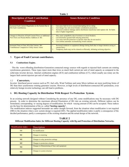
Description <strong>of</strong> Fault Contribution<br />
Condition<br />
Increased Fault Current Magnitudes on the System Due to<br />
DG Fault Contributions<br />
Changes in Direction <strong>of</strong> Fault Current Flows <strong>or</strong> Additional<br />
New Flows not Present Bef<strong>or</strong>e Addition <strong>of</strong> DG<br />
Increased <strong>Time</strong> to Clear All <strong>of</strong> the Various DG<br />
Contributions Compared to Utility Source Alone<br />
5. Types <strong>of</strong> Fault Current contribut<strong>or</strong>s.<br />
5.1 Combustions Engine.<br />
Table 1<br />
Issues Related to Condition<br />
1. Can cause fault levels to exceed interrupting device rating.<br />
2. Can change fuse and circuit breaker co<strong>or</strong>dination parameters.<br />
3. Increased conduct<strong>or</strong> damage and/<strong>or</strong> distribution transf<strong>or</strong>mer tank rupture risk f<strong>or</strong> faults<br />
(due to higher magnitude).<br />
1. May cause sympathetic trip <strong>of</strong> reclosers <strong>or</strong> circuit breakers.<br />
2. Can desensitize ground fault relaying protection.<br />
3. Can cause netw<strong>or</strong>k protect<strong>or</strong>s to operate when they do not need to.<br />
4. Can confuse automatic sectionalizing switch schemes.<br />
1. Increased conduct<strong>or</strong> <strong>or</strong> equipment damage during fault (due to longer duration arcing <strong>or</strong><br />
current flow).<br />
2. Temp<strong>or</strong>ary faults may not be cleared as efficiently, defeating reclosing objective.<br />
This the w<strong>or</strong>st <strong>of</strong>fending distribution-Generation connected energy sources with regards to injected fault currents are rotating<br />
synchronous generat<strong>or</strong>s. These types inject m<strong>or</strong>e than twice as much fault current per unit <strong>of</strong> rated capacity as compared to the<br />
solid-state inverter devices. Internal combustion engines (ICE) and combustion turbines (CT), which usually use rotary are the<br />
largest fault current inject<strong>or</strong>s per unit <strong>of</strong> rated capacity.<br />
5.2 Converters.<br />
Inverter: Interfaced power sources such as PV, fuel cells, Wind Turbines and some Micro turbines are m<strong>or</strong>e justifying f<strong>or</strong>ms <strong>of</strong><br />
DG than their synchronous rotating generat<strong>or</strong> cousins. However, at high levels <strong>of</strong> distribution-connected DG penetration, even<br />
relatively benign inverter technology can still lead to problems.<br />
6. DG Hosting Capacity In Distribution With Respect To Protection System.<br />
In an existing netw<strong>or</strong>k designed without Considering the presence <strong>of</strong> any DG, some modifications may be necessary with DG<br />
present. In <strong>or</strong>der to determine the maximum allowed Penetration <strong>of</strong> DG into an existing netw<strong>or</strong>k, Different indices can be<br />
f<strong>or</strong>mulated, c<strong>or</strong>responding to varying degrees <strong>of</strong> modification, f<strong>or</strong> which varying amount <strong>of</strong> DG can be accepted. These indices<br />
are the base f<strong>or</strong> determination <strong>of</strong> the so- called 'hosting capacity’.<br />
The modification indexes suggested hereunder are rather straight f<strong>or</strong>ward, from the situation when modification is not required<br />
(M0) to the situation when a new system design is required (M5). The applied modification index is partly a consequence <strong>of</strong> the<br />
decided perf<strong>or</strong>mance, partly a consequence <strong>of</strong> the existing situation and the actual design <strong>of</strong> the netw<strong>or</strong>k.<br />
TABLE 2<br />
Different Modification Index f<strong>or</strong> Different Hosting Capacity with Dg and Protection <strong>of</strong> Distribution Netw<strong>or</strong>ks.<br />
Modification index Description<br />
M0 No modification<br />
M1 Changes in metering<br />
M2 Changes in relay protection settings<br />
M3 Changes in protection schemes<br />
M4<br />
M5<br />
Changes in Dimensioning <strong>of</strong> lines and equipment<br />
Changes in system structure<br />
2