TruSpeed DC Manual - Tele-Traffic
TruSpeed DC Manual - Tele-Traffic
TruSpeed DC Manual - Tele-Traffic

Create successful ePaper yourself
Turn your PDF publications into a flip-book with our unique Google optimized e-Paper software.
Sensors<br />
The <strong>TruSpeed</strong> <strong>DC</strong> has two lenses on the front panel. The top lens transmits the infrared<br />
laser signals. The bottom lens receives the signals back from the target and feeds signal<br />
information to the internal circuitry.<br />
The internal circuitry consists of a laser range sensor and timing, analysis, computation,<br />
and display circuits. The <strong>TruSpeed</strong> <strong>DC</strong> determines distance through its laser range sensor,<br />
by measuring the time of flight of short pulses of infrared light. The <strong>TruSpeed</strong> <strong>DC</strong> has a<br />
broad spectrum of sensitivity, and can work with both reflective and non-reflective targets.<br />
The maximum measurement distance varies with target and environmental conditions.<br />
• The absolute maximum is about 750 metres for the United Kingdom model.<br />
LCD Screen<br />
The LCD Screen displays menu items, option indicators, error codes, and speed<br />
measurement results.<br />
Serial Port<br />
Your <strong>TruSpeed</strong> <strong>DC</strong> includes a serial port located on the rear panel. The serial port allows<br />
you to connect the instrument to a data collector or remote computer.<br />
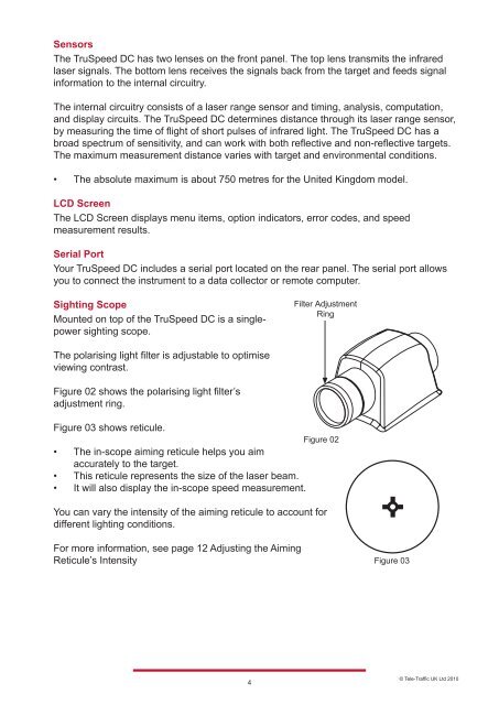
Sighting Scope<br />
Mounted on top of the <strong>TruSpeed</strong> <strong>DC</strong> is a singlepower<br />
sighting scope.<br />
The polarising light filter is adjustable to optimise<br />
viewing contrast.<br />
Figure 02 shows the polarising light filter’s<br />
adjustment ring.<br />
Figure 03 shows reticule.<br />
Figure 02<br />
• The in-scope aiming reticule helps you aim<br />
accurately to the target.<br />
• This reticule represents the size of the laser beam.<br />
• It will also display the in-scope speed measurement.<br />
You can vary the intensity of the aiming reticule to account for<br />
different lighting conditions.<br />
For more information, see page 12 Adjusting the Aiming<br />
Reticule’s Intensity<br />
4<br />
Filter Adjustment<br />
Ring<br />
Figure 03<br />
© <strong>Tele</strong>-<strong>Traffic</strong> UK Ltd 2010