LTI 20.20 UltraLyte 1000 Operations Manual - Tele-Traffic
LTI 20.20 UltraLyte 1000 Operations Manual - Tele-Traffic
LTI 20.20 UltraLyte 1000 Operations Manual - Tele-Traffic

You also want an ePaper? Increase the reach of your titles
YUMPU automatically turns print PDFs into web optimized ePapers that Google loves.
<strong>LTI</strong> <strong>20.20</strong> <strong>UltraLyte</strong> <strong>1000</strong><br />
<strong>Operations</strong> <strong>Manual</strong><br />
© <strong>Tele</strong>-<strong>Traffic</strong> UK Ltd 2006
T<br />
2S<br />
2<br />
2<br />
2<br />
2<br />
2<br />
3<br />
3<br />
3<br />
3<br />
4<br />
4<br />
6<br />
6<br />
7<br />
7<br />
7<br />
8<br />
9<br />
9<br />
10<br />
10<br />
11<br />
11<br />
12<br />
12<br />
13<br />
13<br />
13<br />
14<br />
15<br />
15<br />
17<br />
17<br />
17<br />
17<br />
18<br />
19<br />
19<br />
21<br />
21<br />
21<br />
21<br />
21<br />
21<br />
21<br />
21<br />
22<br />
22<br />
22<br />
22<br />
22<br />
23<br />
24<br />
25<br />
25<br />
Table of Contents<br />
Safety Precautions<br />
Section 1 – Getting Started<br />
Unpacking Your <strong>UltraLyte</strong> <strong>1000</strong><br />
<strong>UltraLyte</strong> <strong>1000</strong> Package<br />
Available Accessories<br />
About the <strong>UltraLyte</strong> <strong>1000</strong><br />
Sensors<br />
LCD Screen<br />
Serial Port Connector<br />
Sighting Scope<br />
Button Panels<br />
Fold-Away Shoulder Stock<br />
Attaching the Yoke<br />
Inserting the Batteries<br />
Powering ON the <strong>UltraLyte</strong> <strong>1000</strong><br />
Powering OFF the <strong>UltraLyte</strong> <strong>1000</strong><br />
Extending the display Segment Test<br />
Understanding the Display Indicators<br />
Miscellaneous Display Features<br />
Adjusting the Aiming Dot’s Intensity<br />
Viewing the Firmware Revision Number<br />
Restoring the Factory Defaults<br />
Listening to the <strong>UltraLyte</strong> <strong>1000</strong><br />
Understanding Error Conditions<br />
Section 2 – Speed Measurements<br />
Taking a Sample Measurement<br />
Choosing a Roadside Location<br />
Line of Sight<br />
The Cosine Effect<br />
Measuring a Moving Vehicle<br />
Jam Indicator<br />
Using the Weather Filter<br />
Section 3 – Instrument Tests<br />
Display Integrity Test<br />
Scope Alignment<br />
Scope Alignment Test<br />
Scope Alignment Procedure<br />
Instrument Confidence Check<br />
Fixed Distance Test<br />
Section 4 – Maintenance<br />
Operating Temperature<br />
Moisture and Dust Protection<br />
Shock Protection<br />
Cleaning and Storage<br />
Caring for the Scope<br />
Checking the Screen Display<br />
Resetting the Factory Default Settings<br />
Section 5 - Serial Data Interface<br />
Data Format<br />
Format Parameters<br />
Download Format<br />
Version ID requests<br />
Speed/Range Data Message Format<br />
Section 6 – Specifications<br />
Section 7 – Troubleshooting Tips<br />
Contact Details<br />
© <strong>Tele</strong>-<strong>Traffic</strong> UK Ltd 2006
Safety Precautions<br />
Avoid staring directly at the laser beam for prolonged periods.<br />
The <strong>UltraLyte</strong> <strong>1000</strong> is designed to meet IEC EN60825-1 standard and FDA eye safety requirements and is classified as eye-safe<br />
to Class 1 limits, which means that virtually no hazard is associated with directly viewing the laser output under normal conditions.<br />
As with any laser device, however, reasonable precautions should be taken in its operation. It is recommended that you avoid<br />
staring into the transmit aperture while firing the laser. The use of optical instruments with this product may increase eye hazard.<br />
Never attempt to view the sun through the scope.<br />
Looking at the sun through the scope may permanently damage your eyes.<br />
Never point the instrument directly at the sun.<br />
Exposing the lens system to direct sunlight, even for a brief period, may permanently damage the laser transmitter.<br />
Do not expose the instrument to extreme temperatures.<br />
o<br />
o<br />
<strong>UltraLyte</strong> <strong>1000</strong> components are rated for a temperature range of –30 C to +60 C. Do not expose the instrument to temperatures<br />
outside that range.<br />
Section 1 – Getting Started<br />
<strong>Tele</strong> <strong>Traffic</strong>’s <strong>UltraLyte</strong> <strong>1000</strong> is part of the <strong>UltraLyte</strong> family of handheld laser speed and ranging devices. Compared to the other<br />
<strong>UltraLyte</strong> models, the <strong>UltraLyte</strong> <strong>1000</strong>:<br />
• Has simplified menus and options.<br />
• Includes a built-in Weather Filter that is an alternate speed measuring mode. The Weather Filter is a simplified <strong>UltraLyte</strong><br />
gating option. This factory-defined gate ensures that targets are beyond the range where rain and snow can affect the laser’s<br />
ability to capture a speed reading.<br />
Other Features of the <strong>UltraLyte</strong> <strong>1000</strong> include:<br />
• Liquid Crystal Display (LCD) screen for instant access to measurements and options.<br />
• Serial output port for easy connection to a data collector or remote computer.<br />
• Fully adjustable, fold-away shoulder stock.<br />
• Sighting scope with in-scope red aiming dot and in-scope measurement display.<br />
• Two 3-button panels that provide quick and easy access to the instrument display.<br />
• Sounds and visual indicators that ensure confidence of positive target acquisition.<br />
Unpacking Your <strong>UltraLyte</strong> <strong>1000</strong><br />
When you receive your <strong>UltraLyte</strong> <strong>1000</strong>, check to make sure that you have received everything that you ordered, and that it all<br />
arrived undamaged.<br />
<strong>UltraLyte</strong> <strong>1000</strong> Package<br />
• <strong>UltraLyte</strong> <strong>1000</strong> instrument<br />
• Two C batteries<br />
• User’s manual<br />
• Carrying case<br />
Available Accessories<br />
You may have also ordered one or more of these optional accessories:<br />
• <strong>UltraLyte</strong> 2X Converter Upgrade<br />
• <strong>UltraLyte</strong> Battery Eliminator<br />
• Serial data cable (remote trigger optional)<br />
• Yoke (includes adapter for monopod/tripod mounting)<br />
• Monopod/Tripod<br />
2<br />
© <strong>Tele</strong>-<strong>Traffic</strong> UK Ltd 2006
About the <strong>UltraLyte</strong> <strong>1000</strong><br />
Figure 1 shows the <strong>UltraLyte</strong> <strong>1000</strong>’s front and rear panels.<br />
Sensors<br />
The <strong>UltraLyte</strong> <strong>1000</strong> has two lenses on the front panel. The top lens transmits the infrared laser signals. The bottom lens<br />
receives signals back from the target and feeds signal information to the internal circuitry.<br />
The internal circuitry consists of a laser range sensor and timing, analysis, computation and display circuits. The <strong>UltraLyte</strong><br />
<strong>1000</strong> determines distance through its laser range sensor, by measuring the time of flight of short pulses of infrared light. The<br />
<strong>UltraLyte</strong> <strong>1000</strong> has a broad spectrum of sensitivity and can work with both reflective and non-reflective targets. The maximum<br />
measurements distance varies with target and environment conditions. The absolute maximum is about <strong>1000</strong> meters.<br />
LCD Screen<br />
The LCD Screen displays menu items, option indicators, error codes and speed measurement results.<br />
Serial Port Connector<br />
The serial port connector allows you to connect the instrument to a data collector or remote computer. For more information<br />
about the Serial Data Interface, see page 22.<br />
Sighting Scope<br />
Mounted on top of the <strong>UltraLyte</strong> <strong>1000</strong> is a single-power sighting scope. The scope features:<br />
• Adjustable polarizing light filter to optimize viewing contrast.<br />
Figure 2 shows the polarizing light filter’s adjustment ring.<br />
• In-scope red aiming dot to help you aim accurately to the target.<br />
• In-scope measurement display. Figure 3 shows the In-scope aiming dot.<br />
You can vary the intensity of the red dot to account for<br />
different lighting conditions. For more information, see<br />
page 9.<br />
3<br />
Figure 2: Polarizing Light Filter<br />
87<br />
Figure 3: In-scope Aiming Dot<br />
© <strong>Tele</strong>-<strong>Traffic</strong> UK Ltd 2006
Button Panels<br />
The <strong>UltraLyte</strong> <strong>1000</strong> has two, 3-button panels; one on each side of the instrument. The buttons provide easy access to the<br />
instrument functions. Table 1 lists the buttons and the functions of each.<br />
Left Panel Right Panel<br />
Fold-Away Shoulder Stock<br />
Table 1. Button Names and Functions<br />
Button Function<br />
SPEED MODE<br />
Activates the instrument’s speed measurement mode.<br />
WEATHER FILTER<br />
Activates the instrument’s alternate speed measurement mode.<br />
SURVEY MODE<br />
The <strong>UltraLyte</strong> <strong>1000</strong> does not include the Survey Mode. This button serves no purpose.<br />
TEST OPTIONS<br />
Activates the instrument’s test mode.<br />
SCOPE BRIGHTNESS Varies the intensity of the in-scope red aiming dot.<br />
BACKLIGHT POWER OFF Press and hold for 2.5 seconds: Powers OFF the instrument.<br />
This manual simplifies button names to relate to current function instead of matching the instrument’s label.<br />
For example:<br />
Button Names According to the Label.<br />
Press the BACKLIGHT POWER OFF button.<br />
Button Names in this <strong>Manual</strong><br />
Press the BACKLIGHT button.<br />
-or-<br />
Press the POWER OFF button<br />
The shoulder stock is fully adjustable, and is designed for either left-handed or right-handed use.<br />
Unfolding the Stock for Left-Handed Use<br />
Refer to the instructions and figure 4 below to unfold the stock for left-handed use.<br />
1. Turn the tension knob counter-clockwise to loosen the stock.<br />
2. Rotate the stock 180 degrees.<br />
3. Turn the tension knob clockwise to retighten the stock.<br />
Figure 4: Unfolding the Shoulder Stock for Left-Handed Use<br />
4<br />
© <strong>Tele</strong>-<strong>Traffic</strong> UK Ltd 2006
Unfolding the Stock for Right-Handed Use<br />
Refer to the instructions and Figure 5 below to unfold the stock for right-handed use.<br />
1. Hold the instrument firmly, and press down on the retaining plate with enough force to disengage the plate from the stock’s<br />
peg.<br />
2. Pull the stock away from the body of the instrument and release the plate.<br />
3. Rotate the stock to the right until the retainer peg re-engages. You should hear a loud click when the peg re-engages.<br />
Adjusting the Length and Angle<br />
Refer to the instructions and Figure 6 below to adjust the stock’s length and angle.<br />
Length:<br />
1. Loosen the tension knob.<br />
2. Slide the stock back and forth to desired position.<br />
3. Retighten the tension knob.<br />
Angle:<br />
1. Loosen the tension knob slightly.<br />
2. Move the stock up or down. Usually, it is best if the stock is at a slight downward angle.<br />
Refolding the Stock<br />
Refer to the instructions below to refold the stock.<br />
Figure 5: Unfolding the Shoulder Stock for Right-Handed Use<br />
Figure 6: Adjusting the Shoulder Stock<br />
1. Extend the stock to its full length.<br />
2. Reverse the procedure that you used to open it (see above).<br />
Although the stock can be folded on either side, the <strong>UltraLyte</strong> <strong>1000</strong> only fits in its carry case when stock is fully extended<br />
and folded on the left side of the instrument.<br />
5<br />
© <strong>Tele</strong>-<strong>Traffic</strong> UK Ltd 2006
Attaching the Yoke<br />
The <strong>UltraLyte</strong> Yoke is an available accessory that allows you to mount the <strong>UltraLyte</strong> <strong>1000</strong> on a monopod or tripod. Refer to the<br />
instructions and Figure 7 below to attach the yoke to the <strong>UltraLyte</strong> <strong>1000</strong>.<br />
The yoke can be mounted on either side of the instrument. When the yoke is mounted on the left side, the entire<br />
assembly fits into the padded carrying case.<br />
1. Screw the mounting bracket and yoke adaptor into the mounting holes on the side of the instrument base.<br />
2. Fit the yoke onto the mounting bracket.<br />
3. Tighten the knob.<br />
Inserting the Batteries<br />
Figure 7: Attaching the Yoke Adaptor and Yoke<br />
Two C batteries are required to power the <strong>UltraLyte</strong> <strong>1000</strong>. Refer to the instructions and Figure 8 below when inserting the<br />
batteries<br />
1. Remove the battery compartment cap by twisting counter clockwise.<br />
2. Insert the two batteries, positive end first, into the battery compartment in the instrument handle.<br />
3. Replace the cap.<br />
4. Twist the cap clockwise until it stops and its secure. Be careful to not over-tighten the cap.<br />
Figure 8: Inserting the Batteries<br />
6<br />
© <strong>Tele</strong>-<strong>Traffic</strong> UK Ltd 2006
Battery Voltage Level<br />
The <strong>UltraLyte</strong> <strong>1000</strong> continuously monitors it’s power source. <strong>Tele</strong>-<strong>Traffic</strong> UK has defined an acceptable battery voltage range<br />
to ensure that the instrument has sufficient voltage to guarantee correct operation.<br />
•<br />
•<br />
The “BATT” display feature flashes on the screen if the battery voltage drops to the upper end of the acceptable battery<br />
voltage range. It continues to flash as long as battery voltage is within the acceptable range. You should replace the batteries<br />
as soon as possible. The display backlight is not accessible during low battery situations.<br />
The “BATT” indicator stops flashing, and stays displayed on the screen if the battery voltage level drops below the acceptable<br />
battery voltage range. If you fail to replace the batteries, the button panels will lock out.<br />
Powering ON the <strong>UltraLyte</strong> <strong>1000</strong><br />
To power ON the <strong>UltraLyte</strong> <strong>1000</strong>:<br />
1. Press the TRIGGER. Briefly, the screen display should look like Figure 9 below, and then the display will change to the<br />
Speed Measurement Screen. See figure 15 on page 12.<br />
Powering OFF the <strong>UltraLyte</strong> <strong>1000</strong><br />
To power OFF the <strong>UltraLyte</strong> <strong>1000</strong>:<br />
1. Press and hold the POWER OFF button for approximately 2.5 seconds.<br />
Extending the Display Segment Test<br />
Figure 9: LCD Display Segments<br />
To help save its batteries, the <strong>UltraLyte</strong> <strong>1000</strong> has a factory-defined power OFF interval. The instrument will automatically<br />
power OFF if there is no activity for a period of 15 minutes. Instrument activity includes any button presses or serial<br />
communication.<br />
Extending the Display Segment Test lets you confirm that all display indicators are working. Refer to the instructions below to<br />
extend the display segment test.<br />
1. With the <strong>UltraLyte</strong> <strong>1000</strong> powered OFF, press and hold the TRIGGER.<br />
2. Refer to Figure 9 (above) to ensure that all of the display segments are showing on your <strong>UltraLyte</strong> <strong>1000</strong>.<br />
3. Release the TRIGGER. Upon release of the TRIGGER, the display will change to the Speed Measurement Screen. See<br />
Figure 15 on page 12.<br />
If you need assistance, contact <strong>Tele</strong>-<strong>Traffic</strong> UK. See page 25 for <strong>Tele</strong> <strong>Traffic</strong> UK contact information.<br />
7<br />
© <strong>Tele</strong>-<strong>Traffic</strong> UK Ltd 2006
Understanding the Display Indicators<br />
Table 2 lists the display indictors and the function of each. The indictors appear in order of location on the display, from left to<br />
right starting in the upper left corner. See Figure 9 on page 7.<br />
Display Indicator<br />
MENU<br />
LASER<br />
BATT<br />
MPH<br />
KmH<br />
CmS<br />
JAM<br />
GSL<br />
TOD<br />
CONT<br />
TEST<br />
DBC<br />
DELTA<br />
MUTE<br />
F M<br />
S<br />
D G<br />
V<br />
Function<br />
Display Backlight<br />
Options Menu<br />
Laser Fire<br />
Battery<br />
Upper Display<br />
Speed Units<br />
Jam Detection<br />
Gate<br />
Short<br />
Long<br />
Time Over Distance<br />
Continuous Mode<br />
Speed Mode<br />
Survey Mode<br />
Test Mode<br />
Distance Between Cars<br />
Distance Difference<br />
Mute (silent) Mode<br />
Survey Icon<br />
Lower Display<br />
Distances Units<br />
Time Units<br />
Inclination Units<br />
Power Units<br />
Table 2. Display Indictors<br />
Visible – The LED backlight is ON.<br />
Not Visible - The LED backlight is OFF.<br />
This feature is not available on the <strong>UltraLyte</strong> <strong>1000</strong>.<br />
The instrument’s laser is firing.<br />
Flashing – Battery voltage is low.<br />
Steady – Battery voltage is too low. Power OFF the instrument.<br />
Not Visible – Battery voltage is within the factory defined acceptable<br />
range.<br />
Provides access to speed measurements and messages.<br />
MPH – Miles per Hour<br />
KmH - This feature is not available on the <strong>UltraLyte</strong> <strong>1000</strong>.<br />
CmS - This feature is not available on the <strong>UltraLyte</strong> <strong>1000</strong>.<br />
Indicates Jamming Signal.<br />
Explanation<br />
When the instrument’s Weather Filter is active, the “GS” indictor<br />
is displayed. This is an alternate speed measurement mode that<br />
includes a factory-defined gate setting.<br />
This feature is not available on the <strong>UltraLyte</strong> <strong>1000</strong>.<br />
This feature is not available on the <strong>UltraLyte</strong> <strong>1000</strong>.<br />
The instrument’s Speed Mode is active.<br />
This feature is not available on the <strong>UltraLyte</strong> <strong>1000</strong>.<br />
The instrument’s Test Mode is active.<br />
This feature is not available on the <strong>UltraLyte</strong> <strong>1000</strong>.<br />
This feature is not available on the <strong>UltraLyte</strong> <strong>1000</strong>.<br />
This feature is not available on the <strong>UltraLyte</strong> <strong>1000</strong>.<br />
This feature is not available on the <strong>UltraLyte</strong> <strong>1000</strong>.<br />
Provides access to range measurements and messages.<br />
F - This feature is not available on the <strong>UltraLyte</strong> <strong>1000</strong>.<br />
M – Meters<br />
This feature is not available on the <strong>UltraLyte</strong> <strong>1000</strong>.<br />
This feature is not available on the <strong>UltraLyte</strong> <strong>1000</strong>.<br />
This feature is not available on the <strong>UltraLyte</strong> <strong>1000</strong>.<br />
8<br />
© <strong>Tele</strong>-<strong>Traffic</strong> UK Ltd 2006
Miscellaneous Display Features<br />
Table 3 lists the miscellaneous display features that are not part of the Display Segment Test:<br />
Display<br />
Feature<br />
br xx<br />
CLEAr<br />
dEF<br />
Exx<br />
FiLtEr<br />
Adjusting the Aiming Dot’s Intensity<br />
tt<br />
Table 3. Miscellaneous Display Features<br />
Explanation<br />
The in-scope red aiming dot’s intensity setting.<br />
When restoring factory defaults, indicates that the task<br />
was completed.<br />
When the Speed Mode is active, indicates that the<br />
Weather Filter is OFF.<br />
The instrument is restoring the factory defaults.<br />
Error Code. An error condition has occurred during a<br />
measurement or in the system hardware.<br />
Appears at the bottom of the screen when the instrument’s<br />
Weather Filter is toggled ON.<br />
The instrument’s test tone is active. Used during the<br />
Scope Alignment Test and Procedure.<br />
Refer to<br />
Pages<br />
The in-scope red aiming dot has eight intensity settings from OFF (00) to BRIGHT (07). Refer to the instructions and Figure 10<br />
below to adjust the red aiming dot’s intensity.<br />
1. Press the SCOPE BRIGHTNESS button. The display should look similar to Figure 10. The current setting is whatever “br<br />
xx” is displayed. The factory default setting is “br 05” as shown in the figure.<br />
Figure 10: Aiming Dot Intensity Setting<br />
2. Press the SCOPE BRIGHTNESS button until the setting is correct. It’s easy to get the correct setting if you look through the<br />
scope while making the adjustment.<br />
3. Press the TRIGGER to the measuring mode that was most recently active . Otherwise, press the button that corresponds<br />
with whatever it is that you want to do next. For more information, see Table 2 on page 8.<br />
• Each time you press the SCOPE BRIGHTNESS button, the “br xx” value increases by 1.<br />
• If you press the SCOPE BRIGHTNESS button while “br 07” is displayed, you will see “br 00” next.<br />
• Powering OFF the instrument does not change this setting. The next time the instrument is powered ON, the setting<br />
will be the same.<br />
9<br />
9<br />
10<br />
12<br />
10<br />
11<br />
15<br />
17-18<br />
© <strong>Tele</strong>-<strong>Traffic</strong> UK Ltd 2006
Viewing the Firmware Revision Number<br />
Firmware is the internal software that controls how the <strong>UltraLyte</strong> <strong>1000</strong> works. The firmware revision number provides<br />
manufacturing information about your <strong>UltraLyte</strong> <strong>1000</strong>. It can only be viewed at power ON. Refer to the instructions below to<br />
view the firmware revision number.<br />
1. With the <strong>UltraLyte</strong> <strong>1000</strong> powered OFF, press and hold the TRIGGER.<br />
2. Press the SURVEY MODE button. The display should look similar to Figure 11.<br />
3. Release the SURVEY MODE button.<br />
In this example:<br />
• 100 is the model number.<br />
• 3.03 is the software revision number.<br />
• MPH (miles per hour) is the factory default speed unit.<br />
• M (metres) is the factory default range unit.<br />
• D (degrees) is the factory default angular unit.<br />
4. Release the TRIGGER. Display will change to the Speed Measurement Screen, see figure 15 on page 12.<br />
For further reference, note the firmware revision number here:<br />
Restoring the Factory Defaults<br />
Figure 11: Mode and Firmware Revision<br />
The <strong>UltraLyte</strong> <strong>1000</strong> has one user-selectable option – the in-scope aiming dot’s intensity. Although, you may never need to, you<br />
can restore the instrument’s factory settings. Refer to the instructions and Figures 12 and 13 below to restore the factory default<br />
for the in-scope aiming dot’s intensity.<br />
1. With the <strong>UltraLyte</strong> <strong>1000</strong> powered OFF, press and hold the TRIGGER.<br />
2. Press and hold the BACKLIGHT button. The display should look like<br />
Figure 12.<br />
3. Continue to hold the TRIGGER and the BACKLIGHT button until the<br />
CLEAR indicator is displayed as Figure 13 shows.<br />
4. Release the TRIGGER and the BACKLIGHT button. The display will<br />
change to the Speed Measurement Screen, see Figure 15 on page 12.<br />
10<br />
Figure 12: Restoring the Factory Defaults<br />
Figure 13: Factory Defaults Restored<br />
© <strong>Tele</strong>-<strong>Traffic</strong> UK Ltd 2006
Listening to the <strong>UltraLyte</strong> <strong>1000</strong><br />
The <strong>UltraLyte</strong> <strong>1000</strong> emits a variety of beeps and tones during use. The sounds vary and depend on what the instrument is<br />
doing. With experience, you will be able to tell what is happening simply by listening. Table 4 lists and explains each of the<br />
sounds.<br />
Error Codes<br />
Table 5 lists and explains each of the possible error codes.<br />
Table 4. Sounds and What They Mean<br />
Sound Explanation<br />
High-Pitched Beep<br />
The instrument successfully completed the intended speed measurement.<br />
Double High-Pitched Beep At power ON.<br />
Single Low-Pitched Beep The instrument was not able to take the intended measurement due to an error.<br />
An error code is displayed to indicate the nature of the error.<br />
Low-Pitched Growl<br />
The instrument is attempting to lock onto a target.<br />
High-Pitched Oscillating Ring Jam tone. The instrument’s laser return sensor is being overwhelmed by light.<br />
Understanding Error Conditions<br />
Error conditions can occur in a measurement or in the system<br />
hardware. To make sure that you do not get an erroneous speed<br />
reading, the <strong>UltraLyte</strong> <strong>1000</strong> monitors both the system hardware and<br />
the measurement. When the instrument detects an error condition, it<br />
displays an error code instead of a measurement.<br />
Error codes are in the form “Exx”, where “xx” is an error code number.<br />
Figure 14 shows an E03 error code, Measurement error – unstable<br />
targeting.<br />
Table 5. Error Codes and What They Mean<br />
Code Explanation<br />
doF<br />
Display overflow. The measurement exceeds the display capacity. It is possible to<br />
receive a doF message in the scope and still have a valid measurement display<br />
on the screen.<br />
E01<br />
Measurement error – target never acquired. The target was out of range or was<br />
too close.<br />
E02<br />
Measurement error – insufficient data. The instrument’s view was obstructed or<br />
the target moved out of range.<br />
E03<br />
Measurement error – unstable targeting. Caused by poor aiming or by panning<br />
off the target.<br />
Measurement error – low level of interference from a light source such as a<br />
headlight or a laser jamming device.<br />
E07<br />
Jam Detect – high level of interference from a light source such as a headlight or<br />
laser jamming device.<br />
E52<br />
Temperature too cold. Stop operation.<br />
E53<br />
Temperature too hot. Stop operation.<br />
E54 E61<br />
Calibration or memory checksum failure. If the error persists, contact <strong>Tele</strong>-<strong>Traffic</strong><br />
E55 E62<br />
UK Ltd. See page 25 for <strong>Tele</strong>-<strong>Traffic</strong> UK contact information.<br />
E56<br />
E60<br />
E63<br />
11<br />
Figure 14: Sample Error Code Display<br />
© <strong>Tele</strong>-<strong>Traffic</strong> UK Ltd 2006
RFI Considerations<br />
The <strong>UltraLyte</strong> <strong>1000</strong> does not display a specific error message indicating the presence of radio frequency interference (RFI). The<br />
instrument’s electronics have been designed for optimum RFI immunity.<br />
If RFI is present, the instrument displays an error code. The exact code depends on the level and nature of the RFI.<br />
Section 2 – Speed Measurements<br />
When you power ON the <strong>UltraLyte</strong> <strong>1000</strong>, the screen display should look similar to Figure 15.<br />
Taking a Sample Measurement<br />
Figure 15: Initial Speed Measurement Screen<br />
Refer to the instructions below to take a sample speed measurement.<br />
1. Ensure that the <strong>UltraLyte</strong> <strong>1000</strong> is powered ON and that the Speed Mode is active.<br />
2. Use the sighting scope to aim the instrument to a convenient target – an interior wall will do.<br />
3. Fire the laser:<br />
• Press and hold the TRIGGER. The laser will fire after a short delay (about one-half of a second).<br />
-or-<br />
• Press the TRIGGER twice. The 1st press turns on the in-scope red aiming dot. The 2nd press takes the measurement.<br />
4. Continue to press the TRIGGER and keep the instrument sighted on the target:<br />
• A low-pitched growl means that the instrument is attempting to lock onto the target.<br />
• A low-pitched beep means that a measurement error occurred. An error code will be displayed.<br />
• A high-pitched beep means that a speed was captured. The measured speed will be displayed on the LCD screen<br />
and will be projected on the scope, just below the aiming dot.<br />
After you release the TRIGGER the instrument will display the speed reading and the distance at which it was captured or an<br />
error code. When the speed reading is displayed, the display screen will look similar to Figure 16.<br />
Figure 16: Sample Speed Measurement – Wall<br />
12<br />
© <strong>Tele</strong>-<strong>Traffic</strong> UK Ltd 2006
Choosing a Roadside Location<br />
When choosing a spot on the side of the road for measuring moving vehicles, you will need to consider the following:<br />
• Do you have a clear line of sight?<br />
• What is the approximate angle between the instrument’s position and the target vehicle’s direction of travel?<br />
• What is the approximate distance to the target vehicles?<br />
• How is the weather? Will you need to use the Weather Filter?<br />
Line of Sight<br />
Ideally, you should have a clear line of sight to the target vehicle. However, if there is a break in the beam, the instrument may<br />
be able to accumulate enough data to capture the target vehicle’s speed.<br />
• If there is a momentary break in the beam, the instrument will accumulate data and may be able to capture the target<br />
vehicle’s speed. The instrument will display an error code if it cannot capture the target vehicle’s speed.<br />
• If there is an extended break in the beam, the instrument will display an error code.<br />
The Cosine Effect<br />
If the target vehicle is moving directly toward or away from you, the speed measured by the <strong>UltraLyte</strong> <strong>1000</strong> is identical to<br />
the vehicle’s true speed. However, the instrument is usually set up on the side of the road for safety. This results in an angle<br />
between the instrument’s position and the target vehicle’s direction of travel. When the angle is significant, the measured speed<br />
is less than the target’s true speed. The phenomenon is known as the cosine effect. Cosine is the trigonometric function that<br />
relates to this phenomenon.<br />
The difference between the measured speed and the true speed depends upon the angle between the instrument’s ideal<br />
position – the position where targets would be moving in direct line with the instrument – and it’s actual position.<br />
• The larger the angle, the lower the measured speed.<br />
• The effect always works to the motorist’s advantage.<br />
• Loosely speaking, the cosine effect is not significant as long as the angle remains small.<br />
Table 6 shows this effect.<br />
Table 6. Measured Speed by Angle: The Cosine Effect<br />
Angle<br />
(degrees)<br />
30 mph<br />
True Speed<br />
40 mph 50 mph 60 mph 70 mph<br />
Measured Speed (mph)<br />
0 30.00 40.00 50.00 60.00 70.00<br />
1 29.99 39.99 49.99 59.99 69.99<br />
3 29.96 39.94 49.93 59.92 69.90<br />
5 29.89 39.85 49.81 59.77 69.73<br />
10 29.54 39.39 49.24 59.09 68.94<br />
15 28.98 38.64 48.30 57.94 67.61<br />
20 28.19 37.59 46.99 56.38 65.78<br />
45 21.21 28.28 35.36 42.43 49.50<br />
90 00.00 00.00 00.00 00.00 00.00<br />
The cosine effect decreases as the range to the target vehicle increases.<br />
• At the maximum range of the instrument, the vehicle is so far away that the angle between it and the instrument is very<br />
small indeed. The instrument’s perception of the target’s speed is identical to its true speed.<br />
• As the vehicle approaches, the angle increases until it becomes large enough to affect the measurement.<br />
To minimize the cosine effect, keep the angle small. Set up the instrument as close to the road as possible without<br />
creating safety risks and target down the road at ranges sufficient to keep the angular difference small.<br />
13<br />
© <strong>Tele</strong>-<strong>Traffic</strong> UK Ltd 2006
Table 7 shows acceptable parameters for minimizing the cosine effect. The chart indicates the percentage of true speed<br />
measured, given the distance from the roadway and the distance from the target vehicle. To find a target’s measured speed,<br />
multiply the true speed by the number in the chart<br />
Distance off the<br />
Roadway<br />
(meters)<br />
Table 7. Percentage of True Speed Measured<br />
The diagonal created by the boldface numbers indicates the boundary between acceptable and unacceptable parameters.<br />
• Numbers above the diagonal are acceptable margins of error.<br />
• Numbers below the diagonal are unacceptable margins of error.<br />
Remember that the cosine effect is always in the motorist’s favour.<br />
Measuring a Moving Vehicle<br />
Range to Target Vehicle<br />
30 m 100 m 150 m 300 m 600 m<br />
fraction of true speeed that will be measured<br />
3 .9950 .9995 .9998 .9999 1.0000<br />
10 .9682 .9950 .9987 .9997 .9999<br />
15 .8660 .9886 .9950 .9987 .9997<br />
30 .0000 .9539 .9789 .9950 .9987<br />
60 .0000 .7999 .9165 .9798 .9950<br />
As a general rule, do not exceed 1 meter off the road for every 10 meters shooting down range to the targets. If target<br />
vehicles will be 150 meters down the road, set up no more that 15 meters off the road.<br />
Refer to the instructions below to use the <strong>UltraLyte</strong> <strong>1000</strong> to measure the speed of a moving vehicle.<br />
1. Ensure that the <strong>UltraLyte</strong> <strong>1000</strong> is powered ON and that the Speed Mode is active.<br />
2. Use the sighting scope to aim the instrument at the target’s vehicle’s license plate area and press the TRIGGER.<br />
3. Continue to press the TRIGGER and keep the instrument sighted on the target.<br />
• A low-pitched growl means that the instrument is attempting to lock onto the target<br />
• A low-pitched beep means that a measurement error occurred. An error code will be displayed.<br />
• A high-pitched beep means that a speed was captured. The measured speed will be displayed on the LCD screen and will<br />
be projected on the scope, just below the aiming dot.<br />
While the instrument is attempting to lock onto the target , as long as the TRIGGER is kept pressed, it will retry the speed<br />
measurement.<br />
• Depending upon it’s configuration, the instrument will try to 10 times or more. Information is accumulated until it gets a<br />
good measurement or generates an error code.<br />
• Consequently, it is very important that the aiming point on the target remain constant for the entire measurement time. If<br />
you move the instrument off the aiming point, it will generate an error code instead of capturing a speed reading.<br />
After you release the TRIGGER the instrument will display the speed reading and the distance at which it was captured or an<br />
error code. When the speed reading is displayed, the display screen will look similar to Figure 17.<br />
Figure 17: Sample Speed Measurement – Departing Vehicle<br />
• The speed displays as a negative number if the target was going away from you when it was measured.<br />
• The speed displays as a positive number if the target was approaching you when it was measured.<br />
14<br />
© <strong>Tele</strong>-<strong>Traffic</strong> UK Ltd 2006
Jam Indicator<br />
The JAM display indicator (page 8) on the back panel screen may blink during a measurement and may be accompanied by the<br />
jam tone (page 11). This indicates that the instrument is being flooded by light and is having difficulty detecting its own signal.<br />
There are two possible situations:<br />
• You are targeting a strong light source such as headlights.<br />
-or-<br />
• A targeted vehicle is employing a laser jamming device.<br />
Regardless of the level of interference, you will never get an erroneous speed reading.<br />
• At a low level of interference, a speed may be captured or an E03 error code may be displayed.<br />
• At a high level of interference, an E07 error code will be displayed.<br />
Using the Weather Filter<br />
Moisture is reflective. Weather such as rain, snow, or fog can make if difficult for the laser to receive signals back from the<br />
target. This is especially true when you are trying to capture speeds at a close range. The <strong>UltraLyte</strong><strong>1000</strong> includes a built-in<br />
Weather Filter that is an alternate speed measurement mode. When the Weather Filter is active, the factory-defined gate<br />
setting increases the instrument’s minimum range from 20 meters to 61 meters. Increasing the minimum range ensures that the<br />
laser only acquires targets beyond the range where weather affects the laser’s ability to capture a speed reading.<br />
When the Weather Filter is active:<br />
• The “SPEED” indictor is displayed.<br />
• The “GS” indictor appears on the screen and word “FiLtEr” appears at the bottom of the display screen until it is overwritten<br />
by the distance to the target vehicle when a speed measurement is completed.<br />
• Targets must be a distance greater than 61 meters.<br />
• The instrument’s maximum range is not changed.<br />
• Other than the above items, the <strong>UltraLyte</strong> <strong>1000</strong> operates the same as when the Speed Mode is active and the Weather<br />
Filter is OFF (see page 12).<br />
Refer to the instructions and Figure 18 below to activate the Weather Filter.<br />
1. Ensure that the <strong>UltraLyte</strong> <strong>1000</strong> is powered ON.<br />
2. Press the WEATHER FILTER button. The display should look similar to Figure 18.<br />
Figure 18: Initial Screen When the Weather Filter is Active<br />
3. Aim the instrument at the target vehicle’s license plate area and press the TRIGGER. A low-pitched growl begins, indicating<br />
the instrument is trying to acquire a lock on the target.<br />
4. Continue to press the TRIGGER and keep the instrument sighted on the target.<br />
• A low-pitched growl means that the instrument is attempting to lock onto the target. A low-pitched beep means that a<br />
measurement error occurred. An error code will be displayed.<br />
• A high-pitched beep means that a speed was captured. As long as you hold the TRIGGER, the instrument will continue to<br />
take speed measurements. The measured speed will be displayed on the LCD screen and will be projected on the scope,<br />
just below the aiming dot.<br />
While the instrument is attempting to lock onto the target, as long as the TRIGGER is kept pressed, it will retry the speed<br />
measurement.<br />
• Depending upon its configuration, the instrument will try up to 10 times or more. Information is accumulated until it gets a good<br />
measurement or generates an error code.<br />
• Consequently, it is very important that the aiming point on the target remain constant for the entire measurement time. If<br />
you move the instrument off the aiming point, it will generate an error code instead of capturing a speed reading.<br />
15<br />
© <strong>Tele</strong>-<strong>Traffic</strong> UK Ltd 2006
After you release the TRIGGER the instrument will display the most recent speed reading and the distance at which it was<br />
captured or an error code. When the most recent speed reading is displayed, the display screen will look similar to Figure 19.<br />
Figure 19: Sample Speed Measurement – Weather Filter ON<br />
When the Weather Filter is activated, the word “FiLtEr” appears at the bottom of the display screen. Once a successful<br />
speed measurement is completed, the distance measurement overwrites this part of the display. The “GS” display<br />
feature appears on the screen until the Weather Filter is no longer active.<br />
16<br />
© <strong>Tele</strong>-<strong>Traffic</strong> UK Ltd 2006
Section 3 – Instrument Tests<br />
There are three tests that allow you to verify the <strong>UltraLyte</strong> <strong>1000</strong>’s mechanics. These tests include:<br />
• Display Integrity Test<br />
• Scope Alignment Test<br />
• Fixed Distance Test<br />
Display Integrity Test<br />
The Display Integrity Test allows you to verify that all display segments are operating. <strong>Tele</strong>-<strong>Traffic</strong> UK suggests that you do this<br />
test periodically. Refer to the instructions and Figure 23 below to test the display integrity.<br />
1. Ensure that the <strong>UltraLyte</strong> <strong>1000</strong> is powered ON.<br />
2. Press the TEST OPTIONS button. The display should look like Figure 20.<br />
3. Compare the instrument’s display to the figure above. If any segment fails to display, contact <strong>Tele</strong>-<strong>Traffic</strong> UK Ltd, to arrange<br />
for repair. See page 25 for the <strong>Tele</strong>-<strong>Traffic</strong> UK contact information.<br />
Scope Alignment<br />
The scope alignment is set at the factory when the instrument is shipped. A heavy blow is the only reason that the scope might<br />
ever go out of alignment. This section includes the Scope Alignment Test and the Scope Alignment Procedure. <strong>Tele</strong>-<strong>Traffic</strong> UK<br />
suggests that you do this test periodically. The scope Alignment Procedure will only be necessary if the Scope Alignment Test<br />
shows that the scope is out of alignment.<br />
Scope Alignment Test<br />
Figure 20: Display Integrity Test<br />
You may also test the display integrity at power ON, by holding the TRIGGER (see page 7).<br />
This test uses sound to indicate when the scope is on-target. Refer to the instructions below to do the Scope Alignment Test.<br />
1. Select a target. Choose a prominent target with well-defined horizontal and vertical edges. The target’s reflective qualities<br />
and distance should be such that you can clearly hear a change in pitch of the test tone as you pan the instrument over<br />
the edges of the target. A telephone pole is an excellent choice. Make sure there is nothing behind the target that the<br />
instrument might detect, so you know without a doubt that any change in pitch is due strictly to the target.<br />
2. Ensure that the <strong>UltraLyte</strong> <strong>1000</strong> is powered ON.<br />
3. Press the TEST OPTIONS button twice to activate the Test Tone display screen. It should look like Figure 21.<br />
Figure 21: Test Tone Display Screen<br />
17<br />
© <strong>Tele</strong>-<strong>Traffic</strong> UK Ltd 2006
4. Scan the target. Press and hold the TRIGGER while panning the instrument across the target. The tone changes pitch<br />
when the instrument acquires the target. The highest-pitch – the on-target tone – should occur when the scope’s red<br />
aiming dot is centered on the target. Scan the target both horizontally and vertically.<br />
• If the frequency drops off at equal distances from the center of the aiming dot, the instrument needs no adjustment.<br />
• Otherwise, continue with the Alignment Procedure.<br />
• When checking vertical alignment to a close target, be aware of the offset between the center of the scope and the<br />
center of the transmit lens, which is 2 inches.<br />
• If you need assistance, contact <strong>Tele</strong>-<strong>Traffic</strong> UK. See page 25 for the <strong>Tele</strong>-<strong>Traffic</strong> UK contact information.<br />
Scope Alignment Procedure<br />
The point of this procedure is to align the laser’s point of impact with the in-scope red aiming dot, using sound to indicate when<br />
the scope is on-target. To align the scope properly, you will need:<br />
• Two metric Allen wrenches to expose and turn the scope adjustment screws. One 2.5 mm and one 1.5 mm.<br />
• A target at which to aim the instrument.<br />
• A highly stable base for the instrument. A tripod is recommended.<br />
Selecting a Target<br />
The target that you choose is critical to the success of the alignment procedure. The target should be reflective and large<br />
enough that you can see if from a distance, but small enough to be accurate indicator of where the laser beam is hitting.<br />
• A bicycle reflector at lease 8 cm in diameter is recommended.<br />
• The target should be at least 200 meters from the instrument. It should be silhouetted against the sky, with no other<br />
targets in the area. That’s so you can be certain of the general area that the laser is hitting.<br />
Refer to the instructions below to do the Scope Alignment Procedure.<br />
1. Steady the instrument on a steady base.<br />
2. Expose the adjustment screws. Using a 2.5 mm Allen wrench, remove the cover screws as shown in Figure 22.<br />
Figure 22: Scope Adjustment Screws<br />
Each cover screw assembly includes a small plastic washer. It is imperative that you not lose the washers. Failing to<br />
replace them renders the scope at risk to water damage.<br />
3. Ensure that the <strong>UltraLyte</strong> <strong>1000</strong> is powered ON.<br />
4. Press the TEST OPTIONS button twice to active the Test Tone display screen. It should look like Figure 21 on page 17.<br />
5. Select a target (see above).<br />
6. Scan the target. Press and hold the TRIGGER while panning the instrument across the target. When the tone achieves its<br />
highest pitch, the laser light beam is hitting the target.<br />
18<br />
© <strong>Tele</strong>-<strong>Traffic</strong> UK Ltd 2006
7. Adjust the scope by using a 1.5 mm Allen wrench to turn the adjustment screws. Adjust the position of the scope aiming<br />
dot, as shown in Figure 23.<br />
8. Check the alignment one last time. If the instrument does not pass, repeat the Alignment Procedure (steps 1-7 above).<br />
9. Replace the plastic washers and cover screws when the instrument passes the alignment test.<br />
Instrument Confidence Check<br />
You can verify the measurement accuracy of a Lidar instrument by measuring the speed of an object travelling at a known<br />
speed, but this is seldom practical. The nature of Lidar is such that it cannot be tricked by a vibrating object, such as a tuning<br />
fork, into displaying a velocity. For these reasons, <strong>Tele</strong>-<strong>Traffic</strong> UK designed the Fixed Distance Test. <strong>Tele</strong>-<strong>Traffic</strong> UK suggests<br />
that you do the Fixed Distance Test each time the instrument is taken on duty.<br />
The Fixed Distance Test verifies the accuracy of the two key elements of Lidar speed measurement:<br />
• Precise time measurements<br />
• Ability to make mathematical calculations<br />
When setting up an area for this test, <strong>Tele</strong>-<strong>Traffic</strong> UK recommends:<br />
• Permanently installing the test area in a convenient location. The test area must establish a permanent, known<br />
distance between a shooting mark and a target.<br />
• Using a metal tape to measure the distance, this will ensure that the measurement is accurate.<br />
Other considerations:<br />
Figure 23: Adjusting the Scope<br />
If you need assistance, contact <strong>Tele</strong>-<strong>Traffic</strong> UK. Seepage 25 for the <strong>Tele</strong>-<strong>Traffic</strong> UK contact information.<br />
• The shooting mark is where the operator stands to do the test and can be “X” painted on the pavement.<br />
• A target can be any flat, permanent structure – a sign or wall, for example – painted with a bull’s eye or another aiming<br />
point.<br />
• The shooting mark and the target(s) must form a straight line.<br />
• The distance specified is horizontal distance. Horizontal distance is measured along a straight, level path from the shooting<br />
mark to the center of the aiming point.<br />
• The manner in which you stand and hold the instrument both affect the test measurements. For exact readings, carefully<br />
hold the instrument so it is directly over the middle of the X.<br />
Fixed Distance Test<br />
The Fixed Distance Test requires one target. <strong>Tele</strong>-<strong>Traffic</strong> UK<br />
recommends that the target can be any distance from the shooting<br />
mark between the minimum and maximum operating capabilities of<br />
the device. See Figure 24. If there is not enough space available,<br />
that specific distance is not crucial. However, the distance between<br />
the target and the shooting mark must be a multiple of 1 meter; not<br />
a fraction of a meter.<br />
19<br />
Figure 23: Adjusting the Scope<br />
© <strong>Tele</strong>-<strong>Traffic</strong> UK Ltd 2006
Refer to the instructions below and Figure 30 above to do the Fixed Distance Test.<br />
1. Stand on the shooting mark.<br />
2. Ensure the <strong>UltraLyte</strong> <strong>1000</strong> is powered ON and that the Speed Mode is active.<br />
3. Aim at the target.<br />
4. Press the TRIGGER.<br />
5. Check the display. The speed reading should be zero. A reading of zero verifies the timing accuracy of the instrument and<br />
is identical in nature to an accurate velocity reading of a vehicle moving at any speed.<br />
Results: The displayed distance should read from 59.8 to 60.2 meters if your fixed distance was 60 meters.<br />
If you need assistance, contact <strong>Tele</strong>-<strong>Traffic</strong> UK. See page 25 for the <strong>Tele</strong>-<strong>Traffic</strong> UK contact information.<br />
20<br />
© <strong>Tele</strong>-<strong>Traffic</strong> UK Ltd 2006
Section 4 – Maintenance<br />
Operating Temperature<br />
o o o o<br />
The instrument is rated for a temperature range of -22 F to +140 F (-30 C to +60 C). Do not expose the instrument to<br />
temperatures outside that range.<br />
Moisture and Dust Protection<br />
The instrument is sealed to provide protection from normally encountered field conditions. It is protected from dust and rain.<br />
The instrument features temporary submersion resistance.<br />
Shock Protection<br />
The <strong>UltraLyte</strong> <strong>1000</strong> is a precision instrument and should be handled with care. It will withstand a reasonable drop shock. If you<br />
drop the instrument, however, check the scope alignment before using the instrument for measurement (see page 17).<br />
Cleaning and Storage<br />
Clean the instrument after each use, before returning it to its case. Check for the following:<br />
• Excess moisture. Towel off excess moisture and air dry the instrument at room temperature.<br />
• Exterior dirt. Wipe exterior surfaces clean. Use isopropanol to remove dirt and fingerprints from the scope exterior.<br />
• Dirty lenses. Use a lens brush to remove surface dust and loose particles from the front panel lenses. To clean a lens,<br />
moisten it with lens cleaning solution and wipe it with a clean cloth or lens tissue.<br />
• Batteries. If you won’t be using the instrument again soon, remove the batteries before storing it.<br />
Caring for the Scope<br />
Do not attempt to lubricate the scope. It is sealed from within using o-rings and special compounds. All seals are permanent<br />
and require no maintenance.<br />
Use a lens brush to remove surface dust and loose particles. To clean a lens, moisten it with lens cleaning solution and wipe it<br />
with a clean cloth or lens tissue.<br />
The adjustment screws are permanently lubricated; do not attempt to lubricate them. Keep the cover screws and sealing<br />
washers in place except when the scope is being aligned.<br />
For information about the Scope Alignment Test and Procedure, see pages 17-18<br />
Checking the Screen Display<br />
The instrument provides a method of verifying the display integrity. For more information, see page 7 or page 17.<br />
Resetting the Factory Default Settings<br />
To return the Scope Brightness option to it’s factory default setting, see page 10.<br />
21<br />
© <strong>Tele</strong>-<strong>Traffic</strong> UK Ltd 2006
Section 5 – Serial Data Interface<br />
The <strong>UltraLyte</strong> serial interface uses RS-232 +/-12V signal levels and data format. Figure 25 shows the pin-out assignments for<br />
the <strong>UltraLyte</strong> <strong>1000</strong>’s serial port.<br />
Data Format<br />
The <strong>UltraLyte</strong> <strong>1000</strong> uses the 20-20 data format; it is identical to that of the Laser Technology Marksman 20/20 speed detection<br />
instrument.<br />
Format Parameters<br />
Table 9 lists the format parameters.<br />
• Baud Rate 9600<br />
• Start bit 1<br />
• Data bits 8<br />
• Stop bit 1<br />
• Parity No<br />
All data values are automatically available at the serial port after each measurement. The version ID requests is the only query<br />
the <strong>UltraLyte</strong> <strong>1000</strong> accepts.<br />
Download Format<br />
Version ID Requests<br />
The instrument accepts 20-20 format requests for the firmware version ID.<br />
The format is as follows:<br />
ID[]<br />
ID The request identifier.<br />
A carriage return.<br />
An optional line feed character.<br />
The instrument’s response is as follows:<br />
ulmodel –versionid, data, csum<br />
ulmodel The <strong>UltraLyte</strong> model (UL100).<br />
-versionid The version ID of the internal firmware (preceded by a hyphen).<br />
data The effective data of the firmware version (MM/DD/YY format).<br />
csum Hexadecimal checksum consisting of the lower two bytes of the firmware checksum.<br />
Carriage return/line feed.<br />
Example Version ID Messages<br />
Request: ID<br />
Response: UL100-3.03,09/17/04,C0C6<br />
Figure 25: Serial Port Pin Assignments<br />
22<br />
© <strong>Tele</strong>-<strong>Traffic</strong> UK Ltd 2006
Speed/Range Data Message Format<br />
Speed and range data downloading has the following general format:<br />
Speed,Range,Csum <br />
Speed The speed measurement. Legal values are 000 to 199 MPH. If the target was departing when the measurement<br />
was taken, the number will be preceded by a minus sign.<br />
Range The range measurement. Legal values are 0000.0 to 9999.9 (unsigned).<br />
Csum Hexadecimal checksum consisting of the lower two bytes of the firmware checksum.<br />
A carriage return/line feed.<br />
• There are no units indicators. The values are in the instrument’s default units.<br />
• If a measurement error occurs, the speed and range values are replaced by an error code in the form Exx, where<br />
xx is the error code. The error code is followed by 8 spaces. For more information about error codes, see page 11.<br />
Example Speed/Range Messages<br />
000,0041.3,B481<br />
E01, ,95C2<br />
23<br />
© <strong>Tele</strong>-<strong>Traffic</strong> UK Ltd 2006
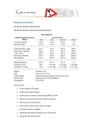
Section 6 – Specifications<br />
Weight: (1.34 kg)<br />
Size: 21 x 7 x 28 cm<br />
Acquisition Time: 0.3 sec<br />
Speed Accuracy: ±1 mph<br />
Minimum Range:<br />
• Speed Mode: 20 m<br />
• w/ Weather Filter Active: 61 m<br />
Maximum Range: <strong>1000</strong> m<br />
Speed Range: ±200 mph<br />
Range Accuracy: ±15 cm<br />
Beam Divergence: 3 milliradians nominal<br />
Laser Wavelenght: 904 nanometers nominal<br />
o<br />
o<br />
Temperature Range: -30 C to +60 C<br />
Power: Two alkaline or NiCad rechargeable C batteries providing up to 25 hours of<br />
cordless operation.<br />
Eye Safety: IEC EM60825-1 standard (FDA Class 1 CFR 21)<br />
Environment: Waterproof to IP 67 and NEMA 6<br />
Construction: All aluminium, extruded housing<br />
24<br />
© <strong>Tele</strong>-<strong>Traffic</strong> UK Ltd 2006
Section 7 – Troubleshooting Tips<br />
Unit powers OFF by itself.<br />
-or-<br />
No power at all.<br />
The in-scope red aiming dot is not visible.<br />
E01 error code. No range or speed readings.<br />
Erroneous readings/not repeatable.<br />
No serial communication.<br />
Limited Range.<br />
Contact Details<br />
What You Will See<br />
Difficult to acquire target while aiming through<br />
windshield.<br />
Difficult to acquire target while aiming through<br />
rain or snow.<br />
<strong>Tele</strong>-<strong>Traffic</strong> UK<br />
LaserTec Centre<br />
Harris Road<br />
Warwick<br />
CV34 5JU<br />
T: +44 (0) 1926 407 272<br />
F: +44 (0) 1926 407 977<br />
email: tt@teletraffic.co.uk<br />
Web: www.teletrafficuk.com<br />
• Verify that the batteries are installed correctly.<br />
• Replace the batteries.<br />
Keep in mind that the instrument automatically powers OFF if<br />
there is no instrument activity for a period of 15 minutes.<br />
• Press the TRIGGER to activate the red dot.<br />
• Press the SCOPE BRIGHTNESS button to increase the intensity<br />
of the red dot.<br />
• Adjust the polarizing filter.<br />
• Can you measure to a wall that is about 20 meters away?<br />
• Check the scope alignment.<br />
• Restore the factory defaults.<br />
• When measuring a short range to a small target, aim slightly<br />
above the target.<br />
• Do you have a clear line of sight?<br />
• Check the scope alignment.<br />
• Is it raining or foggy. If yes, is it weather filter active? If not, turn it<br />
ON. Keep in mind that the minimum range will be 61 meters.<br />
• When measuring a short range to a small target, aim slightly<br />
above the target.<br />
• Verify the cable connection.<br />
Required Action<br />
• Do you have a clear line of sight?<br />
• Rain or fog will reduce the unit’s maximum range.<br />
• Is the Weather Filter active? If not, turn it ON. Keep in mind that<br />
the minimum range will be 61 meters.<br />
• Keep in mind that acquiring a target through glass will reduce the<br />
unit’s maximum range.<br />
• Make sure the lens is clean.<br />
• Check the lens for scratches.<br />
• Is the Weather Filter active?<br />
If not, turn it ON. Keep in mind that the minimum range will be 61<br />
meters.<br />
• If the windshield is bubble-shaped, shoot through the center of<br />
the windshield.<br />
• Is the Weather Filter active?<br />
If not, turn it ON. Keep in mind that the minimum range will be 61<br />
meters.<br />
25<br />
© <strong>Tele</strong>-<strong>Traffic</strong> UK Ltd 2006