LTI 20.20 Laser Speed Measurement Devices and ... - Tele-Traffic UK
LTI 20.20 Laser Speed Measurement Devices and ... - Tele-Traffic UK
LTI 20.20 Laser Speed Measurement Devices and ... - Tele-Traffic UK

Create successful ePaper yourself
Turn your PDF publications into a flip-book with our unique Google optimized e-Paper software.
<strong>LTI</strong> <strong>20.20</strong> <strong>Laser</strong> <strong>Speed</strong> <strong>Measurement</strong> <strong>Devices</strong><br />
<strong>and</strong> LASTEC Concept DVD System<br />
Operations Manual 2008<br />
© <strong>Tele</strong>-<strong>Traffic</strong> <strong>UK</strong> Ltd 2008
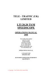
TELE-TRAFFIC (<strong>UK</strong>) LIMITED<br />
<strong>LTI</strong> <strong>20.20</strong> LASER SPEED MEASUREMENT DEVICES<br />
AND<br />
LASTEC DVD RECORDING SYSTEMS<br />
LASTEC Concept is a customer configured speed detection<br />
<strong>and</strong> enforcement system for use in the tripod mounted<br />
mobile attended mode. For the core of the system it utilises<br />
a Type Approved <strong>LTI</strong> <strong>20.20</strong> laser speed detection device<br />
<strong>and</strong> a Type Approved <strong>Tele</strong>-<strong>Traffic</strong> Display Control Unit. The<br />
remainder is tailored to the user's requirements.<br />
The system retains all the flexibility <strong>and</strong> benefits of the<br />
narrow beam laser detection approach, whilst providing<br />
instant pictures at the scene if required <strong>and</strong> data capture<br />
capable of being processed historically. The medium used is<br />
DVD -R technology which offers greater flexibility for<br />
evidence gathering in speed enforcement.<br />
The system continues to be uncomplicated in operation but<br />
does require some operator skill. Once mastered it will<br />
provide pictorial evidence of speeding offences at ranges<br />
between 20 & 550m dependent upon the lens configuration.<br />
TELE-TRAFFIC (<strong>UK</strong>) Ltd provides support in both training<br />
<strong>and</strong> technical matters. If you require any assistance please<br />
do not hesitate to contact us at:-<br />
<strong>Laser</strong>Tec Centre,<br />
C2 Harris Road,<br />
Warwick CV34 5JU<br />
Tel. No. 01926 407272<br />
Fax No. 01926 407977<br />
Email:tt@teletraffic.co.uk<br />
www.teletrafficuk.com
© Copyright – <strong>Tele</strong>-<strong>Traffic</strong> (<strong>UK</strong>) Limited 2007<br />
IMPORTANT!<br />
THESE INSTRUCTIONS SHOULD BE READ IN CONJUNCTION<br />
WITH THE OPERATORS MANUAL FOR THE APPROPRIATE <strong>LTI</strong><br />
<strong>20.20</strong> LASER SPEED MEASURING UNIT.<br />
NOTHING IN THESE INSTRUCTIONS SHOULD BE SEEN AS<br />
CONFLICTING WITH THAT MANUAL.<br />
The contents of this manual including the<br />
DVD disc remain the property of <strong>Tele</strong>-<br />
<strong>Traffic</strong> <strong>UK</strong> Ltd <strong>and</strong> are subject to<br />
Copyright.<br />
2
© Copyright – <strong>Tele</strong>-<strong>Traffic</strong> (<strong>UK</strong>) Limited 2007<br />
SECTION 1<br />
SYSTEM DESCRIPTION<br />
CONTENTS:<br />
Component Parts<br />
3
© Copyright – <strong>Tele</strong>-<strong>Traffic</strong> (<strong>UK</strong>) Limited 2007<br />
Lastec Concept Component Parts.<br />
The <strong>LTI</strong> <strong>20.20</strong> <strong>Laser</strong> is the approved measuring device that the new Lastec<br />
Concept DVD speed detection system is built around. There are however a number<br />
of new pieces of equipment <strong>and</strong> procedures within the system with which you must<br />
now become acquainted with.<br />
What follows is a brief description of the function of each piece of equipment in your<br />
particular configuration <strong>and</strong> these will vary dependent upon customer requirements.<br />
1. THE LASER.<br />
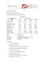
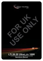
<strong>LTI</strong> <strong>20.20</strong> Ultralyte 1000 <strong>Speed</strong> <strong>Measurement</strong> <strong>Devices</strong><br />
This is a recent Type approved laser which we intend to introduction to the<br />
Lastec unit. Existing Operators may require additional training to use this<br />
type of device.<br />
Alternatively<br />
<strong>LTI</strong> <strong>20.20</strong> UltraLyte 100 <strong>Speed</strong> <strong>Measurement</strong> <strong>Devices</strong><br />
This is a Type approved <strong>Laser</strong> for use within the Lastec Concept unit.<br />
Existing Operators may require additional training to use this type of device.<br />
Alternatively<br />
<strong>LTI</strong> <strong>20.20</strong> <strong>Speed</strong>Scope <strong>Speed</strong> <strong>Measurement</strong> <strong>Devices</strong><br />
This is a Type approved <strong>Laser</strong> for use within the Lastec Concept unit.<br />
Existing Operators may require additional training to use this type of device.<br />
2. DISPLAY CONTROL UNIT (DCU)<br />
The Display Control Unit (or DCU) is the vital piece of equipment that links<br />
the live pictures obtained by the Camera to the data provided by the <strong>LTI</strong><br />
<strong>20.20</strong>. <strong>Laser</strong> Additionally it generates the data <strong>and</strong> cross hairs that appear<br />
on the video picture.<br />
It allows the Operator to set a threshold speed limit below which speed<br />
enforcement is not required.<br />
Having captured the data it will mark the DVD recorded images both visibly<br />
<strong>and</strong> invisibly in a format that is recoverable <strong>and</strong> can if required trigger a<br />
separate Video Printer.<br />
The Operator has the ability to locate the displayed data anywhere on the<br />
screen <strong>and</strong> to move <strong>and</strong> adjust the cross hairs for size <strong>and</strong> shape.<br />
For each transaction the DCU conducts a sixteen bit check sum with the <strong>LTI</strong><br />
<strong>20.20</strong> to verify the data before it is displayed <strong>and</strong> should verification not take<br />
place for any reason the unit will display an appropriate error message.<br />
4
3. VIDEO CAMERA<br />
The choice of Video Camera depends largely on the requirement for the<br />
particular application. A high resolution three chip CCD Colour Camera for<br />
high definition <strong>and</strong> picture quality has been integrated into the system.<br />
4. LENS<br />
Once again the choice of Lens is a matter for customer requirements <strong>and</strong><br />
the operational environment in which it is intended to be used. The<br />
equipment is capable of being used with a variety of Lenses <strong>and</strong> there is no<br />
reason why Operators cannot have a range of Lenses available for different<br />
scenarios.<br />
5. DVD RECORDER/MONITOR<br />
The system uses a Panasonic LQ-MD800 medical grade DVD –R recorder is<br />
configured to PAL/VHS for optimum performance.<br />
6. PRINTER<br />
The st<strong>and</strong>ard configuration has the flexibility to connect a st<strong>and</strong> alone mono<br />
thermal printer if required. Although the camera <strong>and</strong> DVD are in the colour<br />
format there are distinct advantages to using Mono prints. Most important is<br />
the element of speed. This unit will produce a Print of the offender within<br />
seven seconds. The print is then available for viewing on site if required.<br />
Colour Printers are much slower (typically 45 seconds for each Print).<br />
7. POWER INVERTER<br />
Video Printers generally require 220v Ac power supplies <strong>and</strong> it is therefore<br />
necessary to invert the 12v DC power supply to that rating. You will later<br />
note that the 12v DC supply is independent of that for the remainder of the<br />
equipment.<br />
8. POWER PACKS<br />
The equipment is supplied complete with a self contained 12 v DC TELE-<br />
TRAFFIC POWERSTATION four outlet rechargeable capacity.<br />
9. EQUIPMENT CARRYING CASES<br />
The st<strong>and</strong>ard configuration includes two Carrying Cases one of which for the<br />
DVD Recorder <strong>and</strong> the other is a storage Peli-box for the Camera/<strong>Laser</strong><br />
top unit. This simplifies the task of connecting the equipment for the<br />
Operator.<br />
10. CABLES<br />
Each configuration is provided with the necessary cables to connect the<br />
equipment. Whilst care should always be taken by Operators in making the<br />
connections you will find that they will only fit one way. All are of the latched<br />
type or military specification to prevent accidental disconnection.<br />
11. TRIPOD<br />
The equipment is operated from a LIBEC FT 20-J Heavy Tripod fitted with a<br />
LIBEC H37 or H38 Fluid Video Head <strong>and</strong> LIBEC 2273 Carry Bag.<br />
© Copyright – <strong>Tele</strong>-<strong>Traffic</strong> (<strong>UK</strong>) Limited 2007<br />
5
12. TAPELOGGER<br />
Here there is a change to the previous Lastec, the tape logger works<br />
automatically within this system for fast data transfer to the Event Reader in<br />
the back office procedures.<br />
13. TELE-TRAFFIC EVENT READER (Back Office Data Download)<br />
Some forces prefer to take prints only at the scene, others may wish to<br />
capture offences only onto DVD Disc for later processing.<br />
The Event Reader will take a signal from a disk <strong>and</strong> identify each offence<br />
contained upon it. It will then automatically initiate a print of the picture on a<br />
thermal printer (Mono or Colour). It is capable of automatically downloading<br />
that data into all recognised computer generated ticketing systems.<br />
© Copyright – <strong>Tele</strong>-<strong>Traffic</strong> (<strong>UK</strong>) Limited 2007<br />
6
© Copyright – <strong>Tele</strong>-<strong>Traffic</strong> (<strong>UK</strong>) Limited 2007<br />
SECTION 2<br />
SYSTEM APPLICATION<br />
7
© Copyright – <strong>Tele</strong>-<strong>Traffic</strong> (<strong>UK</strong>) Limited 2007<br />
LASTEC CONCEPT<br />
SYSTEM APPLICATION<br />
Having identified each individual module of the Lastec Concept DVD configuration it<br />
will now be helpful to have a general underst<strong>and</strong>ing of how it integrates together.<br />
Whatever the <strong>LTI</strong> <strong>20.20</strong> <strong>Laser</strong> fitted the system the Operator needs to be familiar<br />
with <strong>and</strong> aware of all of its functions. Nothing has changed in that respect <strong>and</strong><br />
additionally the skills acquired in operational practise remain the same.<br />
The Red Dot within the sighting scope should be the operator’s only targeting<br />
method <strong>and</strong> the checks <strong>and</strong> evidential requirements of this function are identical<br />
when used with DVD recording equipment. Beware that the Ultralyte lasers have a<br />
power saving feature that turns off the red dot after 20 seconds. To reinstate the<br />
laser should this happen press the trigger <strong>and</strong> release. The red dot will reappear<br />
<strong>and</strong> the laser is ready for the next measurement cycle.<br />
The data that it provides is also the same <strong>and</strong> will still appear on the display on the<br />
<strong>LTI</strong> <strong>20.20</strong> <strong>Laser</strong> whatever is connected through the serial port.<br />
The Camera will give a picture by means of a st<strong>and</strong>ard video signal to whatever<br />
equipment it is connected. (The technical term is 1 volt peak to peak).<br />
When working together the <strong>LTI</strong> <strong>20.20</strong> <strong>Laser</strong> <strong>and</strong> the Camera will provide data <strong>and</strong><br />
signals to the Display Control Unit (DCU) <strong>and</strong> the Tape logger.<br />
The DCU will firstly perform a 16 bit check sum between itself <strong>and</strong> the <strong>LTI</strong> <strong>20.20</strong><br />
<strong>Laser</strong> to ensure that the data that it is receiving has not been corrupted in<br />
transmission by any external source. Should this check not be satisfactory then an<br />
error message (BAD CRC or RS232) will be generated.<br />
If this check is satisfactory then the data from the <strong>LTI</strong> <strong>20.20</strong> <strong>Laser</strong> is inserted by the<br />
Display Control Unit onto the video signal both visibly <strong>and</strong> also invisibly in the form<br />
of data marks which are buried in the D.V.D disc.<br />
The Display Control Unit will also examine the speed data provided from the <strong>LTI</strong><br />
<strong>20.20</strong> <strong>and</strong> check it against the threshold speed set by the Operator. If the checked<br />
speed is in excess of the set threshold speed a further data mark is inserted both<br />
visibly <strong>and</strong> invisibly <strong>and</strong> a "print picture" comm<strong>and</strong> is sent to the Printer. (This is if<br />
Prints are required at the speed check site.)<br />
Having merged all this information the Display Control Unit provides a composite<br />
video signal on a loop both to the DVD Recorder/Monitor <strong>and</strong> to the Printer.<br />
N.B. This last fact is important because it means that any Prints made at the<br />
speed check site at the time that the signal is provided to the Printer is "best<br />
evidence". In that event it may be deemed to be unnecessary to retain the DVD<br />
Disc as evidence.<br />
8
Alternatively if Prints are not taken as above <strong>and</strong> the disk is later analysed at an<br />
administrative unit then the DVD Disk becomes "best evidence" <strong>and</strong> must be<br />
retained. Any Prints taken in any such analysis are likely to be deemed “secondary<br />
evidence”.<br />
The Memory Buffer in the Printer, (if fitted) allows an Operator to target vehicles at<br />
very short intervals typically under one second <strong>and</strong> thus the equipment in this<br />
configuration remains as fast as the <strong>LTI</strong> <strong>20.20</strong> <strong>Laser</strong> in the conventional h<strong>and</strong> held<br />
mode.<br />
The video signal on the loop is simultaneously received by the DVD<br />
Recorder/Monitor <strong>and</strong> recorded on the DVD disk <strong>and</strong> in accordance with the<br />
comments above provides "best evidence". The data appears visibly in plain<br />
English <strong>and</strong> provides:<br />
© Copyright – <strong>Tele</strong>-<strong>Traffic</strong> (<strong>UK</strong>) Limited 2007<br />
TIME, DATE, SITE (or OFFICER'S REFERENCE)<br />
SPEED <strong>and</strong> RANGE TO TARGET<br />
If the target vehicle is above the set threshold speed then an asterisk will also<br />
appear.<br />
The position of the data on the Screen can be controlled by the Operator.<br />
At the same time, the data is inserted on the DVD Disk in an invisible form in a<br />
technique that resembles a bar code.<br />
This completes the sequence of events at the scene but as suggested above it is<br />
possible to analyse the DVD disk in the office situation. This process uses the<br />
Event Reader in conjunction with the Printer <strong>and</strong> means that when the video signal<br />
is played through it a search is automatically conducted for data over the threshold<br />
speed <strong>and</strong> a Video Print produced. This can be an unattended operation.<br />
Data can be downloaded simultaneously into a Computer for administrative<br />
purposes.<br />
In addition to the asterisk there is another symbol that appears only in the record<br />
mode. Situated in the bottom left corner of the screen there is a hash mark (#)<br />
feature which when pressed on screen allows the operator to mark an event.<br />
( An example of this might be if the operator has set the threshold limit to enforce for<br />
cars <strong>and</strong> sees another type of vehicle exceeding the permitted speed limit for that<br />
class of vehicle he can mark the event <strong>and</strong> still obtain a speed reading which can be<br />
downloaded <strong>and</strong> identified later. Other examples might be No seat belt or using a<br />
mobile phone whilst driving.)<br />
9
© Copyright – <strong>Tele</strong>-<strong>Traffic</strong> (<strong>UK</strong>) Limited 2007<br />
SECTION 3<br />
OPERATOR INSTRUCTIONS<br />
CONTENTS:<br />
Assembly Procedure<br />
Camera Control Unit Controls<br />
Camera Control Unit Adjustments<br />
10
© Copyright – <strong>Tele</strong>-<strong>Traffic</strong> (<strong>UK</strong>) Limited 2007<br />
LASTEC CONCEPT<br />
OPERATOR INSTRUCTIONS<br />
Your LASTEC Concept system comprises the following modules. Check that you<br />
have them available.<br />
1. The appropriate <strong>LTI</strong> <strong>20.20</strong> <strong>Laser</strong> with Colour Video Camera,<br />
adjustable camera platform, Colour Video Monitor/Viewer, Lens <strong>and</strong><br />
Mount<br />
2. A Touch Screen Comm<strong>and</strong> System<br />
3. Automatic Tape logger<br />
4. A Panasonic LQ-MD800 DVD -R Recorder<br />
5. Video Printer (Sold as a separate unit)<br />
6. Power Inverter<br />
7. Connecting cables<br />
8. PowerStation<br />
9. Tripod<br />
11
© Copyright – <strong>Tele</strong>-<strong>Traffic</strong> (<strong>UK</strong>) Limited 2007<br />
ASSEMBLY PROCEDURE<br />
1. Mount the <strong>LTI</strong> <strong>20.20</strong> <strong>Laser</strong> <strong>and</strong> camera/monitor assembly on the tripod using the mounting<br />
plate provided.<br />
2. Fit the chosen Lens to the Camera if smaller than a Sigma 135-400mm. Other lenses such<br />
as the Sigma 50-500mm remain fixed to the camera.<br />
3. Connect the power cables from the DVD equipment to the power sockets on the front of the<br />
PowerStation or vehicle 12VDC supply.<br />
4. Connect the Umbilical cable to the underside multi connector on the mounting plate <strong>and</strong><br />
then to the rear of the DVD Unit. (Note this umbilical cable only fits one way round.)<br />
5. Ensure the Video Printer is switched "on" if connected.<br />
6. Switch "on" the Lastec Concept system Recorder/Monitor/Camera by using the switch on<br />
the front of the DVD Base Unit. There is a small delay while the system checks itself <strong>and</strong><br />
then the display touch screen becomes active <strong>and</strong> two small block displays appear showing<br />
the letters ‘DVD’ & ‘DCU’<br />
7. When the unit is first powered on it will clear all previous data stored in the logger.<br />
8. A 50 second timer will be displayed on the screen <strong>and</strong> start counting down, this is to allow<br />
the DVD to go through its self check mode & become available for use. This period also<br />
allows the system to stabilize.<br />
9. After this is complete the system will check its RS232 link to the DVD & then the DVD’s<br />
ROM version. Providing both these pass the system will progress to the next step, if not a<br />
fail message will be displayed & the system will lock out.<br />
10. The system will now proceed in to its user state.<br />
12
© Copyright – <strong>Tele</strong>-<strong>Traffic</strong> (<strong>UK</strong>) Limited 2007<br />
YOU MAY NOW BEGIN YOUR OPERATIONAL CHECKS<br />
AND SET UP PROCEDURES<br />
(a) Carry out the Scope ‘red dot’ alignment checks in accordance with the appropriate <strong>LTI</strong><br />
<strong>20.20</strong> <strong>Laser</strong> manual.<br />
(b) Check that the ‘red dot’ in the Scope is approximately in the centre of the picture provided<br />
by the Camera <strong>and</strong> adjust the Camera platform if necessary by using the Knobs on the side<br />
(horizontal) <strong>and</strong> underneath (vertical).<br />
Ensure that the Camera Lens is set to give a clear picture at the required focal length<br />
before adjustment of camera position. Aim the <strong>Laser</strong> ‘red dot’ at a suitable static target.<br />
(The distance to the target should be at the end of the visible Licence Plate recognition<br />
distance.) This is Lens dependent.<br />
(c) Check that the crosshair display on the Monitor is in the favoured or centre position. If not,<br />
adjust accordingly.<br />
The Video Printer may be powered separately from a car but the DCU, Video<br />
Camera <strong>and</strong> <strong>LTI</strong> <strong>20.20</strong> <strong>Laser</strong> should not be powered from a vehicle power<br />
supply as stipulated in Section 6.2.2 of the <strong>Laser</strong> H<strong>and</strong>book (Second Edition)<br />
Publication 27/92.<br />
(d) FINALLY: Carry out any additional operational checks required by the current<br />
Association of Chief Police Officers (Code of Practice) guidelines.<br />
11. On Start-up all previous data will be cleared from the data log.<br />
Once the data log has been cleared the main screen is then displayed as shown below.<br />
The user will now be prompted with 2 options on the bottom of the screen DVD <strong>and</strong> DCU.<br />
N<br />
18:25:15 R 48 AAAAAAAAAA<br />
03-08-04<br />
DVD DCU<br />
13
© Copyright – <strong>Tele</strong>-<strong>Traffic</strong> (<strong>UK</strong>) Limited 2007<br />
ADJUSTING THE DISPLAY CONTROL UNIT<br />
The LASTEC Concept is a DVD recoding system which captures text overlaid live video (via a 3<br />
chip CCD camera), the system is controlled from a touch panel located over the viewing monitor at<br />
the control end of the system.<br />
The system is designed when powered up to run through a series of internal self checks which are<br />
indicated on the viewing monitor should any fail.<br />
When the unit is in user mode after passing its self checks the operator will navigate via the menu<br />
system to the DCU (display control unit) <strong>and</strong> set required parameters e.g. date, time, user number,<br />
site number <strong>and</strong> speed thresholds.<br />
By pressing the DCU Option the user will gain access to the DCU setup controls, press ENTER<br />
<strong>and</strong> this will give the user access to the DCU setup menu.<br />
This menu is navigated by using the UP, DOWN, LEFT, RIGHT & ENTER on screen buttons.<br />
Finally to exit this menu press the EXIT button to return to the DVD & DCU menu options.<br />
This is a major change from the previous unit ALL controls are now accessed through an<br />
on screen touch menu.<br />
14
Entering <strong>and</strong> navigating the DCU menu<br />
Press the DCU Option.<br />
The DCU menu allows complete access to all the system control functions.<br />
On entering the main menu, the following menu will be displayed.<br />
© Copyright – <strong>Tele</strong>-<strong>Traffic</strong> (<strong>UK</strong>) Limited 2007<br />
SET LIMIT OPTIONS<br />
SET USER NUMBER<br />
SET TIME/DATE<br />
SET CROSS-HAIR<br />
SET DISPLAY OPTIONS<br />
DATA LOG OPTIONS<br />
SYSTEM OPTIONS<br />
� EXIT<br />
Use the ‘Up ’ <strong>and</strong> ‘Down Options’ to change the highlighted selection within a menu. Use the ‘Enter<br />
Option’ to enter a highlighted sub-menu or control function selection.<br />
Setting the <strong>Speed</strong> Enforcement Threshold<br />
To set the <strong>Speed</strong> Enforcement Threshold, follow the steps below.<br />
1. Enter the DCU menu by pressing symbol on screen.<br />
On entering the main menu, the following menu will be displayed.<br />
SET LIMIT OPTIONS<br />
SET USER NUMBER<br />
SET TIME/DATE<br />
SET CROSS-HAIR<br />
SET DISPLAY OPTIONS<br />
DATA LOG OPTIONS<br />
SYSTEM OPTIONS<br />
� EXIT<br />
EXIT<br />
UP DOWN LEFT RIGHT ENTER<br />
EXIT<br />
UP DOWN LEFT RIGHT ENTER<br />
15
2. Highlight the ‘SET LIMIT OPTIONS’ selection<br />
Use the ‘Up Option’ or ‘Down Option’ to move the selection arrow to highlight the ‘SET LIMIT<br />
OPTIONS’ selection as shown below.<br />
3. Enter the ‘SET LIMIT OPTIONS’ menu<br />
© Copyright – <strong>Tele</strong>-<strong>Traffic</strong> (<strong>UK</strong>) Limited 2007<br />
� SET LIMIT OPTIONS<br />
SET USER NUMBER<br />
SET TIME/DATE<br />
SET CROSS-HAIR<br />
SET DISPLAY OPTIONS<br />
DATA LOG OPTIONS<br />
SYSTEM OPTIONS<br />
EXIT<br />
With the ‘SET LIMIT OPTIONS’ selection highlighted, press the ‘Enter Option’ to enter the ‘SET<br />
LIMIT OPTIONS’ menu. On entering the ‘SET LIMIT OPTIONS’ menu, the following menu will be<br />
displayed.<br />
SET SPEED THRESHOLD<br />
SET SPEED TIMEOUT<br />
� EXIT<br />
EXIT<br />
UP DOWN LEFT RIGHT ENTER<br />
EXIT<br />
UP DOWN LEFT RIGHT ENTER<br />
16
4. Highlight the ‘SET SPEED THRESHOLD’ selection<br />
Use the ‘Up Option’ or ‘Down Option’ to move the selection arrow to highlight the ‘SET SPEED<br />
THRESHOLD’ selection as shown below.<br />
© Copyright – <strong>Tele</strong>-<strong>Traffic</strong> (<strong>UK</strong>) Limited 2007<br />
� SET SPEED THRESHOLD<br />
SET SPEED TIMEOUT<br />
EXIT<br />
5. Entering the ‘SET SPEED THRESHOLD’ control function<br />
With the ‘SET SPEED THRESHOLD’ selection highlighted, press the ‘Enter Option’ to enter the<br />
‘SET SPEED THRESHOLD’ control function. On entering the ‘SET SPEED THRESHOLD’ control<br />
function, the following screen will be displayed. The adjustable speed limit will be flashing.<br />
SPEED THRESHOLD<br />
070 JGJ<br />
EXIT<br />
UP DOWN LEFT RIGHT ENTER<br />
EXIT<br />
UP DOWN LEFT RIGHT ENTER<br />
17
6. Adjusting the speed limit in the ‘SET SPEED THRESHOLD’ control function<br />
Use the ‘Up Option’ to increment the speed limit or use the ‘Down Option’ decrement the speed<br />
limit. The speed enforcement threshold can be set at any whole number between 000 <strong>and</strong> 255.<br />
The alpha code to the right of the speed limit will change in accordance to changes made to the<br />
speed limit. When the desired speed limit has been chosen <strong>and</strong> is showing, press the ‘Enter<br />
Option’ to save the change <strong>and</strong> return to the ‘SET LIMIT OPTIONS’ menu.<br />
Note: The Operator should set this value to one lower than the speed he or she intends to enforce<br />
at!<br />
Setting the speed timeout<br />
To set the speed timeout, follow the steps below.<br />
1. Enter the DCU menu by pressing symbol on screen<br />
On entering the main menu, the following menu will be displayed.<br />
© Copyright – <strong>Tele</strong>-<strong>Traffic</strong> (<strong>UK</strong>) Limited 2007<br />
SET LIMIT OPTIONS<br />
SET USER NUMBER<br />
SET TIME/DATE<br />
SET CROSS-HAIR<br />
SET DISPLAY OPTIONS<br />
DATA LOG OPTIONS<br />
SYSTEM OPTIONS<br />
� EXIT<br />
EXIT<br />
UP DOWN LEFT RIGHT ENTER<br />
18
2. Highlight the ‘SET LIMIT OPTIONS’ selection<br />
Use the ‘Up Option’ or ‘Down Option’ to move the selection arrow to highlight the ‘SET LIMIT<br />
OPTIONS’ selection as shown below.<br />
3. Enter the ‘SET LIMIT OPTIONS’ menu<br />
© Copyright – <strong>Tele</strong>-<strong>Traffic</strong> (<strong>UK</strong>) Limited 2007<br />
� SET LIMIT OPTIONS<br />
SET USER NUMBER<br />
SET TIME/DATE<br />
SET CROSS-HAIR<br />
SET DISPLAY OPTIONS<br />
DATA LOG OPTIONS<br />
SYSTEM OPTIONS<br />
EXIT<br />
UP DOWN LEFT RIGHT ENTER<br />
With the ‘SET LIMIT OPTIONS’ selection highlighted, press the ‘Enter Option’ to enter the ‘SET<br />
LIMIT OPTIONS’ menu. On entering the ‘SET LIMIT OPTIONS’ menu, the following menu will be<br />
displayed.<br />
SET SPEED LIMIT<br />
SET SPEED TIMEOUT<br />
� EXIT<br />
EXIT<br />
EXIT<br />
UP DOWN LEFT RIGHT ENTER<br />
19
4. Highlight the ‘SET SPEED TIMEOUT’ selection<br />
Use the ‘Up Option’ or ‘Down Option’ to move the selection arrow to highlight the ‘SET SPEED<br />
TIMEOUT’ selection as shown below<br />
© Copyright – <strong>Tele</strong>-<strong>Traffic</strong> (<strong>UK</strong>) Limited 2007<br />
SET SPEED LIMIT<br />
� SET SPEED TIMEOUT<br />
EXIT<br />
5. Entering the ‘SET SPEED TIMEOUT’ control function<br />
With the ‘SET SPEED TIMEOUT’ selection highlighted, press the ‘Enter Option’ to enter the ‘SET<br />
SPEED TIMEOUT’ control function. On entering the ‘SET SPEED TIMEOUT’ control function, the<br />
following screen will be displayed. The adjustable speed timeout will be flashing.<br />
SPEED TIMEOUT<br />
060<br />
EXIT<br />
UP DOWN LEFT RIGHT ENTER<br />
EXIT<br />
UP DOWN LEFT RIGHT ENTER<br />
20
6. Adjusting the speed limit in the ‘SET SPEED TIMEOUT’ control function<br />
Use the ‘Up Option’ to increment the speed limit or use the ‘Down Option’ decrement the speed<br />
timeout. The speed timeout can be set at any whole number between 001 <strong>and</strong> 250. When the<br />
desired speed timeout has been chosen <strong>and</strong> is showing, press the ‘Enter Option’ to save the<br />
change <strong>and</strong> return to the ‘SET LIMIT OPTIONS’ menu.<br />
Note: The Manufacturers Recommended setting for this value is 060<br />
Whilst in operational use, improvements to the system have been made so that the<br />
message TIME OUT has now been removed. However the information messages such as<br />
E01,E02 <strong>and</strong> E03 will still appear on the screen for a set period <strong>and</strong> this setting adjust that<br />
time period.<br />
Setting the user number<br />
To set the user number, follow the steps below.<br />
1. Enter the DCU menu by pressing the symbol on screen.<br />
On entering the main menu, the following menu will be displayed.<br />
© Copyright – <strong>Tele</strong>-<strong>Traffic</strong> (<strong>UK</strong>) Limited 2007<br />
SET LIMIT OPTIONS<br />
SET USER NUMBER<br />
SET TIME/DATE<br />
SET CROSS-HAIR<br />
SET DISPLAY OPTIONS<br />
DATA LOG OPTIONS<br />
SYSTEM OPTIONS<br />
� EXIT<br />
EXIT<br />
UP DOWN LEFT RIGHT ENTER<br />
21
2. Highlight the ‘SET USER NUMBER’ selection<br />
Use the ‘Up Option’ or ‘Down Option’ to move the selection arrow to highlight the ‘SET USER<br />
NUMBER’ selection as shown below.<br />
© Copyright – <strong>Tele</strong>-<strong>Traffic</strong> (<strong>UK</strong>) Limited 2007<br />
SET LIMIT OPTIONS<br />
� SET USER NUMBER<br />
SET TIME/DATE<br />
SET CROSS-HAIR<br />
SET DISPLAY OPTIONS<br />
DATA LOG OPTIONS<br />
SYSTEM OPTIONS<br />
EXIT<br />
3. Entering the ‘SET USER NUMBER’ control function<br />
With the ‘SET USER NUMBER’ selection highlighted, press the ‘Enter Option’ to enter the ‘SET<br />
USER NUMBER’ control function.<br />
On entering the ‘SET USER NUMBER’ control function, the following screen will be displayed. The<br />
left-most character of the adjustable 10-character user number will be flashing.<br />
USER NUMBER<br />
AAAAAAAAAA<br />
EXIT<br />
UP DOWN LEFT RIGHT ENTER<br />
EXIT<br />
UP DOWN LEFT RIGHT ENTER<br />
22
4. Adjusting the user number in the ‘SET USER NUMBER’ control function<br />
Use the ‘Up Option’ to increment the flashing user number character or use the ‘Down Option’<br />
decrement the flashing user number character. The user number characters can be set at any<br />
whole number between 0 <strong>and</strong> 9, any upper case letter between A <strong>and</strong> Z, or a space.<br />
Use the ‘Left Option’ <strong>and</strong> ‘Right Option’ to select a different character of the user number to be<br />
changed. When the desired user number has been chosen <strong>and</strong> is showing, press the ‘Enter<br />
Option’ to save the changes <strong>and</strong> return to the main menu.<br />
Setting the time <strong>and</strong> date<br />
To set the time <strong>and</strong> date, follow the steps below.<br />
1. Enter the DCU menu by pressing the symbol on screen.<br />
On entering the main menu, the following menu will be displayed.<br />
© Copyright – <strong>Tele</strong>-<strong>Traffic</strong> (<strong>UK</strong>) Limited 2007<br />
SET LIMIT OPTIONS<br />
SET USER NUMBER<br />
SET TIME/DATE<br />
SET CROSS-HAIR<br />
SET DISPLAY OPTIONS<br />
DATA LOG OPTIONS<br />
SYSTEM OPTIONS<br />
� EXIT<br />
EXIT<br />
UP DOWN LEFT RIGHT ENTER<br />
23
2. Highlight the ‘SET TIME/DATE’ selection<br />
Use the ‘Up Option’ or ‘Down Option’ to move the selection arrow to highlight the ‘SET<br />
TIME/DATE’ selection as shown below.<br />
© Copyright – <strong>Tele</strong>-<strong>Traffic</strong> (<strong>UK</strong>) Limited 2007<br />
SET LIMIT OPTIONS<br />
SET USER NUMBER<br />
� SET TIME/DATE<br />
SET CROSS-HAIR<br />
SET DISPLAY OPTIONS<br />
DATA LOG OPTIONS<br />
SYSTEM OPTIONS<br />
EXIT<br />
3. Entering the ‘SET TIME/DATE’ control function<br />
With the ‘SET TIME/DATE’ selection highlighted, press the ‘Enter Option’ to enter the ‘SET<br />
TIME/DATE’ control function. On entering the ‘SET TIME/DATE’ control function, the following<br />
screen will be displayed. The hours of the adjustable time <strong>and</strong> date settings will be flashing.<br />
TIME DATE<br />
19:38:44 02-08-04<br />
EXIT<br />
UP DOWN LEFT RIGHT ENTER<br />
EXIT<br />
UP DOWN LEFT RIGHT ENTER<br />
24
4. Adjusting the time/date in the ‘SET TIME/DATE’ control function<br />
Use the ‘Up Option’ to increment the flashing time/date component or use the ‘Down Option’<br />
decrement the flashing time/date component. Use the ‘Left Option’ <strong>and</strong> ‘Right Option’ to select a<br />
time/date component to be changed.<br />
When the desired time/date has been chosen <strong>and</strong> is showing, press the ‘Enter Option’ to save the<br />
changes <strong>and</strong> return to the main menu.<br />
Setting the cross-hair position<br />
To set the cross-hair position, follow the steps below.<br />
1. Enter the DCU menu by pressing the symbol on screen.<br />
On entering the main menu, the following menu will be displayed.<br />
© Copyright – <strong>Tele</strong>-<strong>Traffic</strong> (<strong>UK</strong>) Limited 2007<br />
SET LIMIT OPTIONS<br />
SET USER NUMBER<br />
SET TIME/DATE<br />
SET CROSS-HAIR<br />
SET DISPLAY OPTIONS<br />
DATA LOG OPTIONS<br />
SYSTEM OPTIONS<br />
� EXIT<br />
EXIT<br />
UP DOWN LEFT RIGHT ENTER<br />
25
2. Highlight the ‘SET CROSS-HAIR’ selection<br />
Use the ‘Up Option’ or ‘Down Option’ to move the selection arrow to highlight the ‘SET CROSS-<br />
HAIR’ selection as shown below.<br />
3. Enter the ‘SET CROSS-HAIR’ menu<br />
© Copyright – <strong>Tele</strong>-<strong>Traffic</strong> (<strong>UK</strong>) Limited 2007<br />
SET LIMIT OPTIONS<br />
SET USER NUMBER<br />
SET TIME/DATE<br />
� SET CROSS-HAIR<br />
SET DISPLAY OPTIONS<br />
DATA LOG OPTIONS<br />
SYSTEM OPTIONS<br />
EXIT<br />
With the ‘SET CROSS-HAIR’ selection highlighted, press the ‘Enter Option’ to enter the ‘SET<br />
CROSS-HAIR’ menu. On entering the ‘SET CROSS-HAIR’ menu, the following menu will be<br />
displayed.<br />
SET POSITION<br />
SET TYPE<br />
SET SIZE<br />
SET GAP<br />
� EXIT<br />
EXIT<br />
UP DOWN LEFT RIGHT ENTER<br />
EXIT<br />
UP DOWN LEFT RIGHT ENTER<br />
26
4. Highlight the ‘SET POSITION’ selection<br />
Use the ‘Up Option’ or ‘Down Option’ to move the selection arrow to highlight the ‘SET POSITION’<br />
selection as shown below<br />
© Copyright – <strong>Tele</strong>-<strong>Traffic</strong> (<strong>UK</strong>) Limited 2007<br />
� SET POSITION<br />
SET TYPE<br />
SET SIZE<br />
SET GAP<br />
EXIT<br />
5. Entering the ‘SET POSITION’ control function<br />
With the ‘SET POSITION’ selection highlighted, press the ‘Enter Option’ to enter the ‘SET<br />
POSITION’ control function. On entering the ‘SET POSITION’ control function, the following screen<br />
will be displayed.<br />
POSITION: HORIZ= 130 VERTIC= 120<br />
EXIT<br />
UP DOWN LEFT RIGHT ENTER<br />
EXIT<br />
UP DOWN LEFT RIGHT ENTER<br />
27
6. Adjusting the cross-hair position in the ‘SET POSITION’ control function<br />
Use the ‘Up Option’ to move the cross-hair up, use the ‘Down Option’ to move the cross-hair down,<br />
use the ‘Left Option’ to move the cross-hair left <strong>and</strong> use the ‘Right Option’ to move the cross-hair<br />
right. The horizontal <strong>and</strong> vertical co-ordinates are shown as values at the top of the screen.<br />
The horizontal co-ordinate can be any whole number between 000 <strong>and</strong> 255, <strong>and</strong> the vertical coordinate<br />
can be any whole number between 000 <strong>and</strong> 233.<br />
When the desired cross-hair position has been chosen <strong>and</strong> is showing, press the ‘Enter Option’ to<br />
save the changes <strong>and</strong> return to the ‘SET CROSS-HAIR’ menu.<br />
Setting the cross-hair type<br />
To set the cross-hair type, follow the steps below.<br />
1. Enter the DCU menu by pressing the symbol on screen.<br />
On entering the main menu, the following menu will be displayed.<br />
© Copyright – <strong>Tele</strong>-<strong>Traffic</strong> (<strong>UK</strong>) Limited 2007<br />
SET LIMIT OPTIONS<br />
SET USER NUMBER<br />
SET TIME/DATE<br />
SET CROSS-HAIR<br />
SET DISPLAY OPTIONS<br />
DATA LOG OPTIONS<br />
SYSTEM OPTIONS<br />
� EXIT<br />
EXIT<br />
UP DOWN LEFT RIGHT ENTER<br />
28
2. Highlight the ‘SET CROSS-HAIR’ selection<br />
Use the ‘Up Option’ or ‘Down Option’ to move the selection arrow to highlight the ‘SET CROSS-<br />
HAIR’ selection as shown below.<br />
3. Enter the ‘SET CROSS-HAIR’ menu<br />
© Copyright – <strong>Tele</strong>-<strong>Traffic</strong> (<strong>UK</strong>) Limited 2007<br />
SET LIMIT OPTIONS<br />
SET USER NUMBER<br />
SET TIME/DATE<br />
� SET CROSS-HAIR<br />
SET DISPLAY OPTIONS<br />
DATA LOG OPTIONS<br />
SYSTEM OPTIONS<br />
EXIT<br />
With the ‘SET CROSS-HAIR’ selection highlighted, press the ‘Enter Option’ to enter the ‘SET<br />
CROSS-HAIR’ menu. On entering the ‘SET CROSS-HAIR’ menu, the following menu will be<br />
displayed.<br />
SET POSITION<br />
SET TYPE<br />
SET SIZE<br />
SET GAP<br />
� EXIT<br />
EXIT<br />
UP DOWN LEFT RIGHT ENTER<br />
EXIT<br />
UP DOWN LEFT RIGHT ENTER<br />
29
4. Highlight the ‘SET TYPE’ selection<br />
Use the ‘Up Option’ or ‘Down Option’ to move the selection arrow to highlight the ‘SET TYPE’<br />
selection as shown below<br />
© Copyright – <strong>Tele</strong>-<strong>Traffic</strong> (<strong>UK</strong>) Limited 2007<br />
SET POSITION<br />
� SET TYPE<br />
SET SIZE<br />
SET GAP<br />
EXIT<br />
5. Entering the ‘SET TYPE’ control function<br />
With the ‘SET TYPE’ selection highlighted, press the ‘Enter Option’ to enter the ‘SET TYPE’ control<br />
function. On entering the ‘SET TYPE’ control function, the following screen will be displayed.<br />
TYPE: OPEN WHITE CROSS-HAIR<br />
EXIT<br />
UP DOWN LEFT RIGHT ENTER<br />
EXIT<br />
UP DOWN LEFT RIGHT ENTER<br />
30
6. Adjusting the cross-hair type in the ‘SET TYPE’ control function<br />
Use the ‘Up Option’ or use the ‘Down Option’ to change the cross-hair type. The cross-hair type<br />
name is shown at the top of the screen. When the desired cross-hair type has been chosen <strong>and</strong> is<br />
showing, press the ‘Enter Option’ to save the change <strong>and</strong> return to the ‘SET CROSS-HAIR’ menu.<br />
The available cross-hair types are shown below:-<br />
© Copyright – <strong>Tele</strong>-<strong>Traffic</strong> (<strong>UK</strong>) Limited 2007<br />
TYPE: OPEN WHITE CROSS-HAIR<br />
TYPE: OPEN BLACK CROSS-HAIR<br />
EXIT<br />
UP DOWN LEFT RIGHT ENTER<br />
EXIT<br />
UP DOWN LEFT RIGHT ENTER<br />
31
© Copyright – <strong>Tele</strong>-<strong>Traffic</strong> (<strong>UK</strong>) Limited 2007<br />
TYPE: CLOSED WHITE CROSS-HAIR<br />
TYPE: CLOSED BLACK CROSS-HAIR<br />
TYPE: WHITE BOX<br />
EXIT<br />
UP DOWN LEFT RIGHT ENTER<br />
UP DOWN LEFT RIGHT ENTER<br />
EXIT<br />
UP DOWN LEFT RIGHT ENTER<br />
EXIT<br />
32
© Copyright – <strong>Tele</strong>-<strong>Traffic</strong> (<strong>UK</strong>) Limited 2007<br />
TYPE: BLACK BOX<br />
TYPE: OFF<br />
Setting the cross-hair size<br />
To set the cross-hair size, follow the steps below.<br />
1. Enter the DCU menu by pressing the symbol on screen.<br />
On entering the main menu, the following menu will be displayed.<br />
SET LIMIT OPTIONS<br />
SET USER NUMBER<br />
SET TIME/DATE<br />
SET CROSS-HAIR<br />
SET DISPLAY OPTIONS<br />
DATA LOG OPTIONS<br />
SYSTEM OPTIONS<br />
� EXIT<br />
EXIT<br />
UP DOWN LEFT RIGHT ENTER<br />
EXIT<br />
UP DOWN LEFT RIGHT ENTER<br />
EXIT<br />
UP DOWN LEFT RIGHT ENTER<br />
33
2. Highlight the ‘SET CROSS-HAIR’ selection<br />
Use the ‘Up Option’ or ‘Down Option’ to move the selection arrow to highlight the ‘SET CROSS-<br />
HAIR’ selection as shown below.<br />
3. Enter the ‘SET CROSS-HAIR’ menu<br />
© Copyright – <strong>Tele</strong>-<strong>Traffic</strong> (<strong>UK</strong>) Limited 2007<br />
SET LIMIT OPTIONS<br />
SET USER NUMBER<br />
SET TIME/DATE<br />
� SET CROSS-HAIR<br />
SET DISPLAY OPTIONS<br />
DATA LOG OPTIONS<br />
SYSTEM OPTIONS<br />
EXIT<br />
With the ‘SET CROSS-HAIR’ selection highlighted, press the ‘Enter Option’ to enter the ‘SET<br />
CROSS-HAIR’ menu. On entering the ‘SET CROSS-HAIR’ menu, the following menu will be<br />
displayed.<br />
SET POSITION<br />
SET TYPE<br />
SET SIZE<br />
SET GAP<br />
� EXIT<br />
EXIT<br />
UP DOWN LEFT RIGHT ENTER<br />
EXIT<br />
UP DOWN LEFT RIGHT ENTER<br />
34
4. Highlight the ‘SET SIZE’ selection<br />
Use the ‘Up Option’ or ‘Down Option’ to move the selection arrow to highlight the ‘SET SIZE’<br />
selection as shown below<br />
© Copyright – <strong>Tele</strong>-<strong>Traffic</strong> (<strong>UK</strong>) Limited 2007<br />
SET POSITION<br />
SET TYPE<br />
� SET SIZE<br />
SET GAP<br />
EXIT<br />
5. Entering the ‘SET SIZE’ control function<br />
With the ‘SET SIZE’ selection highlighted, press the ‘Enter Option’ to enter the ‘SET SIZE’ control<br />
function. On entering the ‘SET SIZE’ control function, the following screen will be displayed.<br />
SIZE: HORIZ= 130 VERTIC= 120<br />
EXIT<br />
UP DOWN LEFT RIGHT ENTER<br />
EXIT<br />
UP DOWN LEFT RIGHT ENTER<br />
35
6. Adjusting the cross-hair size in the ‘SET SIZE’ control function<br />
Use the ‘Up Option’ to increment the cross-hair vertical bar size, use the ‘Down Option’ to<br />
decrement the cross-hair vertical bar size, use the ‘Left Option’ to increment the cross-hair<br />
horizontal bar size <strong>and</strong> use the ‘Right Option’ to decrement the cross-hair horizontal bar size. The<br />
horizontal <strong>and</strong> vertical sizes are shown as values at the top of the screen.<br />
The horizontal size can be any whole number between 000 <strong>and</strong> 255, <strong>and</strong> the vertical size can be<br />
any whole number between 000 <strong>and</strong> 233. When the desired cross-hair size has been chosen <strong>and</strong><br />
is showing, press the ‘Enter Option’ to save the changes <strong>and</strong> return to the ‘SET CROSS-HAIR’<br />
menu.<br />
Setting the cross-hair gap size<br />
To set the cross-hair gap size, follow the steps below.<br />
1. Enter the DCU menu by pressing the symbol on screen.<br />
On entering the main menu, the following menu will be displayed.<br />
© Copyright – <strong>Tele</strong>-<strong>Traffic</strong> (<strong>UK</strong>) Limited 2007<br />
SET LIMIT OPTIONS<br />
SET USER NUMBER<br />
SET TIME/DATE<br />
SET CROSS-HAIR<br />
SET DISPLAY OPTIONS<br />
DATA LOG OPTIONS<br />
SYSTEM OPTIONS<br />
� EXIT<br />
EXIT<br />
UP DOWN LEFT RIGHT ENTER<br />
36
2. Highlight the ‘SET CROSS-HAIR’ selection<br />
Use the ‘Up Option’ or ‘Down Option’ to move the selection arrow to highlight the ‘SET CROSS-<br />
HAIR’ selection as shown below.<br />
3. Enter the ‘SET CROSS-HAIR’ menu<br />
© Copyright – <strong>Tele</strong>-<strong>Traffic</strong> (<strong>UK</strong>) Limited 2007<br />
SET LIMIT OPTIONS<br />
SET USER NUMBER<br />
SET TIME/DATE<br />
� SET CROSS-HAIR<br />
SET DISPLAY OPTIONS<br />
DATA LOG OPTIONS<br />
SYSTEM OPTIONS<br />
EXIT<br />
With the ‘SET CROSS-HAIR’ selection highlighted, press the ‘Enter Option’ to enter the ‘SET<br />
CROSS-HAIR’ menu. On entering the ‘SET CROSS-HAIR’ menu, the following menu will be<br />
displayed.<br />
SET POSITION<br />
SET TYPE<br />
SET SIZE<br />
SET GAP<br />
� EXIT<br />
EXIT<br />
UP DOWN LEFT RIGHT ENTER<br />
EXIT<br />
UP DOWN LEFT RIGHT ENTER<br />
37
4. Highlight the ‘SET GAP’ selection<br />
Use the ‘Up Option’ or ‘Down Option’ to move the selection arrow to highlight the ‘SET GAP’<br />
selection as shown below<br />
© Copyright – <strong>Tele</strong>-<strong>Traffic</strong> (<strong>UK</strong>) Limited 2007<br />
SET POSITION<br />
SET TYPE<br />
SET SIZE<br />
� SET GAP<br />
EXIT<br />
5. Entering the ‘SET GAP’ control function<br />
With the ‘SET GAP’ selection highlighted, press the ‘Enter Option’ to enter the ‘SET GAP’ control<br />
function. On entering the ‘SET GAP’ control function, the following screen will be displayed.<br />
GAP: HORIZ= 130 VERTIC= 120<br />
EXIT<br />
UP DOWN LEFT RIGHT ENTER<br />
EXIT<br />
UP DOWN LEFT RIGHT ENTER<br />
38
6. Adjusting the cross-hair size in the ‘SET GAP’ control function<br />
Use the ‘Up Option’ to increment the cross-hair vertical gap size, use the ‘Down Option’ to<br />
decrement the cross-hair vertical gap size, use the ‘Left Option’ to increment the cross-hair<br />
horizontal gap size <strong>and</strong> use the ‘Right Option’ to decrement the cross-hair horizontal gap size. The<br />
horizontal <strong>and</strong> vertical gap sizes are shown as values at the top of the screen.<br />
The horizontal gap size can be any whole number between 000 <strong>and</strong> 255, <strong>and</strong> the vertical gap size<br />
can be any whole number between 000 <strong>and</strong> 116. When the desired cross-hair gap size has been<br />
chosen <strong>and</strong> is showing, press the ‘Enter Option’ to save the changes <strong>and</strong> return to the ‘SET<br />
CROSS-HAIR’ menu.<br />
Setting the display position<br />
To set the display position, follow the steps below.<br />
1. Enter the DCU menu by pressing the symbol on screen.<br />
On entering the main menu, the following menu will be displayed.<br />
© Copyright – <strong>Tele</strong>-<strong>Traffic</strong> (<strong>UK</strong>) Limited 2007<br />
SET LIMIT OPTIONS<br />
SET USER NUMBER<br />
SET TIME/DATE<br />
SET CROSS-HAIR<br />
SET DISPLAY OPTIONS<br />
DATA LOG OPTIONS<br />
SYSTEM OPTIONS<br />
� EXIT<br />
EXIT<br />
UP DOWN LEFT RIGHT ENTER<br />
39
2. Highlight the ‘SET DISPLAY OPTIONS’ selection<br />
Use the ‘Up Option’ or ‘Down Option ’ to move the selection arrow to highlight the ‘SET DISPLAY<br />
OPTIONS’ selection as shown below.<br />
3. Enter the ‘SET DISPLAY OPTIONS’ menu<br />
© Copyright – <strong>Tele</strong>-<strong>Traffic</strong> (<strong>UK</strong>) Limited 2007<br />
SET LIMIT OPTIONS<br />
SET USER NUMBER<br />
SET TIME/DATE<br />
SET CROSS-HAIR<br />
� SET DISPLAY OPTIONS<br />
DATA LOG OPTIONS<br />
SYSTEM OPTIONS<br />
EXIT<br />
With the ‘SET DISPLAY OPTIONS’ selection highlighted, press the ‘Enter Option ’ to enter the<br />
‘SET DISPLAY OPTIONS’ menu. On entering the ‘SET DISPLAY OPTIONS’ menu, the following<br />
menu will be displayed.<br />
SET DISPLAY POSITION<br />
SET BACKGROUND LEVEL<br />
� EXIT<br />
EXIT<br />
UP DOWN LEFT RIGHT ENTER<br />
EXIT<br />
UP DOWN LEFT RIGHT ENTER<br />
40
4. Highlight the ‘SET DISPLAY POSITION’ selection<br />
Use the ‘Up Option ’ or ‘Down Option’ to move the selection arrow to highlight the ‘SET DISPLAY<br />
POSITION’ selection as shown below<br />
© Copyright – <strong>Tele</strong>-<strong>Traffic</strong> (<strong>UK</strong>) Limited 2007<br />
� SET DISPLAY POSITION<br />
SET BACKGROUND LEVEL<br />
EXIT<br />
5. Entering the ‘SET DISPLAY POSITION’ control function<br />
With the ‘SET DISPLAY POSITION’ selection highlighted, press the ‘Enter Option’ to enter the<br />
‘SET DISPLAY POSITION’ control function. On entering the ‘SET DISPLAY POSITION’ control<br />
function, the following screen will be displayed.<br />
DISPLAY POSITION<br />
HORIZONTAL=0 VERTICAL= 012<br />
EXIT<br />
UP DOWN LEFT RIGHT ENTER<br />
EXIT<br />
UP DOWN LEFT RIGHT ENTER<br />
41
6. Adjusting the display position in the ‘SET DISPLAY POSITION’ control function<br />
Use the ‘Up Option’ to move the display position up, use the ‘Down Option’ to move the display<br />
position down, use the ‘Left Option’ to move the display position left <strong>and</strong> use the ‘Right Option’ to<br />
move the display position right. The horizontal <strong>and</strong> vertical display position co-ordinates are shown<br />
as values at the top of the screen.<br />
The horizontal co-ordinate can be any whole number between 0 <strong>and</strong> 7, <strong>and</strong> the vertical co-ordinate<br />
can be any whole number between 000 <strong>and</strong> 238. When the desired display position has been<br />
chosen <strong>and</strong> is showing, press the ‘Enter Option’ to save the changes <strong>and</strong> return to the ‘SET<br />
DISPLAY OPTIONS’ menu.<br />
Setting the background level<br />
To set the background level, follow the steps below.<br />
1. Enter the DCU menu by pressing the symbol on screen.<br />
On entering the main menu, the following menu will be displayed.<br />
© Copyright – <strong>Tele</strong>-<strong>Traffic</strong> (<strong>UK</strong>) Limited 2007<br />
SET LIMIT OPTIONS<br />
SET USER NUMBER<br />
SET TIME/DATE<br />
SET CROSS-HAIR<br />
SET DISPLAY OPTIONS<br />
DATA LOG OPTIONS<br />
SYSTEM OPTIONS<br />
� EXIT<br />
EXIT<br />
UP DOWN LEFT RIGHT ENTER<br />
42
2. Highlight the ‘SET DISPLAY OPTIONS’ selection<br />
Use the ‘Up Option’ or ‘Down Option’ to move the selection arrow to highlight the ‘SET DISPLAY<br />
OPTIONS’ selection as shown below.<br />
© Copyright – <strong>Tele</strong>-<strong>Traffic</strong> (<strong>UK</strong>) Limited 2007<br />
SET LIMIT OPTIONS<br />
SET USER NUMBER<br />
SET TIME/DATE<br />
SET CROSS-HAIR<br />
� SET DISPLAY OPTIONS<br />
DATA LOG OPTIONS<br />
SYSTEM OPTIONS<br />
EXIT<br />
3. Enter the ‘SET DISPLAY OPTIONS’ menu<br />
With the ‘SET DISPLAY OPTIONS’ selection highlighted, press the ‘Enter Option’ to enter the ‘SET<br />
DISPLAY OPTIONS’ menu. On entering the ‘SET DISPLAY OPTIONS’ menu, the following menu<br />
will be displayed.<br />
SET DISPLAY POSITION<br />
SET BACKGROUND LEVEL<br />
� EXIT<br />
EXIT<br />
UP DOWN LEFT RIGHT ENTER<br />
EXIT<br />
UP DOWN LEFT RIGHT ENTER<br />
43
4. Highlight the ‘SET BACKGROUND LEVEL’ selection<br />
Use the ‘Up Option’ or ‘Down Option’ to move the selection arrow to highlight the ‘SET<br />
BACKGROUND LEVEL’ selection as shown below.<br />
© Copyright – <strong>Tele</strong>-<strong>Traffic</strong> (<strong>UK</strong>) Limited 2007<br />
SET DISPLAY POSITION<br />
� SET BACKGROUND LEVEL<br />
EXIT<br />
5. Entering the ‘SET BACKGROUND LEVEL’ control function<br />
With the ‘SET BACKGROUND LEVEL’ selection highlighted, press the ‘Enter Option’ to enter the<br />
‘SET BACKGROUND LEVEL’ control function. On entering the ‘SET BACKGROUND LEVEL’<br />
control function, the following screen will be displayed.<br />
SET BACKGROUND LEVEL<br />
100%<br />
EXIT<br />
UP DOWN LEFT RIGHT ENTER<br />
EXIT<br />
UP DOWN LEFT RIGHT ENTER<br />
44
6. Adjusting the background level in the ‘SET BACKGROUND LEVEL’ control function<br />
Use the ‘Up Option’ to increment the background level, use the ‘Down Option’ to decrement the<br />
background level. The background level is shown as a percentage value in the display box.<br />
The background level can be any whole number as a percentage between 1% <strong>and</strong> 100%. 1% is<br />
transparent <strong>and</strong> 100% is black. When the desired background level has been chosen <strong>and</strong> is<br />
showing, press the ‘Enter Option’ to save the changes <strong>and</strong> return to the ‘SET DISPLAY OPTIONS’<br />
menu.<br />
Viewing the data log<br />
To view the data log, follow the steps below.<br />
1. Enter the DCU menu by pressing the symbol on screen.<br />
On entering the main menu, the following menu will be displayed.<br />
© Copyright – <strong>Tele</strong>-<strong>Traffic</strong> (<strong>UK</strong>) Limited 2007<br />
SET LIMIT OPTIONS<br />
SET USER NUMBER<br />
SET TIME/DATE<br />
SET CROSS-HAIR<br />
SET DISPLAY OPTIONS<br />
DATA LOG OPTIONS<br />
SYSTEM OPTIONS<br />
� EXIT<br />
EXIT<br />
UP DOWN LEFT RIGHT ENTER<br />
45
2. Highlight the ‘DATA LOG OPTIONS’ selection<br />
Use the ‘Up Option’ or ‘Down Option’ to move the selection arrow to highlight the ‘DATA LOG<br />
OPTIONS’ selection as shown below.<br />
© Copyright – <strong>Tele</strong>-<strong>Traffic</strong> (<strong>UK</strong>) Limited 2007<br />
SET LIMIT OPTIONS<br />
SET USER NUMBER<br />
SET TIME/DATE<br />
SET CROSS-HAIR<br />
SET DISPLAY OPTIONS<br />
� DATA LOG OPTIONS<br />
SYSTEM OPTIONS<br />
EXIT<br />
3. Enter the ‘DATA LOG OPTIONS’ menu<br />
With the ‘DATA LOG OPTIONS’ selection highlighted, press the ‘Enter Option’ to enter the ‘DATA<br />
LOG OPTIONS’ menu. On entering the ‘DATA LOG OPTIONS’ menu, the following menu will be<br />
displayed.<br />
VIEW DATA LOG<br />
CLEAR DATA LOG<br />
DOWNLOAD DATA LOG<br />
� EXIT<br />
EXIT<br />
UP DOWN LEFT RIGHT ENTER<br />
EXIT<br />
UP DOWN LEFT RIGHT ENTER<br />
46
4. Highlight the ‘VIEW DATA LOG’ selection<br />
Use the ‘Up Option’ or ‘Down Option’ to move the selection arrow to highlight the ‘VIEW DATA<br />
LOG’ selection as shown below<br />
© Copyright – <strong>Tele</strong>-<strong>Traffic</strong> (<strong>UK</strong>) Limited 2007<br />
� VIEW DATA LOG<br />
CLEAR DATA LOG<br />
DOWNLOAD DATA LOG<br />
EXIT<br />
5. Entering the ‘VIEW DATA LOG’ control function<br />
With the ‘VIEW DATA LOG’ selection highlighted, press the ‘Enter Option’ to enter the ‘VIEW<br />
DATA LOG’ control function. On entering the ‘VIEW DATA LOG’ control function, the following<br />
screen or similar screen will be displayed. The selection arrow will be flashing at data log entry<br />
0001.<br />
� 0001 02-08-04 19:21:00.14 ---MPH<br />
0002 No data<br />
0003 No data<br />
0004 No data<br />
0005 No data<br />
0006 No data<br />
EXIT<br />
UP DOWN LEFT RIGHT ENTER<br />
EXIT<br />
UP DOWN LEFT RIGHT ENTER<br />
47
6. Navigating the data log in the ‘VIEW DATA LOG’ control function<br />
Use the ‘Up Option’ to move the selection arrow up by one data log entry, use the ‘Down Option’ to<br />
move the selection arrow up by one data log entry, use the ‘Right Option’ to move the data log<br />
view down a page at a time, <strong>and</strong> use the ‘Left Option’ to move the data log view up a page at a<br />
time.<br />
When viewing of the data log is no longer required, press the ‘Enter Option’ to exit the data log <strong>and</strong><br />
return to the ‘DATA LOG OPTIONS’ menu.<br />
Clearing the data log<br />
To clear the data log, follow the steps below.<br />
1. Enter the DCU menu by pressing the symbol on screen.<br />
On entering the main menu, the following menu will be displayed.<br />
© Copyright – <strong>Tele</strong>-<strong>Traffic</strong> (<strong>UK</strong>) Limited 2007<br />
SET LIMIT OPTIONS<br />
SET USER NUMBER<br />
SET TIME/DATE<br />
SET CROSS-HAIR<br />
SET DISPLAY OPTIONS<br />
DATA LOG OPTIONS<br />
SYSTEM OPTIONS<br />
� EXIT<br />
EXIT<br />
UP DOWN LEFT RIGHT ENTER<br />
48
2. Highlight the ‘DATA LOG OPTIONS’ selection<br />
Use the ‘Up Option’ or ‘Down Option’ to move the selection arrow to highlight the ‘DATA LOG<br />
OPTIONS’ selection as shown below.<br />
3. Enter the ‘DATA LOG OPTIONS’ menu<br />
© Copyright – <strong>Tele</strong>-<strong>Traffic</strong> (<strong>UK</strong>) Limited 2007<br />
SET LIMIT OPTIONS<br />
SET USER NUMBER<br />
SET TIME/DATE<br />
SET CROSS-HAIR<br />
SET DISPLAY OPTIONS<br />
� DATA LOG OPTIONS<br />
SYSTEM OPTIONS<br />
EXIT<br />
With the ‘DATA LOG OPTIONS’ selection highlighted, press the ‘Enter Option’ to enter the ‘DATA<br />
LOG OPTIONS’ menu. On entering the ‘DATA LOG OPTIONS’ menu, the following menu will be<br />
displayed.<br />
VIEW DATA LOG<br />
CLEAR DATA LOG<br />
DOWNLOAD DATA LOG<br />
� EXIT<br />
EXIT<br />
UP DOWN LEFT RIGHT ENTER<br />
EXIT<br />
UP DOWN LEFT RIGHT ENTER<br />
49
4. Highlight the ‘CLEAR DATA LOG’ selection<br />
Use the ‘Up Option’ or ‘Down Option’ to move the selection arrow to highlight the ‘CLEAR DATA<br />
LOG’ selection as shown below<br />
© Copyright – <strong>Tele</strong>-<strong>Traffic</strong> (<strong>UK</strong>) Limited 2007<br />
VIEW DATA LOG<br />
� CLEAR DATA LOG<br />
DOWNLOAD DATA LOG<br />
EXIT<br />
5. Entering the ‘CLEAR DATA LOG’ control function<br />
With the ‘CLEAR DATA LOG’ selection highlighted, press the ‘Enter Option’ to enter the ‘CLEAR<br />
DATA LOG’ control function. On entering the ‘CLEAR DATA LOG’ control function, the following<br />
prompt screen will be displayed. At this point if you do not wish to clear the data log, press the<br />
‘Enter Option’ with ‘NO’ highlighted <strong>and</strong> you will return to the main menu screen. If you do wish to<br />
clear the data log then proceed to step 6.<br />
ARE YOU SURE?<br />
YES<br />
� NO<br />
EXIT<br />
UP DOWN LEFT RIGHT ENTER<br />
EXIT<br />
UP DOWN LEFT RIGHT ENTER<br />
50
6. Highlighting the ‘YES’ option to clear the data log<br />
To clear the data log, highlight yes by pressing the ‘Up Option’, so that the following screen is<br />
displayed.<br />
© Copyright – <strong>Tele</strong>-<strong>Traffic</strong> (<strong>UK</strong>) Limited 2007<br />
ARE YOU SURE?<br />
� YES<br />
NO<br />
With ‘YES’ highlighted, press the ‘Enter Option’, <strong>and</strong> the data log will start to be cleared. Whilst the<br />
data log is being cleared the following message is displayed.<br />
DELETING LOG…<br />
Please note:- The above operation can only be used prior to setting the DVD<br />
recording system in operation. Whilst the system is in recording mode this<br />
operation is automatically controlled by on board computer programs <strong>and</strong> you will<br />
not be able to gain access.<br />
EXIT<br />
UP DOWN LEFT RIGHT ENTER<br />
EXIT<br />
UP DOWN LEFT RIGHT ENTER<br />
51
Once the data log has been cleared the main menu screen is then displayed as shown below.<br />
© Copyright – <strong>Tele</strong>-<strong>Traffic</strong> (<strong>UK</strong>) Limited 2007<br />
SET LIMIT OPTIONS<br />
SET USER NUMBER<br />
SET TIME/DATE<br />
SET CROSS-HAIR<br />
SET DISPLAY OPTIONS<br />
DATA LOG OPTIONS<br />
SYSTEM OPTIONS<br />
� EXIT<br />
Downloading the data log<br />
To download the data log, follow the steps below.<br />
1. Enter the DCU menu by pressing the symbol on screen.<br />
On entering the main menu, the following menu will be displayed.<br />
SET LIMIT OPTIONS<br />
SET USER NUMBER<br />
SET TIME/DATE<br />
SET CROSS-HAIR<br />
SET DISPLAY OPTIONS<br />
DATA LOG OPTIONS<br />
SYSTEM OPTIONS<br />
� EXIT<br />
EXIT<br />
UP DOWN LEFT RIGHT ENTER<br />
EXIT<br />
UP DOWN LEFT RIGHT ENTER<br />
52
2. Highlight the ‘DATA LOG OPTIONS’ selection<br />
Use the ‘Up Option’ or ‘Down Option’ to move the selection arrow to highlight the ‘DATA LOG<br />
OPTIONS’ selection as shown below.<br />
3. Enter the ‘DATA LOG OPTIONS’ menu<br />
© Copyright – <strong>Tele</strong>-<strong>Traffic</strong> (<strong>UK</strong>) Limited 2007<br />
SET LIMIT OPTIONS<br />
SET USER NUMBER<br />
SET TIME/DATE<br />
SET CROSS-HAIR<br />
SET DISPLAY OPTIONS<br />
� DATA LOG OPTIONS<br />
SYSTEM OPTIONS<br />
EXIT<br />
With the ‘DATA LOG OPTIONS’ selection highlighted, press the ‘Enter Option’ to enter the ‘DATA<br />
LOG OPTIONS’ menu. On entering the ‘DATA LOG OPTIONS’ menu, the following menu will be<br />
displayed.<br />
VIEW DATA LOG<br />
CLEAR DATA LOG<br />
DOWNLOAD DATA LOG<br />
� EXIT<br />
EXIT<br />
UP DOWN LEFT RIGHT ENTER<br />
EXIT<br />
UP DOWN LEFT RIGHT ENTER<br />
53
4. Highlight the ‘DOWNLOAD DATA LOG’ selection<br />
Use the ‘Up Option’ or ‘Down Option’ to move the selection arrow to highlight the ‘DOWNLOAD<br />
DATA LOG’ selection as shown below<br />
© Copyright – <strong>Tele</strong>-<strong>Traffic</strong> (<strong>UK</strong>) Limited 2007<br />
VIEW DATA LOG<br />
CLEAR DATA LOG<br />
� DOWNLOAD DATA LOG<br />
EXIT<br />
5. Entering the ‘DOWNLOAD DATA LOG’ control function<br />
With the ‘DOWNLOAD DATA LOG’ selection highlighted, press the ‘Enter Option’ to enter the<br />
‘DOWNLOAD DATA LOG’ control function. On entering the ‘DOWNLOAD DATA LOG’ control<br />
function, the following prompt screen will be displayed.<br />
At this point if you do not wish to download the data log, press the ‘Enter Option’ with ‘NO’<br />
highlighted <strong>and</strong> you will return to the main menu screen. If you do wish to download the data log<br />
then proceed to step 6.<br />
ARE YOU SURE?<br />
YES<br />
� NO<br />
EXIT<br />
UP DOWN LEFT RIGHT ENTER<br />
EXIT<br />
UP DOWN LEFT RIGHT ENTER<br />
54
6. Highlighting the ‘YES’ option to download the data log<br />
To download the data log, highlight yes by pressing the ‘Up Option’, so that the following screen is<br />
displayed<br />
© Copyright – <strong>Tele</strong>-<strong>Traffic</strong> (<strong>UK</strong>) Limited 2007<br />
ARE YOU SURE?<br />
� YES<br />
NO<br />
With ‘YES’ highlighted, press the ‘Enter Option’, <strong>and</strong> the data log will start to be downloaded.<br />
Whilst the data log is being downloaded the following message is displayed.<br />
DOWNLOADING LOG…<br />
EXIT<br />
UP DOWN LEFT RIGHT ENTER<br />
EXIT<br />
UP DOWN LEFT RIGHT ENTER<br />
55
Once the data log has been downloaded the main menu screen is then displayed as shown below.<br />
Please note:- The above operation can only be used prior to setting the DVD<br />
recording system in operation. Whilst the system is in recording mode this<br />
operation is automatically controlled by on board computer programs <strong>and</strong> you will<br />
not be able to gain access.<br />
Viewing the DCU system status page<br />
© Copyright – <strong>Tele</strong>-<strong>Traffic</strong> (<strong>UK</strong>) Limited 2007<br />
SET LIMIT OPTIONS<br />
SET USER NUMBER<br />
SET TIME/DATE<br />
SET CROSS-HAIR<br />
SET DISPLAY OPTIONS<br />
DATA LOG OPTIONS<br />
SYSTEM OPTIONS<br />
� EXIT<br />
To view the DCU system status page, follow the steps below.<br />
1. Enter the DCU menu by pressing the symbol on screen.<br />
On entering the main menu, the following menu will be displayed.<br />
SET LIMIT OPTIONS<br />
SET USER NUMBER<br />
SET TIME/DATE<br />
SET CROSS-HAIR<br />
SET DISPLAY OPTIONS<br />
DATA LOG OPTIONS<br />
SYSTEM OPTIONS<br />
� EXIT<br />
EXIT<br />
UP DOWN LEFT RIGHT ENTER<br />
EXIT<br />
UP DOWN LEFT RIGHT ENTER<br />
56
2. Highlight the ‘SYSTEM OPTIONS’ selection<br />
Use the ‘Up Option ’ or ‘Down Option’ to move the selection arrow to highlight the ‘SYSTEM<br />
OPTIONS’ selection as shown below.<br />
3. Enter the ‘SYSTEM OPTIONS’ menu<br />
© Copyright – <strong>Tele</strong>-<strong>Traffic</strong> (<strong>UK</strong>) Limited 2007<br />
SET LIMIT OPTIONS<br />
SET USER NUMBER<br />
SET TIME/DATE<br />
SET CROSS-HAIR<br />
SET DISPLAY OPTIONS<br />
DATA LOG OPTIONS<br />
� SYSTEM OPTIONS<br />
EXIT<br />
With the ‘SYSTEM OPTIONS’ selection highlighted, press the ‘Enter Option’ to enter the ‘SYSTEM<br />
OPTIONS’ menu. On entering the ‘SYSTEM OPTIONS’ menu, the following menu will be<br />
displayed.<br />
DCU STATUS<br />
� EXIT<br />
EXIT<br />
UP DOWN LEFT RIGHT ENTER<br />
EXIT<br />
UP DOWN LEFT RIGHT ENTER<br />
57
4. Highlight the ‘DCU STATUS’ selection<br />
Use the ‘Up Option’ or ‘Down Option’ to move the selection arrow to highlight the ‘DCU STATUS’<br />
selection as shown below<br />
© Copyright – <strong>Tele</strong>-<strong>Traffic</strong> (<strong>UK</strong>) Limited 2007<br />
� DCU STATUS<br />
EXIT<br />
5. Entering the ‘DCU STATUS’ view function<br />
With the ‘DCU STATUS’ selection highlighted, press the ‘Enter Option’ to enter the ‘DCU STATUS’<br />
view function. On entering the ‘DCU STATUS’ view function, the following table or variation will be<br />
displayed.<br />
VERSION: 1.1<br />
SYSTEM: ANALOGUE<br />
VIDEO FORMAT: PAL<br />
SPEED UNITS: KPH<br />
DIST. UNITS: m<br />
SPEED CODE: OFF<br />
LOWER DISP.: OFF<br />
CHECKSUM: OFF<br />
Please note:- The above operation can only be used prior to setting the DVD<br />
recording system in operation. Whilst the system is in recording mode this<br />
operation is automatically controlled by on board computer programs <strong>and</strong> you will<br />
not be able to gain access.<br />
EXIT<br />
UP DOWN LEFT RIGHT ENTER<br />
EXIT<br />
UP DOWN LEFT RIGHT ENTER<br />
58
Table Field Title Variations Description<br />
VERSION Any number (#.#) System Software<br />
Version Number<br />
SYSTEM ANALOGUE / DIGITAL Type of recording media<br />
ANALOGUE = VCR<br />
DIGITAL = Hard Disk<br />
VIDEO FORMAT PAL / NTSC System Video Format –<br />
Input – Camera<br />
Output - Monitor<br />
SPEED UNITS KPH / MPH Units that speed values<br />
are displayed as.<br />
DIST. UNITS m / f (metres / feet) Units that distance<br />
values are displayed as.<br />
SPEED CODE ON / OFF Three digit alpha speed<br />
code display on or off<br />
LOWER DISP. ON / OFF <strong>Speed</strong> capture bottom<br />
line display on or off<br />
CHECKSUM ON / OFF <strong>Speed</strong> capture<br />
checksum verification<br />
on / off<br />
6. Exiting the ‘DCU STATUS’ view function<br />
Press the ‘Enter Option’ to exit the DCU system status page <strong>and</strong> return to the ‘SYSTEM OPTIONS’<br />
menu.<br />
© Copyright – <strong>Tele</strong>-<strong>Traffic</strong> (<strong>UK</strong>) Limited 2007<br />
59
© Copyright – <strong>Tele</strong>-<strong>Traffic</strong> (<strong>UK</strong>) Limited 2007<br />
SECTION 4<br />
LASTEC CONCEPT DVD RECORDER<br />
CONTENTS:<br />
Description<br />
Operation<br />
60
Description<br />
The Concept system now incorporates a Panasonic LQ-MD800 Medical grade DVD –R<br />
which is controlled <strong>and</strong> loaded via the on-screen touch menu.<br />
When entering the DVD menu the user can only load one BLANK DVD –R disk per<br />
session, Via the MEDIA menu.<br />
The system RECORD Option can only be pressed once per recording session. If the user<br />
presses the RECORD Option a second time they are prompted that the disk has been<br />
previously recorded on. This is to prevent the system being stopped <strong>and</strong> moved to another<br />
site <strong>and</strong> recording re-commenced.<br />
So each enforcement period is a single DVD –R recording session.<br />
Once the DVD -R disk has been recorded on <strong>and</strong> stopped the only options available are to<br />
review the Disk in REVIEW mode or eject the disc in the EJECT mode if EJECT is selected<br />
the disk will be finalized so no further recording can be made <strong>and</strong> then it will be<br />
automatically ejected from the system.<br />
After the disk has been ejected from the system it is now in WORM format (Write Once<br />
Read Many) <strong>and</strong> can be viewed by any desk top PC or Laptop with a DVD –R compatible<br />
drive fitted.<br />
Recording time per DVD disk can be set to ONE,TWO or FOUR hours depending on<br />
compression. This will be factory set <strong>and</strong> will generally be set to TWO hours.<br />
Some of the previous functions like down loading the data from the data logger onto the<br />
tape (dump) in the Lastec Local system are now fully automated.<br />
© Copyright – <strong>Tele</strong>-<strong>Traffic</strong> (<strong>UK</strong>) Limited 2007<br />
61
1. Entering the DVD Menu by pressing the symbol on screen.<br />
On entering the main menu, the following menu will be displayed.<br />
When the DVD Option is pressed, it opens the sub-menu <strong>and</strong> REC (Record), REVIEW <strong>and</strong> EXIT<br />
options appear at the bottom of the Screen.<br />
If the REVIEW Option is pressed at this point the default information message will appear on<br />
screen shown below. The system will not let the Operator proceed along this route.<br />
© Copyright – <strong>Tele</strong>-<strong>Traffic</strong> (<strong>UK</strong>) Limited 2007<br />
N<br />
18:25:15 R<br />
48 AAAAAAAAAA<br />
03-08-04<br />
RECORD REVIEW EXIT<br />
No disk in drive<br />
Go to MEDIA menu <strong>and</strong> Insert<br />
62
2. Loading a DVD Disc ready for recording.<br />
By pressing the ‘REC Option’ the system moves onto the next menu <strong>and</strong> two further Options, REC<br />
& MEDIA appear on screen as well as the EXIT Option as shown below.<br />
© Copyright – <strong>Tele</strong>-<strong>Traffic</strong> (<strong>UK</strong>) Limited 2007<br />
REC MEDIA EXIT<br />
For efficient Operation of the system DO NOT select the REC Option at this point, however, if you<br />
do the following screen will appear.<br />
If the REC Option is again pressed default information message will appear on screen shown<br />
below. The system will not let the Operator proceed along this route.<br />
No disk in drive<br />
REC EXIT<br />
Go to MEDIA menu <strong>and</strong> Insert<br />
63
The Exit Option will always take the Operator back one level of Menu’s<br />
3. Entering the ‘Media’ Option.<br />
Now select the MEDIA Option <strong>and</strong> it will take you through to the next menu the DVD disk loading<br />
menu <strong>and</strong> the following options will be displayed.<br />
4. Loading a Blank DVD disc.<br />
Select the LOAD Option <strong>and</strong> the DVD disc tray will open <strong>and</strong> the screen will prompt you to load the<br />
BLANK disk into the tray.<br />
If the EJECT Option is now pressed the system will ignore the comm<strong>and</strong>. The system will not let<br />
the Operator proceed along this route.<br />
The DVD drive tray will now open. Place a BLANK DVD –R disk in the open tray<br />
© Copyright – <strong>Tele</strong>-<strong>Traffic</strong> (<strong>UK</strong>) Limited 2007<br />
N<br />
18:25:15 R 48 AAAAAAAAAA<br />
03-08-04<br />
REC MEDIA EXIT<br />
N<br />
18:25:15 R<br />
48 AAAAAAAAAA<br />
03-08-04<br />
EJECT LOAD EXIT<br />
64
The below information screen will now be displayed.<br />
Followed by<br />
© Copyright – <strong>Tele</strong>-<strong>Traffic</strong> (<strong>UK</strong>) Limited 2007<br />
Checking Drive Media<br />
ENTER<br />
Insert Disk into Drive. Press<br />
ENTER to Continue.<br />
ENTER<br />
By now pressing the ENTER Option the DVD tray will close <strong>and</strong> the Panasonic DVD Recorder will<br />
check the disk to see if the disk is BLANK.<br />
PLEASE WAIT.<br />
ENTER<br />
65
If the disk is BLANK the following information screens will appear.<br />
Followed by<br />
© Copyright – <strong>Tele</strong>-<strong>Traffic</strong> (<strong>UK</strong>) Limited 2007<br />
Checking Drive Media<br />
ENTER<br />
Correct disk Loaded.<br />
N.B. If you load a pre-recorded DVD –R disk into the system when the recorder checks the<br />
disc it will be automatically REJECTED.<br />
66
Should the Operator Not place a Blank disk in the open drive tray but then press the ENTER<br />
Option the tray will initially close <strong>and</strong> the drive will check for the disk. The following default<br />
message will appear on screen.<br />
© Copyright – <strong>Tele</strong>-<strong>Traffic</strong> (<strong>UK</strong>) Limited 2007<br />
Checking Drive Media<br />
ENTER<br />
The drive tray will then re-open <strong>and</strong> the following prompt will appear on screen<br />
INSERT DISK INTO DRIVE<br />
PRESS ENTER TO CONTINUE.<br />
ENTER<br />
67
If the correct disk has been loaded the below menu will re-appear.<br />
The EXIT Option should now be selected which will always takes the user back one level of<br />
menu’s.<br />
5. Beginning a RECORDING.<br />
By pressing the ‘EXIT Option’ from the previous menu (having inserted a BLANK disk) you arrive<br />
back at this menu with the Options, EXIT, REC & MEDIA in view.<br />
© Copyright – <strong>Tele</strong>-<strong>Traffic</strong> (<strong>UK</strong>) Limited 2007<br />
N<br />
18:25:15 R 48 AAAAAAAAAA<br />
03-08-04<br />
EJECT LOAD EXIT<br />
N<br />
18:25:15 R<br />
48 AAAAAAAAAA<br />
03-08-04<br />
REC MEDIA EXIT<br />
68
Now select the REC Option <strong>and</strong> you enter the DVD recording mode. Once this Option is pressed a<br />
further screen seen below is displayed.<br />
Press REC again <strong>and</strong> the system begins to record. A brief message from the DVD recorder<br />
appears on the lower left of the screen to acknowledge the comm<strong>and</strong>.<br />
N.B As soon as the recording begins the system will title the DVD disk with a time <strong>and</strong> date<br />
as well as the 10 digit alphanumeric code from the DCU entry.<br />
The EXIT Option will always take the user back one level of menu’s.<br />
A further screen will now appear as shown below. The lower symbols shown will NOT appear on<br />
the final recording <strong>and</strong> are an Overlay control menu only.<br />
© Copyright – <strong>Tele</strong>-<strong>Traffic</strong> (<strong>UK</strong>) Limited 2007<br />
N<br />
18:25:15 R 48 AAAAAAAAAA<br />
03-08-04<br />
REC EXIT<br />
N<br />
18:25:15 R 48 AAAAAAAAAA<br />
03-08-04<br />
RECORDING STARTED<br />
# STOP<br />
69
6. Event marker.<br />
The Event marker symbol # appears in the bottom left of the display. If the operator observers an<br />
event such as a crime in progress or a traffic offence such as driving whilst using a mobile phone<br />
or no seat belt, they can mark the event for later action by pressing the # Option.<br />
This will mark the DVD ‘live video recording’ for 10 seconds.<br />
N.B. THIS MARKER WILL NOT INTERFER WITH THE MEASUREMENT DATA FROM THE<br />
LASER. IT PLACES A REFERENCE POINT ON THE DISK FOR LATER VIEWING AND<br />
ACTION.<br />
7. Ending the RECORDING session.<br />
When the Operator decides to end the recording session they should press the STOP Option onscreen.<br />
This AUTOMATICALLY causes the data log to be dumped onto the DVD disc <strong>and</strong> the<br />
session is the closed <strong>and</strong> stopped.<br />
The disc has not been WORM finalised at this stage <strong>and</strong> if removed CANNOT be viewed on a PC<br />
or Laptop.<br />
© Copyright – <strong>Tele</strong>-<strong>Traffic</strong> (<strong>UK</strong>) Limited 2007<br />
N<br />
18:25:15 R<br />
48 AAAAAAAAAA<br />
03-08-04<br />
# STOP<br />
70
The below screen menu will then appear with a BLUE INSERT from the DVD recorder stating that its writing<br />
information to disk.<br />
If the REC Option is now pressed the above default information message will appear on screen. The system<br />
will not let the Operator proceed along this route.<br />
At this point the EXIT Option should be selected taking the Operator back to the below screen.<br />
© Copyright – <strong>Tele</strong>-<strong>Traffic</strong> (<strong>UK</strong>) Limited 2007<br />
N<br />
18:25:15 R 48 AAAAAAAAAA<br />
03-08-04<br />
REC EXIT<br />
N<br />
18:25:15 R 48 AAAAAAAAAA<br />
03-08-04<br />
DISK ALREADY RECORDED ON<br />
GO TO MEDIA MENU TO REMOVE<br />
REC EXIT<br />
N<br />
18:25:15 R 48 AAAAAAAAAA<br />
03-08-04<br />
REC MEDIA EXIT<br />
71
The Operator now has two choices:-<br />
1. If they wish to finalise the disk to END the enforcement session select the<br />
MEDIA Option.<br />
2. To REVIEW the live video recording the Operator should select the EXIT<br />
Option.<br />
8. Ending the Enforcement Session.<br />
In most cases this will be the default option <strong>and</strong> the operator will press the MEDIA Option. The<br />
below screen will then appear.<br />
Press the EJECT Option <strong>and</strong> the system will go into an AUTOMATIC FINALISATION sequence.<br />
This will finish the disk making it a W.O.R.M. disk allowing it to be used on PC’S <strong>and</strong> Laptops. The<br />
process may take several minutes <strong>and</strong> is governed by Panasonic drive.<br />
The Operator will be able to watch the process on screen.<br />
During the finalisation phase the on-screen Options of EJECT, LOAD & EXIT will not operate.<br />
© Copyright – <strong>Tele</strong>-<strong>Traffic</strong> (<strong>UK</strong>) Limited 2007<br />
N<br />
18:25:15 R<br />
48 AAAAAAAAAA<br />
03-08-04<br />
EJECT LOAD EXIT<br />
72
On completion of the finalisation, the DVD disk tray will open <strong>and</strong> the below on screen information<br />
will appear.<br />
9. Leaving a disk in the drive.<br />
If the operator does not remove the disk from the drive BUT presses the ENTER Option the tray on<br />
the DVD recorder will close <strong>and</strong> the message ‘PLEASE WAIT’ followed by ‘CHECKING DRIVE<br />
FOR MEDIA’ will appear on-screen.<br />
Once the drive has checked to see if the disk has been removed <strong>and</strong> found it still in the DVD tray,<br />
it will re-open the tray <strong>and</strong> the below message will appear on screen.<br />
© Copyright – <strong>Tele</strong>-<strong>Traffic</strong> (<strong>UK</strong>) Limited 2007<br />
N<br />
18:25:15 R 48 AAAAAAAAAA<br />
03-08-04<br />
REMOVE DISK FROM DRIVE<br />
PRESS ENTER TO CONTINUE<br />
ENTER<br />
N<br />
18:25:15 R 48 AAAAAAAAAA<br />
03-08-04<br />
REMOVE DISK FROM DRIVE<br />
PRESS ENTER TO CONTINUE<br />
ENTER<br />
73
Once the DVD disk is removed <strong>and</strong> the ENTER Option pressed the drive tray will close <strong>and</strong> the<br />
below menu will re-appear.<br />
10. Continuing the Enforcement Session<br />
Should the operator wish to continue the ENFORCEMENT session at the same location, they can<br />
press the LOAD Option <strong>and</strong> the drive tray will reopen <strong>and</strong> a NEW BLANK disk can be entered.<br />
11. Reviewing the DVD disk before Finalisation.<br />
At the end of the enforcement session press the STOP Option.<br />
© Copyright – <strong>Tele</strong>-<strong>Traffic</strong> (<strong>UK</strong>) Limited 2007<br />
N<br />
18:25:15 R<br />
48 AAAAAAAAAA<br />
03-08-04<br />
EJECT LOAD EXIT<br />
N<br />
18:25:15 R 48 AAAAAAAAAA<br />
03-08-04<br />
# STOP<br />
74
The disc has not been WORM finalised at this stage <strong>and</strong> if removed CANNOT be viewed<br />
on a PC or Laptop.<br />
The below screen menu will then appear.<br />
At this point the EXIT Option should be selected taking the Operator back to the below screen.<br />
© Copyright – <strong>Tele</strong>-<strong>Traffic</strong> (<strong>UK</strong>) Limited 2007<br />
N<br />
18:25:15 R 48 AAAAAAAAAA<br />
03-08-04<br />
REC EXIT<br />
N<br />
18:25:15 R<br />
48 AAAAAAAAAA<br />
03-08-04<br />
REC MEDIA EXIT<br />
75
AGAIN select the EXIT Option <strong>and</strong> the following menu will appear.<br />
10. Selecting the Review Option.<br />
By pressing the REVIEW Option the below screen will appear.<br />
When this button is pressed it puts the system into DVD review mode, which means you are able<br />
to view recorded footage from the current record session. (Note you cannot load <strong>and</strong> review disks<br />
from other record sessions)<br />
© Copyright – <strong>Tele</strong>-<strong>Traffic</strong> (<strong>UK</strong>) Limited 2007<br />
N<br />
18:25:15 R 48 AAAAAAAAAA<br />
03-08-04<br />
REC REVIEW EXIT<br />
N<br />
18:25:15 R 48 AAAAAAAAAA<br />
03-08-04<br />
FF RWD<br />
EXIT<br />
PLAY PAUSE STOP<br />
76
1. Pressing the PLAY Option will play the recorded live video images from the<br />
beginning to the enforcement session.<br />
2. Pressing the FF Option once will begin to fast forward the images from that<br />
point. By pressing it again the speed of the forwarding will increase each<br />
time it is pressed. Press the PLAY Option to watch the image in real time.<br />
3. Pressing the RWD Option once will begin to rewind the images from that<br />
point. By pressing it again the speed of the rewind will increase each time it<br />
is pressed. Press the PLAY Option to watch the image in real time.<br />
4. Pressing the PAUSE Option will pause the image.<br />
5. Pressing the STOP Option <strong>and</strong> the DVD will stop playing<br />
Once the Operator has finished viewing the disk the EXIT Option should be selected.<br />
Remember the disk cannot be used until it is finalised.<br />
The below menu will now appear.<br />
© Copyright – <strong>Tele</strong>-<strong>Traffic</strong> (<strong>UK</strong>) Limited 2007<br />
N<br />
18:25:15 R<br />
48 AAAAAAAAAA<br />
03-08-04<br />
REC REVIEW EXIT<br />
77
Now select the REC Option <strong>and</strong> the following screen will appear.<br />
The EXIT Option will always take the user back one level of menu’s.<br />
11. Ending the Enforcement Session.<br />
Now the Operator should now select <strong>and</strong> press MEDIA Option.<br />
The below screen will then appear.<br />
Press the EJECT Option <strong>and</strong> the system will go into an AUTOMATIC FINALISATION sequence.<br />
This will finish the disk making it a W.O.R.M. disk allowing it to be used on PC’S <strong>and</strong> Laptops. The<br />
process may take several minutes <strong>and</strong> is governed by Panasonic drive.<br />
© Copyright – <strong>Tele</strong>-<strong>Traffic</strong> (<strong>UK</strong>) Limited 2007<br />
N<br />
18:25:15 R<br />
48 AAAAAAAAAA<br />
03-08-04<br />
REC MEDIA EXIT<br />
N<br />
18:25:15 R 48 AAAAAAAAAA<br />
03-08-04<br />
EJECT LOAD EXIT<br />
78
The Operator will be able to watch the process on screen.<br />
During the finalisation phase the on-screen Options of EJECT, LOAD & EXIT will not operate.<br />
On completion of the finalisation, the DVD disk tray will open <strong>and</strong> the below on screen information<br />
will appear.<br />
12. Shut down procedure.<br />
Once the disk in the drive has been removed <strong>and</strong> the tray closed the operator is free to begin<br />
another Enforcement period or shut down the system for storage.<br />
© Copyright – <strong>Tele</strong>-<strong>Traffic</strong> (<strong>UK</strong>) Limited 2007<br />
N<br />
18:25:15 R 48 AAAAAAAAAA<br />
03-08-04<br />
REMOVE DISK FROM DRIVE<br />
PRESS ENTER TO CONTINUE<br />
ENTER<br />
79