

the ericsson group - History of Ericsson - History of Ericsson
the ericsson group - History of Ericsson - History of Ericsson
the ericsson group - History of Ericsson - History of Ericsson

Create successful ePaper yourself
Turn your PDF publications into a flip-book with our unique Google optimized e-Paper software.
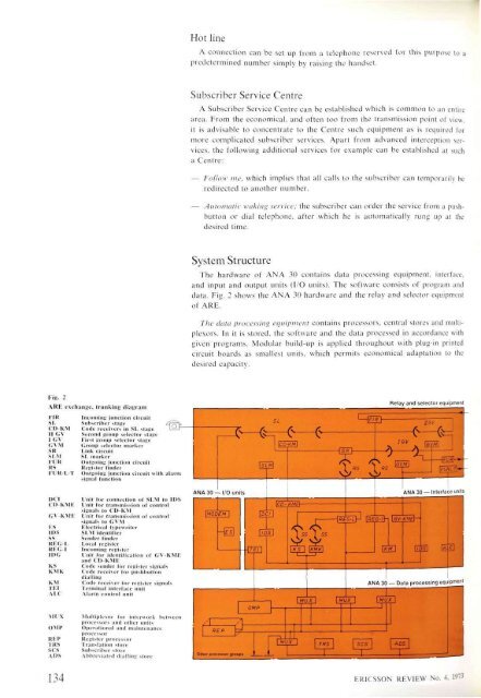
Fig. 2<br />
ARE exchange, (milking diagram<br />
FIR<br />
SL<br />
CD-KM<br />
II GV<br />
I GV<br />
GVM<br />
SR<br />
SLM<br />
FUR<br />
RS<br />
FLIR-L-T<br />
DO<br />
CD-KME<br />
ES<br />
IDS<br />
ss<br />
REG-I.<br />
REG-I<br />
IDG<br />
KS<br />
KMK<br />
KM<br />
TEI<br />
AIX<br />
MUX<br />
OMP<br />
REP<br />
TRS<br />
scs<br />
ADS<br />
134<br />
Incoming junction circuit<br />
Subscriber stage<br />
Code receivers in SL stage<br />
Second <strong>group</strong> selector stage<br />
First <strong>group</strong> selector stage<br />
Group selector marker<br />
Link circuit<br />
SL marker<br />
Outgoing junction circuit<br />
Register finder<br />
Outgoing junction circuit with alarm<br />
signal function<br />
L'nit for connection <strong>of</strong> SLM to IDS<br />
L'nit for transmission <strong>of</strong> control<br />
signals to CD-KM<br />
L'nit for transmission <strong>of</strong> control<br />
signals to GVM<br />
Electrical typewriter<br />
SLM identifier<br />
Sender finder<br />
Local register<br />
Incoming register<br />
I nit for identification <strong>of</strong> GV-KME<br />
and CD-KME<br />
Code sender for register signals<br />
Code receiver for pushbutton<br />
dialling<br />
Code receiver for register signals<br />
Terminal interface unit<br />
Alarm control unit<br />
Multiplexor for infcrwork between<br />
processors and o<strong>the</strong>r units<br />
Operational and maintenance<br />
processor<br />
Register processor<br />
Translation store<br />
Subscriber store<br />
Abbreviated dialling store<br />
Hot line<br />
A connection can be set up from a telephone reserved for this purpose to a<br />
predetermined number simply by raising <strong>the</strong> handset.<br />
Subscriber Service Centre<br />
A Subscriber Service Centre can be established which is common to an entire<br />
area. From <strong>the</strong> economical, and <strong>of</strong>ten too from <strong>the</strong> transmission point <strong>of</strong> view,<br />
it is advisable to concentrate to <strong>the</strong> Centre such equipment as is required for<br />
more complicated subscriber services. Apart from advanced interception services,<br />
<strong>the</strong> following additional services for example can be established at such<br />
a Centre:<br />
— Follow me, which implies that all calls to <strong>the</strong> subscriber can temporarily be<br />
redirected to ano<strong>the</strong>r number.<br />
— Automatic waking service; <strong>the</strong> subscriber can order <strong>the</strong> service from a pushbutton<br />
or dial telephone, after which he is automatically rung up at <strong>the</strong><br />
desired time.<br />
System Structure<br />
The hardware <strong>of</strong> ANA 30 contains data processing equipment, interface,<br />
and input and output units (I/O units). The s<strong>of</strong>tware consists <strong>of</strong> program and<br />
data. Fig. 2 shows <strong>the</strong> ANA 30 hardware and <strong>the</strong> relay and selector equipment<br />
<strong>of</strong> ARE.<br />
The data processing equipment contains processors, central stores and multiplexors.<br />
In it is stored, <strong>the</strong> s<strong>of</strong>tware and <strong>the</strong> data processed in accordance with<br />
given programs. Modular build-up is applied throughout with plug-in printed<br />
circuit boards as smallest units, which permits economical adaptation to <strong>the</strong><br />
desired capacity.<br />
ERICSSON REVIEW No. 4, 1973


