
You also want an ePaper? Increase the reach of your titles
YUMPU automatically turns print PDFs into web optimized ePapers that Google loves.
Pad printing machine<br />
<strong>TPX</strong> <strong>350</strong><br />
GB Operating instructions<br />
From machine-no. 800<br />
706 100 132 (<strong>TPX</strong> <strong>350</strong>-1 Englisch Version 1.0) 12.07.2002
Danger Warning for Machine Operation<br />
Settings, color and thinner adiition, as well as any working in the tampon free<br />
space may only be carried out when the machine is at rest.<br />
Hazardous Materials<br />
(Colors, Lacquers, Solvents, Leveling Agents, etc.)<br />
While handling hazardous materials to be used(colors, detergents, additives), the<br />
information of each respective safety data sheets must be paid attention to.<br />
Standard Tampon<br />
There is no risk of injury for the fingers while using standard tampons (tampon<br />
strength ≥ 35 to 40 mm) if used as intended.<br />
While using special tampons, tampon assembly, etc. additional protective measures<br />
must be carried out if required; i.e. two-hand switch, light barrier, loading and unloading<br />
equipment.<br />
<strong>Print</strong>ing matter intake<br />
<strong>Print</strong>ing Matter<br />
According to the kind / shape of the printing matter / printing matter intake, the risk of<br />
injury (jamming risk) between the printing matter / printing matter intake and the extending<br />
sword of the tampon cleaning changes.<br />
Additional protective measures must be carried out if required; i.e. two-hand switch,<br />
light barrier, loading and unloading equipment.<br />
Before casing sheets are taken off, the machine must be shut off and detached from<br />
the electricity network!
Index<br />
Technical data 4<br />
Dimension drawing 5<br />
Commissioning procedure 6<br />
Compressed air connection 6<br />
Magnetic disk used in combination 7<br />
Spatula and doctor blade 7<br />
Adjusting the doctor blade 8<br />
Switching point for the doctor blade tilt<br />
motion 8<br />
Regulating the doctor blade pressure 9<br />
Image pick-up 9<br />
Adjustment of the pad and the inking<br />
slide paths 10<br />
Speed setting 11<br />
Maintenance instructions 12<br />
Check on maintenance unit 13<br />
Cylinder with end-stop damping 13<br />
Power supply unit 14<br />
Nano-T control unit 15<br />
3<br />
I/O-Modul 16<br />
Exchanging the control unit Nano-T<br />
and the I/O module 17<br />
Initiator locations 18<br />
Incremental rotary tranducer fitting 19<br />
Emergency stop 20<br />
Contact allocation X4-X5, CAN-Bus,<br />
Foot switch 21<br />
Pad fastener 22<br />
Pneumatic diagram 23<br />
Pneumatic apparatus layout 24<br />
Control components and interface 25<br />
Wiring X4/X5 – I/O-Modul 26<br />
Power suplay 27<br />
Assignment of inputs of NANO-T<br />
control unit 28<br />
Assignment of outputs of NANO-T<br />
control unit 29<br />
Possible printing faults 30<br />
12.07.2002 <strong>TPX</strong> <strong>350</strong>-1 GB
Technical data<br />
Standard plate sizes: 100 x 100 mm 250 x 120 mm<br />
120 x 120 mm <strong>350</strong> x 120 mm<br />
160 x 120 mm<br />
1. Max. print image diameter: 80 mm resp. 100 mm<br />
2. <strong>Print</strong> capacity: Max. 1800 prints per hour<br />
3. Drive: Pneumatic Noise level: 66 - 69 dB (A)<br />
4. Compressed air connection: Working pressure 5-6 bar<br />
5. <strong>Print</strong>ing pressure: Max. 1680 N (168 kp) at 6 bar<br />
6. Air consumption: 1,3 l / cycle at 6 bar<br />
7. Electrical connection: 85 – 265 V, 47 – 63 Hz<br />
8. Control voltage: 24 V =<br />
9. Machine output impulse for No-volts contact<br />
automatic feed: Max. voltage 100 V / Max. rating 100 VA<br />
10. Control system: Process PLC with micro-processor and digital I/O module. In order<br />
to monitor the machine movement, contact-free switching initiators<br />
with LED are installed.<br />
11. Programming interface: RS232<br />
12. External interface: CAN-Bus<br />
13. Pad stroke: Infinitely variable, electronically<br />
14. Max. pad vertical stroke: 160 mm<br />
15. Max. pad throat depth: 158 mm<br />
16. Setting: Each working movement can be independently actuated by push<br />
button and mode-selector switch.<br />
17. Single cycle or continuous By push button<br />
operation:<br />
18. Cycle counter: Can be changed over to subtracting or performance display<br />
19. Speed setting: Infinitely variable, using flow regulators<br />
20. Weight: Bench model: approx: 160 kg<br />
21. Dimensions: Bench model: Width approx.: 462 mm<br />
Height: 818 mm<br />
Depth approx.: 1172 mm<br />
Subject to modification without notice.<br />
4<br />
<strong>TPX</strong> <strong>350</strong>-1 GB 26.07.2002
220<br />
SWITZERLAND<br />
Klischee max.<strong>350</strong><br />
ca. 442<br />
248<br />
max.<br />
107<br />
465<br />
500<br />
ca. 1172<br />
1035<br />
222<br />
43<br />
353<br />
120<br />
43<br />
min. 5<br />
190<br />
115<br />
27 27<br />
Empfohlene<br />
Druckhöhe<br />
120<br />
Hub max. 160 140 34 50 410<br />
20 798<br />
Technische Aenderungen vorbehalten<br />
We reserve the right to make any technical changes<br />
Sous reserve de modifications techniques<br />
Reservato el derecho de realizar modificaciones tecnicas<br />
Con riserva di mutazioni techniche<br />
<strong>TPX</strong> <strong>350</strong><br />
8240 THAYNGEN SWITZERLAND<br />
ERSETZT DURCH<br />
ERSATZ FUER<br />
GEZEICHN.<br />
GEPRUEFT<br />
706 435 002<br />
818<br />
<strong>TPX</strong> <strong>350</strong>-1<br />
25.04.02 TA<br />
INDEX<br />
A
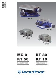
Commissioning procedure<br />
Compressed air connection<br />
Commissioning procedure<br />
1. Mains connection (1)<br />
Mains voltage according to data-plate on rear of<br />
machine<br />
2. Foot-switch connection (2)<br />
3. Socket for peripheral devices X4/X5 (3)<br />
Allocation see on page 21<br />
4. Programming interface PC RS 232 (9 Pol F)<br />
5. Connection Can Bus (15 Pol F)<br />
Compressed air connection<br />
1. Plug-in nippel G1/4“<br />
Legris, serie 22 matching: Aro 210<br />
Cejn 300<br />
Orion 44510<br />
Parker 50<br />
Rectus 14, 22<br />
Plug-in connection on the rear side of the pressure<br />
regulator for non-oiled, filtered air. 4/3 mm hose.<br />
2. Air pressure regulating valve Requi-<br />
red working pressure 5-6 bars<br />
3. Pressure gauge<br />
4. Sight glass filter<br />
5. Condensate drain pin<br />
To drain condensate, push pin upward<br />
6. Sight glass oiler<br />
7. Oil feed regulator screw<br />
6<br />
<strong>TPX</strong> <strong>350</strong>-1 GB 12.07.2002<br />
7<br />
6<br />
5<br />
4<br />
3<br />
2<br />
1<br />
open<br />
close<br />
De-oiled compressed air<br />
Thread M5 for plug nipple<br />
2<br />
1<br />
3<br />
4<br />
5
Magnetic disk used in combination<br />
Spatula and doctor blade<br />
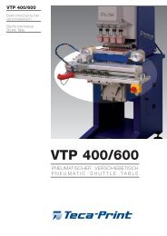
Magnetic disk used in combination<br />
Spatula and doctor blade<br />
Put spatula (1), with Art.-Nr. on the front<br />
of the sandwich plate (2).<br />
Fastening of blade holder (3) on the<br />
sandwich plate (2).<br />
Ideal space measurer – printing<br />
plate 1.5 to 2 mm.<br />
Check with Viscospatula (Art.-Nr.<br />
90 09 01).<br />
Space measurer-printing plate is adjustable on<br />
both sides (4) with spanner No. 4.<br />
7<br />
12.07.2002 <strong>TPX</strong> <strong>350</strong>-1 GB<br />
2<br />
1<br />
Article no.<br />
2<br />
3<br />
4
Adjusting the doctor blade<br />
Switching point for the doctor blade tilt<br />
motion<br />
The blade parallelism to the printing blade is<br />
set through the setting screws (6).<br />
The tilt motion of the blade<br />
The margin of the blade tilt motion is limited<br />
by the stop screws (7, 8) .<br />
Tilt motion upward (8)<br />
downward (7)<br />
Adjust front limit of inker slide travel with<br />
knurled screw (9).<br />
Ideal blade set down point 5 mm in front of<br />
the printing plate front edge.<br />
Switching point setting<br />
Doctor blade tilt on return<br />
The switching point of the initiator is altered<br />
by means of socket spanner no. 4. Ideal liftoff<br />
point 5 mm before the edge.<br />
1 spindle revolution = 1mm<br />
Important!<br />
If the speed of the inking slide (see 2, on<br />
page 11) is altered, the lift-off point also<br />
changes.<br />
8<br />
<strong>TPX</strong> <strong>350</strong>-1 GB 12.07.2002<br />
6<br />
7<br />
8<br />
5 mm<br />
9
Regulating the doctor blade pressure<br />
Image pick-up<br />
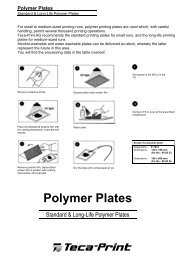
Regulating the doctor blade pressure<br />
The pressure of the doctor blade on the plate can<br />
be adjusted via the pressure regulating valve (12)<br />
and is readable on the pressure gauge (13)<br />
Image pick-up<br />
By sliding of the clamp (1) with pin spanner no. 4<br />
and by turning of the adjusting knob, the printing<br />
pad is centered over the plate for the printing<br />
image pick-up.<br />
9<br />
15.07.2002 <strong>TPX</strong> <strong>350</strong>-1 GB<br />
13<br />
12<br />
1
Adjustment of the pad and inking slide<br />
paths<br />
B<br />
A<br />
D<br />
10<br />
B A<br />
<strong>TPX</strong> <strong>350</strong>-1 GB 12.07.2002<br />
C<br />
Plate depth<br />
Image intake adjustable range ± 43 mm Pad slide at back = B<br />
Image delivery adjustable range ± 27 mm Pad slide at front = A<br />
Inking slide at front = C<br />
Inking slide at back = D<br />
120 mm<br />
150 mm special<br />
1 revolution 2 mm<br />
1 revolution 1,5 mm
Speed setting<br />
Speed setting<br />
1. Doctor blade tilt<br />
2. Ink application slide<br />
3. Pad slide<br />
4. Pad stroke<br />
Important: The speed must not<br />
be increased after<br />
adjustment.<br />
11<br />
1 2 3 4<br />
12.07.2002 <strong>TPX</strong> <strong>350</strong>-1 GB
Maintenance instructions<br />
Proximity initiators<br />
The response gap between the<br />
proximity initiators and the actuators<br />
should be set at 0.5 mm<br />
I1 Pad slide at rear<br />
I2 Pad slide at front<br />
I3 Inking slide at rear<br />
I4 Inking slide at front<br />
I5 Doctor blade tilt<br />
Incremental rotary transducer<br />
Monitoring of pad vertical stroke<br />
Pneumatic system<br />
Valve block<br />
1. Doctor blade tilt<br />
2. Inking slide<br />
3. Pad slide<br />
4. Pad vertical stroke<br />
5. Silencer<br />
I3<br />
(B33)<br />
12<br />
I5<br />
(B35)<br />
I4<br />
(B34)<br />
I1<br />
(B31)<br />
I2<br />
(B32)<br />
<strong>TPX</strong> <strong>350</strong>-1 GB 12.07.2002<br />
1<br />
2<br />
3 4 5
Check on conditioning unit<br />
Cylinder with end-stop damping<br />
Check on conditioning unit<br />
Oil feed regulator screw: Dose 5 drops per month.<br />
Oil: Hydraulic oil acc. to DIN 51 524 – HLP32<br />
Oil viscosity: 21-25 cSt bei 20°C.<br />
Too much oil leads to overoiling (slow cylinder).<br />
!<br />
Working pressure shown on gauge<br />
Europa = 6 bar<br />
USA / GB = 87 psi<br />
1 psi = 0,069 bar<br />
1 bar = 14,5 psi<br />
- After oiling tighten adjusting screw in<br />
clockwise direction.<br />
Cylinder with end-stop damping<br />
With very fine adjustment, excess oil may block<br />
end-stop damping. Check the end-stop<br />
13<br />
Screw-driver blade "0"<br />
close<br />
Adjusting screw<br />
18.07.2002 <strong>TPX</strong> <strong>350</strong>-1 GB<br />
open<br />
Push in condensate drain<br />
(Water) pin.<br />
Use intercepting tank.
Power supply unit<br />
Art. no.: 821 207 414<br />
Connections, LED (<strong>TPX</strong> <strong>350</strong> / 500)<br />
Output power 75 Watt<br />
Output current (24 V =) : 3,2 A<br />
Short-circuit proof<br />
LED green<br />
24 V =<br />
Gnd<br />
85 - 265 V<br />
47 - 63 Hz<br />
LED (green) → lights up, when the power unit is ready for operation.<br />
The LED goes out, when the power unit function is impaired.<br />
Possible causes are: - There is no primary voltage at the power unit input<br />
- The secondary load is too high and the power unit<br />
cuts off<br />
14<br />
<strong>TPX</strong> <strong>350</strong>-1 GB 18.07.2002
Nano-T control unit<br />
Incoming supply<br />
I/O module<br />
Gnd +24V<br />
-<br />
17<br />
47 48<br />
+<br />
18<br />
I/O-Board<br />
RUN<br />
RUN<br />
ERR<br />
Connection for<br />
PC (RS 232)<br />
Connection to<br />
keyboard<br />
I17<br />
I18<br />
15<br />
X5 PIN 7<br />
X5 PIN 9<br />
Battery<br />
Battery Kit Nano-T<br />
The service life of the battery is approx.<br />
10 years. Please only have the battery<br />
changed by specialised staff.<br />
Item. No. 821 206 107 (incl. Installation<br />
instructions)<br />
Connection for<br />
I/O-Modul<br />
12.07.2002 <strong>TPX</strong> <strong>350</strong>-1 GB
I/O-Modul<br />
CAN-Bus<br />
in (male)<br />
CAN-Bus<br />
out (female)<br />
(yellow) (red)<br />
from Nano-T<br />
24 V u. Gnd<br />
to Nano-T<br />
emergency<br />
stop<br />
(external)<br />
soft<br />
run-up<br />
16<br />
(signal contact)<br />
to external<br />
internal<br />
Logic 5V (yellow)<br />
ERROR (red)<br />
24 V Power supply (yellow)<br />
From power supply<br />
Emergency stopp switch<br />
(internal)<br />
Incremental<br />
encoder<br />
Encoder<br />
(LED yellow)<br />
<strong>TPX</strong> <strong>350</strong>-1 GB 12.07.2002<br />
Gnd 24 V
Exchanging the control unit Nano-T and the<br />
I/O module<br />
Recessed head screw<br />
1. Disconnect machine from power supply.<br />
2. Remove control box casing.<br />
3. Loosen plug-in connections and cables<br />
4. Undo fastening screws<br />
17<br />
Recessed head screw<br />
Control unit Nano-T<br />
I/O-Modul<br />
Important: When exchanging the control unit Nano-T please make sure<br />
that the same or latest software version is stored.<br />
When exchanging, always state software version and ID<br />
number.<br />
Software Version is on the rear side of the control box near<br />
the programming interface PC (RS232)<br />
If the sign at the programming interface PC (RS232) is missing, see system information in the manual Nano-T page 36<br />
12.07.2002 <strong>TPX</strong> <strong>350</strong>-1 GB
Initiator locations<br />
I3<br />
(B33)<br />
I5<br />
(B35)<br />
I4<br />
(B34)<br />
18<br />
I1<br />
(B31)<br />
Switching gap initiator 0.5 mm<br />
I2<br />
(B32)<br />
<strong>TPX</strong> <strong>350</strong>-1 GB 12.07.2002
Incremental rotary transducer fitting<br />
19<br />
703 502 314<br />
703 502 315<br />
M5 x 25<br />
M3 x 8<br />
801 004 511<br />
M4 x 10<br />
I/O-Modul<br />
A = blau, blue, bleu, azul, blu<br />
B = Schwarz, black, noire, negro, nero<br />
- = weiss, white, blanche, blanco, bianco<br />
+ = braun, brown, brun, marron, bruno<br />
703 502 023<br />
703 502 314<br />
703 502 315<br />
M3 x 8<br />
M5 x 25<br />
12.07.2002 <strong>TPX</strong> <strong>350</strong>-1 GB
Emergency stop<br />
Emergency<br />
stop valve<br />
+24 V/ Gnd<br />
for control unit<br />
and<br />
inputs/outputs<br />
Control unit<br />
power supply<br />
to Nano-T<br />
+ 24 V<br />
Emergency<br />
stop<br />
extension<br />
20<br />
Connections on PCB<br />
Emergency stop<br />
button<br />
Emergency stop<br />
printing machine<br />
<strong>TPX</strong> <strong>350</strong>-1 GB 12.07.2002<br />
Terminals<br />
I/O-modul<br />
see on page 16
Contact allocation<br />
X4 – X5, CAN-Bus, Foot switch<br />
Foot switch<br />
Start<br />
Stop tampon feed<br />
21<br />
Output impulse<br />
12.07.2002 <strong>TPX</strong> <strong>350</strong>-1 GB<br />
(Start)<br />
Output impulse<br />
Stop tampon feed
Klemmbride<br />
Dovetail adapter<br />
Collier de serrage<br />
35 12 63<br />
19.7<br />
48<br />
Tamponhalter zentrisch<br />
Pad holder centrical<br />
Support-tampon centrique<br />
35 25 62 H = 25<br />
35 30 62 H = 30<br />
35 40 62 H = 40<br />
35 50 62 H = 50<br />
35 60 62 H = 60<br />
35 70 62 H = 70<br />
<strong>TPX</strong> <strong>350</strong>/<strong>TPX</strong> 500<br />
120<br />
H<br />
B<br />
19.7<br />
<strong>TPX</strong><strong>350</strong> / <strong>TPX</strong> 500<br />
Tamponbefestigung<br />
Tamponhalteschine<br />
Pad mounting-rail<br />
Rail support du tampon<br />
A<br />
48<br />
8240 THAYNGEN SWITZERLAND<br />
50<br />
H<br />
<strong>TPX</strong> <strong>350</strong> 35 35 59<br />
<strong>TPX</strong> 500 704 502 320<br />
<strong>TPX</strong> 500/600 50 60 59<br />
Verschiebesupport<br />
Slide support<br />
Support culissant<br />
A B<br />
25 10 68 58 100<br />
25 20 68 58 90<br />
35 10 68 75 100<br />
Klemmbride<br />
Dovetail adapter<br />
Collier de serrage<br />
35 05 63<br />
Tamponkonus mit Überwurfmutter<br />
M16 x 1,5<br />
Pad cone with sleeve nut<br />
Cône pour support tampon avec écrou<br />
35 01 61<br />
Tamponhalter schmal<br />
Pad holder small<br />
Support-tampon étroit<br />
MSTB. GEZEI.<br />
%<br />
35 50 63 H = 50<br />
35 60 63 H = 60<br />
35 70 63 H = 70<br />
GEPR.<br />
706-535-003<br />
21.01.02 WE<br />
B
1.4<br />
1.0 2.0 3.0 4.0<br />
1.2 1.3 2.2 2.3 3.2 3.3 4.2 4.3<br />
Y54 (04)<br />
1.1<br />
Y52 (02) Y51 (01) Y53 (03) Y55 (05)<br />
2.1 3.1<br />
4.1 4.5<br />
7.1<br />
0.1<br />
5.0<br />
P<br />
Pneumatikschema<br />
Pneumatic-diagram<br />
Diagramme pneumatique<br />
Diagrama neumático<br />
Diagramma pneumatico<br />
8240 THAYNGEN BOHLSTRASSE 17<br />
<strong>TPX</strong> <strong>350</strong><br />
ERSETZT DURCH<br />
ERSATZ FUER<br />
GEZEICHN.<br />
GEPRUEFT<br />
706 735 006<br />
26.04.02 WE<br />
INDEX<br />
A
P<br />
1.1<br />
2.1<br />
3.1<br />
4.1 / 4.4<br />
1.2<br />
2.2<br />
3.2<br />
4.2<br />
1.3<br />
2.3<br />
3.3<br />
4.3<br />
0.1<br />
4.5<br />
2.0<br />
7.1<br />
1.4<br />
1.0<br />
3.0<br />
4.0<br />
Technische Aenderungen vorbehalten<br />
We reserve the right to make any technical changes<br />
Sous reserve de modifications techniques<br />
Reservato el derecho de realizar modificaciones tecnicas<br />
Con riserva di mutazioni techniche<br />
Lageplan<br />
Layout diagram<br />
Plan de masse<br />
Plano del conjunto<br />
Plano di deposito<br />
5.0<br />
8240 THAYNGEN SWITZERLAND<br />
<strong>TPX</strong> <strong>350</strong><br />
ERSETZT DURCH<br />
ERSATZ FUER<br />
GEZEICHN.<br />
GEPRUEFT<br />
706 735 007<br />
26.04.02 TA<br />
A<br />
INDEX
Display und<br />
Tastatur<br />
Display and<br />
keyboard<br />
Netzteil<br />
Power supply<br />
unit<br />
AC<br />
RS-422<br />
(1:1)<br />
Inkrementaldrehgeber<br />
Encoder<br />
interne<br />
Eingänge<br />
internal<br />
inputs<br />
interne<br />
Ausgänge<br />
internal<br />
outputs<br />
24V DC 24V DC<br />
interner Notaus<br />
internal emergency<br />
stop<br />
15-pol.<br />
24V DC<br />
24V DC<br />
CAN-Bus<br />
out<br />
CAN-Bus<br />
in<br />
I/ O -Modul<br />
oder Brücke<br />
(Klemme 11+12)<br />
or bridge<br />
(terminal 11+12)<br />
NANO-T<br />
I 101/<br />
I 102<br />
17/18<br />
Sanftanlaufventil<br />
soft-start valve<br />
oder Brücke<br />
(Klemme 1+3)<br />
or bridge<br />
(terminal 1+3)<br />
optional mit Kabelaustausch<br />
optional by changing cable<br />
9-pol.<br />
Maschinenrückwand<br />
machine back plate<br />
X4<br />
X4<br />
X5<br />
Fussschalter<br />
Foot swich<br />
optional (5 pol. Preh Buchse)<br />
optional (5 pol. Preh female)<br />
Netzeingang<br />
input power supply<br />
Technische Aenderungen vorbehalten<br />
We reserve the right to make any technical changes<br />
Sous reserve de modifications techniques<br />
Reservato el derecho de realizar modificaciones tecnicas<br />
Con riserva di mutazioni techniche<br />
Steuerungsrückwand<br />
PLC back plate<br />
Steuerungskomponenten<br />
und Schnittstellen<br />
Control components<br />
and interface<br />
8240 THAYNGEN SWITZERLAND<br />
RS 232 9 pol. Sub-D Buchse<br />
RS 232 9 pol. Sub-D female<br />
RS 485 (Jetway)<br />
15 pol. Sub-D Buchse<br />
RS 485 (Jetway)<br />
15 pol. Sub-D female<br />
CAN-Bus und 24V zu<br />
externer Peripherie<br />
mit I/O16-Modul<br />
15 pol. Sub-D Buchse<br />
CAN-Bus and 24V to<br />
external peripherie<br />
with I/O16-Modul<br />
15 pol. Sub-D female<br />
Notauserweiterung<br />
Emergency stop extension<br />
NANO-T<br />
ERSETZT DURCH<br />
ERSATZ FUER<br />
GEZEICHN.<br />
GEPRUEFT<br />
706 700 018<br />
23.04.02 WE<br />
INDEX
X5<br />
I1<br />
31<br />
I2<br />
Gnd<br />
I10<br />
1<br />
32<br />
14<br />
2<br />
1<br />
2<br />
I3<br />
REL NO<br />
O9<br />
33<br />
15<br />
4<br />
3<br />
I4<br />
REL C<br />
3<br />
34<br />
REL NC<br />
I11<br />
O15<br />
I15<br />
I7<br />
I8<br />
I12<br />
16<br />
6<br />
5<br />
4<br />
I5<br />
35<br />
17<br />
8<br />
7<br />
5<br />
I6<br />
36<br />
18<br />
10<br />
9<br />
I7<br />
6<br />
37<br />
19<br />
12<br />
11<br />
I8<br />
I17<br />
I14<br />
7<br />
38<br />
20<br />
14<br />
13<br />
I9<br />
I13<br />
I9<br />
I18<br />
I6<br />
I16<br />
O10<br />
O11<br />
O12<br />
O13<br />
O14<br />
+24V<br />
8<br />
39<br />
21<br />
16<br />
15<br />
I10<br />
9<br />
40<br />
22<br />
18<br />
17<br />
I11<br />
10<br />
23<br />
20<br />
19<br />
I12<br />
11<br />
24<br />
22<br />
21<br />
I13<br />
12<br />
25<br />
24<br />
23<br />
I14<br />
13<br />
26<br />
25<br />
I15<br />
I16<br />
X4<br />
47<br />
I17<br />
1<br />
I18<br />
48<br />
Gnd<br />
1<br />
2<br />
6<br />
REL NO<br />
2<br />
O1<br />
REL C<br />
3<br />
4<br />
7<br />
51<br />
REL NC<br />
3<br />
O2 I11<br />
5<br />
6<br />
8<br />
52<br />
O15<br />
4<br />
O3<br />
I12<br />
7<br />
8<br />
9<br />
53<br />
O11<br />
5<br />
O4<br />
+24V<br />
9<br />
10<br />
54<br />
O5<br />
X4<br />
55<br />
Gnd<br />
REL NO<br />
REL C<br />
REL NC<br />
I11<br />
O15<br />
I12<br />
O11<br />
+24V<br />
1<br />
O6<br />
6<br />
56<br />
2<br />
O7<br />
7<br />
FS<br />
57<br />
3<br />
O8<br />
4<br />
8<br />
58<br />
3<br />
4<br />
2<br />
O9<br />
9<br />
1<br />
59<br />
5<br />
O10<br />
O11<br />
CAN-BUS<br />
Belegung des<br />
CAN-Bus-Steckers<br />
Pin 1-9 nach Jetter-<br />
Standard<br />
14<br />
12<br />
A2<br />
O12<br />
Technische Aenderungen vorbehalten<br />
We reserve the right to make any technical changes<br />
Sous reserve de modifications techniques<br />
Reservato el derecho de realizar modificaciones tecnicas<br />
Con riserva di mutazioni techniche<br />
1<br />
A1<br />
9<br />
11<br />
O13<br />
2<br />
10<br />
Gnd<br />
O14<br />
3<br />
11<br />
connection of<br />
CAN-Bus-plug<br />
Pin 1-9 like Jetter-<br />
Standard<br />
O15<br />
Gnd<br />
4<br />
Verdrahtung<br />
X4/X5 - I/O-Modul<br />
Wiring<br />
X4/X5 - I/O-Modul<br />
Gnd<br />
12<br />
O16<br />
5<br />
+24V<br />
13<br />
24V für Ausgänge und Logik<br />
24V for outputs and logic<br />
8240 THAYNGEN SWITZERLAND<br />
6<br />
4<br />
1<br />
B<br />
A<br />
Kanal<br />
channel<br />
+24V<br />
14<br />
7<br />
24<br />
+<br />
+<br />
21<br />
11<br />
5<br />
2<br />
von Netzteil<br />
from power<br />
supply unit<br />
+24V<br />
+24V<br />
15<br />
8<br />
Gnd<br />
-<br />
-<br />
-<br />
22<br />
12<br />
3<br />
NANO-T<br />
+ -<br />
GND<br />
24V u. Gnd<br />
an NANO-T<br />
to NANO-T<br />
Inkrementaldrehgeber<br />
Encoder<br />
ERSETZT DURCH<br />
ERSATZ FUER<br />
GEZEICHN.<br />
GEPRUEFT<br />
706 700 020<br />
Sanftanlaufventil<br />
Soft start valve<br />
Notaus-Schalter<br />
Emergency<br />
stop button<br />
Notaus-Erweiterung<br />
Emergency<br />
stop extension<br />
23.04.02 WE<br />
INDEX
S1.0<br />
L1<br />
PE N<br />
230V/50Hz<br />
58265 0002<br />
821 203 037<br />
821 207 424<br />
S1.3<br />
821 209 671<br />
1 2<br />
3<br />
110V<br />
230V<br />
L1.3<br />
4<br />
optional<br />
110 V<br />
821 209 265<br />
N<br />
<strong>TPX</strong><strong>350</strong>/500<br />
230V<br />
FG<br />
24V<br />
820 207 414<br />
L +<br />
-<br />
24 V<br />
OV<br />
I/O-module<br />
Technische Aenderungen vorbehalten<br />
We reserve the right to make any technical changes<br />
Sous reserve de modifications techniques<br />
Reservato el derecho de realizar modificaciones tecnicas<br />
Con riserva di mutazioni techniche<br />
Spannungsversorgung<br />
Power suplay<br />
8240 THAYNGEN SWITZERLAND<br />
NANO-T<br />
703 008 102<br />
ERSETZT DURCH<br />
ERSATZ FUER<br />
GEZEICHN.<br />
GEPRUEFT<br />
706 700 019<br />
23.04.02 WE<br />
INDEX
Assignment of inputs of NANO-T<br />
control unit<br />
Inputs used internally<br />
I1 (E201) Pad slide rear<br />
I2 (E202) Pad slide forward<br />
I3 (E203) Inking unit rear<br />
I4 (E204) Inking unit forward<br />
I5 (E205) Raise cutter / pressure switch by pot machine<br />
Inputs for use internally and/or on X5<br />
I6 (E206) Pin 22 Safety door switch / TFC indexing down<br />
I7 (E207) Pin 18 TFC single step<br />
I8 (E208) Pin 6 TFC On-Off<br />
I9 (E301) Pin 21 TFC indexing up<br />
Inputs used internally and on X5<br />
I10 (E302) Pin 14 Machine start<br />
Inputs used on X5<br />
I11 (E303) Pin 4 Stop continuous running / no fault cleaning tape (only in PLC mode)<br />
I12 (E304) Pin 19 Stop pad stroke<br />
Inputs for use on X5 only<br />
I13 (E305) Pin 8 Pad cleaning forward<br />
I14 (E306) Pin 20 Pad cleaning rear<br />
I15 (E307) Pin 5 PLC stop TP-slide back / RT advance rear / VTP in position / Set-up TFC<br />
I16 (E308) Pin 10 TFC advance forward<br />
I17 (E101) Pin 7 ext. start TAC / Ejector rear<br />
I18 (E102) Pin 9 Unlock TFC<br />
28<br />
<strong>TPX</strong> <strong>350</strong>-1 GB 12.07.2002
Assignment of outputs of NANO-T<br />
control unit<br />
Outputs used internally<br />
O1 (A201) Pad slide<br />
O2 (A202) Inking unit slide<br />
O3 (A203) Pad stroke<br />
O4 (A204) Cutter<br />
O5 (A205) Slow motion<br />
Outputs for internal use<br />
O6 (A206) Pad cleaning<br />
O7 (A207) Pad shift<br />
O8 (A208) Height equalization<br />
Outputs for use internally and/ or on X5<br />
O9 (A301) Pin 2 Ejector / latch if <strong>TPX</strong> 460 K<br />
Outputs for use on X5 only<br />
O10 (A302) Pin 23 PLC Busy / RT advance / VTP to right<br />
O11 (A303) Pin 11 PLC pad slide in motion / VTP to left<br />
O12 (A304) Pin 24 Unlock VTP latch<br />
O13 (A305) Pin 12 TFC indexing high<br />
O14 (A306) Pin 25 TFC advance<br />
Outputs used on X5<br />
O15 (A307) Pin 17 Output pulse (signal) / clock TFC<br />
O16 (A308) Relay Pin 3 C/ Pin 15 NO/ Pin 16 NC (cleaning motor)<br />
29<br />
12.07.2002 <strong>TPX</strong> <strong>350</strong>-1 GB
Possible printing faults<br />
The pad can only yield as good a pattern as it has picked up.<br />
If faults occur, make the following checks first:<br />
• Is the plate saturated with ink?<br />
• Check the ink pick-up on the pad (with mirror).<br />
Fault Cause Remedy<br />
Holes in print<br />
Splashes<br />
Clouds<br />
Distortion<br />
Too little ink =<br />
insufficient opacity<br />
Ink distribution nonuniform<br />
Contours not clear-cut<br />
• Air bubbles on ink pick-up.<br />
• Ink is too thin.<br />
• Pad is too flat.<br />
• Pad down-stroke too fast; hence too high a<br />
roll-over speed of pad print surface.<br />
• If the pad is splashed, this happens when the<br />
pad retracts from the plate.<br />
Reason:<br />
• Some of the deformation energy is<br />
converted to a static charging of the pad<br />
and the ink.<br />
• Occurs frequently in wide-area print zones<br />
(pad float), especially when printing non-flat<br />
surfaces; e.g. cylinders, cones.<br />
• <strong>Print</strong> surface has low points or high points, or<br />
is smaller than the pad area.<br />
• <strong>Print</strong> on non-plane surface is always<br />
distorted.<br />
• Ink too thick (viscosity).<br />
• Pad not yet activated.<br />
• Inadequate plate depth, or ink clotted.<br />
• Machine cycle time is too long or too<br />
irregular.<br />
• Pad retains too much ink.<br />
• Plate or film do not sound.<br />
Depth of etch irregular.<br />
• Plate part-clogged with ink.<br />
• Ink is crushed by the pad.<br />
• Pad stroke too short..<br />
• Ink is too thick. (Saturation fault).<br />
• Too little ink.<br />
• Ink is too thin. Ink is crushed.<br />
• Cycle time is too long or too irregular.<br />
• Pad stroke too short.<br />
• Retarder used.<br />
• Possibily too great an etching depth<br />
> 30 microns.<br />
30<br />
• Adjust for thicker ink.<br />
• Take steeper pad.<br />
• Reduce speed of pad down-stroke.<br />
• Check the pad after ink take-up (mirror).<br />
• Adjust for thinner ink.<br />
• Use a softer pad.<br />
• Fit an ionizing rod in front of the plate.<br />
• Fill the low points, expand the pad roll<br />
surface.<br />
• Special measures are necessary.<br />
• Fill the low points, expand the pad roll<br />
surface.<br />
• Special measures are necessary.<br />
• Thin the ink.<br />
• Activate pad with thinner.<br />
• Check the plate and clean if necessary.<br />
• Reduce machine cycle time. Work with<br />
automatic control. Check work bench layout.<br />
• Blow cold air on pad, or prolong time<br />
between ink take-up and deposit.<br />
(Do not use retarder).<br />
• Check the film.<br />
• Clean the plate.<br />
• Set for thicker ink.<br />
• Correct pad stroke.<br />
• Check saturation.<br />
• Top up with ink; mix well.<br />
• Set for thicker ink.<br />
• Keep to cycle time.<br />
• Correct pad stroke.<br />
• Work without retarder.<br />
• New plate. Etching depth for steel plate:<br />
Normal 22 microns, for fine marks 16<br />
microns.<br />
• Use plastic screen film E 7812.<br />
<strong>TPX</strong> <strong>350</strong>-1 GB 12.07.2002