View datasheet (PDF) - TecQuipment Ltd
View datasheet (PDF) - TecQuipment Ltd
View datasheet (PDF) - TecQuipment Ltd

You also want an ePaper? Increase the reach of your titles
YUMPU automatically turns print PDFs into web optimized ePapers that Google loves.
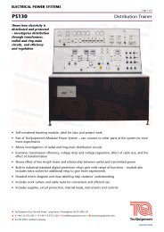
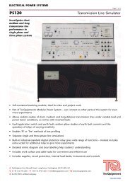
ELECTRICAL POWER SYSTEMS<br />
PS100 Salient Pole Generator<br />
Provides typical<br />
generator performance<br />
characteristics for<br />
experiments in<br />
generation,<br />
synchronising and<br />
paralleling, and load<br />
sharing<br />
• Self-contained teaching module – ideal for class and project work<br />
Generator and prime mover included in the base of the control console<br />
Includes supplies, circuit protection, internal load banks, instruments and controls<br />
Simulated power transmission line for realistic tests<br />
Synchronising by synchroscope and three-lamp method<br />
Built-in industrial-standard digital protection relay gives wide range of functions – module also<br />
includes extra socket for additional relay to give even more experiments<br />
• <strong>TecQuipment</strong> <strong>Ltd</strong>, Bonsall Street, Long Eaton, Nottingham NG10 2AN, UK<br />
T +44 115 972 2611 F +44 115 973 1520 E info@tecquipment.com W www.tecquipment.com<br />
An ISO 9001 certified company<br />
Page 1 of 3<br />
Part of <strong>TecQuipment</strong>’s Modular Power System range – can connect to other parts of the system for<br />
even more experiments<br />
Manual or automatic generator excitation<br />
Detailed mimic diagram and clear labelling to help students’ understanding<br />
Includes work surface and cable racks for convenient and efficient use<br />
AW/DB/0610
ELECTRICAL POWER SYSTEMS<br />
PS100 Salient Pole Generator<br />
Description<br />
Part of the Modular Power System range, the Salient Pole<br />
Generator explores the principles and characteristics of<br />
salient pole generators.<br />
The module contains everything needed for salient pole<br />
generator experiments including resistive, capacitive and<br />
inductive load banks. The open and flexible design is ideal<br />
for lecturers to create their own experiments, as well as<br />
student project work.<br />
To allow realistic investigations, the characteristics of the<br />
prime mover and generator are similar to industrial turbine<br />
and generator sets.<br />
For protection tests, current transformers (CTs) in the test<br />
circuits connect to the protection relay fitted to the upper<br />
control panel.<br />
The user connects and sets the protection relay to detect<br />
line and earth currents, voltage and frequency faults. The<br />
relay also monitors and measures fault events and<br />
disturbances for fault analysis. The user sets the relay from<br />
its local control panel, or by a cable link to a suitable<br />
computer (computer not included) and software (included).<br />
When the user applies a circuit fault, the relay opens circuitbreakers<br />
in the test circuits. The circuit-breakers also include<br />
hand-operated switches and lamps. The lamps show<br />
whether the circuit-breakers are open or closed.<br />
The control and protection circuits work when the<br />
generator is unsynchronised and synchronised to the<br />
mains electrical supply. When the generator is<br />
synchronised, the user can operate a variable quadrature<br />
droop for reactive power regulation.<br />
The prime mover and generator set is two coupled<br />
machines mounted on a common bedplate in the base of<br />
the control console. Manual or automatic voltage<br />
regulation (AVR) excitation controls the output voltage of<br />
the generator. When the generator is in overrun mode,<br />
resistors dissipate the reverse power. A vector drive controls<br />
the speed of the prime mover and allows investigations into<br />
load flow in positive and negative directions. An integral<br />
shaft encoder allows load angle analysis.<br />
Transducers with BNC connections allow voltage and<br />
current waveform measurement, display and analysis using<br />
an external oscilloscope (not supplied).<br />
For more experiments in protection, the unit has an extra<br />
socket to connect an additional protection relay (available<br />
separately).<br />
Supplied with the equipment is a set of shrouded leads for<br />
the user to connect the test circuits together.<br />
The unit includes an emergency switch, a mains supply<br />
isolator and protection fuses.<br />
A set of sockets links the module to other parts of<br />
<strong>TecQuipment</strong>’s Modular Power System (available<br />
separately). The Modular Power System allows experiments<br />
on power generation, transformation, transmission,<br />
distribution, utilisation and protection.<br />
<strong>TecQuipment</strong> <strong>Ltd</strong>, Bonsall Street, Long Eaton, Nottingham NG10 2AN, UK<br />
T +44 115 972 2611 F +44 115 973 1520 E info@tecquipment.com W www.tecquipment.com<br />
An ISO 9001 certified company<br />
Page 2 of 3<br />
Standard Features<br />
Supplied with comprehensive user guide<br />
Two-year warranty<br />
Manufactured in accordance with the latest European<br />
Union directives<br />
Experiments<br />
A.C. generator output voltage and frequency control<br />
Voltage, speed and field current characteristics<br />
Generator open-circuit test<br />
Short-circuit test<br />
Non-inductive load test<br />
Normal and sudden short-circuit tests<br />
Zero-power factor test<br />
Synchronising and parallelling<br />
Control of real and reactive power<br />
Protective relays<br />
Extra experiments when used with the other parts of the<br />
Modular Power System:<br />
Transformation<br />
Transmission<br />
Distribution<br />
Utilisation and protection<br />
Recommended Ancillaries<br />
Power Factor Load Bank (PS230)<br />
Oscilloscope (OS2)<br />
Additional relays:<br />
Overcurrent and Earth Fault Relay (PS251)<br />
Differential Protection Relay (PS252)<br />
Directional/Non-directional Overcurrent Relay (PS253)<br />
Feeder Management Relay (PS254)<br />
Other Modular Power System units:<br />
One or more of the other units in the Modular<br />
Power System range:<br />
Transformer Trainer (PS110)<br />
Transmission Line Simulator (PS120)<br />
Distribution Trainer (PS130)<br />
Switched Busbar Module (PS150)<br />
Also, to help connect two or more units of the<br />
Modular Power System, <strong>TecQuipment</strong> recommends that<br />
you use the Modular Power System Hub (PS160).
ELECTRICAL POWER SYSTEMS<br />
PS100 Salient Pole Generator<br />
The Modular Power System<br />
Salient Pole<br />
Generator<br />
(PS100)<br />
Essential Services<br />
The module can connect directly to an electrical supply as<br />
a stand-alone unit, or it can be powered from the optional<br />
PS160 Hub.<br />
Electrical supply (stand-alone):<br />
Three-phase 400 V, 16 A, 50 Hz<br />
or 220 V, 60 Hz (specify on order)<br />
Electrical supply (for the PS160 Hub):<br />
Three-phase 380/415 V, 32 A, 50 Hz or 60 Hz (specify on<br />
order)<br />
Floor space needed:<br />
Approximately 3 m x 2 m of solid, level floor<br />
Operating Conditions<br />
Operating environment:<br />
Well ventilated laboratory environment<br />
Storage temperature range:<br />
–25°C to +55°C (when packed for transport)<br />
Operating temperature range:<br />
+5°C to +40°C<br />
Operating relative humidity range:<br />
80% at temperatures < 31°C decreasing linearly to 50% at<br />
40°C<br />
Sound Levels<br />
Less than 70 db(A)<br />
Electrical supply<br />
<strong>TecQuipment</strong> <strong>Ltd</strong>, Bonsall Street, Long Eaton, Nottingham NG10 2AN, UK<br />
T +44 115 972 2611 F +44 115 973 1520 E info@tecquipment.com W www.tecquipment.com<br />
An ISO 9001 certified company<br />
Transformer<br />
Trainer<br />
(PS110)<br />
HUB<br />
(PS160)<br />
Transmission Line<br />
Simulator<br />
(PS120)<br />
Specifications<br />
Distribution<br />
Trainer<br />
(PS130)<br />
Switched Busbar<br />
Module<br />
(PS150)<br />
Page 3 of 3<br />
Nett dimensions and weight:<br />
1850 mm x 1870 mm x 960 mm and 750 kg<br />
Packed volume and weight:<br />
5.0 m3 and 1050 kg<br />
Generator:<br />
6.5 kVA maximum (operated at a nominal 2 kVA), 0.8 pf,<br />
four-pole, three-phase salient pole a.c. generator. 50 Hz,<br />
1500 rev.min –1 and 60 Hz, 1800 rev.min –1. Automatic<br />
voltage regulator (AVR) or manually excited.<br />
Prime mover:<br />
7.5 kW, four-pole, three-phase induction motor. Includes a<br />
shaft encoder and cooling fan. Driven by a four-quadrant<br />
a.c. vector drive.<br />
Instruments:<br />
Prime mover power and speed<br />
Multi-function meter for a.c. measurements (voltage,<br />
current, power factor, power, VAr and VA)<br />
Load angle meter<br />
Generator excitation voltage and current<br />
Synchroscope and three lamps<br />
Incoming running voltage and frequency