Power System Simulator - TecQuipment Ltd
Power System Simulator - TecQuipment Ltd
Power System Simulator - TecQuipment Ltd

You also want an ePaper? Increase the reach of your titles
YUMPU automatically turns print PDFs into web optimized ePapers that Google loves.
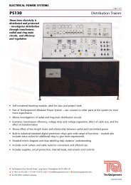
ELECTRICAL POWER SYSTEMS<br />
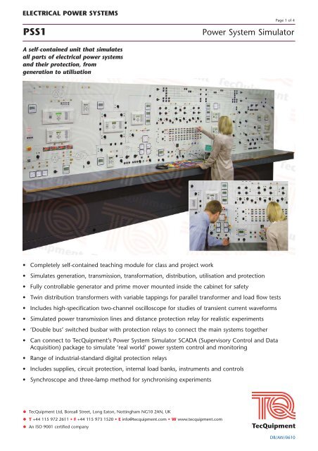
PSS1 <strong>Power</strong> <strong>System</strong> <strong>Simulator</strong><br />
A self-contained unit that simulates<br />
all parts of electrical power systems<br />
and their protection, from<br />
generation to utilisation<br />
• Completely self-contained teaching module for class and project work<br />
Simulates generation, transmission, transformation, distribution, utilisation and protection<br />
Fully controllable generator and prime mover mounted inside the cabinet for safety<br />
Twin distribution transformers with variable tappings for parallel transformer and load flow tests<br />
Includes high-specification two-channel oscilloscope for studies of transient current waveforms<br />
Simulated power transmission lines and distance protection relay for realistic experiments<br />
‘Double bus’ switched busbar with protection relays to connect the main systems together<br />
Can connect to <strong>TecQuipment</strong>’s <strong>Power</strong> <strong>System</strong> <strong>Simulator</strong> SCADA (Supervisory Control and Data<br />
Acquisition) package to simulate ‘real world’ power system control and monitoring<br />
Range of industrial-standard digital protection relays<br />
Includes supplies, circuit protection, internal load banks, instruments and controls<br />
Synchroscope and three-lamp method for synchronising experiments<br />
• <strong>TecQuipment</strong> <strong>Ltd</strong>, Bonsall Street, Long Eaton, Nottingham NG10 2AN, UK<br />
T +44 115 972 2611 F +44 115 973 1520 E info@tecquipment.com W www.tecquipment.com<br />
An ISO 9001 certified company<br />
Page 1 of 4<br />
DB/AW/0610
ELECTRICAL POWER SYSTEMS<br />
PSS1 <strong>Power</strong> <strong>System</strong> <strong>Simulator</strong><br />
Description<br />
The <strong>Power</strong> <strong>System</strong> <strong>Simulator</strong> contains everything needed<br />
to teach students how electrical power systems work.<br />
It is a self-contained unit (only needs electrical power) with<br />
full safety features. It includes all the main parts of an<br />
electrical power system, from supply (generation) to<br />
demand (utilisation). Each part includes dedicated<br />
industrial-standard protection relays that do specific jobs,<br />
from generator protection to distance protection on<br />
transmission lines, and distribution transformer protection.<br />
Generator and grid supply<br />
The PSS1 has a motor (prime mover) and generator set to<br />
simulate power generation. This set has characteristics<br />
similar to industrial turbine and generator sets for realistic<br />
experiments. The output of the generator passes through a<br />
generator transformer to a ‘generator bus’. Protection<br />
relays and contact breakers monitor and switch the<br />
generator field and output.<br />
The PSS1 includes a fully monitored and protected grid<br />
supply transformer. This transformer simulates the larger<br />
grid transformers used in national grid supply systems. The<br />
grid transformer reduces the incoming mains supply to<br />
give the correct distribution voltage at the ‘grid bus’. It<br />
also allows students to correctly synchronise the generator<br />
output to the grid supply. For realistic tests, students can<br />
use the grid supply or the generator as a power source for<br />
their experiments.<br />
Transmission lines<br />
A set of reactances simulate transmission lines of different<br />
lengths to simulate overhead or underground power<br />
cables. Each line includes test points to monitor the<br />
conditions along the lines. The user can simulate faults at<br />
different places along the transmission lines and discover<br />
the effects. A dedicated distance protection relay protects<br />
the lines and can indicate how far along the line the fault<br />
has occurred.<br />
Transformation, distribution and utilisation<br />
As well as the grid supply and generator transformers, the<br />
<strong>Power</strong> <strong>System</strong> <strong>Simulator</strong> has two identical distribution<br />
transformers to simulate the distribution transformers fitted<br />
near to factories or houses. These transformers have<br />
variable tappings and feed a ‘utilisation bus’. Dedicated<br />
relays protect the transformers and can work in different<br />
ways, determined by student experiments. The utilisation<br />
bus simulates electrical consumers (houses and factories). It<br />
includes variable resistive, capacitive and inductive loads,<br />
with an induction motor (dynamic) load.<br />
A switched busbar section includes a main bus and a<br />
standby or ‘reserve bus’. These simulate a real busswitching<br />
system in a power plant or power distribution<br />
station. Protection relays and contact breakers monitor and<br />
switch the incoming and outgoing feeders of the busbar.<br />
One feeder of the busbar has a ‘point-on-wave’ circuitbreaker<br />
for studies of switching transients.<br />
<strong>TecQuipment</strong> <strong>Ltd</strong>, Bonsall Street, Long Eaton, Nottingham NG10 2AN, UK<br />
T +44 115 972 2611 F +44 115 973 1520 E info@tecquipment.com W www.tecquipment.com<br />
An ISO 9001 certified company<br />
Page 2 of 4<br />
Test points, transducers and fault switches<br />
All the important circuits have test points connected to a<br />
set of test sockets. The students can link out these sockets<br />
or connect them to other test equipment. A set of<br />
transducers allows students to connect the test sockets to<br />
an oscilloscope (supplied) for transient measurements.<br />
There are two fault switches to apply faults to different<br />
parts of the <strong>Power</strong> <strong>System</strong> <strong>Simulator</strong>. One fault switch is a<br />
standard three-phase switch; the other is a timed circuit<br />
breaker with a digital timer to set a precise fault duration.<br />
Protection relays and instruments<br />
All parts of the PSS1 include industrial-standard protection<br />
relays. The relays show students how actual power systems<br />
are protected and the different ways that they are<br />
protected. The students can set the relays from their<br />
control panels. The more complex relays also include<br />
sockets to link them to a suitable computer (computer not<br />
included) for more detailed programming, if needed. The<br />
relays operate the circuit-breakers around the PSS1. The<br />
circuit-breakers also include hand-operated switches, and<br />
lamps. The lamps show whether the circuit-breaker is open<br />
or closed.<br />
Multi-function digital meters connect to all the important<br />
circuits to show the conditions of all three phases. A phaseangle<br />
meter shows the phase difference between any two<br />
voltages connected to it.<br />
Moving coil meters show the prime mover voltage, current<br />
and power.<br />
Standard Features<br />
Supplied with comprehensive user guide<br />
Two-year warranty<br />
Made in accordance with the latest European Union<br />
directives
ELECTRICAL POWER SYSTEMS<br />
PSS1 <strong>Power</strong> <strong>System</strong> <strong>Simulator</strong><br />
Experiments<br />
Transmission, distribution and utilisation:<br />
Load flow<br />
Symmetrical faults<br />
Unbalanced faults<br />
Unsymmetrical faults<br />
Circuit interruption<br />
Generator:<br />
Synchronisation<br />
Characteristics and performance<br />
Voltage variation and control<br />
Voltage regulation<br />
Stability studies<br />
Transformer:<br />
Unequal taps<br />
Unequal impedances<br />
Unbalanced loads<br />
Overcurrent protection:<br />
Relay grading<br />
Auto-reclose<br />
High-set instantaneous<br />
Back-tripping<br />
Directional control<br />
General protection:<br />
Phase faults<br />
Earth faults<br />
Distance protection<br />
Differential protection of transformers<br />
Differential protection of generators<br />
Busbar protection<br />
Generator protection<br />
<strong>TecQuipment</strong> <strong>Ltd</strong>, Bonsall Street, Long Eaton, Nottingham NG10 2AN, UK<br />
T +44 115 972 2611 F +44 115 973 1520 E info@tecquipment.com W www.tecquipment.com<br />
An ISO 9001 certified company<br />
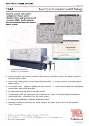
Recommended Ancillaries<br />
Page 3 of 4<br />
<strong>Power</strong> <strong>System</strong> <strong>Simulator</strong> SCADA Package (PSS2)<br />
(*SCADA = Supervisory Control and Data Acquisition)<br />
This is a computer, a printer and communications<br />
hardware, with industrial-standard software that<br />
communicates with the relays and other instruments of<br />
the <strong>Power</strong> <strong>System</strong> <strong>Simulator</strong>. It allows students to<br />
remotely monitor and control the different parts of the<br />
PSS1.<br />
Second Generator (PSS3)<br />
This is a console that contains a duplicate of the prime<br />
mover and generator fitted in the PSS1, but includes<br />
added features and protection relays for extra<br />
experiments in embedded and central generation.<br />
Note: the Second Generator is only for use with the<br />
<strong>Power</strong> <strong>System</strong> <strong>Simulator</strong>. It does not work as a standalone<br />
product.<br />
Essential Services<br />
Electrical supply:<br />
Three-phase 10 kW, 50 or 60 Hz (specify on order)<br />
Floor space needed:<br />
Approximately 6 m x 3 m of solid, level floor<br />
Operating Conditions<br />
Operating environment:<br />
Laboratory environment<br />
Storage temperature range:<br />
–25ºC to +55ºC (when packed for transport)<br />
Operating temperature range:<br />
+5ºC to +40ºC<br />
Operating relative humidity range:<br />
80% at temperatures < 31ºC decreasing linearly to 50% at<br />
40ºC<br />
Sound Levels<br />
Less than 70 dB(A)
ELECTRICAL POWER SYSTEMS<br />
PSS1 <strong>Power</strong> <strong>System</strong> <strong>Simulator</strong><br />
Specification<br />
Nett dimensions:<br />
5100 mm long (plus an additional 500 mm to the right of<br />
the cabinet for power connections).<br />
1500 mm front to back (plus an additional 1.5 m at the<br />
back when the access doors are open)<br />
2000 mm high<br />
2860 kg nett weight<br />
Packed volume and weight:<br />
21.74 m3 and 3530 kg<br />
<strong>Simulator</strong> voltages:<br />
Distribution: 220 V three-phase line to line<br />
Utilisation: 110 V three-phase line to line<br />
Grid transformer:<br />
5 kVA delta to star (Dy11)<br />
Primary is matched to the incoming three-phase supply<br />
to give the 220 V three-phase line-to-line secondary<br />
distribution voltage. Includes earth link for the<br />
secondary star point and a selectable tapping earth<br />
resistor for restricted earth fault protection tests.<br />
Generator and prime mover:<br />
6 kVA maximum (operated at a nominal 2 kVA), fourpole<br />
salient pole a.c generator<br />
Brushless, with automatic and manual excitation.<br />
7 kVA maximum induction motor with shaft encoder<br />
and electronic four-quadrant a.c vector-drive control,<br />
with a four-position drive inertia switch<br />
Generator transformer:<br />
1:1 ratio delta-to-star (Dy11) impedance matching with<br />
adjustable secondary tapping<br />
Transmission lines:<br />
Line reactances simulate ‘per unit’ (pu) values of<br />
impedance:<br />
Line 1: 0.10 pu<br />
Lines 2 and 3: 0.15 pu<br />
Lines 4 and 5: 0.25 pu<br />
Line 6: 5 x 0.1 pu length with four test points and<br />
<strong>TecQuipment</strong> <strong>Ltd</strong>, Bonsall Street, Long Eaton, Nottingham NG10 2AN, UK<br />
T +44 115 972 2611 F +44 115 973 1520 E info@tecquipment.com W www.tecquipment.com<br />
An ISO 9001 certified company<br />
Page 4 of 4<br />
dedicated three-zone distance protection<br />
Line 7: 4 x 0.01 pu (cable)<br />
Capacitors are provided adjacent to the lines. Each<br />
capacitor has selectable values and may be inserted in<br />
circuit to give π or T-line configurations for studies of<br />
losses.<br />
Distribution transformers:<br />
Two identical 2 kVA transformers, 220 V to 110 V<br />
Star-to-delta Yd1<br />
Adjustable primary tappings and matched impedances<br />
Switched busbar:<br />
Six bi-directional feeders, each with circuit-breakers –<br />
one circuit breaker is a ‘point-on-wave’ device<br />
Two circuit-breakers to break each half of each bus<br />
Twelve bus isolators, six on each half of the bus<br />
Two circuit-breakers that break the coupling between<br />
the main and reserve bus<br />
Protection relays:<br />
Grid transformer protection<br />
Grid bus protection<br />
Generator protection<br />
Generator bus protection<br />
Distance protection<br />
2 x double bus protection<br />
4 x distribution transformer protection<br />
Loads:<br />
Two separate 220 V (distribution) loads, each with<br />
delta-connected variable resistors and inductors; one<br />
load is near to the generator and the other near to the<br />
distribution bus.<br />
Two sets of 110 V (utilisation) loads at the utilisation<br />
bus; each has delta-connected variable resistors,<br />
inductors and capacitor banks.<br />
One dynamic load – an induction motor at the<br />
utilisation bus